Multi-axial Fatigue Life Prediction of Bellow Expansion Joint fileMulti-axial Fatigue Life...
8
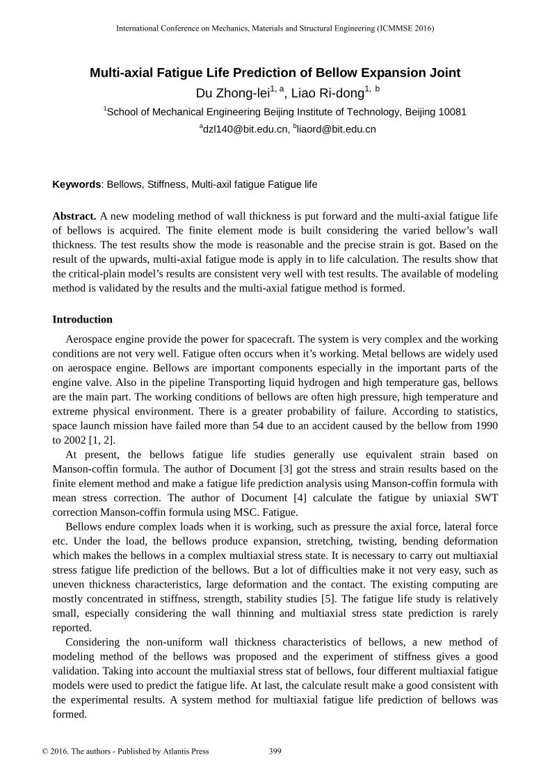
Multi-axial Fatigue Life Prediction of Bellow Expansion Joint Du Zhong-lei 1, a , Liao Ri-dong 1, b 1 School of Mechanical Engineering Beijing Institute of Technology, Beijing 10081 a [email protected], b [email protected] Keywords: Bellows, Stiffness, Multi-axil fatigue Fatigue life Abstract. A new modeling method of wall thickness is put forward and the multi-axial fatigue life of bellows is acquired. The finite element mode is built considering the varied bellow’s wall thickness. The test results show the mode is reasonable and the precise strain is got. Based on the result of the upwards, multi-axial fatigue mode is apply in to life calculation. The results show that the critical-plain model’s results are consistent very well with test results. The available of modeling method is validated by the results and the multi-axial fatigue method is formed. Introduction Aerospace engine provide the power for spacecraft. The system is very complex and the working conditions are not very well. Fatigue often occurs when it’s working. Metal bellows are widely used on aerospace engine. Bellows are important components especially in the important parts of the engine valve. Also in the pipeline Transporting liquid hydrogen and high temperature gas, bellows are the main part. The working conditions of bellows are often high pressure, high temperature and extreme physical environment. There is a greater probability of failure. According to statistics, space launch mission have failed more than 54 due to an accident caused by the bellow from 1990 to 2002 [1, 2]. At present, the bellows fatigue life studies generally use equivalent strain based on Manson-coffin formula. The author of Document [3] got the stress and strain results based on the finite element method and make a fatigue life prediction analysis using Manson-coffin formula with mean stress correction. The author of Document [4] calculate the fatigue by uniaxial SWT correction Manson-coffin formula using MSC. Fatigue. Bellows endure complex loads when it is working, such as pressure the axial force, lateral force etc. Under the load, the bellows produce expansion, stretching, twisting, bending deformation which makes the bellows in a complex multiaxial stress state. It is necessary to carry out multiaxial stress fatigue life prediction of the bellows. But a lot of difficulties make it not very easy, such as uneven thickness characteristics, large deformation and the contact. The existing computing are mostly concentrated in stiffness, strength, stability studies [5]. The fatigue life study is relatively small, especially considering the wall thinning and multiaxial stress state prediction is rarely reported. Considering the non-uniform wall thickness characteristics of bellows, a new method of modeling method of the bellows was proposed and the experiment of stiffness gives a good validation. Taking into account the multiaxial stress stat of bellows, four different multiaxial fatigue models were used to predict the fatigue life. At last, the calculate result make a good consistent with the experimental results. A system method for multiaxial fatigue life prediction of bellows was formed. International Conference on Mechanics, Materials and Structural Engineering (ICMMSE 2016) © 2016. The authors - Published by Atlantis Press 399
Transcript of Multi-axial Fatigue Life Prediction of Bellow Expansion Joint fileMulti-axial Fatigue Life...
Multi-axial Fatigue Life Prediction of Bellow Expansion Joint
Du Zhong-lei1, a, Liao Ri-dong1, b
1School of Mechanical Engineering Beijing Institute of Technology, Beijing [email protected], [email protected]
Keywords: Bellows, Stiffness, Multi-axil fatigue Fatigue life
Abstract. A new modeling method of wall thickness is put forward and the multi-axial fatigue life
of bellows is acquired. The finite element mode is built considering the varied bellow’s wall
thickness. The test results show the mode is reasonable and the precise strain is got. Based on the
result of the upwards, multi-axial fatigue mode is apply in to life calculation. The results show that
the critical-plain model’s results are consistent very well with test results. The available of modeling
method is validated by the results and the multi-axial fatigue method is formed.
Introduction
Aerospace engine provide the power for spacecraft. The system is very complex and the working
conditions are not very well. Fatigue often occurs when it’s working. Metal bellows are widely used
on aerospace engine. Bellows are important components especially in the important parts of the
engine valve. Also in the pipeline Transporting liquid hydrogen and high temperature gas, bellows
are the main part. The working conditions of bellows are often high pressure, high temperature and
extreme physical environment. There is a greater probability of failure. According to statistics,
space launch mission have failed more than 54 due to an accident caused by the bellow from 1990
to 2002 [1, 2].
At present, the bellows fatigue life studies generally use equivalent strain based on
Manson-coffin formula. The author of Document [3] got the stress and strain results based on the
finite element method and make a fatigue life prediction analysis using Manson-coffin formula with
mean stress correction. The author of Document [4] calculate the fatigue by uniaxial SWT
correction Manson-coffin formula using MSC. Fatigue.
Bellows endure complex loads when it is working, such as pressure the axial force, lateral force
etc. Under the load, the bellows produce expansion, stretching, twisting, bending deformation
which makes the bellows in a complex multiaxial stress state. It is necessary to carry out multiaxial
stress fatigue life prediction of the bellows. But a lot of difficulties make it not very easy, such as
uneven thickness characteristics, large deformation and the contact. The existing computing are
mostly concentrated in stiffness, strength, stability studies [5]. The fatigue life study is relatively
small, especially considering the wall thinning and multiaxial stress state prediction is rarely
reported.
Considering the non-uniform wall thickness characteristics of bellows, a new method of
modeling method of the bellows was proposed and the experiment of stiffness gives a good
validation. Taking into account the multiaxial stress stat of bellows, four different multiaxial fatigue
models were used to predict the fatigue life. At last, the calculate result make a good consistent with
the experimental results. A system method for multiaxial fatigue life prediction of bellows was
formed.
International Conference on Mechanics, Materials and Structural Engineering (ICMMSE 2016)
© 2016. The authors - Published by Atlantis Press 399
A New Modeling Method
The reasonable finite element model is foundation for accurate life prediction of bellows. Under
the hydraulic forming process of bellows, the actual size will result in a deviation to the design. The
thickness of the bellows will become not uniform. If we make a finite element analysis according to
the thickness of design model, great differences will exist in the experimental results and calculate
results. Based on the design size of the bellows, considering the impact of the actual process to its
thickness, a finite element model of the bellows was establish by exponentially thinning manner.
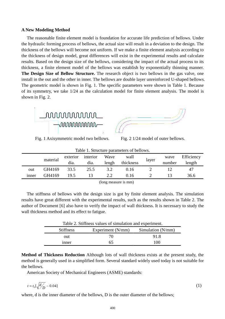
The Design Size of Bellow Structure. The research object is two bellows in the gas valve, one
install in the out and the other in inner. The bellows are double layer unreinforced U-shaped bellows.
The geometric model is shown in Fig. 1. The specific parameters were shown in Table 1. Because
of its symmetry, we take 1/24 as the calculation model for finite element analysis. The model is
shown in Fig. 2.
Fig. 1 Axisymmetric model two bellows. Fig. 2 1/24 model of outer bellows.
Table 1. Structure parameters of bellows.
materialexterior
dia.
interior
dia.
Wave
lengh
wall
thicknesslayer
wave
number
Efficiency
length
out GH4169 33.5 25.5 3.2 0.16 2 12 47
inner GH4169 19.5 13 2.2 0.16 2 13 36.6
(long measure is mm)
The stiffness of bellows with the design size is got by finite element analysis. The simulation
results have great different with the experimental results, such as the results shown in Table 2. The
author of Document [6] also have to verify the impact of wall thickness. It is necessary to study the
wall thickness method and its effect to fatigue.
Table 2. Stiffness values of simulation and experiment.
Stiffness Experiment (N/mm) Simulation (N/mm)
out 70 91.8
inner 65 100
Method of Thickness Reduction Although lots of wall thickness exists at the present study, the
method is generally used in a simplified form. Several standard widely used today is not suitable for
the bellows.
American Society of Mechanical Engineers (ASME) standards:
0[ 0.04]dt tD
= − (1)
where, d is the inner diameter of the bellows, D is the outer diameter of the bellows;
400
American Expansion Joint Manufacturers Association (EJMA) criteria:
00
p
dt t
d=
(2)
Japanese Industrial Standards JIS standard:
00 ( )
p
dt t
d=
(3)
where, d0 is the inner diameter of the bellows, d is the diameter of the measurement point;
The thickness calculated according to ASME formula is the average thickness. The actual
thickness should be gradually thinning trend from trough to peak. JIS and EJMA formula can
effectively simulate the actual production. A more general form is0( )x
p
dt
d= , where x is between 0
and 1 according to the actual process situation.
According to the theory above, a gradually thinning method were proposed. In order to ensure
the positional relationship of two bellows after thinning, the midline of two layers unchanged. By
setting the thinning rate to change the inside and outside layer thickness. The wall thickness is
associated with the radius.
Index thinning methods: The new method of thickness reduction is as follows:
0( )x
p
dt
d=
(4)
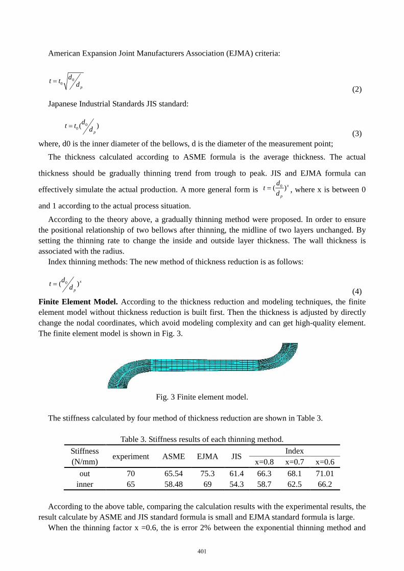
Finite Element Model. According to the thickness reduction and modeling techniques, the finite
element model without thickness reduction is built first. Then the thickness is adjusted by directly
change the nodal coordinates, which avoid modeling complexity and can get high-quality element.
The finite element model is shown in Fig. 3.
Fig. 3 Finite element model.
The stiffness calculated by four method of thickness reduction are shown in Table 3.
Table 3. Stiffness results of each thinning method.
Stiffness
(N/mm)experiment ASME EJMA JIS
Index
x=0.8 x=0.7 x=0.6
out 70 65.54 75.3 61.4 66.3 68.1 71.01
inner 65 58.48 69 54.3 58.7 62.5 66.2
According to the above table, comparing the calculation results with the experimental results, the
result calculate by ASME and JIS standard formula is small and EJMA standard formula is large.
When the thinning factor x =0.6, the is error 2% between the exponential thinning method and
401
experimental values with a higher degree of agreement. The results showed that the index thinning
method can well simulate the bellows thinning phenomenon caused by the process. The analysis
results meet the required accuracy very well. In the subsequent fatigue life calculation, all models
adopt the index thinning method.
Fatigue Life Prediction and Analysis
The finite element models were got by the exponential thinning method. The stress/strain of the
dangerous point was get under the actual load conditions. Fatigue life can be obtained by combine
the material fatigue characteristics, multiaxial fatigue prediction models. The load conditions and
material parameters, the multiaxial fatigue life prediction model and analysis are as follows.
Load Condition and Material Characteristic. The Bellows assembly structure is used for two
different gas valve. The status of their work in different situations can be grouped into eight
different conditions. The exact parameters of stretching, compression displacement and pressure
was shown in Table 4. The out bellows only under interior pressure and the inner bellows only
under external pressure.
Table 4. Load condition of bellows.
Outer tube Inner tube
displacement pressure displacement pressure
stretch compression stretch compression stretch compression stretching stretch
1 3.5 3.5 0 7 3.5 3.5 7.2 7.2
2 1 3.8 0 7 1 3.8 7.2 7.2
3 3.5 3.5 0 7 3.5 3.5 6.5 5
4 1 3.8 0 7 1 3.8 5 6.5
5 3.5 3.5 0 6.5 3.5 3.5 2.75 2.75
6 1 3.8 0 6.5 1 3.8 2.75 2.75
7 3.5 3.5 0 6.5 3.5 3.5 2.75 0.1
8 1 3.8 0 6.5 1 3.8 0.1 2.75
(The displacement unit is mm, pressure is measured in MPa)
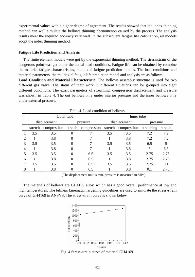
The materials of bellows are GH4169 alloy, which has a good overall performance at low and
high temperatures. The bilinear kinematic hardening guidelines are used to simulate the stress-strain
curve of GH4169 in ANSYS. The stress-strain curve is shown below.
Fig. 4 Stress-strain curve of material GH4169.
402
Damage Parameters and Life Predict Equation How to choose the stress / strain component
participate in fatigue analysis? What is the relationship between the fatigue life and stress / strain
component? These issues need to be resolved by multiaxial fatigue model. Four models are
described in detail, such as maximum principal strain, maximum shear strain model, critical plane
model, critical plane correction models.
The maximum principal strain model. The maximum principal strain method is equivalent
strain method of life prediction. This method considers the maximum principal strain is the main
parameter to measure the material damage and fatigue life.
( ) ( )1 max 2 22
b cf
f f fN NE
σεε
′∆′= +
(5)
where, 1 maxε∆ is the maximum principal strain range at the danger point, fσ ′ is the fatigue
strength coefficient, fε ′ is the fatigue ductility coefficient, b is the fatigue strength index, c is the
fatigue ductility exponent, Nf is the fatigue life, E is the elastic modulus.
The maximum shear strain model [7]. The maximum shear strain model considered the
maximum shear strain is the main damage parameter, which determines the fatigue life.
( )( ) ( ) ( )max
12 1 2
2
b ce f
f p f fN NE
ν σγν ε
′+∆′= + +
(6)
where, max 1 3( )γ ε ε∆ = ∆ − , The elastic modulus ve take the value 0.3, vp value is 0.5, the lifeprediction formula as follows
( ) ( )max 1.3 2 1.5 22
b cf
f f fN NE
σγε
′∆′= +
(7)
Critical plane model. Early crack is formed along the direction of the plane of maximum shear
strain, and then expand approximately along the direction of perpendicularity the plane. Usually
critical plane is defined maximum shear strain plane. The damage parameters are mix with
maximum shear strain and maximum normal strain of the critical plane. We obtain the following
formula for life prediction
( ) ( )2 2max
12 2
3
b cf
n f f fN NE
σε γ ε
′′∆ + ∆ = +
(8)
In the above formula, 1 3( )
2n
ε εε
∆ +∆ = is the normal strain range at the vertical direction of
maximum shear plane, max 1 3( )γ ε ε∆ = ∆ − is the maximum shear strain range.
Critical plane correction model. The author of document [8] proposed a new damage
parameter on the basis of critical plane model:
2 2 1/2max( / 3)cr
eq nkε ε γ= +(9)
Combine the Manson-Coffin equation, the life prediction model as follows:
403
12 2 2n max / 3) (1.3 0.7 ) (2 ) (1.5 0.5 ) (2 )
f b cf f fk N k N
E
σε γ ε
′′∆ + ∆ = + + +
(10)
where, k is the influence factor of normal strain, 0 <k <1 [9].
Fatigue Life Calculation and Results Analysis. The stress/strain of the dangerous point is the
basis of fatigue life prediction. The state of stress and strain at the peaks and valleys is a
three-dimensional state. The equivalent rule is often used in the study of the fatigue properties.
Because of the stress and strain components is tensor, a single component can not characterize the
complex three-dimensional stress-strain state. According to the literature [10], this paper use Von
Mises stress to judge by the dangerous points.
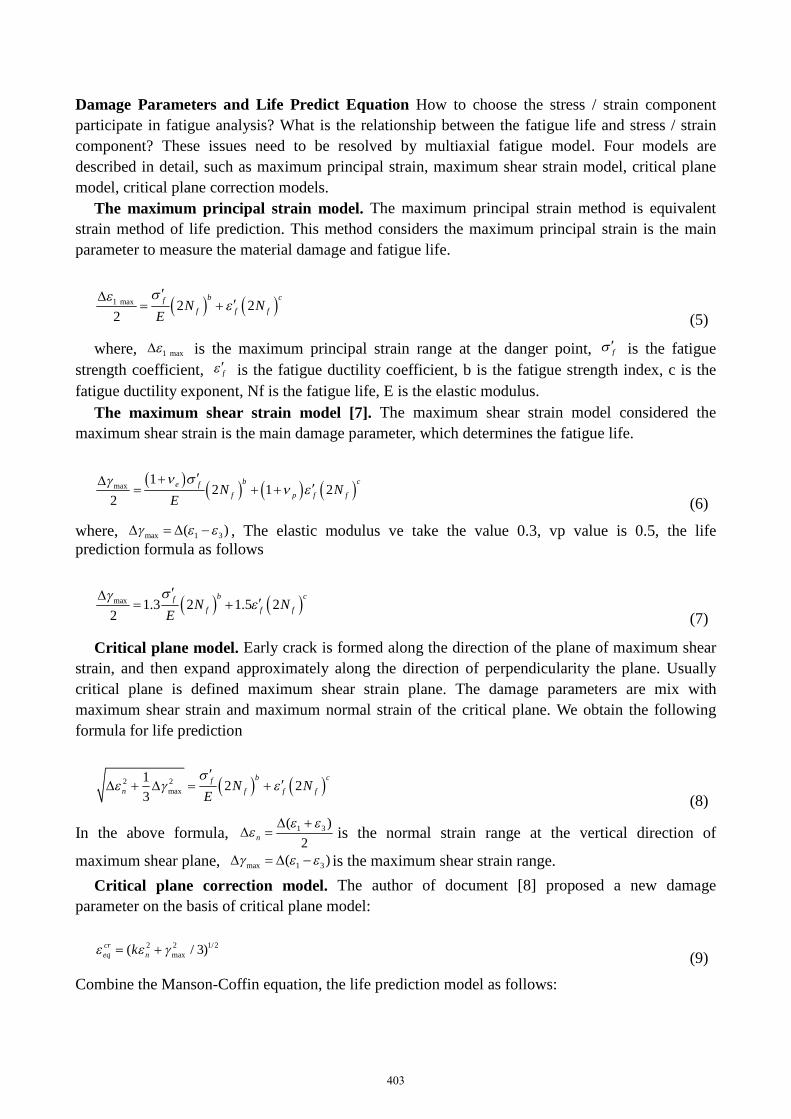
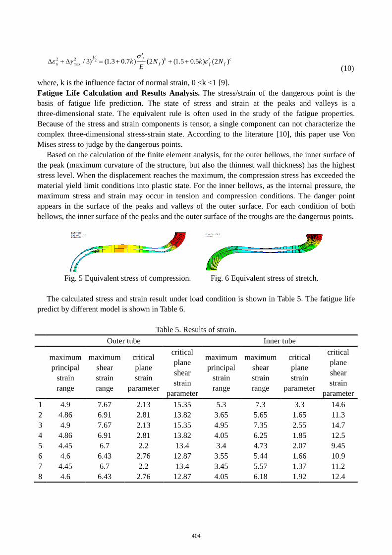
Based on the calculation of the finite element analysis, for the outer bellows, the inner surface of
the peak (maximum curvature of the structure, but also the thinnest wall thickness) has the highest
stress level. When the displacement reaches the maximum, the compression stress has exceeded the
material yield limit conditions into plastic state. For the inner bellows, as the internal pressure, the
maximum stress and strain may occur in tension and compression conditions. The danger point
appears in the surface of the peaks and valleys of the outer surface. For each condition of both
bellows, the inner surface of the peaks and the outer surface of the troughs are the dangerous points.
Fig. 5 Equivalent stress of compression. Fig. 6 Equivalent stress of stretch.
The calculated stress and strain result under load condition is shown in Table 5. The fatigue life
predict by different model is shown in Table 6.
Table 5. Results of strain.
Outer tube Inner tube
maximum
principal
strain
range
maximum
shear
strain
range
critical
plane
strain
parameter
critical
plane
shear
strain
parameter
maximum
principal
strain
range
maximum
shear
strain
range
critical
plane
strain
parameter
critical
plane
shear
strain
parameter
1 4.9 7.67 2.13 15.35 5.3 7.3 3.3 14.6
2 4.86 6.91 2.81 13.82 3.65 5.65 1.65 11.3
3 4.9 7.67 2.13 15.35 4.95 7.35 2.55 14.7
4 4.86 6.91 2.81 13.82 4.05 6.25 1.85 12.5
5 4.45 6.7 2.2 13.4 3.4 4.73 2.07 9.45
6 4.6 6.43 2.76 12.87 3.55 5.44 1.66 10.9
7 4.45 6.7 2.2 13.4 3.45 5.57 1.37 11.2
8 4.6 6.43 2.76 12.87 4.05 6.18 1.92 12.4
404
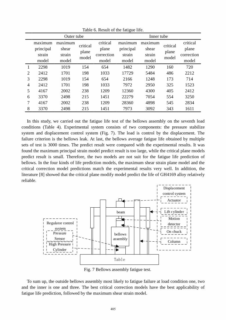
Table 6. Result of the fatigue life.
Outer tube Inner tube
maximum
principal
strain
model
maximum
shear
strain
model
critical
plane
model
critical
plane
correction
model
maximum
principal
strain
model
maximum
shear
strain
model
critical
plane
model
critical
plane
correction
model
1 2298 1019 154 654 1482 1290 160 720
2 2412 1701 198 1033 17729 5484 486 2212
3 2298 1019 154 654 2166 1248 173 714
4 2412 1701 198 1033 7972 2950 325 1523
5 4167 2002 238 1209 12360 4300 405 2412
6 3370 2498 215 1451 22279 7054 554 3250
7 4167 2002 238 1209 28360 4898 545 2834
8 3370 2498 215 1451 7973 3092 343 1611
In this study, we carried out the fatigue life test of the bellows assembly on the seventh load
conditions (Table 4). Experimental system consists of two components: the pressure stabilize
system and displacement control system (Fig. 7). The load is control by the displacement. The
failure criterion is the bellows leak. At last, the bellows average fatigue life obtained by multiple
sets of test is 3000 times. The predict result were compared with the experimental results. It was
found the maximum principal strain model predict result is too large, while the critical plane models
predict result is small. Therefore, the two models are not suit for the fatigue life prediction of
bellows. In the four kinds of life prediction models, the maximum shear strain plane model and the
critical correction model predictions match the experimental results very well. In addition, the
literature [8] showed that the critical plane modify model predict the life of GH4169 alloy relatively
reliable.
Table
beam
bellowsassembly
Regulator control
system
Actuator
Pressure
Sensor
Motion
detector
On chuck
Lift cylinder
High Pressure
Cylinder
Column
Displacement
control system
Fig. 7 Bellows assembly fatigue test.
To sum up, the outside bellows assembly most likely to fatigue failure at load condition one, two
and the inner is one and three. The best critical correction models have the best applicability of
fatigue life prediction, followed by the maximum shear strain model.
405
Conclusion
Considering the non-uniform wall thickness of the bellows, precision finite element model was
built. The multiaxial fatigue life of bellows is calculate by the maximum principal strain model,
maximum shear strain model, the critical plane model, critical plane correction model. The main
conclusions are: (1) A new modeling method was proposed. This modeling method combines the
features of an international standard formulas ASME, JIS, EJMA. The prediction stiffness was
compared with the experimental value. (2) The bellows dangerous point determined by the Von
Mises stress is the inner surface of the peaks and the outer surface of troughs. (3) A system
multiaxial fatigue life prediction method of bellows is formed. The outer bellows fatigue failure is
most likely to occur at load condition one, two and one, three for inner bellows. The critical plane
correction models have the best applicability in bellows multiaxial fatigue life prediction.
References
[1] G. J. Xie, Resesrch of real-time fault detection technology and system for liquid rocket engineturbopump, Nat. Univ. Defense Technol. 2006.
[2] Z. P. Zhang, Fundamental study of fault monitoring and diagnostic technology of liquid rocketengine, J. Propul. Tech. 23(5) (2002) 353-359.
[3] C. B. Yu, J. J. Wang, C. L. Li et al. Finite element analysis to multilayer U-shaped bellows’fatigue life, Press. Vessel Technol. 25(2) (2008) 23-27.
[4] N. N. Huang, L. H. Song, G. J. Wei et al. Fatigue life of finite element analysis metal bellowsfor valves, Valve. 5 (2008) 30-34.
[5] S. Wang, J. J. Wang, C. L. Li, et al. Nonlinear finite element analysis of multilayer bellows’axial stiffness considering the influence of inter-layer friction. Press. Vessel Technol. 24(12) (2007)12-15.
[6] Z. J. Tan, L. Y. Cao, R. D. Liao, et al. Finite element analysis to the multilayer U-shapedbellows’ axial stiffness and critical load. J. Mech. Strength, 26(1) (2004) 49-53.
[7] D. G. Shang, W. X. Yao. Study on multiaxial fatigue damage parameters based on the criticalplane approach. Acta Aeronaut. Astronaut. Sinica. 20(4) (2004) 295-298.
[8] J. G. Wang, H. Y. Wang, D. G. Shang, Fatigue life prediction for GH4169 superalloy undermulti-axial cyclic loading at 650°C. J. Mech. Strength, 30(2) (2008) 324-328.
[9] N. Cai. High temperature fatigue properties and Life Prediction under multiaxial loading.BeiJing: Beijing University of Technology, 2004, 66-69.
[10]A. Savaidis, G. Savaidis, Ch. Zhang. Elastic-plastic FE analysis of a notched cylinder undermultiaxial nonproportional fatigue loading with variable amplitudes. Comput. Struct. 80(25) (2002)1907-1918.
406