MU120002A STM-1/OC-3 Unit Operation Manual · Provides an overview of the MP1220A and describes its...
64
Document No.: M-W1309AE-6.0 ANRITSU CORPORATION MU120002A STM-1/OC-3 Unit Operation Manual Read this manual before using the equipment. Keep this manual with the equipment. Sixth Edition
Transcript of MU120002A STM-1/OC-3 Unit Operation Manual · Provides an overview of the MP1220A and describes its...
Document No.: M-W1309AE-6.0
ANRITSU CORPORATION
MU120002ASTM-1/OC-3 UnitOperation Manual
Read this manual before using the equipment.Keep this manual with the equipment.
Sixth Edition
ii
Safety SymbolsTo prevent the risk of personal injury or loss related to equipment malfunction, Anritsu Corporation uses the followingsafety symbols to indicate safety-related information. Insure that you clearly understand the meanings of the sym-bols BEFORE using the equipment. Some or all of the following five symbols may not be used on all Anritsuequipment. In addition, there may be other labels attached to products which are not shown in the diagrams in thismanual.
Symbols used in manualThis indicates a very dangerous procedure that could result in serious injury ordeath if not performed properly.
This indicates a hazardous procedure that could result in serious injury or death ifnot performed properly.
This indicates a hazardous procedure or danger that could result in light-to-severeinjury, or loss related to equipment malfunction, if proper precautions are not taken.
Safety Symbols Used on Equipment and in ManualThe following safety symbols are used inside or on the equipment near operation locations to provide informationabout safety items and operation precautions. Insure that you clearly understand the meanings of the symbolsand take the necessary precautions BEFORE using the equipment.
This indicates a prohibited operation. The prohibited operation is indicated sym-bolically in or near the barred circle.
This indicates an obligatory safety precaution. The obligatory operation is indicat-ed symbolically in or near the circle.
This indicates warning or caution. The contents are indicated symbolically in ornear the triangle.
This indicates a note. The contents are described in the box.
These indicate that the marked part should be recycled.
MU120002ASTM-1/OC-3 UnitOperation Manual
19 February 1998 (First Edition)21 September 2004 (Sixth Edition)
Copyright © 1998-2004, ANRITSU CORPORATION.All rights reserved. No part of this manual may be reproduced without the prior written permission of thepublisher.The contents of this manual may be changed without prior notice.Printed in Japan
DANGER
WARNING
CAUTION

For Safety
iii
WARNING 1. ALWAYS refer to the operation manual when working near locations
at which the alert mark shown on the left is attached. If the opera-tion, etc., is performed without heeding the advice in the operationmanual, there is a risk of personal injury. In addition, the equipmentperformance may be reduced.Moreover, this alert mark is sometimes used with other marks anddescriptions indicating other dangers.
2. Laser radiation warning• NEVER look directly into the cable connector on the equipment
nor into the end of a cable connected to the equipment. If laserradiation enters the eye, there is a risk of injury.
• The Laser Safety label is attached to the equipment for safety useas indicated in "Laser Safety" on a following page.
3. This equipment cannot be repaired by the user. DO NOT attempt toopen the cabinet or to disassemble internal parts. Only Anritsu-trained service personnel or staff from your sales representative witha knowledge of electrical fire and shock hazards should service thisequipment. There are high-voltage parts in this equipment present-ing a risk of severe injury or fatal electric shock to untrained person-nel. In addition, there is a risk of damage to precision parts.
Repair

For Safety
iv
CAUTION 1. Never input a signal of more than the indicated value between the
measured terminal and ground. Input of an excessive signal maydamage the equipment.
Check Terminal
For Safety
v
The laser in this equipment is classified as Class 1 according to the IEC60825-1 specifications, or as Class I according to the 21CFR 1040.10specifications. These classes of lasers are safe under reasonably fore-seeable operating conditions.
Classes are indicated on the label attached near the laser-radiations.
Class 1 indicate the danger degree of the laser radiation specified belowaccording to IEC 60825-1.
Class 1: Lasers that are safe under reasonably foreseeable conditionsof operation, including the use of optical instruments for intra-beam viewing.
Laser Safety

vi
Equipment CertificateAnritsu Corporation certifies that this equipment was tested beforeshipment using calibrated measuring instruments with direct traceabilityto public testing organizations recognized by national research laborato-ries including the National Institute of Advanced Industrial Science andTechnology, and the National Institute of Information and Communica-tions Technology, and was found to meet the published specifications.
Anritsu WarrantyAnritsu Corporation will repair this equipment free-of-charge if a mal-function occurs within 1 year after shipment due to a manufacturing fault,provided that this warranty is rendered void under any or all of the fol-lowing conditions.
• The fault is outside the scope of the warranty conditions described inthe operation manual.
• The fault is due to mishandling, misuse, or unauthorized modificationor repair of the equipment by the customer.
• The fault is due to severe usage clearly exceeding normal usage.• The fault is due to improper or insufficient maintenance by the cus-
tomer.• The fault is due to natural disaster including fire, flooding, earthquake,
etc.• The fault is due to use of non-specified peripheral equipment,
peripheral parts, consumables, etc.• The fault is due to use of a non-specified power supply or in a non-
specified installation location.
In addition, this warranty is valid only for the original equipment pur-chaser. It is not transferable if the equipment is resold.
Anritsu Corporation will not accept liability for equipment faults due tounforeseen and unusual circumstances, nor for faults due to mishandlingby the customer.
Anritsu Corporation ContactIf this equipment develops a fault, contact Anritsu Service and Sales of-fices at the address at the end of paper-edition manual or the separate fileof CD-edition manual.

vii
CE Conformity markingAnritsu affixes the CE Conformity marking on the following product (s) inaccordance with the Council Directive 93/68/EEC to indicate that theyconform to the EMC and LVD directive of the European Union (EU).
CE marking
1. Product ModelPlug-in Units: MU120002A STM-1/OC-3 Unit
2. Applied Directive and StandardsWhen the MU120002A STM-1/OC-3 Unit is installed in the MP1220A,the applied directive and standards of this Unit are conformed to thoseof the MP1220A main frame.
PS: About main frameThe kind of main frame (a measuring apparatus) will be to increase.Please, contact us about the newest information of the main frame.
viii
C-tick Conformity markingAnritsu affixes the C-tick marking on the following product (s) in accor-dance with the regulation to indicate that they conform to the EMCframework of Australia/New Zealand.
C-tick marking
1. Product ModelPlug-in Units: MU120002A STM-1/OC-3 Unit
2. Applied Directive and StandardsWhen the MU120002A STM-1/OC-3 Unit is installed in the MP1220A,the applied directive and standards of this Unit are conformed to thoseof the MP1220A main frame.
PS: About main frameThe kind of main frame (a measuring apparatus) will be to increase.Please, contact us about the newest information of the main frame.
I
Preface
Organization of the Operation Manual
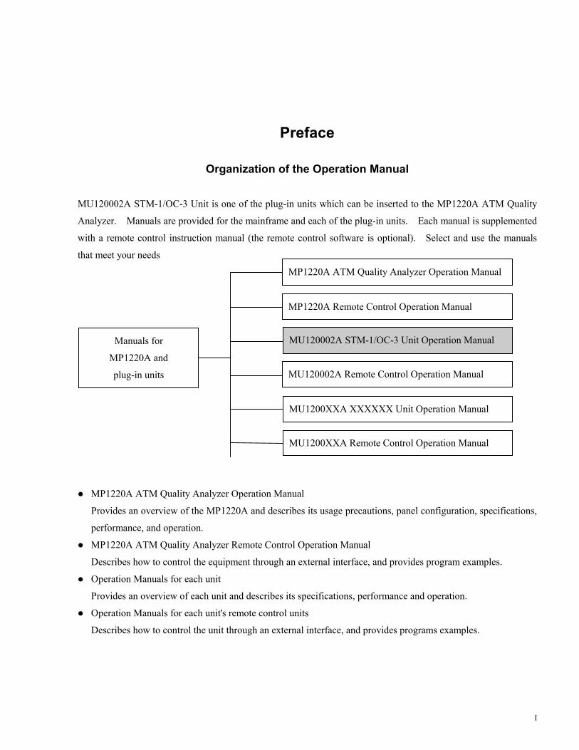
MU120002A STM-1/OC-3 Unit is one of the plug-in units which can be inserted to the MP1220A ATM Quality
Analyzer. Manuals are provided for the mainframe and each of the plug-in units. Each manual is supplemented
with a remote control instruction manual (the remote control software is optional). Select and use the manuals
that meet your needs
� MP1220A ATM Quality Analyzer Operation Manual
Provides an overview of the MP1220A and describes its usage precautions, panel configuration, specifications,
performance, and operation.
� MP1220A ATM Quality Analyzer Remote Control Operation Manual
Describes how to control the equipment through an external interface, and provides program examples.
� Operation Manuals for each unit
Provides an overview of each unit and describes its specifications, performance and operation.
� Operation Manuals for each unit's remote control units
Describes how to control the unit through an external interface, and provides programs examples.
MP1220A ATM Quality Analyzer Operation Manual
Manuals for
MP1220A and
plug-in units
MP1220A Remote Control Operation Manual
MU120002A STM-1/OC-3 Unit Operation Manual
MU120002A Remote Control Operation Manual
MU1200XXA XXXXXX Unit Operation Manual
MU1200XXA Remote Control Operation Manual
II
Contents
For Safety ・・・・・・・・・・・・・・・・・・・・・・・・・・・・・・・・・・・・・・・・・・・・・・・・・・・・・・・・・・・・・・・・・・・・・・・・・・・・・・・ iii
Preface ・・・・・・・・・・・・・・・・・・・・・・・・・・・・・・・・・・・・・・・・・・・・・・・・・・・・・・・・・・・・・・・・・・・・・・・・・・・・・・・・I
Section 1 Overview ・・・・・・・・・・・・・・・・・・・・・・・・・・・・・・・・・・・・・・・・・・・・・・・・・・・・・・・・・・・・・・・・・・・・・ 1-11.1 Overview of the Product・・・・・・・・・・・・・・・・・・・・・・・・・・・・・・・・・・・・・・・・・・・・・・・・・・・・・・・・・・・・・・・・ 1-1
1.2 Specifications ・・・・・・・・・・・・・・・・・・・・・・・・・・・・・・・・・・・・・・・・・・・・・・・・・・・・・・・・・・・・・・・・・・・・・・・・ 1-2
1.3 Configuration ・・・・・・・・・・・・・・・・・・・・・・・・・・・・・・・・・・・・・・・・・・・・・・・・・・・・・・・・・・・・・・・・・・・・・・・・ 1-6
1.3.1 Standard Configuration ・・・・・・・・・・・・・・・・・・・・・・・・・・・・・・・・・・・・・・・・・・・・・・・・・・・・・・・・・・・・・ 1-6
1.3.2 Application Parts・・・・・・・・・・・・・・・・・・・・・・・・・・・・・・・・・・・・・・・・・・・・・・・・・・・・・・・・・・・・・・・・・・ 1-6
Section 2 Preparation For Use ・・・・・・・・・・・・・・・・・・・・・・・・・・・・・・・・・・・・・・・・・・・・・・・・・・・・・・・・・・・ 2-12.1 Environmental Requirements ・・・・・・・・・・・・・・・・・・・・・・・・・・・・・・・・・・・・・・・・・・・・・・・・・・・・・・・・・・・・ 2-1
2.2 Safety Precautions ・・・・・・・・・・・・・・・・・・・・・・・・・・・・・・・・・・・・・・・・・・・・・・・・・・・・・・・・・・・・・・・・・・・・ 2-2
2.3 Warming Up・・・・・・・・・・・・・・・・・・・・・・・・・・・・・・・・・・・・・・・・・・・・・・・・・・・・・・・・・・・・・・・・・・・・・・・・・ 2-3
Section 3 Description Of The Panels ・・・・・・・・・・・・・・・・・・・・・・・・・・・・・・・・・・・・・・・・・・・・・・・・・・・・・・ 3-13.1 Organization of Panels and Their Descriptions ・・・・・・・・・・・・・・・・・・・・・・・・・・・・・・・・・・・・・・・・・・・・・・ 3-1
Section 4 Description Of The Screen ・・・・・・・・・・・・・・・・・・・・・・・・・・・・・・・・・・・・・・・・・・・・・・・・・・・・・・ 4-14.1 MU120002A STM-1/OC-3 UNIT Window・・・・・・・・・・・・・・・・・・・・・・・・・・・・・・・・・・・・・・・・・・・・・・・・・ 4-1
4.2 Construction Panel ・・・・・・・・・・・・・・・・・・・・・・・・・・・・・・・・・・・・・・・・・・・・・・・・・・・・・・・・・・・・・・・・・・・・ 4-2
4.2.1 Physical Interface Setup Dialog Box・・・・・・・・・・・・・・・・・・・・・・・・・・・・・・・・・・・・・・・・・・・・・・・・・・・ 4-4
4.2.2 Search Condition Setup Dialog Box ・・・・・・・・・・・・・・・・・・・・・・・・・・・・・・・・・・・・・・・・・・・・・・・・・・・ 4-5
4.3 Tx-Setup Panel ・・・・・・・・・・・・・・・・・・・・・・・・・・・・・・・・・・・・・・・・・・・・・・・・・・・・・・・・・・・・・・・・・・・・・・・ 4-6
4.3.1 Tc Setup Dialog Box・・・・・・・・・・・・・・・・・・・・・・・・・・・・・・・・・・・・・・・・・・・・・・・・・・・・・・・・・・・・・・・ 4-7
4.3.1.1 Byte Setup dialog box ・・・・・・・・・・・・・・・・・・・・・・・・・・・・・・・・・・・・・・・・・・・・・・・・・・・・・・・・・・ 4-9
4.3.2 Alarm/Error/Pointer Setup Dialog Box・・・・・・・・・・・・・・・・・・・・・・・・・・・・・・・・・・・・・・・・・・・・・・・・ 4-10
4.3.3 Overhead Editor ・・・・・・・・・・・・・・・・・・・・・・・・・・・・・・・・・・・・・・・・・・・・・・・・・・・・・・・・・・・・・・・・・ 4-13
4.3.4 Path Trace Editor (J0, J1) ・・・・・・・・・・・・・・・・・・・・・・・・・・・・・・・・・・・・・・・・・・・・・・・・・・・・・・・・・・ 4-15
4.4 Rx-Setup Panel・・・・・・・・・・・・・・・・・・・・・・・・・・・・・・・・・・・・・・・・・・・・・・・・・・・・・・・・・・・・・・・・・・・・・・ 4-17
4.4.1 TC Setup Dialog Box ・・・・・・・・・・・・・・・・・・・・・・・・・・・・・・・・・・・・・・・・・・・・・・・・・・・・・・・・・・・・・ 4-18
4.4.2 Trigger Setup Dialog Box ・・・・・・・・・・・・・・・・・・・・・・・・・・・・・・・・・・・・・・・・・・・・・・・・・・・・・・・・・・ 4-19
III
4.5 Alarm/Event Panel ・・・・・・・・・・・・・・・・・・・・・・・・・・・・・・・・・・・・・・・・・・・・・・・・・・・・・・・・・・・・・・・・・・・ 4-20
4.5.1 Layout Dialog Box ・・・・・・・・・・・・・・・・・・・・・・・・・・・・・・・・・・・・・・・・・・・・・・・・・・・・・・・・・・・・・・・ 4-21
4.6 Analyze Panel・・・・・・・・・・・・・・・・・・・・・・・・・・・・・・・・・・・・・・・・・・・・・・・・・・・・・・・・・・・・・・・・・・・・・・・ 4-22
4.6.1 Jump Dialog Box・・・・・・・・・・・・・・・・・・・・・・・・・・・・・・・・・・・・・・・・・・・・・・・・・・・・・・・・・・・・・・・・・ 4-23
4.6.2 Analyze Setup Dialog Box ・・・・・・・・・・・・・・・・・・・・・・・・・・・・・・・・・・・・・・・・・・・・・・・・・・・・・・・・・ 4-24
4.7 Monitor Panel・・・・・・・・・・・・・・・・・・・・・・・・・・・・・・・・・・・・・・・・・・・・・・・・・・・・・・・・・・・・・・・・・・・・・・・ 4-25
4.8 Pointer History Panel ・・・・・・・・・・・・・・・・・・・・・・・・・・・・・・・・・・・・・・・・・・・・・・・・・・・・・・・・・・・・・・・・・ 4-26
4.8.1 Jump Dialog Box・・・・・・・・・・・・・・・・・・・・・・・・・・・・・・・・・・・・・・・・・・・・・・・・・・・・・・・・・・・・・・・・・ 4-27
Section 5 Measurement ・・・・・・・・・・・・・・・・・・・・・・・・・・・・・・・・・・・・・・・・・・・・・・・・・・・・・・・・・・・・・・・・・ 5-15.1 Performance Measurement・・・・・・・・・・・・・・・・・・・・・・・・・・・・・・・・・・・・・・・・・・・・・・・・・・・・・・・・・・・・・・ 5-1
Section 6 Performance Test ・・・・・・・・・・・・・・・・・・・・・・・・・・・・・・・・・・・・・・・・・・・・・・・・・・・・・・・・・・・・・ 6-16.1 About Performance Tests ・・・・・・・・・・・・・・・・・・・・・・・・・・・・・・・・・・・・・・・・・・・・・・・・・・・・・・・・・・・・・・ 6-1
6.1.1 Alarm/Error Measurement Test・・・・・・・・・・・・・・・・・・・・・・・・・・・・・・・・・・・・・・・・・・・・・・・・・・・・・・・ 6-2
Section 7 Maintenance ・・・・・・・・・・・・・・・・・・・・・・・・・・・・・・・・・・・・・・・・・・・・・・・・・・・・・・・・・・・・・・・・・・ 7-17.1 Daily Maintenance ・・・・・・・・・・・・・・・・・・・・・・・・・・・・・・・・・・・・・・・・・・・・・・・・・・・・・・・・・・・・・・・・・・・・ 7-1
7.2 Notes on Storage ・・・・・・・・・・・・・・・・・・・・・・・・・・・・・・・・・・・・・・・・・・・・・・・・・・・・・・・・・・・・・・・・・・・・・ 7-2
7.3 Transportation・・・・・・・・・・・・・・・・・・・・・・・・・・・・・・・・・・・・・・・・・・・・・・・・・・・・・・・・・・・・・・・・・・・・・・・・ 7-3
7.4 Calibration ・・・・・・・・・・・・・・・・・・・・・・・・・・・・・・・・・・・・・・・・・・・・・・・・・・・・・・・・・・・・・・・・・・・・・・・・・・ 7-4
Appendix ・・・・・・・・・・・・・・・・・・・・・・・・・・・・・・・・・・・・・・・・・・・・・・・・・・・・・・・・・・・・・・・・・・・・・・・・・・・・・・・ A-1
Index ・・・・・・・・・・・・・・・・・・・・・・・・・・・・・・・・・・・・・・・・・・・・・・・・・・・・・・・・・・・・・・・・・・・・・・・・・・・・・・・・・・・・ I-1

IV.
Section 1 Overview
1-1
Section 1 Overview
1.1 Overview of the Product
MU120002A STM-1/OC-3 UNIT (this unit), which is to be inserted to a slot in the MP1220A ATM quality
analyzer (main frame), adds the frame to or terminates the 156Mb/s signal, and gains HEC synchronization to the
signal.
The optical and electrical input/output interfaces are provided in this unit.
Features
● Loopback function
・Reception loopback (the received signal, as well as being measured by this unit, is redirected inside the unit
to the transmitter side, and is sent to the external terminal, MU120020A QoS unit, and MU120021A
protocol unit.)
・Transmission loopback (the transmission signal, as well as sent to the external, is redirected and
measured in the unit.)
● Error/Alarm measurement
Various types of error/alarms including error ratios, error count, error status display, and warning status
display.
● Cell number count by HEC function
・Number of cells disposed due to header error.
・Number of cells whose header are error corrected.

Section 1 Overview
1-2
1.2 Specifications
Table 1-1 shows the specifications of this unit.
Table 1-1 Specifications
Number Item Specification11.1
Input/outputOutput
Transmission bitrateOutput levelModeEmission center
wave lengthCodeQuenching ratioConnectorOutput waveform
Enable to select Optical or CMI.Optical output155.520Mb/s±10ppm (internal clock)-15 to -8dBmSingle1.31μm band
NRZ8.2dB or moreSC (Duplex structure with Reception)Satisfies G.957 (ITU-T) and TA-NWT-000253.
1.2 InputReception bit rateInput levelOptical reception
wave length bandCodeConnector
Optical input155.520Mb/s±100ppm-29 to -8dBm1.31μm band
NRZDuplex structure with Transmission
1.3 CMI OutputTransmission bitrateOutput waveformCodeConnector
Electrical output155.520Mb/s±10ppm (internal clock)Conforms to ITU-T G.703 pulse mask.CMIBNC75Ω
1.4 CMI IntputReception bit rateInput level
CodeConnector
Electrical intput155.520Mb/s±100ppm1Vp-p±0.1V + cable loss 0 to 12dB
When monitoring : 0.1Vp-p ± 0.01VCMIBNC75Ω
1.5 Ext Clk InputFrequencylevelconnector
155.520MHz±100ppm (rectangular wave only)0.6 to 1.2Vp-pBNC 50Ω
Section 1 Overview
1-3
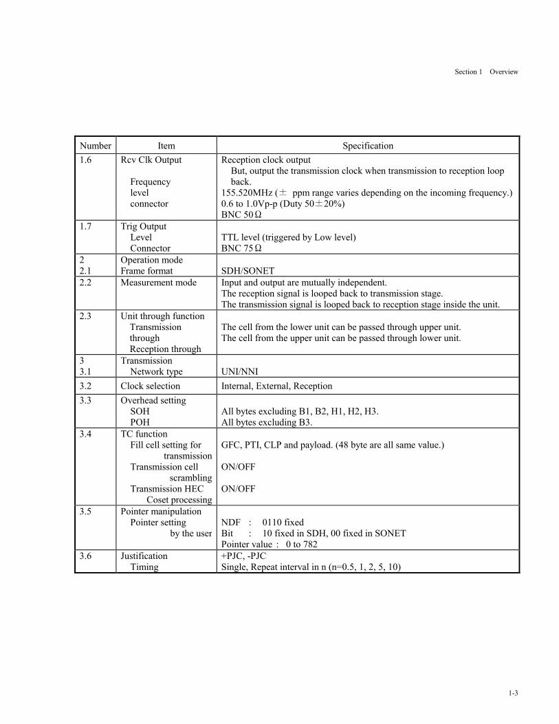
Number Item Specification1.6 Rcv Clk Output
Frequencylevelconnector
Reception clock outputBut, output the transmission clock when transmission to reception loopback.
155.520MHz (± ppm range varies depending on the incoming frequency.)0.6 to 1.0Vp-p (Duty 50±20%)BNC 50Ω
1.7 Trig OutputLevelConnector
TTL level (triggered by Low level)BNC 75Ω
22.1
Operation modeFrame format SDH/SONET
2.2 Measurement mode Input and output are mutually independent.The reception signal is looped back to transmission stage.The transmission signal is looped back to reception stage inside the unit.
2.3 Unit through functionTransmissionthroughReception through
The cell from the lower unit can be passed through upper unit.The cell from the upper unit can be passed through lower unit.
33.1
TransmissionNetwork type UNI/NNI
3.2 Clock selection Internal, External, Reception3.3 Overhead setting
SOHPOH
All bytes excluding B1, B2, H1, H2, H3.All bytes excluding B3.
3.4 TC functionFill cell setting for
transmissionTransmission cell
scramblingTransmission HEC
Coset processing
GFC, PTI, CLP and payload. (48 byte are all same value.)
ON/OFF
ON/OFF
3.5 Pointer manipulationPointer setting
by the userNDF : 0110 fixedBit : 10 fixed in SDH, 00 fixed in SONETPointer value : 0 to 782
3.6 JustificationTiming
+PJC, -PJCSingle, Repeat interval in n (n=0.5, 1, 2, 5, 10)
Section 1 Overview
1-4
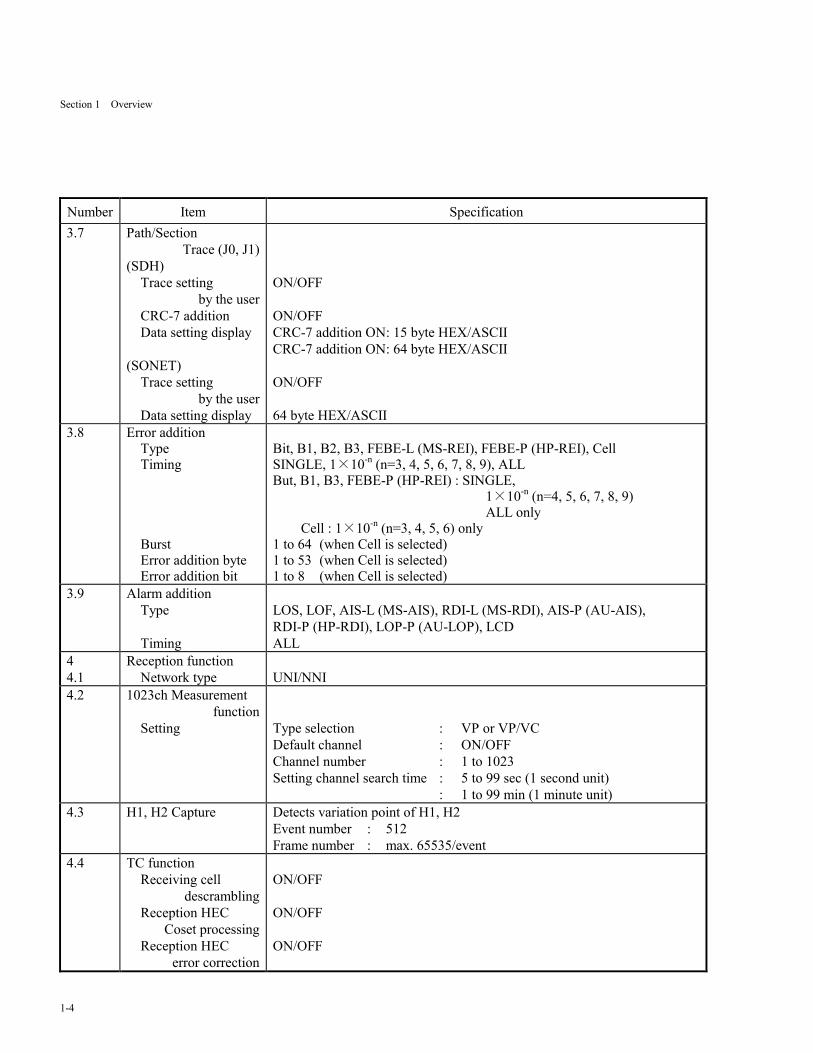
Number Item Specification3.7 Path/Section
Trace (J0, J1)(SDH)
Trace settingby the user
CRC-7 additionData setting display
(SONET)Trace setting
by the userData setting display
ON/OFF
ON/OFFCRC-7 addition ON: 15 byte HEX/ASCIICRC-7 addition ON: 64 byte HEX/ASCII
ON/OFF
64 byte HEX/ASCII3.8 Error addition
TypeTiming
BurstError addition byteError addition bit
Bit, B1, B2, B3, FEBE-L (MS-REI), FEBE-P (HP-REI), CellSINGLE, 1×10-n (n=3, 4, 5, 6, 7, 8, 9), ALLBut, B1, B3, FEBE-P (HP-REI) : SINGLE,
1×10-n (n=4, 5, 6, 7, 8, 9)ALL only
Cell : 1×10-n (n=3, 4, 5, 6) only1 to 64 (when Cell is selected)1 to 53 (when Cell is selected)1 to 8 (when Cell is selected)
3.9 Alarm additionType
Timing
LOS, LOF, AIS-L (MS-AIS), RDI-L (MS-RDI), AIS-P (AU-AIS),RDI-P (HP-RDI), LOP-P (AU-LOP), LCDALL
44.1
Reception functionNetwork type UNI/NNI
4.2 1023ch Measurementfunction
Setting Type selection : VP or VP/VCDefault channel : ON/OFFChannel number : 1 to 1023Setting channel search time : 5 to 99 sec (1 second unit)
: 1 to 99 min (1 minute unit)4.3 H1, H2 Capture Detects variation point of H1, H2
Event number : 512Frame number : max. 65535/event
4.4 TC functionReceiving cell
descramblingReception HEC
Coset processingReception HEC
error correction
ON/OFF
ON/OFF
ON/OFF

Section 1 Overview
1-5
Number Item Specification4.5 Error detection
Type
Display
B1, B2, B3, FEBE-L(MS-REI), FEBE-P(HP-REI)Corrected Cell, Discarded CellCount : 0 to 999999, 1.00E06 to 9.99E15, >9.99E15Errors/second : 0 to 999999, 1.00E06 to 9.99E15, >9.99E15[s]Rate : 1.00E-15 to 1.00E00, 0.00E00 to 0.00E-15, <1.00E-15
4.6 Alarm detectionType
Display
LOS, OOF, LOF, AIS-L(MS-AIS), RDI-L(MS-RDI), AIS-P(AU-AIS),RDI-P(HP-RDI), LOP-P(AU-LOP), LOOP2, LOOP2ACK, LCDHowever LOS is not displayed in the transmission to reception loop back.0 to 999999, 1.00E06 to 9.99E15, >9.99E15[s]
4.7 Analyze function Displays the detected Error/Alarm in the graph.4.8 Monitor
TypeCRC-7
AU pointer value, SOH, POH, K1/K2, J0, J1Displays the error or no error. (when J0 or J1)
5 Trigger generationType
Port connectionTrigger outputInternal trigger
ON/OFFAIS-L (MS-AIS), RDI-L (MS-RDI), AIS-P (AU-AIS), RDI-P (HP-RDI),LOP-P (AU-LOP), LCDON/OFFInternal-1/Internal-2Internal-1/Internal-2
6 Dimension and weightDimensionsWeight
29.5(H)×169(W)×241(D)[mm]1.0 Kg or less
7 Environmentalperformance
Conforms to the mainframe specifications.
Section 1 Overview
1-6.
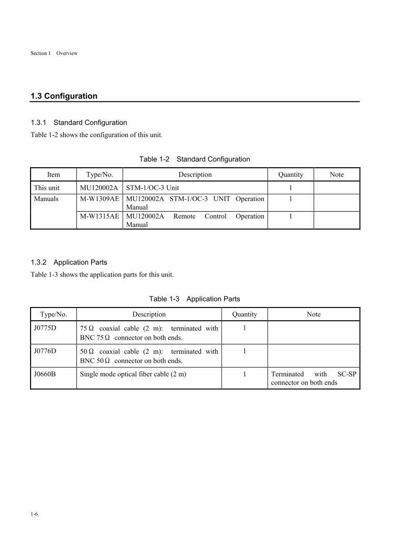
1.3 Configuration
1.3.1 Standard ConfigurationTable 1-2 shows the configuration of this unit.
Table 1-2 Standard Configuration
Item Type/No. Description Quantity Note
This unit MU120002A STM-1/OC-3 Unit 1Manuals M-W1309AE MU120002A STM-1/OC-3 UNIT Operation
Manual1
M-W1315AE MU120002A Remote Control OperationManual
1
1.3.2 Application PartsTable 1-3 shows the application parts for this unit.
Table 1-3 Application Parts
Type/No. Description Quantity Note
J0775D 75Ω coaxial cable (2 m): terminated withBNC 75Ω connector on both ends.
1
J0776D 50Ω coaxial cable (2 m): terminated withBNC 50Ω connector on both ends.
1
J0660B Single mode optical fiber cable (2 m) 1 Terminated with SC-SPconnector on both ends
Section 2 Preparation For Use
2-1
Section 2 Preparation For Use
2.1 Environmental Requirements
Avoid using this unit in the environment described below:
1. Places where temperature rises above 50ºC or falls below 5ºC or where humidity exceeds 85% or falls short of
45%.
2. Places exposed to direct sunlight or dusty place.
3. Places where dew condensation or the presence of corrosive gases are expected.
4. Places where the unit is exposed to oxidation or strong vibration.
Section 2 Preparation For Use
2-2
2.2 Safety Precautions
● Never attempt to insert the unit into the instruments other than the MP1220A ATM Quality Analyzer. The
unit is designed for use solely with the MP1220A, and any attempt to use with other instruments may cause
irreversible damage or hazards.
● Do not apply higher voltage signal than rated for this unit. This may cause circuit disruption.
● If the unit has been stored at a low temperature for a long period of time, take enough length of time for the
unit to equilibrate with ambient temperature and get thoroughly dry. Dew formation due to the lack of
temperature equilibrium may cause short circuit.
● To avoid hazards due to static discharge, be sure to connect, prior to connecting input signals, ground lines of
the instruments (including experimental ones) to be connected to the unit.
● Core and outer conductor of a coaxial cable tends to accumulate charge as a capacitor: Try to discharge using
a metal rod or the like prior to use.
Section 2 Preparation For Use
2-3
2.3 Warming Up
Warm up the MP1220A for 20 minutes or more after power-on, before performing a measurement.

Section 2 Preparation For Use
2-4.

Section 3 Description Of The Panels
3-1
Section 3 Description Of The Panels
3.1 Organization of Panels And Their Descriptions
Fig. 3-1 shows the panel of this unit, and Table 3-1 describes its functions.
MU120002A STM-1/OC-3 Unit
TrigOutput 75Ω
Rcv ClkOutput 50Ω
Ext ClkInput 50ΩOutput 75Ω Input 75Ω
(1) (3) (8)(8) (2) (4) (5) (6) (7)
CMI
Output Input
Max -8dBm -8~-29dBm
(9)
Fig. 3-1 Front Panel of MU120002A STM-1/OC-3
Table 3-1 Description of MU120002A STM-1/OC-3 Front Panel
No. Label Description
(1) Output Optical output connector (SC)
(2) Input Optical input connector (SC)
(3) CMI Output 75Ω CMI (Electrical) output connector
(4) CMI Input75 75Ω CMI (Electrical) input connector
(5) Ext Clk Input 50Ω External clock input connector (BNC)
(6) Rcv Clk Output 50Ω Received clock output connector (BNC)
(7) Trig Output 75Ω Trigger output connector (BNC)
(8) (Ejector) Ejector for pulling out the unit
(9) (LED) LED indicator. Emits light during the signal is being output.

Section 3 Description Of The Panels
3-2.
Section 4 Description Of The Screen
4-1
Section 4 Description Of The Screen
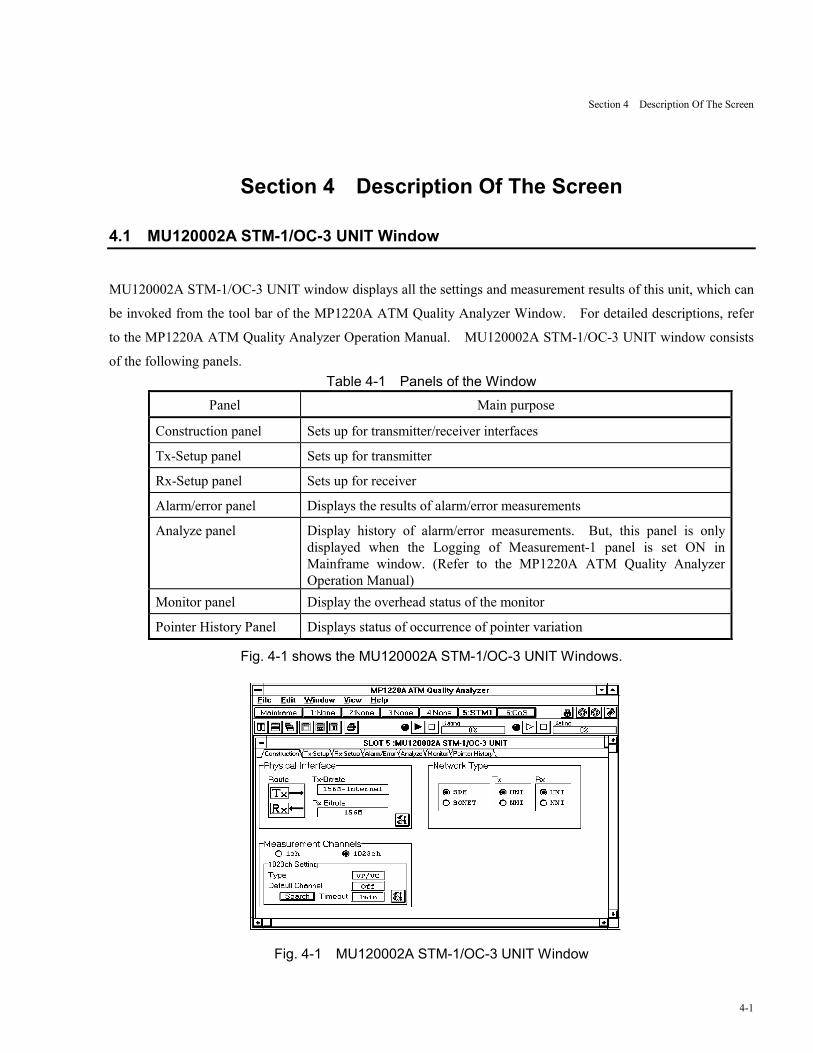
4.1 MU120002A STM-1/OC-3 UNIT Window
MU120002A STM-1/OC-3 UNIT window displays all the settings and measurement results of this unit, which can
be invoked from the tool bar of the MP1220A ATM Quality Analyzer Window. For detailed descriptions, refer
to the MP1220A ATM Quality Analyzer Operation Manual. MU120002A STM-1/OC-3 UNIT window consists
of the following panels.Table 4-1 Panels of the Window
Panel Main purpose
Construction panel Sets up for transmitter/receiver interfaces
Tx-Setup panel Sets up for transmitter
Rx-Setup panel Sets up for receiver
Alarm/error panel Displays the results of alarm/error measurements
Analyze panel Display history of alarm/error measurements. But, this panel is onlydisplayed when the Logging of Measurement-1 panel is set ON inMainframe window. (Refer to the MP1220A ATM Quality AnalyzerOperation Manual)
Monitor panel Display the overhead status of the monitor
Pointer History Panel Displays status of occurrence of pointer variation
Fig. 4-1 shows the MU120002A STM-1/OC-3 UNIT Windows.
Fig. 4-1 MU120002A STM-1/OC-3 UNIT Window
Section 4 Description Of The Screen
4-2
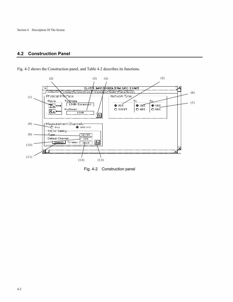
4.2 Construction Panel
Fig. 4-2 shows the Construction panel, and Table 4-2 describes its functions.
(7)
(6)
(5)(4)(3)(2)
(1)
(8)
(9)
(10)
(11)(12) (13)
Fig. 4-2 Construction panel

Section 4 Description Of The Screen
4-3
Table 4-2 Description of Construction Panel
Number Item Description
(1) Route Displays signal flow inside the unit
(2) Tx-Bitrate Displays the bit rate and type of clock in the transmission unit.
(3) Rx-Bitrate Displays the bit rate in the reception unit.
(4) Opens Physical Interface Setup dialog box
(5) SDH, SONET Sets up the frame.
(6) Tx Network type of the transmitter
(7) Rx Network type of the receiver
(8) MeasurementChannels
Sets the monitor of the band width of each channel and AIS/RDI status inATM network. (Live-Monitor measurement)The MU120020A QoS Unit and MU120021A Protocol Unit are needed forselecting “1023ch” of the Live-Monitor measurement.
1ch : Selects the monitor for 1ch.1023ch : Selects the monitor for 2ch to 1023ch at the same time.
When set “1023ch” at “Repeat” in measurement mode, thewarning dialog box appears and the setting returns to “1ch”.
(9) Type Displays the types of 1023ch measurement compatible channels.
(10) Default Channel Displays if the Default Channel settings are activated.
(11) Search If the button is pushed, 1023ch search is started.
(12) Time Out Displays the timeout for 1023ch search.
(13) Opens the Search Condition Setup dialog box. Cannot be set up duringmeasurements.
Section 4 Description Of The Screen
4-4
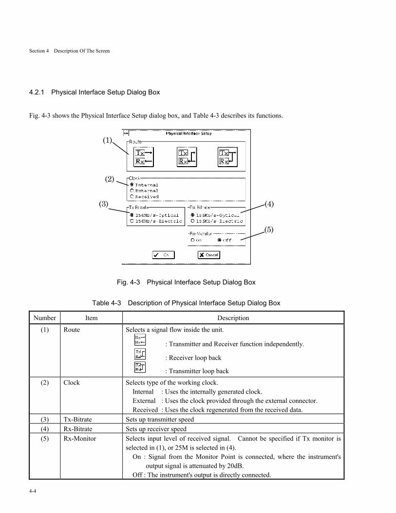
4.2.1 Physical Interface Setup Dialog Box
Fig. 4-3 shows the Physical Interface Setup dialog box, and Table 4-3 describes its functions.
(1)
(4)
(2)
(3)
(5)
Fig. 4-3 Physical Interface Setup Dialog Box
Table 4-3 Description of Physical Interface Setup Dialog Box
Number Item Description
(1) Route Selects a signal flow inside the unit.
: Transmitter and Receiver function independently.
: Receiver loop back
: Transmitter loop back
(2) Clock Selects type of the working clock.Internal : Uses the internally generated clock.External : Uses the clock provided through the external connector.Received : Uses the clock regenerated from the received data.
(3) Tx-Bitrate Sets up transmitter speed(4) Rx-Bitrate Sets up receiver speed(5) Rx-Monitor Selects input level of received signal. Cannot be specified if Tx monitor is
selected in (1), or 25M is selected in (4).On : Signal from the Monitor Point is connected, where the instrument's
output signal is attenuated by 20dB.Off : The instrument's output is directly connected.
Section 4 Description Of The Screen
4-5
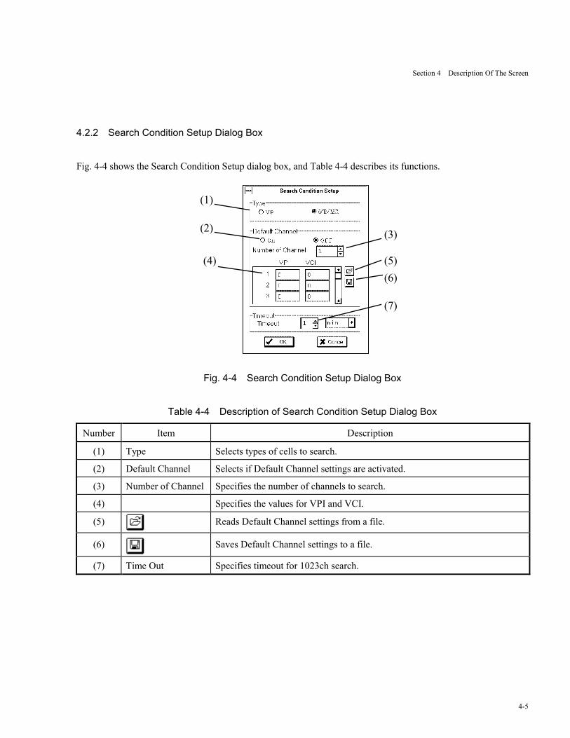
4.2.2 Search Condition Setup Dialog Box
Fig. 4-4 shows the Search Condition Setup dialog box, and Table 4-4 describes its functions.
(1)
(2) (3)
(4) (5)(6)
(7)
Fig. 4-4 Search Condition Setup Dialog Box
Table 4-4 Description of Search Condition Setup Dialog Box
Number Item Description
(1) Type Selects types of cells to search.
(2) Default Channel Selects if Default Channel settings are activated.
(3) Number of Channel Specifies the number of channels to search.
(4) Specifies the values for VPI and VCI.
(5) Reads Default Channel settings from a file.
(6) Saves Default Channel settings to a file.
(7) Time Out Specifies timeout for 1023ch search.
Section 4 Description Of The Screen
4-6
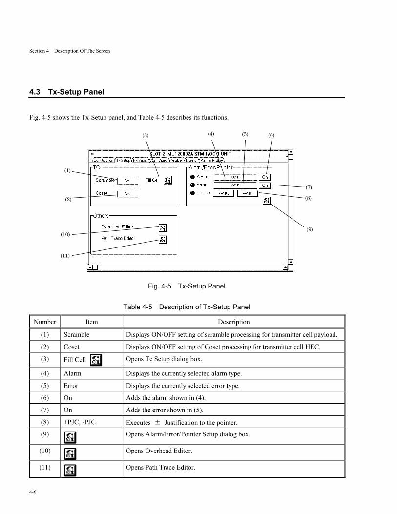
4.3 Tx-Setup Panel
Fig. 4-5 shows the Tx-Setup panel, and Table 4-5 describes its functions.
(1)
(2)
(3)
(10)
(11)
(9)
(8)
(7)
(6)(5)(4)
Fig. 4-5 Tx-Setup Panel
Table 4-5 Description of Tx-Setup Panel
Number Item Description
(1) Scramble Displays ON/OFF setting of scramble processing for transmitter cell payload.
(2) Coset Displays ON/OFF setting of Coset processing for transmitter cell HEC.
(3) Fill Cell Opens Tc Setup dialog box.
(4) Alarm Displays the currently selected alarm type.
(5) Error Displays the currently selected error type.
(6) On Adds the alarm shown in (4).
(7) On Adds the error shown in (5).
(8) +PJC, -PJC Executes ± Justification to the pointer.
(9) Opens Alarm/Error/Pointer Setup dialog box.
(10) Opens Overhead Editor.
(11) Opens Path Trace Editor.
Section 4 Description Of The Screen
4-7
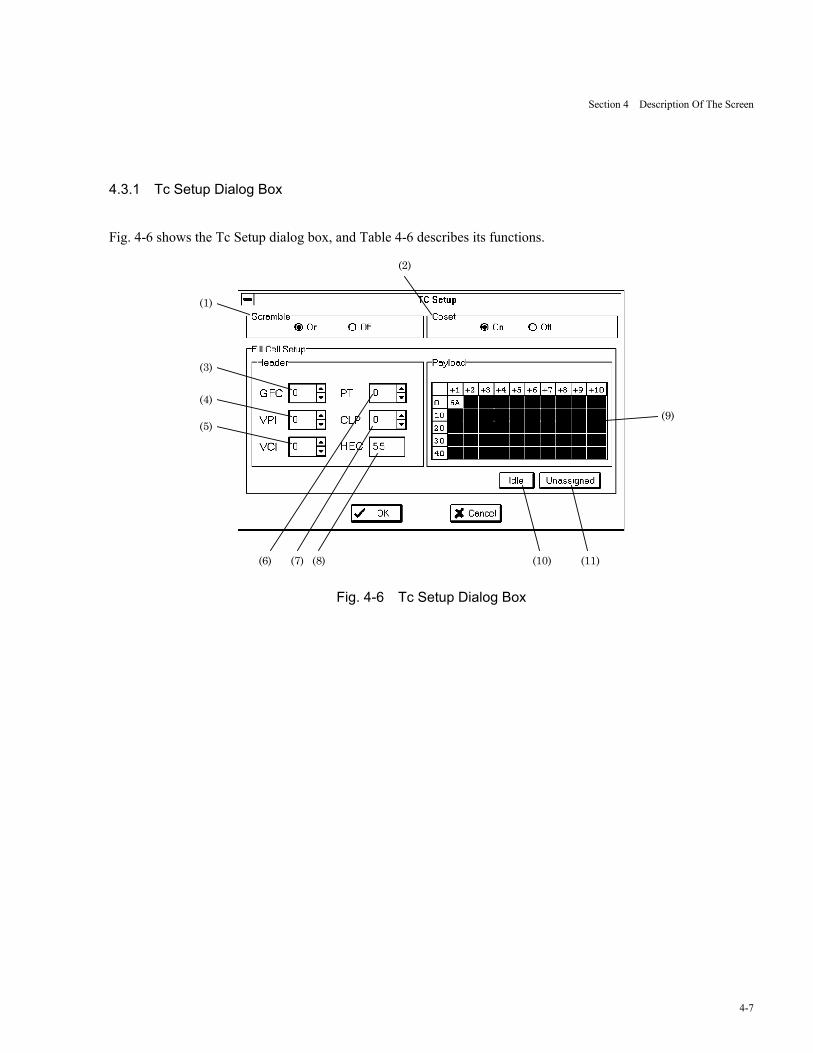
4.3.1 Tc Setup Dialog Box
Fig. 4-6 shows the Tc Setup dialog box, and Table 4-6 describes its functions.
(1)
(3)
(4)
(5)
(6) (7) (8) (10) (11)
(9)
(2)
Fig. 4-6 Tc Setup Dialog Box
Section 4 Description Of The Screen
4-8
Table 4-6 Description of Tc Setup Dialog Box
Number Item Description
(1) Scramble Selects ON/OFF setting of scramble processing for transmitter cell payload.
(2) Coset Selects ON/OFF setting of Coset processing for transmitter cell HEC.
(3) GFC Selects the GFC value. The GFC value cannot be specified if NNI is selectedin 4.2 (5).
(4) VPI Displays the VPI value (fixed to be zero).
(5) VCI Displays the VCI value (fixed to be zero).
(6) PT Specifies the PT value.
(7) CLP Specifies the CLP value.
(8) HEC Specifies the HEC value.
(9) Payload Specifies the payload value.Double click on the frame of crossing the vertical position 0 and horizontalposition +1, then Byte Setup dialog box is opened.
(10) Idle If the button is pressed, the contents of Idle cell are shown in Header andPayload group box. The contents of the Idle cell are : GFC:0, VPI:0, VCI:0,PT:0, CLP:1, HEC : calculated value, Payload:6A.
(11) Unassigned If the button is pressed, the contents of Unassigned cell are shown in Headerand Payload group box. The contents of the Unassigned cell are : GFC:0,VPI:0, VCI:0, PT:0, CLP:0, HEC : calculated value, Payload:6A.
Section 4 Description Of The Screen
4-9
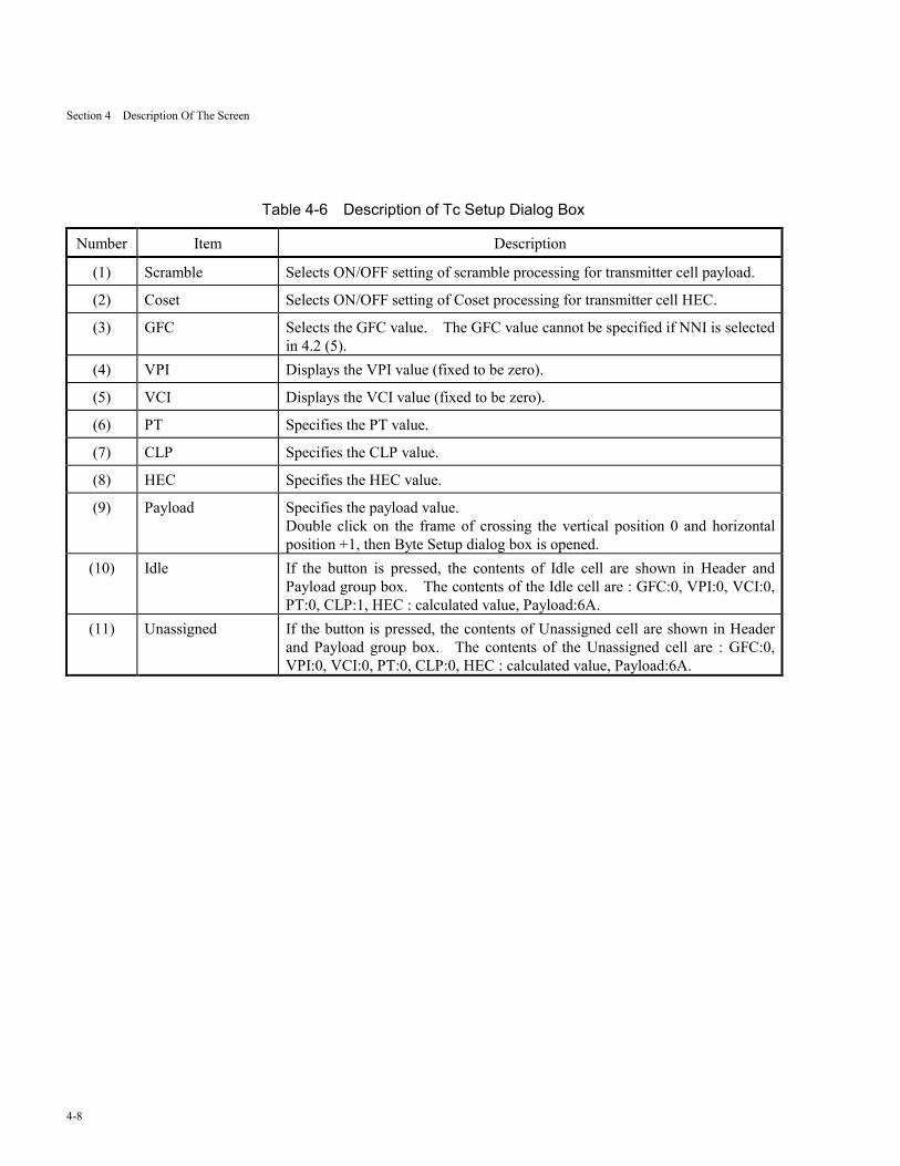
4.3.1.1 Byte Setup dialog box
Fig. 4-7 shows the Byte Setup dialog box, and Table 4-7 describes its functions.
(1)
Fig. 4-7 Byte Setup Dialog Box
Table 4-7 Description of Byte Setup Dialog Box
Number Item Description
(1) Specifies the payload value.48 bytes are the same value as bite unit.

Section 4 Description Of The Screen
4-10
4.3.2 Alarm/Error/Pointer Setup Dialog Box
4.3.2.1 Alarm panel
Fig. 4-8 shows the Alarm panel, and Table 4-8 describes its functions.
(1)
Fig. 4-8 Alarm Panel
Table 4-8 Description of Alarm Panel
Number Item Description
(1) Type Selects the type of alarms to add.
Section 4 Description Of The Screen
4-11
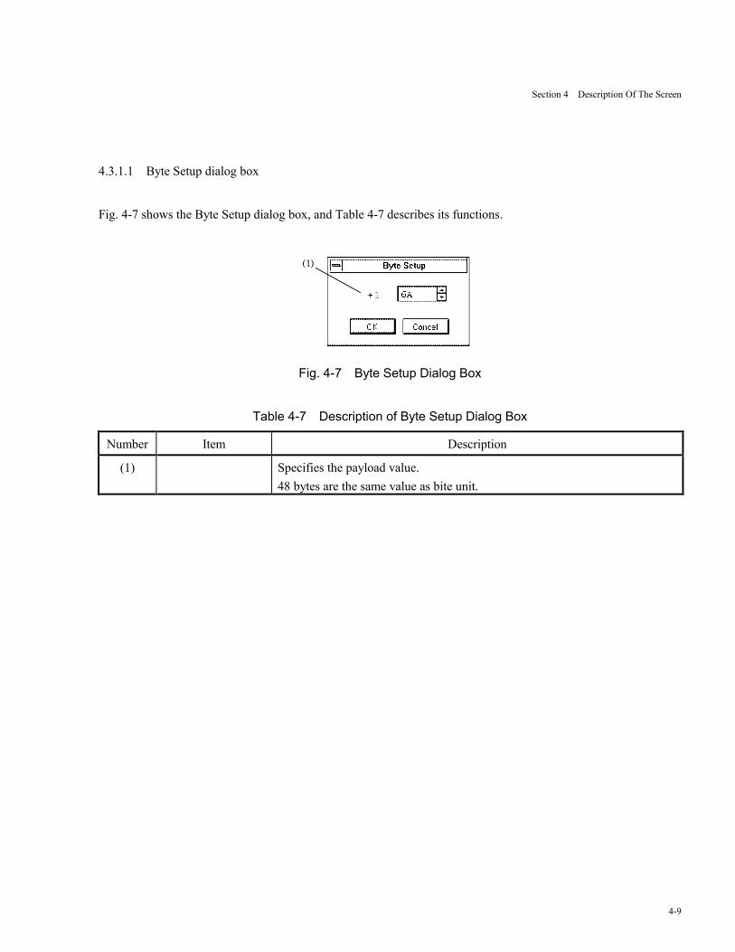
4.3.2.2 Error Panel
Fig. 4-9 shows Error panel, and Table 4-9 describes its functions.
(1) (2)
(3)
(4)
(5)
Fig. 4-9 Error Panel
Table 4-9 Description of Error Panel
Number Item Description
(1) Type Selects the type of errors to add. If Cell is selected, When Bit has beenselected in the Setup screen of the MU120020A QoS Unit or MU120021AProtocol Unit, the selection of Cell will display a warning dialog and promptuser's confirmation.
(2) Period Specifies the number of contiguous cells to add error. Specify a desiredvalue (1 to 64); the value can only be set if Cell is selected in (1).
(3) Position Specifies the byte position of the cell to be bit-reversed.The value can only be set if Cell is selected in (1).
(4) Bit Specifies the bit to be reversed.This selection can be made only if Cell is selected in (1).
(5) Rate Selects the timing of error addition.The options are: Single, All, Rate (1E-n, n=3,4,5,6,7,8,9).
Section 4 Description Of The Screen
4-12
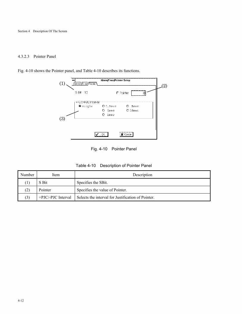
4.3.2.3 Pointer Panel
Fig. 4-10 shows the Pointer panel, and Table 4-10 describes its functions.
(1) (2)
(3)
Fig. 4-10 Pointer Panel
Table 4-10 Description of Pointer Panel
Number Item Description
(1) S Bit Specifies the SBit.
(2) Pointer Specifies the value of Pointer.
(3) +PJC/-PJC Interval Selects the interval for Justification of Pointer.
Section 4 Description Of The Screen
4-13
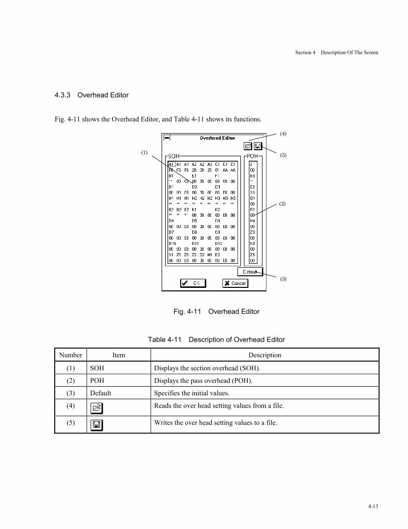
4.3.3 Overhead Editor
Fig. 4-11 shows the Overhead Editor, and Table 4-11 shows its functions.
(1)
(3)
(2)
(5)
(4)
Fig. 4-11 Overhead Editor
Table 4-11 Description of Overhead Editor
Number Item Description
(1) SOH Displays the section overhead (SOH).
(2) POH Displays the pass overhead (POH).
(3) Default Specifies the initial values.
(4) Reads the over head setting values from a file.
(5) Writes the over head setting values to a file.

Section 4 Description Of The Screen
4-14
4.3.3.1 Byte Setup Dialog Box
Fig. 4-12 shows the Byte Setup dialog box, and Table 4-12 describes its functions.
(1)
Fig. 4-12 Byte Setup Dialog Box
Table 4-12 Description of Byte Setup Dialog Box
Number Item Description
(1) Sets up SOH, POH

Section 4 Description Of The Screen
4-15
4.3.4 Path Trace Editor (J0, J1)
Fig. 4-13 shows the Path Trace Editor (J0, J1), and Table 4-13 describes its functions.
(1)
(2)
(3)
(4)
Fig. 4-13 Path Trace Editor (J0, J1)
Table 4-13 Description of Path Trace Editor (J0, J1)
Number Item Description
(1) On/Off Selects ON/OFF for Path Trace submission.
(2) Displays the Path Trace settings.
(3) ORC-7 Selects ON/OFF for CRC-7 addition.
(4) HEX/ASCII Selects types of Path Trace setting.
Section 4 Description Of The Screen
4-16
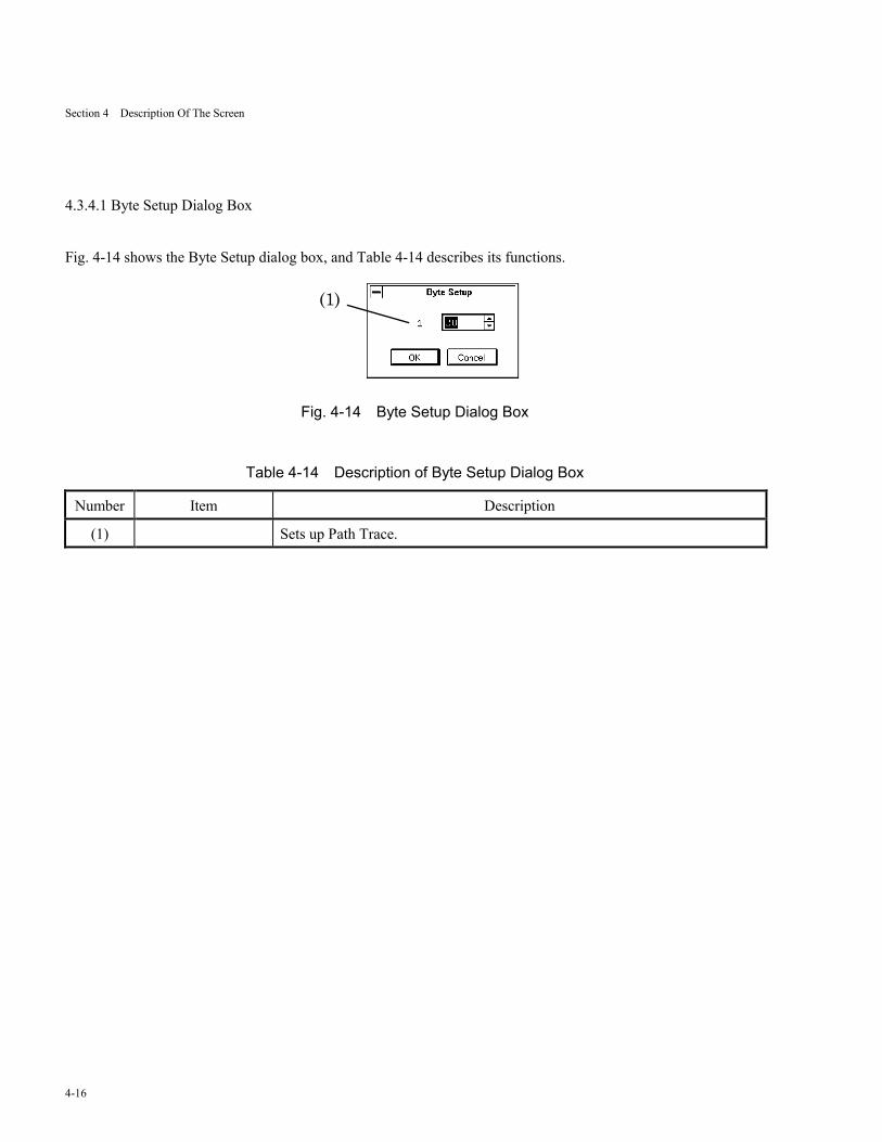
4.3.4.1 Byte Setup Dialog Box
Fig. 4-14 shows the Byte Setup dialog box, and Table 4-14 describes its functions.
(1)
Fig. 4-14 Byte Setup Dialog Box
Table 4-14 Description of Byte Setup Dialog Box
Number Item Description
(1) Sets up Path Trace.
Section 4 Description Of The Screen
4-17
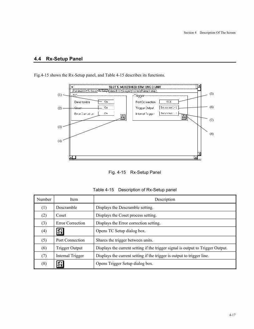
4.4 Rx-Setup Panel
Fig.4-15 shows the Rx-Setup panel, and Table 4-15 describes its functions.
(1)
(2)
(3)
(4)
(5)
(6)
(7)
(8)
Fig. 4-15 Rx-Setup Panel
Table 4-15 Description of Rx-Setup panel
Number Item Description
(1) Descramble Displays the Descramble setting.
(2) Coset Displays the Coset process setting.
(3) Error Correction Displays the Error correction setting.
(4) Opens TC Setup dialog box.
(5) Port Connection Shares the trigger between units.
(6) Trigger Output Displays the current setting if the trigger signal is output to Trigger Output.
(7) Internal Trigger Displays the current setting if the trigger is output to trigger line.
(8) Opens Trigger Setup dialog box.

Section 4 Description Of The Screen
4-18
4.4.1 TC Setup Dialog Box
Fig. 4-16 shows the TC Setup dialog box, and Table 4-16 describes its functions.
(1)(2)
(3)
Fig. 4-16 TC Setup Dialog Box
Table 4-16 Description of TC Setup Dialog Box
Number Item Description
(1) Descramble Selects ON/OFF of descrambling for receiving cell payload.
(2) Coset Selects ON/OFF of Coset processing for receiving cell HEC.
(3) Error Correction Selects ON/OFF of HEC correction for receiving cell.
Section 4 Description Of The Screen
4-19
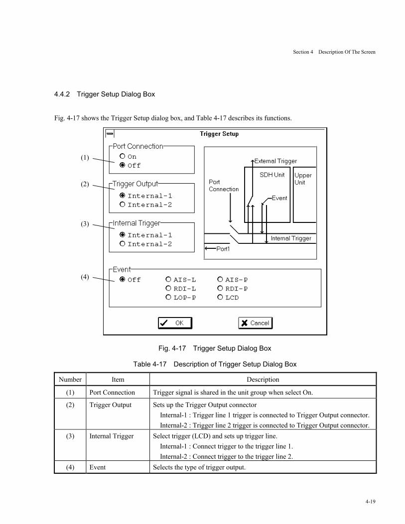
4.4.2 Trigger Setup Dialog Box
Fig. 4-17 shows the Trigger Setup dialog box, and Table 4-17 describes its functions.
Fig. 4-17 Trigger Setup Dialog Box
Table 4-17 Description of Trigger Setup Dialog Box
Number Item Description
(1) Port Connection Trigger signal is shared in the unit group when select On.
(2) Trigger Output Sets up the Trigger Output connectorInternal-1 : Trigger line 1 trigger is connected to Trigger Output connector.Internal-2 : Trigger line 2 trigger is connected to Trigger Output connector.
(3) Internal Trigger Select trigger (LCD) and sets up trigger line.Internal-1 : Connect trigger to the trigger line 1.Internal-2 : Connect trigger to the trigger line 2.
(4) Event Selects the type of trigger output.
(1)
(2)
(3)
(4)
Section 4 Description Of The Screen
4-20
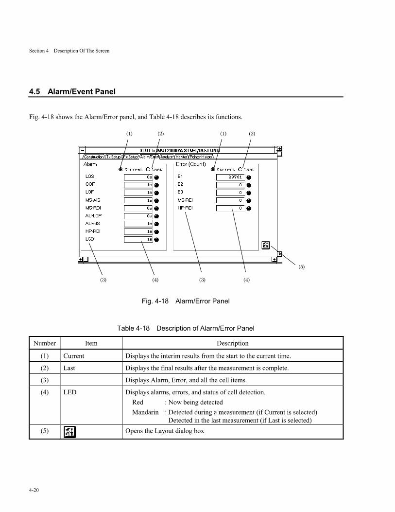
4.5 Alarm/Event Panel
Fig. 4-18 shows the Alarm/Error panel, and Table 4-18 describes its functions.
(3)(3) (4) (4)
(1) (2) (1) (2)
(5)
Fig. 4-18 Alarm/Error Panel
Table 4-18 Description of Alarm/Error Panel
Number Item Description
(1) Current Displays the interim results from the start to the current time.
(2) Last Displays the final results after the measurement is complete.
(3) Displays Alarm, Error, and all the cell items.
(4) LED Displays alarms, errors, and status of cell detection.Red : Now being detectedMandarin : Detected during a measurement (if Current is selected)
Detected in the last measurement (if Last is selected)(5) Opens the Layout dialog box
Section 4 Description Of The Screen
4-21
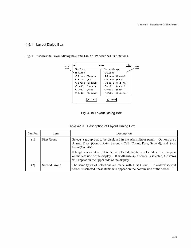
4.5.1 Layout Dialog Box
Fig. 4-19 shows the Layout dialog box, and Table 4-19 describes its functions.
(1) (2)
Fig. 4-19 Layout Dialog Box
Table 4-19 Description of Layout Dialog Box
Number Item Description
(1) First Group Selects a group box to be displayed in the Alarm/Error panel. Options are :Alarm, Error (Count, Rate, Second), Cell (Count, Rate, Second), and SyncEvent(Count/s).If lengthwise-split or full screen is selected, the items selected here will appearon the left side of the display. If widthwise-split screen is selected, the itemswill appear on the upper side of the display.
(2) Second Group The same types of selections are made with First Group. If widthwise-splitscreen is selected, these items will appear on the bottom side of the screen.
Section 4 Description Of The Screen
4-22
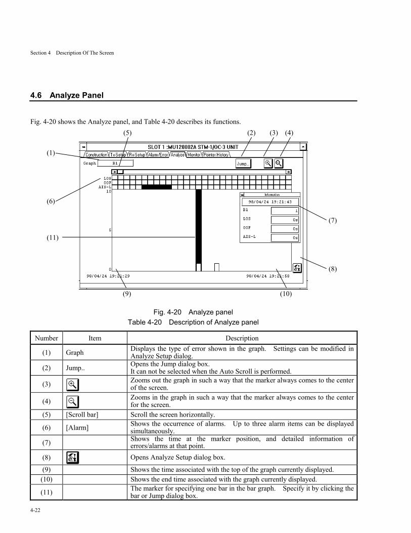
4.6 Analyze Panel
Fig. 4-20 shows the Analyze panel, and Table 4-20 describes its functions.
Fig. 4-20 Analyze panelTable 4-20 Description of Analyze panel
Number Item Description
(1) Graph Displays the type of error shown in the graph. Settings can be modified inAnalyze Setup dialog.
(2) Jump.. Opens the Jump dialog box.It can not be selected when the Auto Scroll is performed.
(3) Zooms out the graph in such a way that the marker always comes to the centerof the screen.
(4) Zooms in the graph in such a way that the marker always comes to the centerfor the screen.
(5) [Scroll bar] Scroll the screen horizontally.
(6) [Alarm] Shows the occurrence of alarms. Up to three alarm items can be displayedsimultaneously.
(7) Shows the time at the marker position, and detailed information oferrors/alarms at that point.
(8) Opens Analyze Setup dialog box.
(9) Shows the time associated with the top of the graph currently displayed.(10) Shows the end time associated with the graph currently displayed.
(11) The marker for specifying one bar in the bar graph. Specify it by clicking thebar or Jump dialog box.
(5) (2) (3) (4)
(9) (10)
(7)
(8)
(1)
(6)
(11)
Section 4 Description Of The Screen
4-23
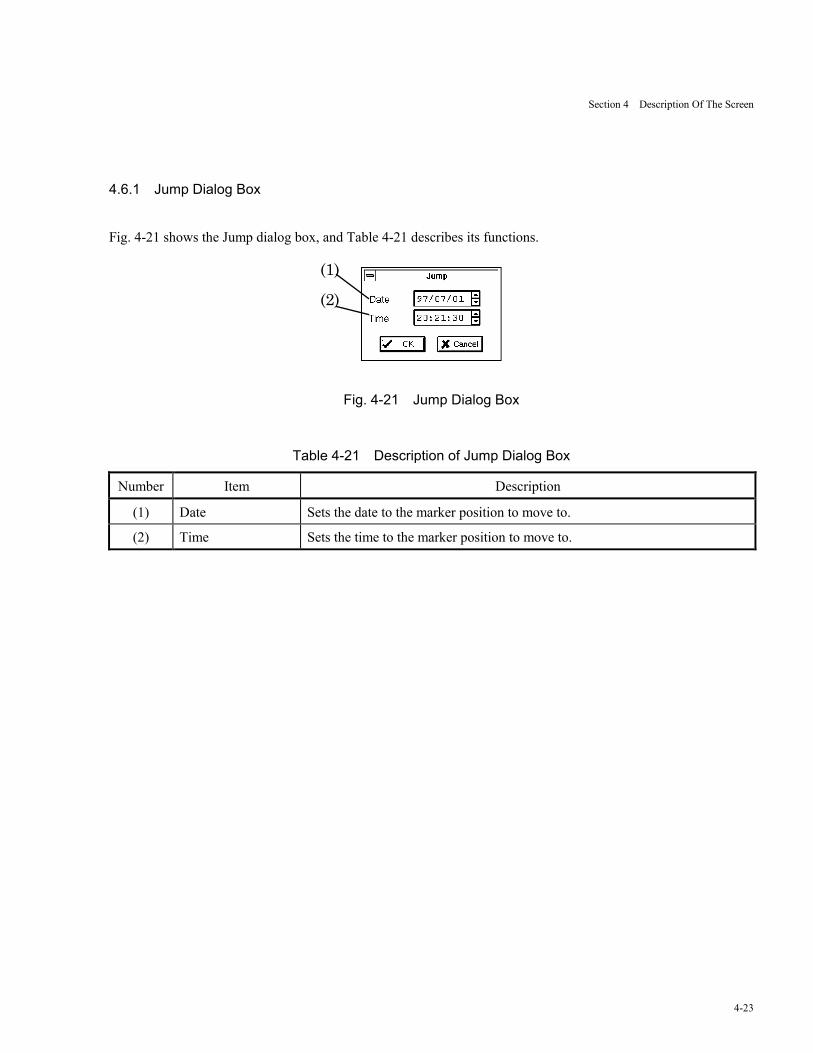
4.6.1 Jump Dialog Box
Fig. 4-21 shows the Jump dialog box, and Table 4-21 describes its functions.
(1)
(2)
Fig. 4-21 Jump Dialog Box
Table 4-21 Description of Jump Dialog Box
Number Item Description
(1) Date Sets the date to the marker position to move to.
(2) Time Sets the time to the marker position to move to.
Section 4 Description Of The Screen
4-24
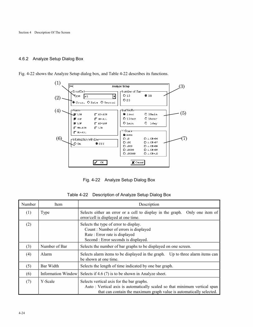
4.6.2 Analyze Setup Dialog Box
Fig. 4-22 shows the Analyze Setup dialog box, and Table 4-22 describes its functions.
(1)
(4)
(3)
(6)
(5)
(2)
(7)
Fig. 4-22 Analyze Setup Dialog Box
Table 4-22 Description of Analyze Setup Dialog Box
Number Item Description
(1) Type Selects either an error or a cell to display in the graph. Only one item oferror/cell is displayed at one time.
(2) Selects the type of error to display.Count : Number of errors is displayedRate : Error rate is displayedSecond : Error seconds is displayed.
(3) Number of Bar Selects the number of bar graphs to be displayed on one screen.
(4) Alarm Selects alarm items to be displayed in the graph. Up to three alarm items canbe shown at one time.
(5) Bar Width Selects the length of time indicated by one bar graph.
(6) Information Window Selects if 4.6 (7) is to be shown in Analyze sheet.
(7) Y-Scale Selects vertical axis for the bar graphs.Auto : Vertical axis is automatically scaled so that minimum vertical span
that can contain the maximum graph value is automatically selected.
Section 4 Description Of The Screen
4-25
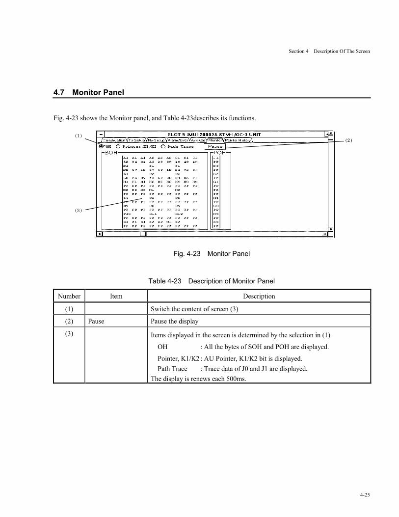
4.7 Monitor Panel
Fig. 4-23 shows the Monitor panel, and Table 4-23describes its functions.
(2 )(1 )
(3 )
Fig. 4-23 Monitor Panel
Table 4-23 Description of Monitor Panel
Number Item Description
(1) Switch the content of screen (3)
(2) Pause Pause the display
(3) Items displayed in the screen is determined by the selection in (1)
OH : All the bytes of SOH and POH are displayed.
Pointer, K1/K2 : AU Pointer, K1/K2 bit is displayed.Path Trace : Trace data of J0 and J1 are displayed.
The display is renews each 500ms.
Section 4 Description Of The Screen
4-26
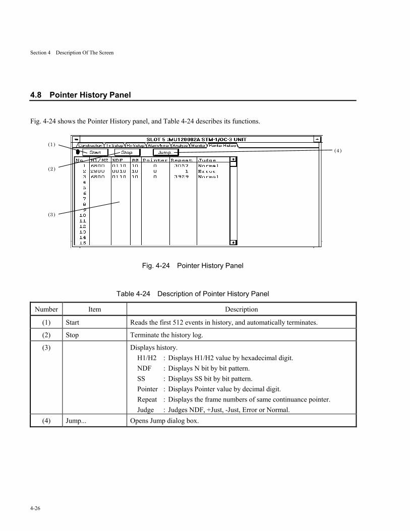
4.8 Pointer History Panel
Fig. 4-24 shows the Pointer History panel, and Table 4-24 describes its functions.
(1 )
(2 )
(3 )
(4 )
Fig. 4-24 Pointer History Panel
Table 4-24 Description of Pointer History Panel
Number Item Description
(1) Start Reads the first 512 events in history, and automatically terminates.
(2) Stop Terminate the history log.
(3) Displays history.H1/H2 : Displays H1/H2 value by hexadecimal digit.NDF : Displays N bit by bit pattern.SS : Displays SS bit by bit pattern.Pointer : Displays Pointer value by decimal digit.Repeat : Displays the frame numbers of same continuance pointer.Judge : Judges NDF, +Just, -Just, Error or Normal.
(4) Jump... Opens Jump dialog box.
Section 4 Description Of The Screen
4-27
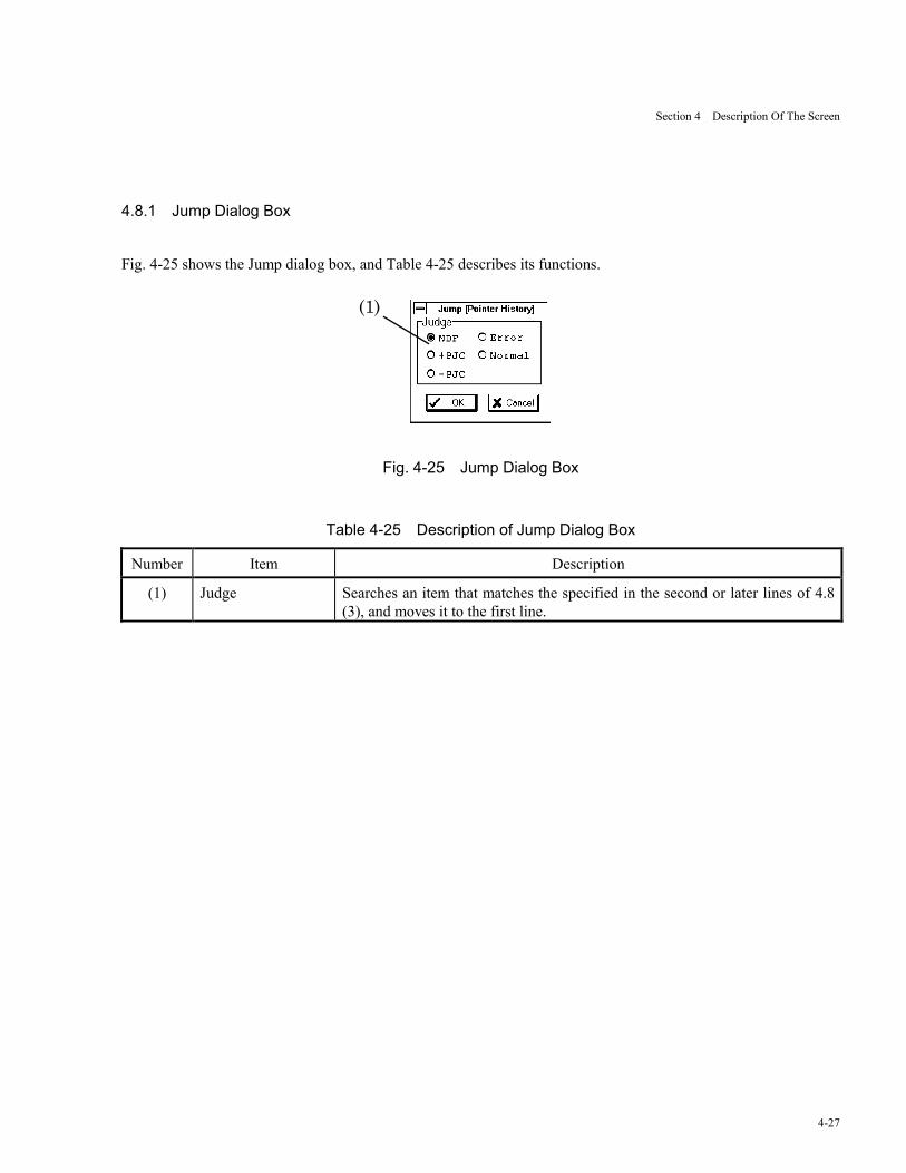
4.8.1 Jump Dialog Box
Fig. 4-25 shows the Jump dialog box, and Table 4-25 describes its functions.
(1)
Fig. 4-25 Jump Dialog Box
Table 4-25 Description of Jump Dialog Box
Number Item Description
(1) Judge Searches an item that matches the specified in the second or later lines of 4.8(3), and moves it to the first line.

Section 4 Description Of The Screen
4-28.

Section 5 Measurement
5-1
Section 5 Measurement
5.1 Performance Measurement
1. Connection
Connect the system as shown in Fig. 5-1, and turn the power on.
ATM quality analyzer (rear view)
Printer
6
5
4
3
2
1
!CAUTION FOR CONTINUED FIRE PROTECTION REPLACEONLY WITH SPECIFIED TYPE RATED FUSE.
WARNING NO OPERATOR SERVICEABLE PARTS INSED.REFER SERVICING TO QUALIFIED PERSONEL.
!
~Line Input47.5-63Hz,300VA Max
AC 100-120/200-240V, T 3.15A
MU120020A QoS UNIT
MU120002A STM-1/OC-3 UNIT
DSU
SLI
Fig. 5-1 Connection for Performance Measurement
2. Physical Interface SettingsOpen the Physical Interface dialog box under Physical Interface group box in the Construction panel.Specify physical interface settings as follows:
Route : Clock : InternalTx-Bitrate : 156Mb/sRx-Bitrate : 156Mb/s
3. Results of measurementOpen the Layout dialog box in the Alarm/Error panel. Select Error (Count), Error (Rate), or Error (Second) ineither First Group or Second Group group boxes.Push the start button (Go button) to start measurement, and the result will be displayed in the Alarm/Error panel.Either intermediate, or final results will be displayed by selecting Current or Last.
4. AnalyzeIf the use of the log file had been specified in the main frame, the user has an access, by opening an Analyzesheet, to the information concerning the time and frequency of error occurrence.

Section 5 Measurement
5-2.
Section 6 Performance Test
6-1
Section 6 Performance Test
6.1 About Performance Tests
This Section describe how to carry out performance tests to make certain that the unit is working properly. For
detailed procedures to insert the unit to the main frame, to turn on power, and to open the MU120002A STM-
1/OC-3 Unit windows, refer to the MP1220A ATM Quality Analyzer Operation Manual.
A performance test sheet is contained in Appendix A.
Section 6 Performance Test
6-2.
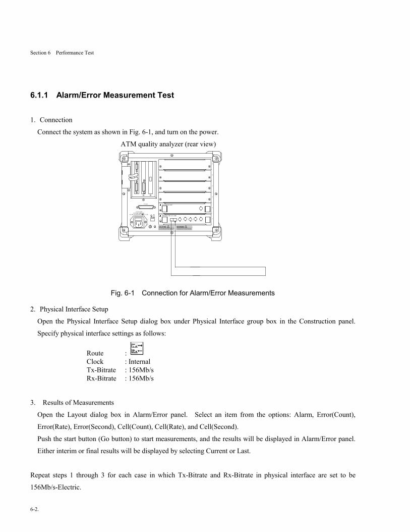
6.1.1 Alarm/Error Measurement Test
1. Connection
Connect the system as shown in Fig. 6-1, and turn on the power.
ATM quality analyzer (rear view)
Printer
6
5
4
3
2
1
!CAUTION FOR CONTINUED FIRE PROTECTION REPLACEONLY WITH SPECIFIED TYPE RATED FUSE.
WARNING NO OPERATOR SERVICEABLE PARTS INSED.REFER SERVICING TO QUALIFIED PERSONEL.
!
~Line Input47.5-63Hz,300VA Max
AC 100-120/200-240V, T 3.15A
MU120020A QoS UNIT
MU120002A STM-1/OC-3 UNIT
Fig. 6-1 Connection for Alarm/Error Measurements
2. Physical Interface Setup
Open the Physical Interface Setup dialog box under Physical Interface group box in the Construction panel.
Specify physical interface settings as follows:
Route : Clock : InternalTx-Bitrate : 156Mb/sRx-Bitrate : 156Mb/s
3. Results of Measurements
Open the Layout dialog box in Alarm/Error panel. Select an item from the options: Alarm, Error(Count),
Error(Rate), Error(Second), Cell(Count), Cell(Rate), and Cell(Second).
Push the start button (Go button) to start measurements, and the results will be displayed in Alarm/Error panel.
Either interim or final results will be displayed by selecting Current or Last.
Repeat steps 1 through 3 for each case in which Tx-Bitrate and Rx-Bitrate in physical interface are set to be
156Mb/s-Electric.
Section 7 Maintenance
7-1
Section 7 Maintenance
7.1 Daily Maintenance
1. Wipe dirt off the instrument with a cloth and diluted synthetic detergent.
2. Suck dust with a vacuum cleaner.
3. If any part is found loose, use the dedicated tool to tighten it.
Section 7 Maintenance
7-2
7.2 Notes on Storage
For a prolonged storage of the instrument, pay attention to the followings:
1. Remove dust and dirt from the instrument prior to storage.
2. Avoid storage in the place where temperature rises above 60℃, or falls below -20℃.
3. Avoid prolonged storage in a place where the sun directly hits the instrument, or dust may accumulate.
4. Avoid prolonged storage in a place exposed to direct sunlight or with much dust.
5. Avoid storage in a place where the instrument is exposed to oxidation or strong vibration.
Section 7 Maintenance
7-3
7.3 Transportation
If the packing materials used for factory shipping have been preserved, do use them for the transportation of the
instrument. Otherwise, follow the packaging procedures described below. Do not fail to wear a clean pair of
gloves, and handle the instrument with care to avoid making scars or bruises on the surface.
1. Clean dirt and dust off the instrument's surface with a dry cloth.
2. Check if any part is missing or have become loose.
3. Protruding or damage-prone portion should be carefully protected. Wrap the instrument with sheets of
polyethylene, and furthermore with sheets of moisture proof paper.
4. Place the wrapped instrument inside a cardboard box and seal the box with masking tapes. Transportation
distance and method may necessitate the use of a cart box for protection.
Section 7 Maintenance
7-4.
7.4 Calibration
This instrument can only be calibrated by the manufacturer. Periodical calibration is recommended to maintain
utmost performance.
Appendix A Performance Test Sheet
A-1
Appendix
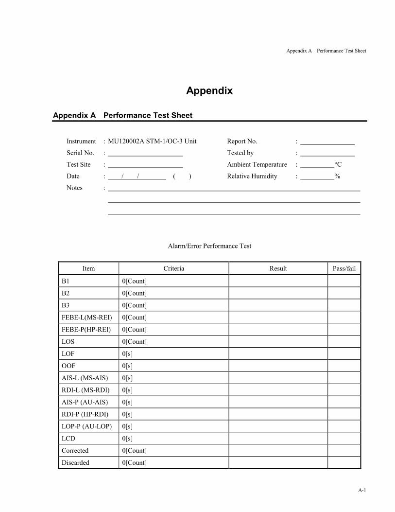
Appendix A Performance Test Sheet
Instrument : MU120002A STM-1/OC-3 Unit Report No. :
Serial No. : Tested by :
Test Site : Ambient Temperature : �C
Date : / / ( ) Relative Humidity : %
Notes :
Alarm/Error Performance Test
Item Criteria Result Pass/fail
B1 0[Count]
B2 0[Count]
B3 0[Count]
FEBE-L(MS-REI) 0[Count]
FEBE-P(HP-REI) 0[Count]
LOS 0[Count]
LOF 0[s]
OOF 0[s]
AIS-L (MS-AIS) 0[s]
RDI-L (MS-RDI) 0[s]
AIS-P (AU-AIS) 0[s]
RDI-P (HP-RDI) 0[s]
LOP-P (AU-LOP) 0[s]
LCD 0[s]
Corrected 0[Count]
Discarded 0[Count]

Appendix A Performance Test Sheet
A-2.
Index
I-1
Index
M
MU12002A STM-1/OC-3 unit ・・・・・・・・・・・・・・・・・・・・・・・・・・・・・・・・・・・・・・・・・・・・・・・・・・・・・・・・・・・・・ v, 1-1
R
Reception loopback ・・・・・・・・・・・・・・・・・・・・・・・・・・・・・・・・・・・・・・・・・・・・・・・・・・・・・・・・・・・・・・・・・・・・・・・・ 1-1
T
Transmission loopback ・・・・・・・・・・・・・・・・・・・・・・・・・・・・・・・・・・・・・・・・・・・・・・・・・・・・・・・・・・・・・・・・・・ 1-1, 1-2

Index
I-2.