Mtr (50) single and Dual DC-DC...
20
FEATURES • Input voltage range 16 to 50 volts • Transient protection up to 80 volts per MIL-STD-704A • Operating temperature -55°C to +125°C • Fully isolated, magnetic feedback • Fixed high frequency switching • Inhibit and synchronization function • Indefinite short circuit and overload protection DESCRIPTION The Interpoint® MTR Series™ of dc-dc converters offers up to 30 watts of output power from single or dual output configurations. MTR (50) models have a wide input voltage range of 16 to 50 volts. Transient protection of up to 80 volts input meets the transient requirements of MIL-STD-704A. The converters operate over the full military temperature range with up to 81% efficiency. MTR converters are packaged in hermetically sealed metal cases, making them ideal for use in military, aerospace and other high reliability applications. The converters are offered with standard screening, “ES” screening, or fully compliant to “883” MIL-PRF-38534 Class H screening. See Table 9 on page 19 and Table 10 on page 20. Standard microcircuit drawings (SMD) are available refer to Table 3 on page 6. COVER MARKING The cover marking for the MTR 50 has “MTR (50) DC-DC CONVERTER” below the model number. Refer to Figure 8 on page 6. CONVERTER DESIGN The MTR converters are constant frequency, pulse-width modulated switching regulators which use a quasi-square wave, single ended, forward converter design. Tight load regulation is maintained via wide bandwidth magnetic feedback and, on single output models, through use of remote sense. On dual output models, the positive output is independently regulated and the negative output is cross regulated through the use of tightly coupled magnetics. Indefinite short circuit protection and overload protection are provided by a constant current-limit feature. This protective system senses current in the converter’s secondary stage and limits it to approximately 140% of the maximum rated output current. MTR converters are provided with internal filtering capacitors that help reduce the need for external components in normal operation. Use our FMCE-0328™, FMCE-0528™ or FMCE- 0828™ EMI filter to meet the requirements of MIL-STD-461C CE03 and CS01 and/or MIL-STD-461D, E and F CE102 and CS101 levels of conducted emissions. MODELS OUTPUT VOLTAGE (V) SINGLE DUAL 3.3 ±5 5 ±12 8.5 ±15 12 15 LEGACY MTR (40): 16 - 40 Vin, 50 V transient / 50 ms. Datasheet at www.interpoint.com/mtr40 Crane Aerospace & Electronics Power Solutions MTR (50) Single and Dual DC-DC Converters Page 1 of 20 28 (16-50) VOLT INPUT – 30 WATT MTR-02 Rev AE - 2016.04.26 Crane Aerospace & Electronics Power Solutions – Interpoint Products 10301 Willows Rd. NE, Redmond, WA 98052 +1 425-882-3100 • [email protected] www.craneae.com/interpoint
-
Upload
nguyendien -
Category
Documents
-
view
218 -
download
2
Transcript of Mtr (50) single and Dual DC-DC...

Features• Inputvoltagerange16to50volts• Transientprotectionupto80volts
perMIL-STD-704A• Operatingtemperature-55°Cto+125°C• Fullyisolated,magneticfeedback• Fixedhighfrequencyswitching• Inhibitandsynchronizationfunction• Indefiniteshortcircuitandoverloadprotection
DesCrIPtIONTheInterpoint®MTRSeries™ofdc-dcconvertersoffersupto30wattsofoutputpowerfromsingleordualoutputconfigurations.MTR(50)modelshaveawideinputvoltagerangeof16to50volts.Transientprotectionofupto80voltsinputmeetsthetransientrequirementsofMIL-STD-704A.Theconvertersoperateoverthefullmilitarytemperaturerangewithupto81%efficiency.MTRconvertersarepackagedinhermeticallysealedmetalcases,makingthemidealforuseinmilitary,aerospaceandotherhighreliabilityapplications.Theconvertersareofferedwithstandardscreening,“ES”screening,orfullycompliantto“883”MIL-PRF-38534ClassHscreening.SeeTable9onpage19andTable10onpage20.Standardmicrocircuitdrawings(SMD)areavailablerefertoTable3onpage6.
Cover MarkingThecovermarkingfortheMTR50has“MTR(50)DC-DCCONVERTER”belowthemodelnumber.RefertoFigure8onpage6.
Converter DesignTheMTRconvertersareconstantfrequency,pulse-widthmodulatedswitchingregulatorswhichuseaquasi-squarewave,singleended,forwardconverterdesign.Tightloadregulationismaintainedviawidebandwidthmagneticfeedbackand,onsingleoutputmodels,throughuseofremotesense.Ondualoutputmodels,thepositiveoutputisindependentlyregulatedandthenegativeoutputiscrossregulatedthroughtheuseoftightlycoupledmagnetics.
Indefiniteshortcircuitprotectionandoverloadprotectionareprovidedbyaconstantcurrent-limitfeature.Thisprotectivesystemsensescurrentintheconverter’ssecondarystageandlimitsittoapproximately140%ofthemaximumratedoutputcurrent.
MTRconvertersareprovidedwithinternalfilteringcapacitorsthathelpreducetheneedforexternalcomponentsinnormaloperation.UseourFMCE-0328™,FMCE-0528™orFMCE-0828™EMIfiltertomeettherequirementsofMIL-STD-461CCE03andCS01and/orMIL-STD-461D,EandFCE102andCS101levelsofconductedemissions.
MODELSOutput VOltage (V)
SINGLE DUAL3.3 ±55 ±128.5 ±151215
LegaCy Mtr (40):16-40Vin,50Vtransient/50ms.Datasheetatwww.interpoint.com/mtr40
Crane Aerospace & Electronics Power Solutions
Mtr (50) single and Dual DC-DC Converters
Page1of20
28 (16-50) VOlt INPut – 30 Watt
MTR-02RevAE-2016.04.26Crane Aerospace & ElectronicsPower Solutions – Interpoint Products10301 Willows Rd. NE, Redmond, WA 98052+1 425-882-3100 • [email protected]/interpoint

synChronizationSynchronizingtheconverterwiththesystemclockallowsthedesignertoconfineswitchingnoisetoclocktransitions,minimizinginterferenceandreducingtheneedforfiltering.Insyncmode,theconverterwillrunatanyfrequencybetween500kHzand675kHz.Thesynccontroloperateswithadutycyclebetween40%and60%.Thesyncpinmustbeconnectedtoinputcommonpinwhennotinuse.
DynaMiC responseTheMTRSeriesfeed-forwardcompensationsystemprovidesexcellentdynamicresponseandnoiserejection.Audiorejectionistypically40dB.Theminimumtomaximumsteplinetransitionresponseistypicallylessthan4%.
inhibit FunCtionMTRSeriesconvertersprovideaninhibitterminalthatcanbeusedtodisableinternalswitching,resultinginnooutputvoltageandverylowquiescentinputcurrent.Theconverterisinhibitedwhentheinhibitpinispulledbelow0.8voltsandenabledwhenitsinhibitpinisleftfloating.Anexternalinhibitinterfaceshouldbecapableofpullingtheconverter’sinhibitpinbelow0.8voltswhilesinkingthemaximuminhibitcurrentandalsoallowingtheinhibitpintofloathightoenabletheconverter.Avoltageshouldnotbeappliedtotheinhibitpin.Theopencircuitvoltagepresentontheinhibitpinis9to11volts
Figure 1: Mtr singLe bLoCk DiagraM
OutputCommon
PositiveOutput
PositiveInput
Inhibit
InputCommon
InputCommon
InputCommon
Sync In
MTR Single Output
Input Filter
DriverPWM
Case
VBIAS
RSENSE
Current Limit VoltageFeedback
Crane Aerospace & Electronics Power Solutions
Mtr (50) single and Dual DC-DC Converters28 (16-50) VOlt INPut – 30 Watt
www.craneae.com/interpoint Page2of20MTR-02RevAE-2016.04.26

Figure 2: Mtr DuaL bLoCk DiagraM
InputCommon
InputCommon
MTR Series Dual Output /883
Input Filter
Driver
L2 A
L2 B
OutputCommon
OutputCommon
PositiveOutput
Negative Output
PositiveInput
Inhibit
Sync
InputCommon
Case
OutputCommon
PWM
VBIAS
Current Limit Voltage Feedback
Crane Aerospace & Electronics Power Solutions
Mtr (50) single and Dual DC-DC Converters28 (16-50) VOlt INPut – 30 Watt
www.craneae.com/interpoint Page3of20MTR-02RevAE-2016.04.26

NotesforRemoteSenseandTrim1.Whentrimmingoutputvoltageand/orremotesensing,thetotaloutputvoltageincreasemustbelessthan0.6voltsattheconverterspins.Donotexceedthemaximumpower.
2.Ifneithervoltagetrimnorremotesensewillbeused,connectpin3topin4andpin5topin6.3.CAUTION:Theconverterwillbepermanentlydamagediftheremotesense(pin6)isshortedtoground.Damagemayalsoresultiftheoutputcommonorpositiveoutputisdisconnectedfromtheloadwhentheremotesenseleadsareconnectedtotheload.
4.Whenusingremotesenseforvoltagecompensationorwhenusingremotesensefortrim,theoutputwilldriftovertemperature.ContactApplicationsEngineeringformoreinformationatpowerapps@crane-eg.com
EXTERNAL TRIM CONNECTION 1 Make connections at converter.
RL
OUTPUTCOMMON
MTR SINGLE OUTPUT CONVERTER4
3
510
1POSITIVEINPUT
INPUTCOMMON
6
SENSERETURN
POSITIVESENSE
POSITIVEOUTPUT
RT
1
1
Figure 3: triM ConneCtion 1, 2, 3
TrimFormulasVout=desiredoutputvoltage;Rt=trimresistor
3.3V:Rt=1300*Vout–4304 1.2475 5V: Rt=1300*Vout–6512 1.2475 8.5V:Rt=1300*Vout–11015 1.2475 12V: Rt=1300*Vout–15631 1.2475 15V: Rt=1300*Vout–19498 1.2475
RL
OUTPUTCOMMON
REMOTE SENSE CONNECTION 2 Make connections at load.
MTR SINGLE OUTPUT CONVERTER4
3
510
1
INPUTCOMMON
6
SENSERETURN
POSITIVEOUTPUT
2
2
POSITIVEINPUT
POSITIVESENSE
Figure 4: reMote sense ConneCtion 4
trIM aND reMOte seNse (aVaIlable ON sINgle OutPut MODels ONly)
Crane Aerospace & Electronics Power Solutions
Mtr (50) single and Dual DC-DC Converters28 (16-50) VOlt INPut – 30 Watt
www.craneae.com/interpoint Page4of20MTR-02RevAE-2016.04.26
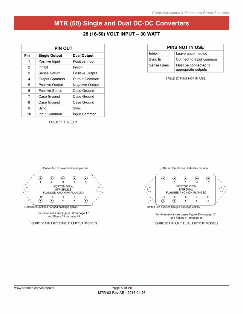
BOTTOM VIEWMTR SINGLE
FLANGED AND NON-FLANGED
Dot on top of cover indicates pin one.
Dotted line outlines flanged package option.
610 789
1 2 3 4 5
Figure 5: pin out singLe output MoDeLs
FordimensionsseeFigure30onpage17andFigure31onpage18.
BOTTOM VIEWMTR DUAL
FLANGED AND NON-FLANGED
Dot on top of cover indicates pin one.
610 789
1 2 3 4 5
Dotted line outlines flanged package option.
FordimensionsseecasesFigure30onpage17andFigure31onpage18.
Figure 6: pin out DuaL output MoDeLs
PIN OutPin single Output Dual Output1 PositiveInput PositiveInput2 Inhibit Inhibit3 SenseReturn PositiveOutput4 OutputCommon OutputCommon5 PositiveOutput NegativeOutput6 PositiveSense CaseGround7 CaseGround CaseGround8 CaseGround CaseGround9 Sync Sync10 InputCommon InputCommon
PINs NOt IN useInhibit LeaveunconnectedSyncIn ConnecttoinputcommonSenseLines Mustbeconnectedto
appropriateoutputs
tabLe 1: pin out
tabLe 2: pins not in use
Crane Aerospace & Electronics Power Solutions
Mtr (50) single and Dual DC-DC Converters28 (16-50) VOlt INPut – 30 Watt
www.craneae.com/interpoint Page5of20MTR-02RevAE-2016.04.26

MODel NuMberINg keyMTR 28 12 D F / 883
Base ModelInput Voltage
Output Voltage
Screening
Number of Outputs
Case Option("F" indicates flanged option, non-flanged case has no designator in this position)
(S = single, D = dual)
(Standard screening has no designatorin this position.)
Figure 7: MoDeL nuMbering key
tabLe 3: sMD nuMber Cross reFerenCe
Figure 8: Cover Marking For Mtr (50) - 50 vin
tabLe 4: MoDeL nuMber options
MODel NuMber OPtIONs tO determine the mOdel number enter One OptiOn frOm each categOry in the fOrm belOw.
CategOry base Model and Input Voltage
Output Voltage 1 Number of Outputs 2
Case Options 3 screening 4
OPtIONs MTR28
3R3,05,8R5,12,15 S (non-flanged,leaveblank) (standard,leaveblank)05,12,15 D F(flanged) ES
883
FIll IN FOr MODel # MTR28 /
Notes1.OutputVoltage:AnRindicatesadecimalpoint.3R3is3.3voltsout.Thevaluesof3.3and8.5voltsareonlyavailableinsingleoutputmodels.2.NumberofOutputs:SisasingleoutputandDisadualoutput.3.CaseOptions:Forthestandardcase,Figure30onpage17,leavethecaseoptionblank.Fortheflangedcaseoption,Figure31onpage18,inserttheletterFintheCaseOptionposition.
4.Screening:Forstandardscreeningleavethescreeningoptionblank.Forotherscreeningoptions,insertthedesiredscreeninglevel.FormoreinformationseeTable9onpage19andTable10onpage20.
sMD NuMbersStandard micrOcircuit drawing (Smd)
mtr Similar part
5962-0150103HXC MTR283R3S/8835962-9306803HXC MTR2805S/8835962-9306903HXC MTR2812S/8835962-9307003HXC MTR2815S/8835962-9320503HXC MTR2805D/8835962-9307103HXC MTR2812D/8835962-9307203HXC MTR2815D/883Toindicatetheflangedcaseoptionchangethe“X”to“Z”IntheSMDnumber.TheSMDnumbershownisforClassHscreening,non-flanged.ForexactspecificationsforanSMDproduct,refertotheSMDdrawing.SMDscanbedownloadedfromhttp://www.landandmaritime.dla.mil/programs/smcr
MTR2805S
CAGE 50821
INTERPOINT MTR (50) DC-DC CONVERTER
B
SN DC
CRANE AEROSPACE & ELECTRONICSTWN
Crane Aerospace & Electronics Power Solutions
Mtr (50) single and Dual DC-DC Converters28 (16-50) VOlt INPut – 30 Watt
www.craneae.com/interpoint Page6of20MTR-02RevAE-2016.04.26

tabLe 5: operating ConDitions, aLL MoDeLs: 25°C tC, 28 vin, 100% LoaD, unLess otherwise speCiFieD.
ALLMODELSPARAMETER CONDITIONS MIN TYP MAX UNITSLEADSOLDERINGTEMPERATURE1 10SECONDSMAX. — — 300 °CSTORAGETEMPERATURE1 -65 — +150 °C
CASEOPERATING FULLPOWER -55 — +125 °CTEMPERATURE ABSOLUTE1 -55 — +135
DERATINGOUTPUTPOWER/CURRENT1 LINEARLY From100%at125°Cto0%at135°C
ESDRATING1 MILSTD883METHOD3015 — — >8000 VMIL-PRF-38534,3.9.5.8.2 CLASS3BISOLATION:INPUTTOOUTPUTORANY @500VDCAT25°C 100 — — MegohmsPINTOCASEEXCEPTCASEPINS
INPUTTOOUTPUTCAPACITANCE1 — 50 — pF
CURRENTLIMIT2 %OFFULLLOAD — 140 — %
AUDIOREJECTION1 — 40 — dB
CONVERSIONFREQUENCY,FREERUN -55°CTO+125°C 530 — 670 kHz
SYNCHRONIZATION INPUTFREQUENCY 500 — 675 kHz
-55°CTO+125°C DUTYCYCLE1 40 — 60 %
ACTIVELOW — — 0.8 VACTIVEHIGH1 4.5 — 5.0
REFERENCEDTO INPUTCOMMONIFNOTUSED CONNECTTOINPUTCOMMON
INHIBITACTIVELOW(OUTPUTDISABLED) INHIBITPINPULLEDLOW — — 0.8 V
Donotapplyavoltagetotheinhibitpin.3 INHIBITPINSOURCECURRENT1 — — 8 mA
REFERENCEDTO INPUTCOMMON
INHIBITACTIVEHIGH(OUTPUTENABLED) INHIBITPINCONDITION OPENCOLLECTOROR
Donotapplyavoltagetotheinhibitpin.3 UNCONNECTEDOPENINHIBITPINVOLTAGE1 9 — 11 V
Notes1.Guaranteedbyqualificationtestand/oranalysis.Notanin-linetest.2.Dualoutputs:Theover-currentlimitwilltriggerwhenthesumofthecurrentsfrombothoutputsreaches140%(typicalvalue)ofthemaximumrated“total”currentofbothoutputs.
3.Anexternalinhibitinterfaceshouldbeusedtopulltheinhibitloworleaveitfloating.Theinhibitpincanbeleftunconnectedifnotused.
For mean time between failures (MTBF) contact Applications [email protected] +1 425-882-3100 option 7
Crane Aerospace & Electronics Power Solutions
Mtr (50) single and Dual DC-DC Converters28 (16-50) VOlt INPut – 30 Watt
www.craneae.com/interpoint Page7of20MTR-02RevAE-2016.04.26

tabLe 6: eLeCtriCaL CharaCteristiCs -55°C to +125°C Case, 28 vin, 100% LoaD, Free run, unLess otherwise speCiFieD.
SINGLEOUTPUTMODELS MTR283R3S MTR2805S MTR288R5SUNITSPARAMETER CONDITIONS MIN TYP MAX MIN TYP MAX MIN TYP MAX
OUTPUTVOLTAGE 3.201 3.30 3.399 4.85 5.00 5.15 8.23 8.5 8.77 VOUTPUTCURRENT VIN=16TO50V 0 — 6.06 0 — 5.0 0 — 2.94 AOUTPUTPOWER VIN=16TO50V 0 — 20 0 — 25 0 — 25 WOUTPUTRIPPLE TC=25°C — 10 40 — 15 70 — 15 60 mVp-p10kHZ-2MHZ TC=-55°CTO+125°C — 15 50 — 15 90 — 20 60LINEREGULATION VIN=16 to 50 v — 0 10 — 2 50 — 2 50 mVLOADREGULATION NOLOADTOFULL — 1 10 — 2 50 — 2 50 mVINPUTVOLTAGE CONTINUOUS 16 28 50 16 28 50 16 28 50 VNOLOADTOFULL TRANSIENT50ms1 — — 80 — — 80 — — 80 V
INPUTCURRENT NOLOAD — 40 80 — 50 80 — 50 80 mAINHIBITED — 3 8 — 3 8 — 3 8
INPUTRIPPLECURRENT2 10kHZ-10MHZ — 30 100 — 30 100 — 30 100 mAp-pEFFICIENCY TC=25°C 73 74 — 75 77 — 77 81 — %
TC=-55°CTO+125°C 71 74 — 73 76 — 76 79 —LOADFAULT3 POWERDISSIPATION — 8 12 — 8 12 — 6 12 WSHORTCIRCUIT RECOVERY1 — 1.4 6 — 1.4 5 — 1.4 5 msSTEPLOADRESPONSE4 TRANSIENT — ±80 ±250 — ±100 ±300 — ±150 ±400 mVpk50%-100%-50% RECOVERY — 50 200 — 50 200 — 30 200 µsSTEPLINERESPONSE1,4 TRANSIENT — — ±300 — ±200 ±300 — ±400 ±500 mVpk16-40-16V RECOVERY — — 400 — — 400 — — 400 µsSTART-UP5 DELAY — 2.5 5 — 2.5 5 — 2.5 5 msFULLLOAD OVERSHOOT1 — 0 50 — 0 80 — 0 150 mVpkCAPACITIVELOAD1 NOEFFECTONDC — — 3000 — — 3000 — — 3000 µF
PERFORMANCE
Notes1.Guaranteedbyqualificationtestand/oranalysis.Notanin-linetest.2.Testedwith6800pFceramicbypasscapacitorconnectedexternallyfrominputcommontocase.
3.Indefiniteshortcircuitprotectionnotguaranteedabove125°Ccase.
4.RecoverytimeismeasuredfromapplicationofthetransienttopointatwhichVOUTiswithin1%offinalvalue.
5.Testedonreleasefrominhibit.
Crane Aerospace & Electronics Power Solutions
Mtr (50) single and Dual DC-DC Converters28 (16-50) VOlt INPut – 30 Watt
www.craneae.com/interpoint Page8of20MTR-02RevAE-2016.04.26

Notes1.Guaranteedbyqualificationtestand/oranalysis.Notanin-linetest.2.Testedwith6800pFceramicbypasscapacitorconnectedexternallyfrominputcommontocase.
3.Indefiniteshortcircuitprotectionnotguaranteedabove125°Ccase.
4.RecoverytimeismeasuredfromapplicationofthetransienttopointatwhichVOUTiswithin1%offinalvalue.
5.Testedonreleasefrominhibit.
SINGLEOUTPUTMODELS MTR2812S MTR2815SUNITSPARAMETER CONDITIONS MIN TYP MAX MIN TYP MAX
OUTPUTVOLTAGE 11.64 12.00 12.36 14.55 15.00 15.45 VOUTPUTCURRENT VIN=16TO50V 0 — 2.5 0 — 2.0 AOUTPUTPOWER VIN=16TO50V 0 — 30 0 — 30 WOUTPUTRIPPLE TC=25°C — 10 40 — 10 40 mVp-p
10kHz-2MHz TC=-55°CTO+125°C — 15 90 — 15 90LINEREGULATION VIN=16 to 50 v — 2 50 — 2 50 mVLOADREGULATION NOLOADTOFULL — 2 50 — 2 50 mVINPUTVOLTAGE CONTINUOUS 16 28 50 16 28 50 VNOLOADTOFULL TRANSIENT50ms1 — — 80 — — 80 V
INPUTCURRENT NOLOAD — 50 80 — 50 80 mAINHIBITED — 3 8 — 3 8
INPUTRIPPLECURRENT2 10kHz-10MHz — 35 100 — 35 100 mAp-pEFFICIENCY TC=25°C 77 80 — 79 80 — %
TC=-55°CTO+125°C 75 77 — 75 77 —LOADFAULT3 POWERDISSIPATION — 6 12 — 5 12 WSHORTCIRCUIT RECOVERY1 — 1.4 5 — 1.4 5 msSTEPLOADRESPONSE4 TRANSIENT — ±150 ±400 — ±150 ±500 mVpk50%-100%-50% RECOVERY — 30 200 — 30 200 µsSTEPLINERESPONSE1,4 TRANSIENT — ±400 ±500 — ±500 ±600 mVpk16-40-16V RECOVERY — — 400 — — 400 µsSTART-UP5 DELAY — 2.5 5 — 2.5 5 msFULLLOAD OVERSHOOT1 — 0 180 — 0 180 mVpkCAPACITIVELOAD1 NOEFFECTONDC — — 3000 — — 3000 µF
PERFORMANCE
tabLe 7: eLeCtriCaL CharaCteristiCs -55°C to +125°C Case, 28 vin, 100% LoaD, Free run, unLess otherwise speCiFieD.
Crane Aerospace & Electronics Power Solutions
Mtr (50) single and Dual DC-DC Converters28 (16-50) VOlt INPut – 30 Watt
www.craneae.com/interpoint Page9of20MTR-02RevAE-2016.04.26

Notes1.Guaranteedbyqualificationtestand/oranalysis.Notanin-linetest.2.Upto90%ofthetotaloutputcurrent/powerisavailablefromeitheroutputprovidingtheoppositeoutputiscarryingatleast10%ofthetotaloutputpower.
3.EffectonnegativeVOUTfrom50%/50%loadsto80%/20%or20%/80%loads.4.EffectonnegativeVOUTfrom50%/50%loadsto90%/10%or10%/90%loads.SeeFigure21onpage14.
5.Testedwith6800pFceramicbypasscapacitorconnectedexternallyfrominputcommontocase.
6.Indefiniteshortcircuitprotectionnotguaranteedabove125°Ccase.7.RecoverytimeismeasuredfromapplicationofthetransienttopointatwhichVOUTiswithin1%offinalvalue.
8.Testedonreleasefrominhibit.9.Appliestoeachoutput.
DUALOUTPUTMODELS MTR2805D MTR2812D MTR2815DUNITSPARAMETER CONDITIONS MIN TYP MAX MIN TYP MAX MIN TYP MAX
OUTPUTVOLTAGE +VOUT 4.850 5.00 5.150 11.64 12.00 12.36 14.55 15.00 15.45 V-VOUT 4.825 5.00 5.172 11.58 12.00 12.42 14.47 15.00 15.53
OUTPUTCURRENT2 EITHEROUTPUT 0 2.5 4.51 0 1.25 2.251 0 1.00 1.801 AVIN=16TO50V TOTALOUTPUT — — 5 — — 2.5 — — 2.00
OUTPUTPOWER2 EITHEROUTPUT 0 12.5 22.51 0 15 271 0 15 271 WVIN=16TO50V TOTALOUTPUT — — 25 — — 30 — — 30
OUTPUTRIPPLE TC=25°C — 5 40 — 20 80 — 20 80 mVp-p10kHz-2MHz±VOUT TC=-55°CTO+125°C — 10 90 — 30 120 — 20 120
LINEREGULATION +VOUT — 2 50 — 2 50 — 2 50 mVVIN=16TO50V -VOUT — 5 100 — 20 150 — 40 180
LOADREGULATION +VOUT — 2 50 — 2 50 — 2 50 mVNOLOADTOFULL -VOUT — 10 100 — 20 150 — 20 180
CROSSREGULATION1 SEENOTE3 — 6 10 — 3 6 — 3 6 %EFFECTON-VOUT,25°C SEENOTE4 — 9 14 — 5 9 — 6 9
INPUTVOLTAGE CONTINUOUS 16 28 50 16 28 50 16 28 50 V
NOLOADTOFULL TRANSIENT50ms. 1 — — 80 — — 80 — — 80 V
INPUTCURRENT NOLOAD — 50 90 – 60 90 — 60 90 mAINHIBITED — 3 8 — 3 8 — 3 8
INPUTRIPPLECURRENT5 10kHz-10MHz — 25 100 — 30 100 — 30 100 mAp-pEFFICIENCY TC=25°C 76 79 — 76 80 — 78 80 — %BALANCEDLOAD TC=-55°CTO+125°C 73 78 — 74 77 — 75 77 —
LOADFAULT6 POWERDISSIPATION — 7 12 — 5 12 — 5 12 WSHORTCIRCUIT RECOVERY1 — 1.4 5.0 — 1.4 5.0 — 1.4 5.0 msSTEPLOADRESPONSE7 TRANSIENT — ±80 ±300 — ±130 ±300 — ±120 ±400 mVpk50%-100%-50%±VOUT RECOVERY — 70 200 — 10 200 — 10 200 µsSTEPLINERESPONSE1,7 TRANSIENT — ±200 ±400 — ±200 ±400 — ±400 ±500 mVpk16-40-16V±VOUT RECOVERY — — 400 — — 400 — — 400 µsSTART-UP8 DELAY — 2.5 5 — 2.5 5 — 2.5 5 msFULLLOAD OVERSHOOT1 — 0 180 — 0 180 — 0 180 mVpkCAPACITIVELOAD1,9 NOEFFECTONDC — — 1500 — — 1500 — — 1500 µF
PERFORMANCE
tabLe 8: eLeCtriCaL CharaCteristiCs -55°C to +125°C Case, 28 vin, 100% LoaD, Free run, unLess otherwise speCiFieD.
Crane Aerospace & Electronics Power Solutions
Mtr (50) single and Dual DC-DC Converters28 (16-50) VOlt INPut – 30 Watt
www.craneae.com/interpoint Page10of20MTR-02RevAE-2016.04.26

typiCaL perForManCe pLots: 25°C Case, 28 vin, 100% LoaD, Free run, unLess otherwise speCiFieD.For reFerenCe onLy, not guaranteeD speCiFiCations.
Mtr2805s step LoaD 50% - 100% - 50%Mtr2805s auDio rejeCtion
Mtr2805s step Line 16 - 40 voLts Mtr2805s step Line 40 - 16 voLts
Figure 9 Figure 10
Figure 11 Figure 12
Crane Aerospace & Electronics Power Solutions
Mtr (50) single and Dual DC-DC Converters28 (16-50) VOlt INPut – 30 Watt
www.craneae.com/interpoint Page11of20MTR-02RevAE-2016.04.26

typiCaL perForManCe pLots: 25°C Case, 28 vin, 100% LoaD, Free run, unLess otherwise speCiFieD.For reFerenCe onLy, not guaranteeD speCiFiCations.
Figure 13 Figure 14
Figure 15 Figure 16
Mtr2805s start-up into no LoaD, 3000 µF Cap LoaD Mtr2805s start-up into no LoaD
Mtr283r3s eFFiCienCy
45
55
65
75
85
4 8 12 16 20
WATTS
OUTPUT POWER20% 100%
EFFI
CIE
NC
Y (%
)
28 V
50 V
16 V
42 V
Mtr2805s eFFiCienCy
40
45
50
55
60
65
70
75
80
85
5 10 15 20 25WATTS
OUTPUT POWER
20% 100%
EFFI
CIE
NC
Y (%
)
28 V
50 V
16 V
42 V
Crane Aerospace & Electronics Power Solutions
Mtr (50) single and Dual DC-DC Converters28 (16-50) VOlt INPut – 30 Watt
www.craneae.com/interpoint Page12of20MTR-02RevAE-2016.04.26

typiCaL perForManCe pLots: 25°C Case, 28 vin, 100% LoaD, Free run, unLess otherwise speCiFieD.For reFerenCe onLy, not guaranteeD speCiFiCations.
Figure 17
Mtr2812s eFFiCienCy
Figure 18
Figure 19 Mtr2815s eFFiCienCy
50
60
70
80
90
5 10 15 20 25 30
WATTS
OUTPUT POWER
20% 100%
EFFI
CIE
NC
Y (%
)
28 V
50 V
16 V
42 V
70
75
80
85
90
5 10 15 20 25
WATTS
OUTPUT POWER
20% 100%
EFFI
CIE
NC
Y (%
)
28 V 50 V
16 V 42 V
Mtr288r5s eFFiCienCy
50
60
70
80
90
5 10 15 20 25
WATTS
OUTPUT POWER
20% 100%
EFFI
CIE
NC
Y (%
)
28 V
50 V
16 V
42 V
Crane Aerospace & Electronics Power Solutions
Mtr (50) single and Dual DC-DC Converters28 (16-50) VOlt INPut – 30 Watt
www.craneae.com/interpoint Page13of20MTR-02RevAE-2016.04.26

typiCaL perForManCe pLots: 25°C Case, 28 vin, 100% LoaD, Free run, unLess otherwise speCiFieD.For reFerenCe onLy, not guaranteeD speCiFiCations.
-10
-8
-6
-4
-2
0
2
4
6
8
10
10/90 30/70 50/50 70/30 90/10
MTR2805D
MTR2812D
MTR2815D
-Vou
t Vo
ltage
Cha
nge
(%)
Output Load (+Vout/-Vout %)
Figure 20 Figure 21
Figure 22 Figure 23
Mtr2815D auDio rejeCtion Mtr Cross reguLation
Mtr2815D step LoaD 50% - 100% - 50% Mtr2815D step Line 16 - 40 voLts
Crane Aerospace & Electronics Power Solutions
Mtr (50) single and Dual DC-DC Converters28 (16-50) VOlt INPut – 30 Watt
www.craneae.com/interpoint Page14of20MTR-02RevAE-2016.04.26

typiCaL perForManCe pLots: 25°C Case, 28 vin, 100% LoaD, Free run, unLess otherwise speCiFieD.For reFerenCe onLy, not guaranteeD speCiFiCations.
Figure 24 Figure 25
Figure 26 Figure 27
Mtr2815D start-up into no LoaD, 1500 µF Cap LoaD eaCh
Mtr2815D start-up into no LoaD Mtr2805D eFFiCienCy
50
55
60
65
70
75
80
85
5 10 15 20 25
WATTS
OUTPUT POWER
20% 100%
EFFI
CIE
NC
Y (%
)
28 V
50 V
16 V
42 V
Mtr2815D step Line 40 - 16 voLts
Crane Aerospace & Electronics Power Solutions
Mtr (50) single and Dual DC-DC Converters28 (16-50) VOlt INPut – 30 Watt
www.craneae.com/interpoint Page15of20MTR-02RevAE-2016.04.26

typiCaL perForManCe pLots: 25°C Case, 28 vin, 100% LoaD, Free run, unLess otherwise speCiFieD.For reFerenCe onLy, not guaranteeD speCiFiCations.
65
70
75
80
85
90
5 10 15 20 25
WATTS
OUTPUT POWER
20% 100%
EFFI
CIE
NC
Y (%
)
28 V 50 V
16 V
42 V
Figure 28 Figure 29
Mtr2815D eFFiCienCyMtr2812D eFFiCienCy
50
55
60
65
70
75
80
85
5 10 15 20 25 30
WATTS
OUTPUT POWER
20% 100%
EFFI
CIE
NC
Y (%
)
28 V
50 V
16 V
42 V
Crane Aerospace & Electronics Power Solutions
Mtr (50) single and Dual DC-DC Converters28 (16-50) VOlt INPut – 30 Watt
www.craneae.com/interpoint Page16of20MTR-02RevAE-2016.04.26

0.155 (3.94)
0.955 (24.26)
0.155 (3.94)
0.955 (24.26)
610 789
Seam Seal
0.00
0
0.040 dia(1.02)
0.000
0.00
0
0.40
0 m
ax.
(10.
16)
0.25
(6.4
)
0.24
5 (6
.22)
1.84
5 (4
6.86
)
2.10
0 m
ax. (
53.3
4)
1 2
610
BOTTOM VIEW MTR SINGLE AND DUAL
3 4 5
789
0.00
0
0.000
0.24
5 (6
.22)
1.84
5 (4
6.86
)
2.10
0 m
ax. (
53.3
4)
1.115 max. (28.32)
1 2 3 4 5
0.64
5 (1
6.38
)
1.04
5 (2
6.54
)
1.44
5 (3
6.70
)
0.64
5 (1
6.38
)
1.04
5 (2
6.54
)
1.44
5 (3
6.70
)
Squared corner and dot on topof case indicate pin one.
Squared corner and dot on topof case indicate pin one.
Weight: 50 grams maximum
Case dimensions in inches (mm)Tolerance ±0.005 (0.13) for three decimal places ±0.01 (0.3) for two decimal places unless otherwise specified
CAUTIONHeat from reflow or wave soldering may damage the device. Solder pins individually with heat application not exceeding 300°C for 10 seconds per pin.
MaterialsHeader Cold Rolled Steel/Nickel/GoldCover Kovar/NickelPins #52 alloy/Gold ceramic seal Gold plating of 50 - 150 microinches included in pin diameter Seal hole 0.120 ±0.002 (3.05 ± 0.05)
Case H2 MTR SD, Rev L, 2015.04.21Please refer to the numerical dimensions for accuracy..
1.115 max. (28.32)
DUAL
SINGLE
Figure 30: Case h2
Crane Aerospace & Electronics Power Solutions
Mtr (50) single and Dual DC-DC Converters28 (16-50) VOlt INPut – 30 Watt
www.craneae.com/interpoint Page17of20MTR-02RevAE-2016.04.26

Figure 31: Case k3
610 789
0.040 dia(1.02)
0.00
0
0.40
0 m
ax.
(10.
16)
0.25
(6.4
)
0.155 (3.94)
0.955 (24.26)
Seam Seal
0.24
5(6
.22)
– 0.
230
(5.8
4)
1.84
5(4
6.86
)
2.32
0(5
8.93
)
0.2
30(5
.84)
2.32
0(5
8.93
)
1 2
610
Flanged cases: Designator “F” required in Case Option position of model number.BOTTOM VIEW MTR SINGLE AND DUAL FLANGED
3 4 5
789
(0.0
00)
0.24
5(6
.22)
1.84
5(4
6.86
)(2
.090
(53.
09))
(0.0
00)
(2.0
90(5
3.09
))
1 2 3 4 5
0.64
5(1
6.38
)
1.04
5(2
6.54
)
1.44
5(3
6.70
)
0.64
5(1
6.38
)
1.04
5(2
6.54
)
1.44
5(3
6.70
)
0.000
1.115 max. (28.32)
0.555 (14.1)
Dot on top of case indicates pin one
Dot on top of case indicates pin one
SINGLE
DUAL
Weight: 52 grams maximum
Case dimensions in inches (mm)Tolerance ±0.005 (0.13) for three decimal places ±0.01 (0.3) for two decimal places unless otherwise specified
CAUTIONHeat from reflow or wave soldering may damage the device. Solder pins individually with heat application not exceeding 300°C for 10 seconds per pin.
MaterialsHeader Cold Rolled Steel/Nickel/GoldCover Kovar/NickelPins #52 alloy/Gold, ceramic seal Gold plating of 50 - 150 microinches included in pin diameter Seal hole 0.120 ±0.002 (3.04 ±0.05)
Case K3 MTR SD F, Rev M, 2015.04.21Please refer to the numerical dimensions for accuracy.
2 x R 0.170 (4.32)
2 x Dia 0.162 ±0.002 (4.11 ±0.05)
2 x R 0.170 (4.32)
2 x Dia 0.162 ±0.002 (4.11 ±0.05)
(2.910 max (73.91))
Flange thickness: 0.060 (1.52)
Base Plate Detail, Edge View
top of header
Crane Aerospace & Electronics Power Solutions
Mtr (50) single and Dual DC-DC Converters28 (16-50) VOlt INPut – 30 Watt
www.craneae.com/interpoint Page18of20MTR-02RevAE-2016.04.26

tabLe 9: eLeMent evaLuation
Crane Aerospace & Electronics Power Solutions
Mtr (50) single and Dual DC-DC Converters28 (16-50) VOlt INPut – 30 Watt
www.craneae.com/interpoint Page19of20MTR-02RevAE-2016.04.26
Tableisforreferenceonly.SeeindividualSeries'datasheetsforspecificscreening.
tabLe 8: eLeMent evaLuation high reLiabiLity DC-DC Converters anD eMi FiLters /883 (CLass h)
element eValuatiOn 1 high reliability /883 (claSS h)
Qml
claSS h /883
cOmpOnent-leVel teSt perfOrmed m/S 2 p 3
ElementElectrical n n
Visual n n
InternalVisual n
FinalElectrical n n
WireBondEvaluation n n
Notes1.Elementevaluationdoesnotapplytostandardand/ESproduct.2.M/S=Activecomponents(microcircuitandsemiconductordie).3.P=Passivecomponents,ClassHelementevaluation.Notapplicabletostandardand/ESelementevaluation.
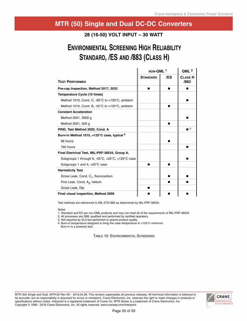
tabLe 10: environMentaL sCreening
Crane Aerospace & Electronics Power Solutions
Mtr (50) single and Dual DC-DC Converters
MTR(50)SingleandDual,MTR-02RevAE-2016.04.26.Thisrevisionsupersedesallpreviousreleases.Alltechnicalinformationisbelievedtobeaccurate,butnoresponsibilityisassumedforerrorsoromissions.CraneElectronics,Inc.reservestherighttomakechangesinproductsorspecificationswithoutnotice.InterpointisaregisteredtrademarkofCraneCo.MTRSeriesisatrademarkofCraneElectronics,Inc.Copyright©1999-2016CraneElectronics,Inc.Allrightsreserved.www.craneae.com/interpoint
Page20of20
28 (16-50) VOlt INPut – 30 WattTableisforreferenceonly.SeeindividualSeries'datasheetsforspecificscreening.
tabLe 9: environMentaL sCreening high reLiabiLity DC-DC Converters anD eMi FiLters stanDarD, /es anD /883 (CLass h)
enVirOnmental Screening high reliability Standard, /eS and /883 (claSS h)
nOn-Qml 1 Qml 2
teSt perfOrmedStandard /eS claSS h
/883
Pre-cap Inspection, Method 2017, 2032 n n n
temperature Cycle (10 times)
Method1010,Cond.C,-65°Cto+150°C,ambient n
Method1010,Cond.B,-55°Cto+125°C,ambient n
Constant accelerationMethod2001,3000g n
Method2001,500g n
PIND, test Method 2020, Cond. a n3
burn-in Method 1015, +125°C case, typical 4
96hours n
160hours n
Final electrical test, MIl-PrF-38534, group a, Subgroups1through6,-55°C,+25°C,+125°Ccase n
Subgroups1and4,+25°Ccase n n
Hermeticity testGrossLeak,Cond.C1,fluorocarbon n n
FineLeak,Cond.A2,helium n n
GrossLeak,Dip n
Final visual inspection, Method 2009 n n n
TestmethodsarereferencedtoMIL-STD-883asdeterminedbyMIL-PRF-38534.
Notes1.StandardandESarenon-QMLproductsandmaynotmeetalloftherequirementsofMIL-PRF-38534.2.AllprocessesareQMLqualifiedandperformedbycertifiedoperators.3.NotrequiredbyDLAbutperformedtoassureproductquality.4.Burn-intemperaturedesignedtobringthecasetemperatureto+125°Cminimum.Burn-inisapoweredtest.