MTB Wheel Set - Manuals & Technical Documentssi.shimano.com/pdfs/dm/DM-WH0005-03-ENG.pdf7...
27
(English) DM-WH0005-03 Dealer's Manual MTB Wheel Set Non-Series WH-MT68 WH-MT66 WH-MT35 WH-MT15 WH-MT500
-
Upload
truongkien -
Category
Documents
-
view
219 -
download
2
Transcript of MTB Wheel Set - Manuals & Technical Documentssi.shimano.com/pdfs/dm/DM-WH0005-03-ENG.pdf7...
(English) DM-WH0005-03
Dealer's Manual
MTB Wheel Set Non-Series
WH-MT68WH-MT66WH-MT35WH-MT15WH-MT500
2
CONTENTS
IMPORTANT NOTICE .............................................................................................. 3
TO ENSURE SAFETY ............................................................................................... 4
INSTALLATION ....................................................................................................... 7Tire size ................................................................................................................................7
List of tools to be used .......................................................................................................8
Installing a cassette sprocket..............................................................................................8
MAINTENANCE ...................................................................................................... 9Spoke lacing ........................................................................................................................9
Replacing the spoke..........................................................................................................11
Disassembly and Assembly < Thru axle type > ................................................................12
Disassembly and Assembly < Quick release type > .........................................................16
Replacement of the freewheel body < Quick release type > .........................................18
Replacement of the freewheel body < Thru axle type > ................................................19
Replacing the covering tape and the rim hole cap ........................................................20
Replacing tubeless tape ....................................................................................................22
How to use a sealant (In the case of type-A) ..................................................................24
Installing and removing tubeless tires .............................................................................25
3
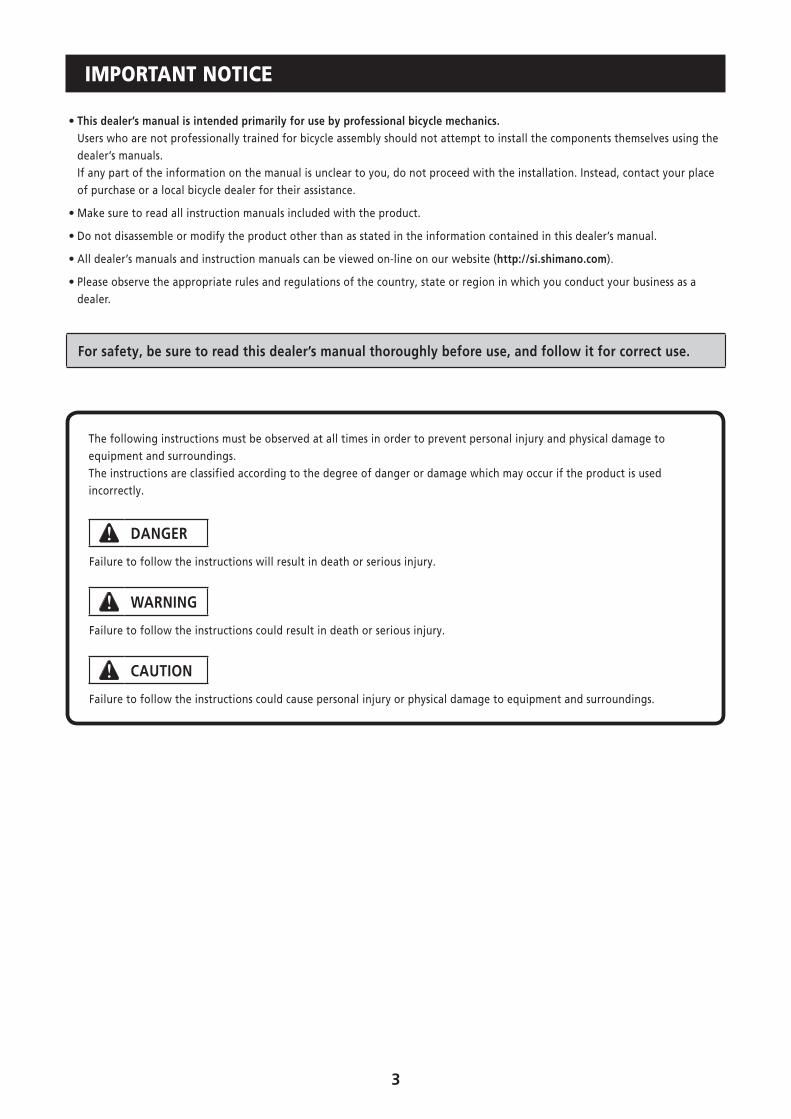
IMPORTANT NOTICE
• This dealer’s manual is intended primarily for use by professional bicycle mechanics.Users who are not professionally trained for bicycle assembly should not attempt to install the components themselves using the dealer’s manuals.If any part of the information on the manual is unclear to you, do not proceed with the installation. Instead, contact your place of purchase or a local bicycle dealer for their assistance.
• Make sure to read all instruction manuals included with the product.
• Do not disassemble or modify the product other than as stated in the information contained in this dealer’s manual.
• All dealer’s manuals and instruction manuals can be viewed on-line on our website (http://si.shimano.com).
• Please observe the appropriate rules and regulations of the country, state or region in which you conduct your business as a dealer.
For safety, be sure to read this dealer’s manual thoroughly before use, and follow it for correct use.
The following instructions must be observed at all times in order to prevent personal injury and physical damage to equipment and surroundings.The instructions are classified according to the degree of danger or damage which may occur if the product is used incorrectly.
DANGER
Failure to follow the instructions will result in death or serious injury.
WARNING
Failure to follow the instructions could result in death or serious injury.
CAUTION
Failure to follow the instructions could cause personal injury or physical damage to equipment and surroundings.
4
TO ENSURE SAFETY
WARNING
• When installing components, be sure to follow the instructions that are given in the instruction manuals.It is recommended that you use only genuine Shimano parts. If parts such as bolts and nuts become loose or damaged, the bicycle may suddenly fall over, which may cause serious injury. In addition, if adjustments are not carried out correctly, problems may occur, and the bicycle may suddenly fall over, which may cause serious injury.
• Be sure to wear safety glasses or goggles to protect your eyes while performing maintenance tasks such as replacing parts.
• After reading the dealer's manual thoroughly, keep it in a safe place for later reference.
Be sure to also inform users of the following:
• Check that the wheels are fastened securely before riding the bicycle. If the wheels are loose in any way, they may come off the bicycle and serious injury may result.
• This wheel is not designed for downhill bicycle riding and freeriding. Hence, do not use it for downhill riding, otherwise the wheel may become bent or otherwise damaged, and accidents may occur as a result.
• If the quick release mechanism is not used correctly, the wheel may come off the bicycle and serious injury could result. Read the Service Instructions for the quick release mechanism thoroughly before use.
• Before use, check the wheels to make sure that there are no bent or loose spokes, dents, scratches or cracks on the rim surface. Do not use the wheel if any of these problems are found. The wheel may break, and you may fall.
< F15 (Front 15 mm Axle), R12 (Rear 12 mm Axle) Wheel (Thru Axle) > • This wheel is not designed for downhill bicycle riding and freeriding. Hence, depending on the riding conditions, the hub axle could develop cracks which may result in failure of the hub axle. This can lead to an accident that could result in serious injury or even death. Before riding, you should carefully check your hubs to make sure that there are no cracks in the axles, and if you find any sign of a crack or any other unusual condition, DO NOT use the bicycle.
• This wheel can be used in combination with the special front fork/frame and the fixed axle only. If it is used in combination with any other front fork/frame or fixed axle, it may cause the wheel to become detached from the bicycle while you are riding and result in serious bodily injury.
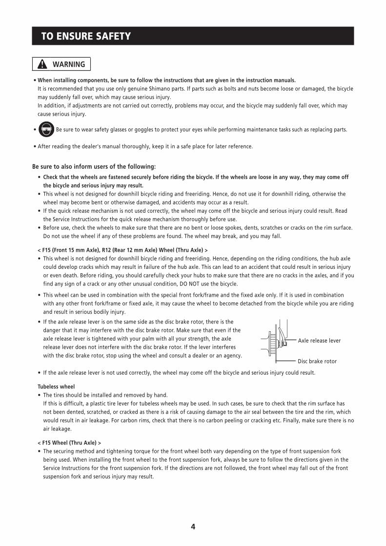
• If the axle release lever is on the same side as the disc brake rotor, there is the danger that it may interfere with the disc brake rotor. Make sure that even if the axle release lever is tightened with your palm with all your strength, the axle release lever does not interfere with the disc brake rotor. If the lever interferes with the disc brake rotor, stop using the wheel and consult a dealer or an agency.
Axle release lever
Disc brake rotor
• If the axle release lever is not used correctly, the wheel may come off the bicycle and serious injury could result.
Tubeless wheel • The tires should be installed and removed by hand. If this is difficult, a plastic tire lever for tubeless wheels may be used. In such cases, be sure to check that the rim surface has not been dented, scratched, or cracked as there is a risk of causing damage to the air seal between the tire and the rim, which would result in air leakage. For carbon rims, check that there is no carbon peeling or cracking etc. Finally, make sure there is no air leakage.
< F15 Wheel (Thru Axle) > • The securing method and tightening torque for the front wheel both vary depending on the type of front suspension fork being used. When installing the front wheel to the front suspension fork, always be sure to follow the directions given in the Service Instructions for the front suspension fork. If the directions are not followed, the front wheel may fall out of the front suspension fork and serious injury may result.
5
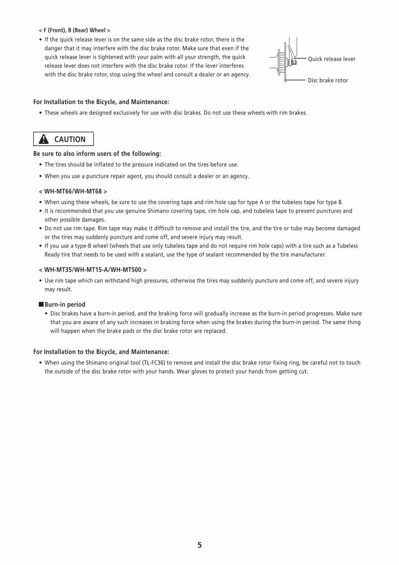
< F (Front), R (Rear) Wheel >
• If the quick release lever is on the same side as the disc brake rotor, there is the danger that it may interfere with the disc brake rotor. Make sure that even if the quick release lever is tightened with your palm with all your strength, the quick release lever does not interfere with the disc brake rotor. If the lever interferes with the disc brake rotor, stop using the wheel and consult a dealer or an agency.
Quick release lever
Disc brake rotor
For Installation to the Bicycle, and Maintenance:
• These wheels are designed exclusively for use with disc brakes. Do not use these wheels with rim brakes.
CAUTION
Be sure to also inform users of the following:
• The tires should be inflated to the pressure indicated on the tires before use.
• When you use a puncture repair agent, you should consult a dealer or an agency.
< WH-MT66/WH-MT68 >
• When using these wheels, be sure to use the covering tape and rim hole cap for type A or the tubeless tape for type B. • It is recommended that you use genuine Shimano covering tape, rim hole cap, and tubeless tape to prevent punctures and other possible damages.
• Do not use rim tape. Rim tape may make it difficult to remove and install the tire, and the tire or tube may become damaged or the tires may suddenly puncture and come off, and severe injury may result.
• If you use a type-B wheel (wheels that use only tubeless tape and do not require rim hole caps) with a tire such as a Tubeless Ready tire that needs to be used with a sealant, use the type of sealant recommended by the tire manufacturer.
< WH-MT35/WH-MT15-A/WH-MT500 >
• Use rim tape which can withstand high pressures, otherwise the tires may suddenly puncture and come off, and severe injury may result.
�Burn-in period • Disc brakes have a burn-in period, and the braking force will gradually increase as the burn-in period progresses. Make sure that you are aware of any such increases in braking force when using the brakes during the burn-in period. The same thing will happen when the brake pads or the disc brake rotor are replaced.
For Installation to the Bicycle, and Maintenance:
• When using the Shimano original tool (TL-FC36) to remove and install the disc brake rotor fixing ring, be careful not to touch the outside of the disc brake rotor with your hands. Wear gloves to protect your hands from getting cut.
6
NOTE
Be sure to also inform users of the following:
• Special nipple wrenches are available as optional accessories.
• Do not apply any oil to the inside of the hub, otherwise the grease will come out.
• We recommend that you ask bicycle dealers to adjust the spoke tensions if there is any initial play in the spokes and after the first 1,000 km of riding.
• Do not use detergent or other chemicals when wiping the wheel, otherwise it may cause the sticker on the rim to peel off.
• We do not recommend that you use general-purpose alkaline puncture repair agents, as they may cause the rims to corrode and allow air leaks to occur.
• Products are not guaranteed against natural wear and deterioration from normal use and aging.
• For maximum performance we highly recommend Shimano lubricants and maintenance products.
For Installation to the Bicycle, and Maintenance:
• Use of genuine Shimano spokes and nipples is strongly recommended. If non-Shimano parts are used, the area where the spokes fit into the hub unit may become damaged.
• If the wheel becomes stiff and difficult to turn, you should lubricate it with grease.
• For compatible reflectors and spoke protectors, check the specifications table (http://si.shimano.com).
The actual product may differ from the illustration because this manual is intended chiefly to explain the procedures for using the product.
7
INSTALLATION
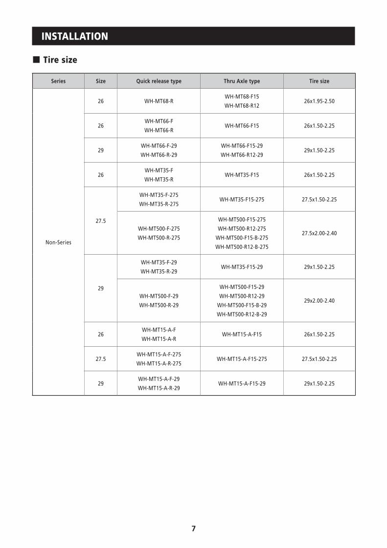
� Tire size
Series Size Quick release type Thru Axle type Tire size
Non-Series
26 WH-MT68-RWH-MT68-F15
WH-MT68-R1226x1.95-2.50
26WH-MT66-F
WH-MT66-RWH-MT66-F15 26x1.50-2.25
29WH-MT66-F-29
WH-MT66-R-29
WH-MT66-F15-29
WH-MT66-R12-2929x1.50-2.25
26WH-MT35-F
WH-MT35-RWH-MT35-F15 26x1.50-2.25
27.5
WH-MT35-F-275
WH-MT35-R-275 WH-MT35-F15-275 27.5x1.50-2.25
WH-MT500-F-275
WH-MT500-R-275
WH-MT500-F15-275
WH-MT500-R12-275
WH-MT500-F15-B-275
WH-MT500-R12-B-275
27.5x2.00-2.40
29
WH-MT35-F-29
WH-MT35-R-29 WH-MT35-F15-29 29x1.50-2.25
WH-MT500-F-29
WH-MT500-R-29
WH-MT500-F15-29
WH-MT500-R12-29
WH-MT500-F15-B-29
WH-MT500-R12-B-29
29x2.00-2.40
26WH-MT15-A-F
WH-MT15-A-R WH-MT15-A-F15 26x1.50-2.25
27.5WH-MT15-A-F-275
WH-MT15-A-R-275WH-MT15-A-F15-275 27.5x1.50-2.25
29WH-MT15-A-F-29
WH-MT15-A-R-29 WH-MT15-A-F15-29 29x1.50-2.25
8
� List of tools to be usedThe following tools are needed to assemble this product.
Usage location Tool
Cassette sprocket TL-LR10/15, TL-SR21, adjustable wrench
Hub
13 mm hub spanner, 15 mm hub spanner, 17 mm
hub spanner, 22 mm hub spanner, 23 mm hub
spanner,
TL-7S20, TL-FH15, TL-WR37
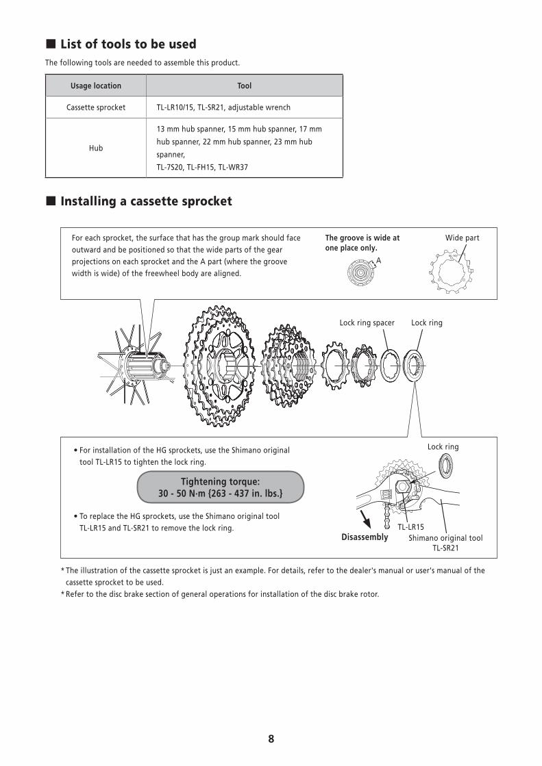
� Installing a cassette sprocket
For each sprocket, the surface that has the group mark should face outward and be positioned so that the wide parts of the gear projections on each sprocket and the A part (where the groove width is wide) of the freewheel body are aligned.
A
The groove is wide at one place only.
Wide part
• For installation of the HG sprockets, use the Shimano original tool TL-LR15 to tighten the lock ring.
Tightening torque:30 - 50 N·m {263 - 437 in. lbs.}
• To replace the HG sprockets, use the Shimano original tool TL-LR15 and TL-SR21 to remove the lock ring.
Shimano original tool TL-SR21
Lock ring
TL-LR15Disassembly
Lock ringLock ring spacer
* The illustration of the cassette sprocket is just an example. For details, refer to the dealer's manual or user's manual of the cassette sprocket to be used.
* Refer to the disc brake section of general operations for installation of the disc brake rotor.
9
MAINTENANCE
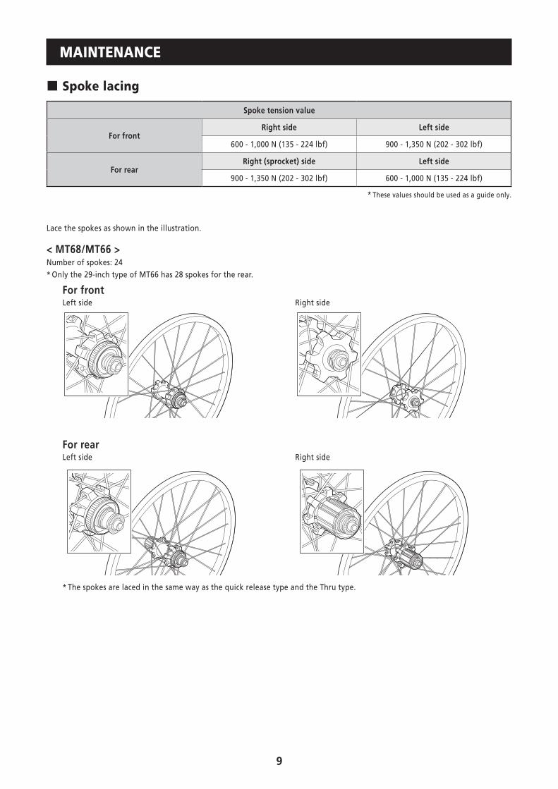
� Spoke lacing
Spoke tension value
For frontRight side Left side
600 - 1,000 N (135 - 224 lbf) 900 - 1,350 N (202 - 302 lbf)
For rearRight (sprocket) side Left side
900 - 1,350 N (202 - 302 lbf) 600 - 1,000 N (135 - 224 lbf)
* These values should be used as a guide only.
Lace the spokes as shown in the illustration.
< MT68/MT66 >Number of spokes: 24* Only the 29-inch type of MT66 has 28 spokes for the rear.
For frontLeft side Right side
For rearLeft side Right side
* The spokes are laced in the same way as the quick release type and the Thru type.
10
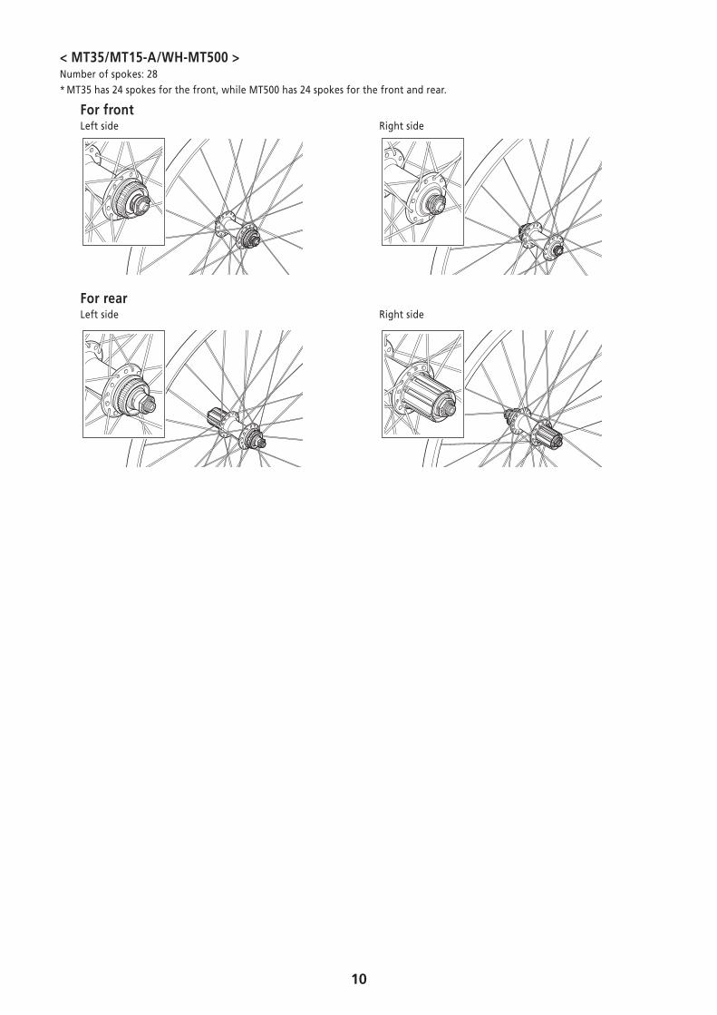
< MT35/MT15-A/WH-MT500 >Number of spokes: 28* MT35 has 24 spokes for the front, while MT500 has 24 spokes for the front and rear.
For frontLeft side Right side
For rearLeft side Right side
11
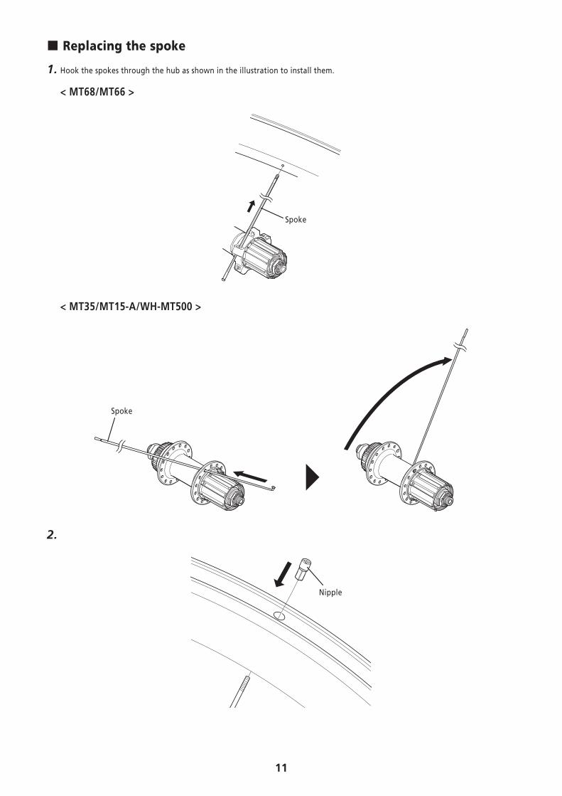
� Replacing the spoke
1. Hook the spokes through the hub as shown in the illustration to install them.
< MT68/MT66 >
Spoke
< MT35/MT15-A/WH-MT500 >
Spoke
2.
Nipple
12
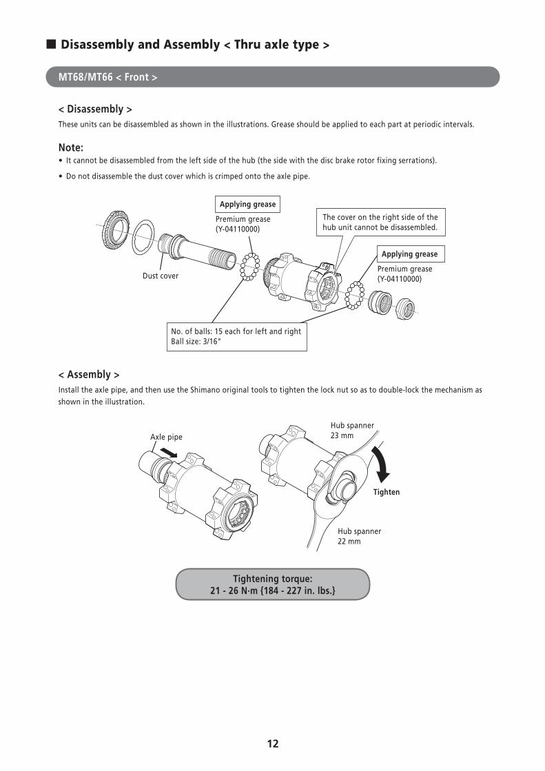
� Disassembly and Assembly < Thru axle type >
MT68/MT66 < Front >
< Disassembly >These units can be disassembled as shown in the illustrations. Grease should be applied to each part at periodic intervals.
Note: • It cannot be disassembled from the left side of the hub (the side with the disc brake rotor fixing serrations).
• Do not disassemble the dust cover which is crimped onto the axle pipe.
The cover on the right side of the hub unit cannot be disassembled.
Premium grease (Y-04110000)
Applying grease
Premium grease (Y-04110000)
Applying grease
No. of balls: 15 each for left and right Ball size: 3/16"
Dust cover
< Assembly >Install the axle pipe, and then use the Shimano original tools to tighten the lock nut so as to double-lock the mechanism as shown in the illustration.
Hub spanner23 mm
Hub spanner22 mm
Tighten
Axle pipe
Tightening torque:21 - 26 N·m {184 - 227 in. lbs.}
13
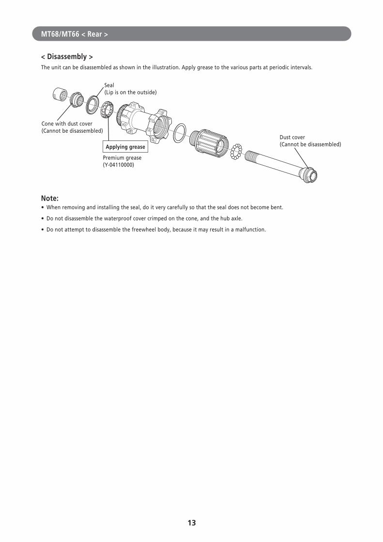
MT68/MT66 < Rear >
< Disassembly >The unit can be disassembled as shown in the illustration. Apply grease to the various parts at periodic intervals.
Seal (Lip is on the outside)
Cone with dust cover (Cannot be disassembled)
Premium grease (Y-04110000)
Applying grease
Dust cover (Cannot be disassembled)
Note: • When removing and installing the seal, do it very carefully so that the seal does not become bent.
• Do not disassemble the waterproof cover crimped on the cone, and the hub axle.
• Do not attempt to disassemble the freewheel body, because it may result in a malfunction.
14
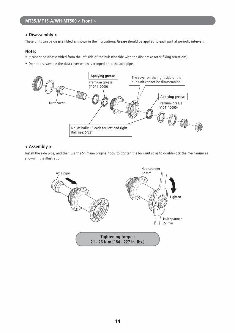
MT35/MT15-A/WH-MT500 < Front >
< Disassembly >These units can be disassembled as shown in the illustrations. Grease should be applied to each part at periodic intervals.
Note: • It cannot be disassembled from the left side of the hub (the side with the disc brake rotor fixing serrations).
• Do not disassemble the dust cover which is crimped onto the axle pipe.
The cover on the right side of the hub unit cannot be disassembled.Premium grease
(Y-04110000)
Applying grease
Premium grease (Y-04110000)
Applying grease
No. of balls: 16 each for left and right Ball size: 5/32"
Dust cover
< Assembly >Install the axle pipe, and then use the Shimano original tools to tighten the lock nut so as to double-lock the mechanism as shown in the illustration.
Tightening torque:21 - 26 N·m {184 - 227 in. lbs.}
Hub spanner22 mm
Hub spanner22 mm
Tighten
Axle pipe
15
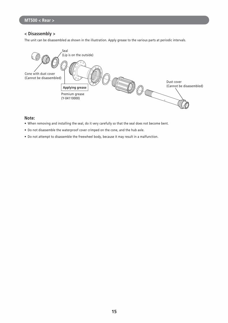
MT500 < Rear >
< Disassembly >The unit can be disassembled as shown in the illustration. Apply grease to the various parts at periodic intervals.
Seal (Lip is on the outside)
Cone with dust cover (Cannot be disassembled)
Premium grease (Y-04110000)
Applying grease
Dust cover (Cannot be disassembled)
Note: • When removing and installing the seal, do it very carefully so that the seal does not become bent.
• Do not disassemble the waterproof cover crimped on the cone, and the hub axle.
• Do not attempt to disassemble the freewheel body, because it may result in a malfunction.
16
� Disassembly and Assembly < Quick release type >
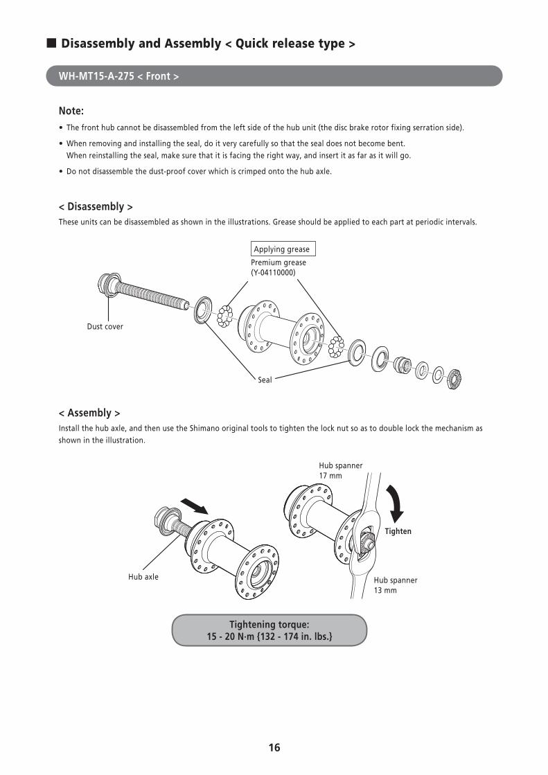
WH-MT15-A-275 < Front >
Note: • The front hub cannot be disassembled from the left side of the hub unit (the disc brake rotor fixing serration side).
• When removing and installing the seal, do it very carefully so that the seal does not become bent. When reinstalling the seal, make sure that it is facing the right way, and insert it as far as it will go.
• Do not disassemble the dust-proof cover which is crimped onto the hub axle.
< Disassembly >These units can be disassembled as shown in the illustrations. Grease should be applied to each part at periodic intervals.
Applying grease
Premium grease(Y-04110000)
Seal
Dust cover
< Assembly >Install the hub axle, and then use the Shimano original tools to tighten the lock nut so as to double lock the mechanism as shown in the illustration.
Tightening torque: 15 - 20 N·m {132 - 174 in. lbs.}
Hub axle
Hub spanner 17 mm
Hub spanner 13 mm
Tighten
17
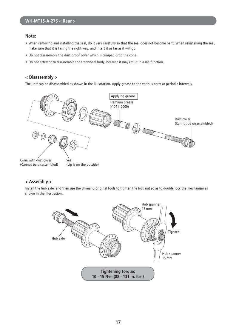
WH-MT15-A-275 < Rear >
Note: • When removing and installing the seal, do it very carefully so that the seal does not become bent. When reinstalling the seal, make sure that it is facing the right way, and insert it as far as it will go.
• Do not disassemble the dust-proof cover which is crimped onto the cone.
• Do not attempt to disassemble the freewheel body, because it may result in a malfunction.
< Disassembly >The unit can be disassembled as shown in the illustration. Apply grease to the various parts at periodic intervals.
Cone with dust cover(Cannot be disassembled)
Applying grease
Premium grease(Y-04110000)
Seal (Lip is on the outside)
Dust cover (Cannot be disassembled)
< Assembly >Install the hub axle, and then use the Shimano original tools to tighten the lock nut so as to double lock the mechanism as shown in the illustration.
Tightening torque: 10 - 15 N·m {88 - 131 in. lbs.}
Hub axle
Tighten
Hub spanner17 mm
Hub spanner15 mm
18
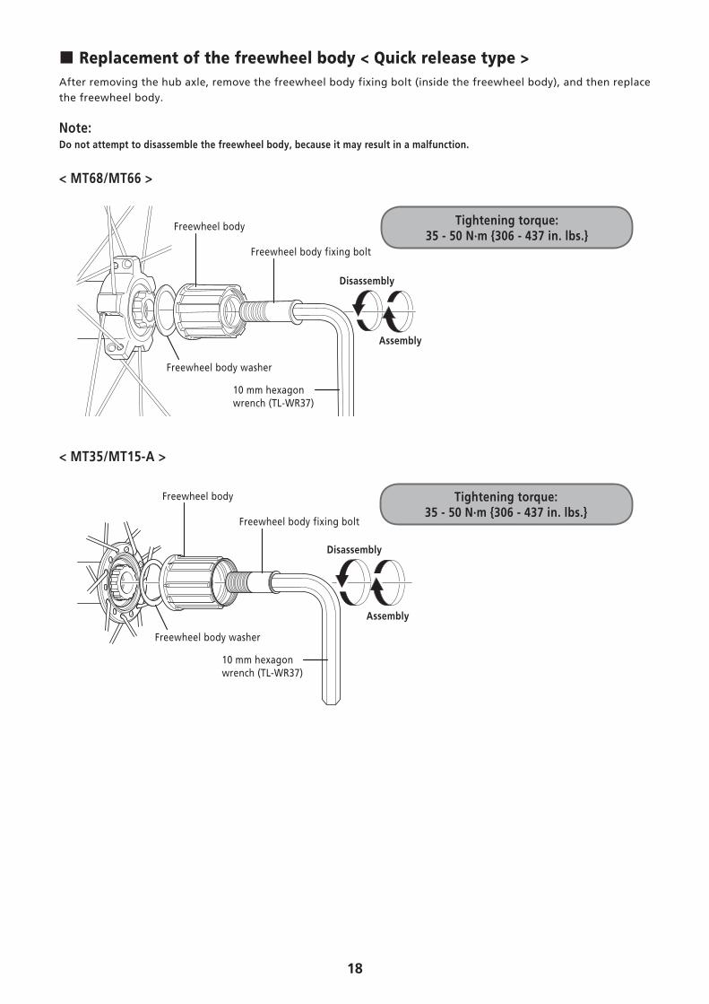
� Replacement of the freewheel body < Quick release type >After removing the hub axle, remove the freewheel body fixing bolt (inside the freewheel body), and then replace the freewheel body.
Note:Do not attempt to disassemble the freewheel body, because it may result in a malfunction.
< MT68/MT66 >
Freewheel body
Freewheel body fixing bolt
Disassembly
Assembly
Freewheel body washer
10 mm hexagon wrench (TL-WR37)
Tightening torque: 35 - 50 N·m {306 - 437 in. lbs.}
< MT35/MT15-A >
Freewheel body
Freewheel body fixing bolt
Disassembly
Assembly
Freewheel body washer
10 mm hexagon wrench (TL-WR37)
Tightening torque: 35 - 50 N·m {306 - 437 in. lbs.}
19
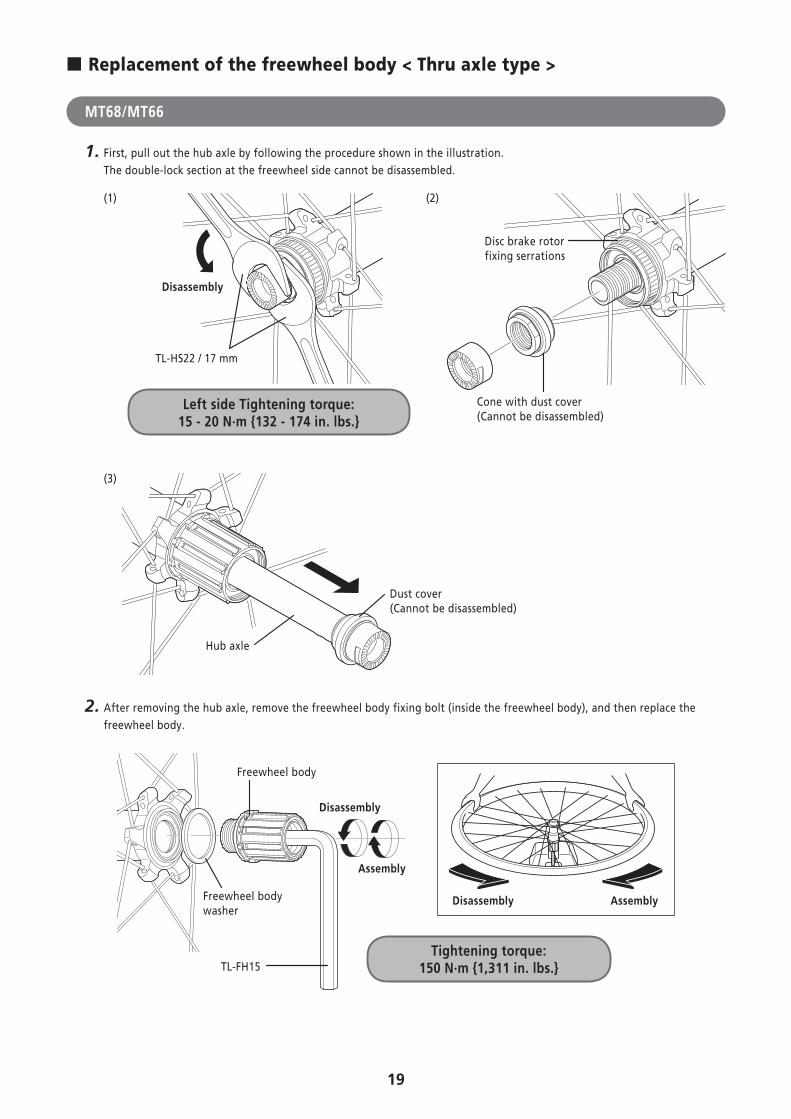
� Replacement of the freewheel body < Thru axle type >
MT68/MT66
1. First, pull out the hub axle by following the procedure shown in the illustration. The double-lock section at the freewheel side cannot be disassembled.
(1)
Left side Tightening torque: 15 - 20 N·m {132 - 174 in. lbs.}
Disassembly
TL-HS22 / 17 mm
(2)
Disc brake rotor fixing serrations
Cone with dust cover (Cannot be disassembled)
(3)
Hub axle
Dust cover (Cannot be disassembled)
2. After removing the hub axle, remove the freewheel body fixing bolt (inside the freewheel body), and then replace the freewheel body.
Tightening torque: 150 N·m {1,311 in. lbs.}
Freewheel body
Freewheel body washer
TL-FH15
Disassembly
Assembly
Disassembly Assembly
20
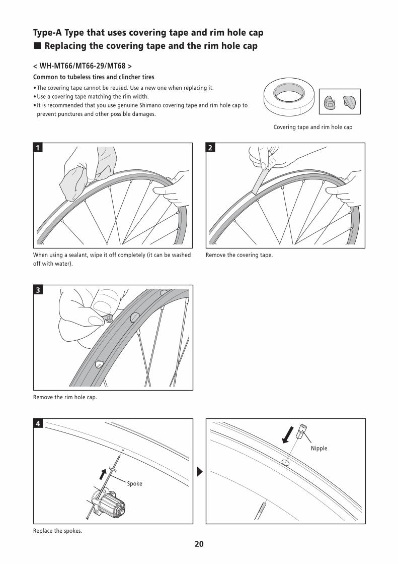
Type-A Type that uses covering tape and rim hole cap � Replacing the covering tape and the rim hole cap
< WH-MT66/MT66-29/MT68 >Common to tubeless tires and clincher tires
• The covering tape cannot be reused. Use a new one when replacing it. • Use a covering tape matching the rim width. • It is recommended that you use genuine Shimano covering tape and rim hole cap to prevent punctures and other possible damages.
Covering tape and rim hole cap
1 2
When using a sealant, wipe it off completely (it can be washed off with water).
Remove the covering tape.
3
Remove the rim hole cap.
4
Spoke
Nipple
Replace the spokes.
21
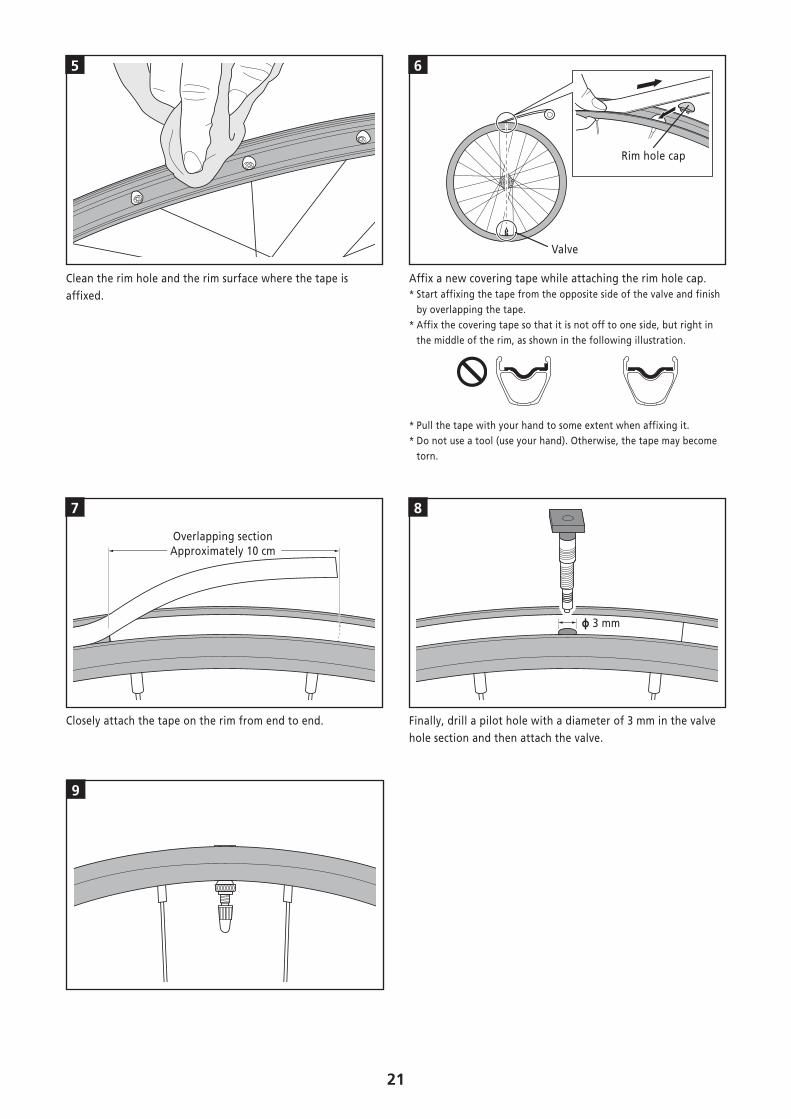
5 6
Rim hole cap
Valve
Clean the rim hole and the rim surface where the tape is affixed.
Affix a new covering tape while attaching the rim hole cap.* Start affixing the tape from the opposite side of the valve and finish
by overlapping the tape.* Affix the covering tape so that it is not off to one side, but right in
the middle of the rim, as shown in the following illustration.
* Pull the tape with your hand to some extent when affixing it.* Do not use a tool (use your hand). Otherwise, the tape may become
torn.
7
Overlapping sectionApproximately 10 cm
8
ɸ 3 mm
Closely attach the tape on the rim from end to end. Finally, drill a pilot hole with a diameter of 3 mm in the valve hole section and then attach the valve.
9
22
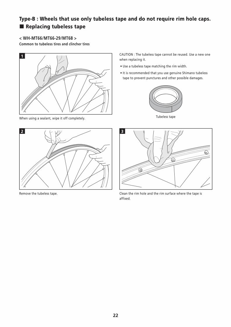
Type-B : Wheels that use only tubeless tape and do not require rim hole caps. � Replacing tubeless tape
< WH-MT66/MT66-29/MT68 >Common to tubeless tires and clincher tires
1 CAUTION : The tubeless tape cannot be reused. Use a new one when replacing it.
• Use a tubeless tape matching the rim width.
• It is recommended that you use genuine Shimano tubeless tape to prevent punctures and other possible damages.
Tubeless tapeWhen using a sealant, wipe it off completely.
2 3
Remove the tubeless tape. Clean the rim hole and the rim surface where the tape is affixed.
23
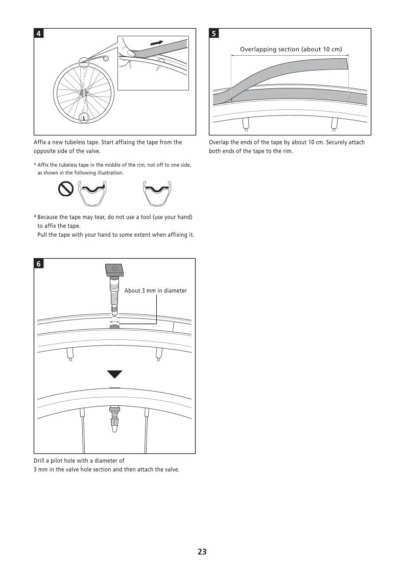
4 5
Overlapping section (about 10 cm)
Affix a new tubeless tape. Start affixing the tape from the opposite side of the valve.
* Affix the tubeless tape in the middle of the rim, not off to one side, as shown in the following illustration.
* Because the tape may tear, do not use a tool (use your hand) to affix the tape. Pull the tape with your hand to some extent when affixing it.
Overlap the ends of the tape by about 10 cm. Securely attach both ends of the tape to the rim.
6
About 3 mm in diameter
Drill a pilot hole with a diameter of 3 mm in the valve hole section and then attach the valve.
24
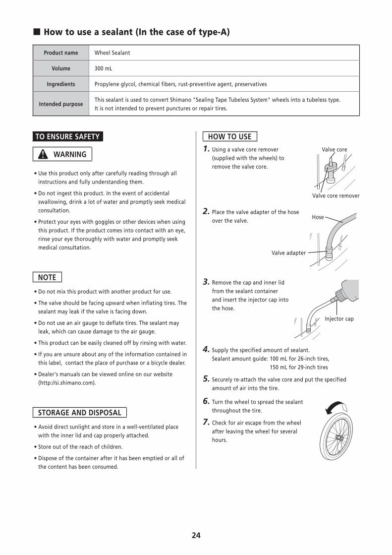
� How to use a sealant (In the case of type-A)
Product name Wheel Sealant
Volume 300 mL
Ingredients Propylene glycol, chemical fibers, rust-preventive agent, preservatives
Intended purposeThis sealant is used to convert Shimano "Sealing Tape Tubeless System" wheels into a tubeless type. It is not intended to prevent punctures or repair tires.
TO ENSURE SAFETY
WARNING
• Use this product only after carefully reading through all instructions and fully understanding them.
• Do not ingest this product. In the event of accidental swallowing, drink a lot of water and promptly seek medical consultation.
• Protect your eyes with goggles or other devices when using this product. If the product comes into contact with an eye, rinse your eye thoroughly with water and promptly seek medical consultation.
NOTE
• Do not mix this product with another product for use.
• The valve should be facing upward when inflating tires. The sealant may leak if the valve is facing down.
• Do not use an air gauge to deflate tires. The sealant may leak, which can cause damage to the air gauge.
• This product can be easily cleaned off by rinsing with water.
• If you are unsure about any of the information contained in this label, contact the place of purchase or a bicycle dealer.
• Dealer's manuals can be viewed online on our website (http://si.shimano.com).
STORAGE AND DISPOSAL
• Avoid direct sunlight and store in a well-ventilated place with the inner lid and cap properly attached.
• Store out of the reach of children.
• Dispose of the container after it has been emptied or all of the content has been consumed.
HOW TO USE
1. Using a valve core remover (supplied with the wheels) to remove the valve core.
Valve core
Valve core remover
2. Place the valve adapter of the hose over the valve.
Hose
Valve adapter
3. Remove the cap and inner lid from the sealant container and insert the injector cap into the hose.
Injector cap
4. Supply the specified amount of sealant. Sealant amount guide: 100 mL for 26-inch tires,
150 mL for 29-inch tires
5. Securely re-attach the valve core and put the specified amount of air into the tire.
6. Turn the wheel to spread the sealant throughout the tire.
7. Check for air escape from the wheel after leaving the wheel for several hours.
25
� Installing and removing tubeless tires
TO ENSURE SAFETY
WARNING
• Read these Technical Service Instructions carefully, and keep them in a safe place for later reference.
CAUTION
• Do not use rim tape if using an inner tube either. Rim tape may make it difficult to remove and install the tire, and the tire or tube may become damaged or the tires may suddenly puncture and come off, and severe injury may result.
CAUTION • The tires should be installed and removed by hand. If this is difficult, a plastic tire lever for tubeless wheels may be used. In such cases, be sure to check that the rim surface has not been dented, scratched, or cracked as there is a risk of causing damage to the air seal between the tire and the rim, which would result in air leakage. For carbon rims, check that there is no carbon peeling or cracking etc. Finally, make sure there is no air leakage. • Do not tighten the valve nut too much, otherwise the valve seal may become warped and air leaks may occur.
Note • If the tires are difficult to fit, use plan water or soapy water to help them slide more easily.
• When you use a type-A wheel, if the tire is difficult to attach or fill with air, apply the sealant on the bead section.
• Products are not guaranteed against natural wear and deterioration from normal use and aging.
Technical Service Instructions
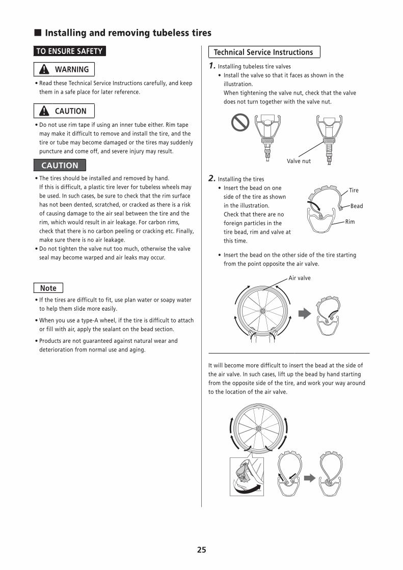
1. Installing tubeless tire valves • Install the valve so that it faces as shown in the illustration. When tightening the valve nut, check that the valve does not turn together with the valve nut.
Valve nut
2. Installing the tires • Insert the bead on one side of the tire as shown in the illustration. Check that there are no foreign particles in the tire bead, rim and valve at this time.
Tire
Bead
Rim
• Insert the bead on the other side of the tire starting from the point opposite the air valve.
Air valve
It will become more difficult to insert the bead at the side of the air valve. In such cases, lift up the bead by hand starting from the opposite side of the tire, and work your way around to the location of the air valve.
26
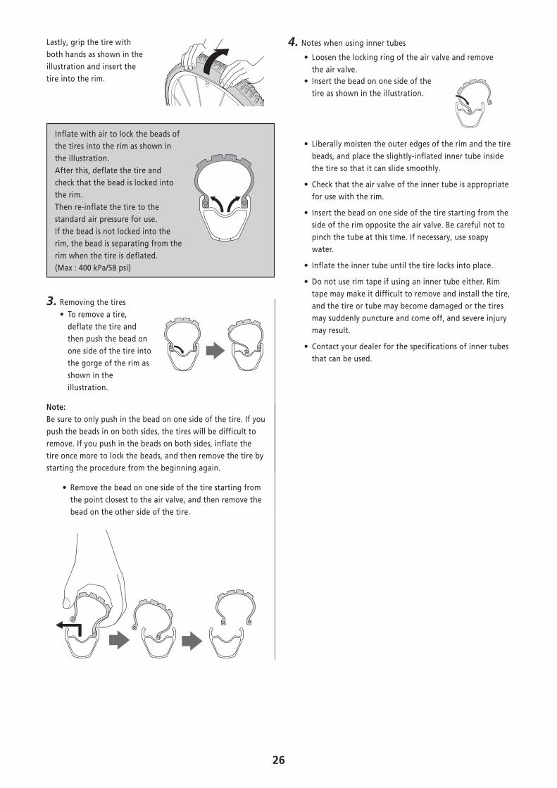
Lastly, grip the tire with both hands as shown in the illustration and insert the tire into the rim.
Inflate with air to lock the beads of the tires into the rim as shown in the illustration. After this, deflate the tire and check that the bead is locked into the rim. Then re-inflate the tire to the standard air pressure for use. If the bead is not locked into the rim, the bead is separating from the rim when the tire is deflated. (Max : 400 kPa/58 psi)
3. Removing the tires • To remove a tire, deflate the tire and then push the bead on one side of the tire into the gorge of the rim as shown in the illustration.
Note:Be sure to only push in the bead on one side of the tire. If you push the beads in on both sides, the tires will be difficult to remove. If you push in the beads on both sides, inflate the tire once more to lock the beads, and then remove the tire by starting the procedure from the beginning again.
• Remove the bead on one side of the tire starting from the point closest to the air valve, and then remove the bead on the other side of the tire.
4. Notes when using inner tubes
• Loosen the locking ring of the air valve and remove the air valve.
• Insert the bead on one side of the tire as shown in the illustration.
• Liberally moisten the outer edges of the rim and the tire beads, and place the slightly-inflated inner tube inside the tire so that it can slide smoothly.
• Check that the air valve of the inner tube is appropriate for use with the rim.
• Insert the bead on one side of the tire starting from the side of the rim opposite the air valve. Be careful not to pinch the tube at this time. If necessary, use soapy water.
• Inflate the inner tube until the tire locks into place.
• Do not use rim tape if using an inner tube either. Rim tape may make it difficult to remove and install the tire, and the tire or tube may become damaged or the tires may suddenly puncture and come off, and severe injury may result.
• Contact your dealer for the specifications of inner tubes that can be used.

Please note: specifications are subject to change for improvement without notice. (English) © May 2017 by Shimano Inc. ITP