Msv f2 dn15-400
16
Data sheet Manual presetting valves MSV-F2, PN 16/25, DN 15 - 400 SMT/SI VD.B1.G8.02 © Danfoss 08/2009 1 Description MSV-F2 valves are manual presetting valves. They are used for balancing the flow in heating and cooling installations. The valves have position indicator and stroke limiter as standard. Hood of spindle is integrated with stroke limiter. Setting can be locked. Valve characteristics are set up in measuring unit PFM 3000. Valves are free of asbestos. Shut-off function. Main data: • DN 15 - 400 • PN 16: - Flow temperature: –10 °C … 130 °C • PN 25: - Flow temperature: –10 °C … 150 °C • Valves are mounted on flow or return pipe. MSV-F2 DN 15-150 Cooling installation (flow) with manual presetting valves. In order to balance the cooling installation manual presetting valves should be mounted under each riser, branch and single terminal unit (MSV-C). Applications MSV-F2 DN 200-400 In constant flow installations MSV valves keeps constant pressure drop. Its value may be set on several levels depending on presetting.
-
Upload
logenatech -
Category
Technology
-
view
60 -
download
1
Transcript of Msv f2 dn15-400

Data sheet
Manual presetting valvesMSV-F2, PN 16/25, DN 15 - 400
SMT/SI VD.B1.G8.02 © Danfoss 08/2009 1
Description
MSV-F2 valves are manual presetting valves. They are used for balancing the flow in heating and cooling installations.
The valves have position indicator and stroke limiter as standard. Hood of spindle is integrated with stroke limiter.
Setting can be locked. Valve characteristics are set up in measuring unit PFM 3000.
Valves are free of asbestos.
Shut-off function.
Main data:• DN 15 - 400• PN 16: - Flow temperature: –10 °C … 130 °C• PN 25:
- Flow temperature: –10 °C … 150 °C• Valves are mounted on flow or return pipe.
MSV-F2 DN 15-150
Cooling installation (flow) with manual presetting valves. In order to balance the cooling installation manual presetting valves should be mounted under each riser, branch and single terminal unit (MSV-C).
Applications
MSV-F2 DN 200-400
In constant flow installations MSV valves keeps constant pressure drop. Its value may be set on several levels depending on presetting.
2 VD.B1.G8.02 © Danfoss 08/2009 SMT/SI
Data sheet Manual presetting valves MSV-F2
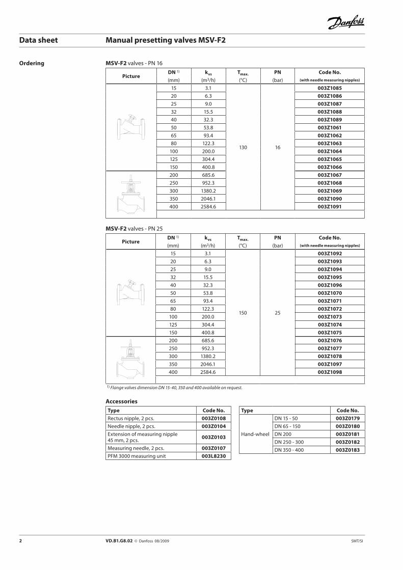
Ordering MSV-F2 valves - PN 16
PictureDN 1) kvs Tmax. PN Code No.
(mm) (m3/h) (°C) (bar) (with needle measuring nipples)
15 3.1
130 16
003Z1085
20 6.3 003Z1086
25 9.0 003Z1087
32 15.5 003Z1088
40 32.3 003Z1089
50 53.8 003Z1061
65 93.4 003Z1062
80 122.3 003Z1063
100 200.0 003Z1064
125 304.4 003Z1065
150 400.8 003Z1066
200 685.6 003Z1067
250 952.3 003Z1068
300 1380.2 003Z1069
350 2046.1 003Z1090
400 2584.6 003Z1091
MSV-F2 valves - PN 25
PictureDN 1) kvs Tmax. PN Code No.
(mm) (m3/h) (°C) (bar) (with needle measuring nipples)
15 3.1
150 25
003Z1092
20 6.3 003Z1093
25 9.0 003Z1094
32 15.5 003Z1095
40 32.3 003Z1096
50 53.8 003Z1070
65 93.4 003Z1071
80 122.3 003Z1072
100 200.0 003Z1073
125 304.4 003Z1074
150 400.8 003Z1075
200 685.6 003Z1076
250 952.3 003Z1077
300 1380.2 003Z1078
350 2046.1 003Z1097
400 2584.6 003Z1098
1) Flange valves dimension DN 15-40, 350 and 400 available on request.
Accessories
Type Code No.
Rectus nipple, 2 pcs. 003Z0108
Needle nipple, 2 pcs. 003Z0104
Extension of measuring nipple 45 mm, 2 pcs. 003Z0103
Measuring needle, 2 pcs. 003Z0107
PFM 3000 measuring unit 003L8230
Type Code No.
Hand-wheel
DN 15 - 50 003Z0179
DN 65 - 150 003Z0180
DN 200 003Z0181
DN 250 - 300 003Z0182
DN 350 - 400 003Z0183
SMT/SI VD.B1.G8.02 © Danfoss 08/2009 3
Data sheet Manual presetting valves MSV-F2
MSV-F2 valves - PN 16
Nominal diameter DN 15 20 25 32 40 50 65 80 100 125 150 200 250 300 350 400
kvs (m3/h) 3.1 6.3 9.0 15.5 32.3 53.8 93.4 122.3 200.0 304.4 400.8 685.6 952.3 1380.2 2046.1 2584.6
Nominal pressure (bar) 16
Max. pressure drop (bar) 1.5
Leakage rate Grade A; According to ISO5208, Table 5 (No visible leakage)
Flow medium Water and water mixtures with secondary coolants (like glycols)* for closed heating and cooling systems
Max. flow temperature (°C) 130
Connections Flanges according to EN 1092-2
Weight (kg) 2.3 2.9 3.8 5.6 7.2 9.4 17 21 32 43 56 231 354 497 747 890
Material of body Cast iron EN-GJL 250 (GG 25)
Seat sealing EPDM
Material of cone CW602N CuSn5Zn5Pb5 Casted stainless steel* Please verefy compability between materials and secondary coolants with supplier.
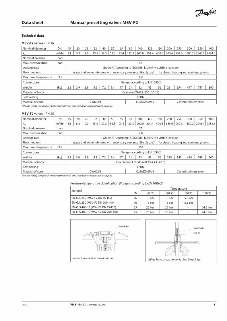
Technical data
MSV-F2 valves - PN 25
Nominal diameter DN 15 20 25 32 40 50 65 80 100 125 150 200 250 300 350 400
kvs (m3/h) 3.1 6.3 9.0 15.5 32.3 53.8 93.4 122.3 200.0 304.4 400.8 685.6 952.3 1380.2 2046.1 2584.6
Nominal pressure (bar) 25
Max. pressure drop (bar) 2.0
Leakage rate Grade A; According to ISO5208, Table 5 (No visible leakage)
Flow medium Water and water mixtures with secondary coolants (like glycols)* for closed heating and cooling systems
Max. flow temperature (°C) 150
Connections Flanges according to EN 1092-2
Weight (kg) 2.3 3.0 3.8 5.8 7.2 9.4 17 21 33 43 56 228 345 488 748 900
Material of body Ductile iron EN-GJS 400-15 (GGG 40.3)
Seat sealing EPDM
Material of cone CW602N CuSn5Zn5Pb5 Casted stainless steel* Please verefy compability between materials and secondary coolants with supplier.
Pressure-temperature classification (flanges according to EN 1092-2)
MaterialPN
Temperature
-10 °C 120 °C 130 °C 150 °C
EN-GJL 250 (MSV-F2 DN 15-150) 16 16 bar 16 bar 15.5 bar -
EN-GJL 250 (MSV-F2 DN 200-400) 16 16 bar 16 bar 15.5 bar -
EN-GJS 400-15 (MSV-F2 DN 15-150) 25 25 bar 25 bar - 24.3 bar
EN-GJS 400-15 (MSV-F2 DN 200-400) 25 25 bar 25 bar - 24.3 bar
Valves have stroke limiter locked by lock-nutValves have built in flow limitation
4 VD.B1.G8.02 © Danfoss 08/2009 SMT/SI
Data sheet Manual presetting valves MSV-F2
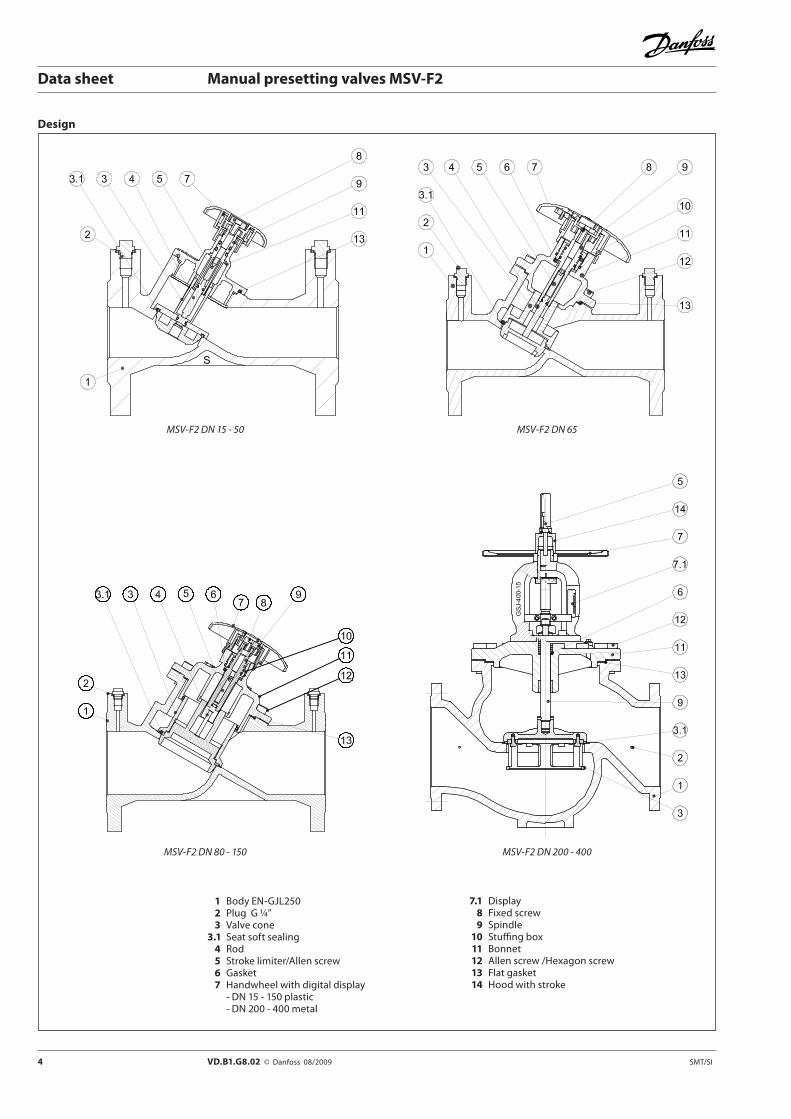
Design
1 Body EN-GJL250 2 Plug G ¼” 3 Valve cone 3.1 Seat soft sealing 4 Rod 5 Stroke limiter/Allen screw 6 Gasket 7 Handwheel with digital display - DN 15 - 150 plastic - DN 200 - 400 metal
MSV-F2 DN 15 - 50 MSV-F2 DN 65
MSV-F2 DN 80 - 150 MSV-F2 DN 200 - 400
7.1 Display 8 Fixed screw 9 Spindle 10 Stuffing box 11 Bonnet 12 Allen screw /Hexagon screw 13 Flat gasket 14 Hood with stroke

2D5D
SMT/SI VD.B1.G8.02 © Danfoss 08/2009 5
Data sheet Manual presetting valves MSV-F2
MSV-F2 DN 65∆p = 0.6 barHand wheel setting: 3.0Flow: 16.8 m3/h30% glycolQcorr. = 16.8 m3/h × 0.953 = 16.0 m3/hIt refers to all types of valves.
Ethylenglycol correction factor
Formula: C2H6O2Density at 20 °C: ρwater = 1 kg/dm3
ρglycol = 1.338 kg/dm3 glycolwater
watercorr.
ρglycol of Shareρwater of Share
×+×=
Setting
Installation Always install the valve with the arrow on the body in the same direction as the flow. In order to avoid turbulence, which will affect the measuring accuracy, it is recommended to have a straight length of pipe up and down stream from the valve as shown (D - diameter of pipe).
The influence of turbulence, if our recommendations are not adhered to, can influence the flow up to 20%.
Ethylenglycol part xg (%) 0 10 20 30 40 50 60 70 80 90 100
Correction factor 1.0 0.983 0.968 0.953 0.939 0.925 0.912 0.899 0.887 0.876 0.864

6 VD.B1.G8.02 © Danfoss 08/2009 SMT/SI
Data sheet Manual presetting valves MSV-F2
Sizing
Example:MSV-F2 DN 65Q = 16 m3/h∆p = 5 kPa
Calculation of setting for valve:In the diagram a straight line connecting the bars for flow 16 m3/h, differential pressure 5 kPa and kv value shows the relationship between these three variables.
A horizontal line from intersection with the kv bar shows the presetting value for each valve size.
Result: presetting 7.0

SMT/SI VD.B1.G8.02 © Danfoss 08/2009 7
Data sheet Manual presetting valves MSV-F2
Flow diagrams DN 15 / PN 16 / PN 25
Setting kv-value
1 0.45
2 1.26
3 2.73
4 3.09
Max. permissible differential pressure in throttling function 1.5/2.0 bar.Max. permissible flow speed: ≤ 4 m/sCondition:
• The flow must be free of cavitation.
Flow characteristic
DN 20 / PN 16 / PN 25
Setting kv-value
1 0.54
2 2.48
3 5.11
4 6.26
Max. permissible differential pressure in throttling function 1.5/2.0 bar.Max. permissible flow speed: ≤ 4 m/sCondition:
• The flow must be free of cavitation.
Flow characteristic

8 VD.B1.G8.02 © Danfoss 08/2009 SMT/SI
Data sheet Manual presetting valves MSV-F2
Flow diagrams (continued) DN 25 / PN 16 / PN 25
Setting kv-value
1 1.61
2 6.0
3 8.38
4 9.01
Max. permissible differential pressure in throttling function 1.5/2.0 bar.Max. permissible flow speed: ≤ 4 m/sCondition:
• The flow must be free of cavitation.
Flow characteristic
DN 32 / PN 16 / PN 25
Setting kv-value
1 3.53
2 7.56
3 12.32
4 15.54
Max. permissible differential pressure in throttling function 1.5/2.0 bar.Max. permissible flow speed: ≤ 4 m/sCondition:
• The flow must be free of cavitation.
Flow characteristic

SMT/SI VD.B1.G8.02 © Danfoss 08/2009 9
Data sheet Manual presetting valves MSV-F2
Flow diagrams (continued) DN 40 / PN 16 / PN 25
Setting kv-value
1 4.19
2 9.98
3 16.42
4 22.13
5 28.14
6 32.31
Max. permissible differential pressure in throttling function 1.5/2.0 bar.Max. permissible flow speed: ≤ 4 m/sCondition:
• The flow must be free of cavitation.
Flow characteristic
DN 50 / PN 16 / PN 25
Setting kv-value
1 7.4
2 15.8
3 26.7
4 36.9
5 46.2
6 53.8
Max. permissible differential pressure in throttling function 1.5/2.0 bar.Max. permissible flow speed: ≤ 4 m/sCondition:
• The flow must be free of cavitation.
Flow characteristic
10 VD.B1.G8.02 © Danfoss 08/2009 SMT/SI
Data sheet Manual presetting valves MSV-F2
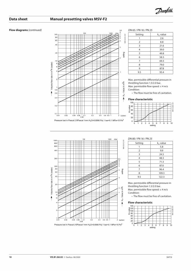
DN 65 / PN 16 / PN 25
Setting kv-value
1 2.6
2 8.8
3 21.6
4 39.0
5 49.8
6 58.5
7 69.3
8 79.0
9 87.8
9.5 93.4
Max. permissible differential pressure in throttling function 1.5/2.0 bar.Max. permissible flow speed: ≤ 4 m/sCondition:
• The flow must be free of cavitation.
Flow characteristic
DN 80 / PN 16 / PN 25
Setting kv-value
1 5.8
2 9.9
3 24.5
4 48.5
5 71.3
6 87.0
7 96.4
8 109.3
9.5 122.3
Max. permissible differential pressure in throttling function 1.5/2.0 bar.Max. permissible flow speed: ≤ 4 m/sCondition:
• The flow must be free of cavitation.
Flow characteristic
Flow diagrams (continued)
SMT/SI VD.B1.G8.02 © Danfoss 08/2009 11
Data sheet Manual presetting valves MSV-F2
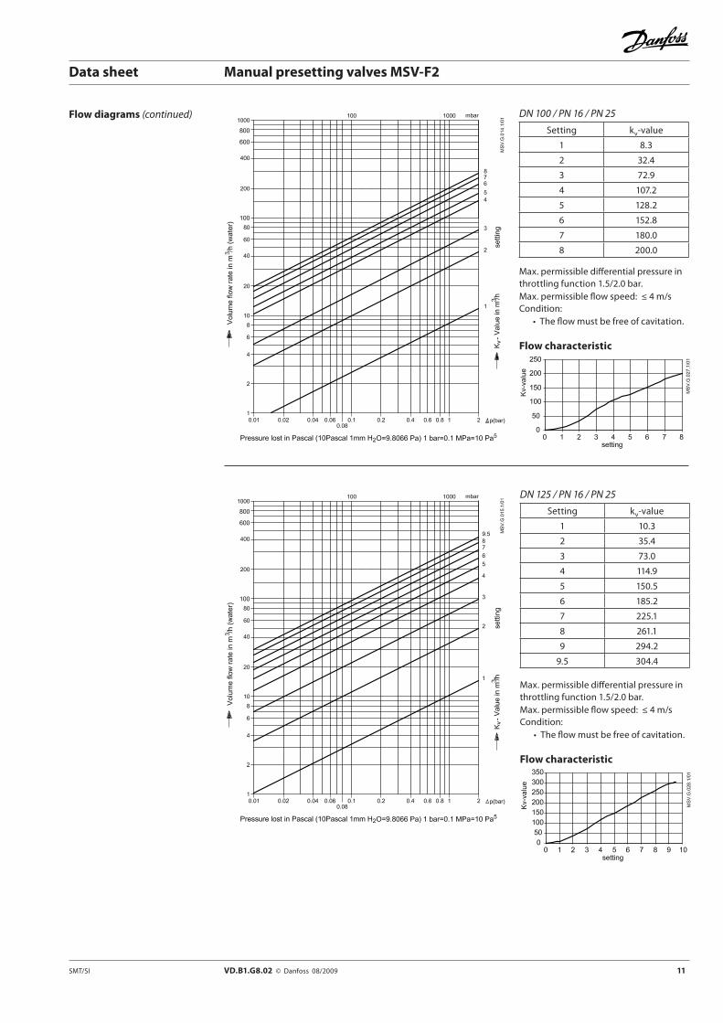
Flow diagrams (continued) DN 100 / PN 16 / PN 25
Setting kv-value
1 8.3
2 32.4
3 72.9
4 107.2
5 128.2
6 152.8
7 180.0
8 200.0
Max. permissible differential pressure in throttling function 1.5/2.0 bar.Max. permissible flow speed: ≤ 4 m/sCondition:
• The flow must be free of cavitation.
Flow characteristic
DN 125 / PN 16 / PN 25
Setting kv-value
1 10.3
2 35.4
3 73.0
4 114.9
5 150.5
6 185.2
7 225.1
8 261.1
9 294.2
9.5 304.4
Max. permissible differential pressure in throttling function 1.5/2.0 bar.Max. permissible flow speed: ≤ 4 m/sCondition:
• The flow must be free of cavitation.
Flow characteristic

12 VD.B1.G8.02 © Danfoss 08/2009 SMT/SI
Data sheet Manual presetting valves MSV-F2
Flow diagrams (continued) DN 150 / PN 16 / PN 25
Setting kv-value
1 21.4
2 48.5
3 99.8
4 162.0
5 214.0
6 260.9
7 304.1
8 354.6
9.5 400.8
Max. permissible differential pressure in throttling function 1.5/2.0 bar.Max. permissible flow speed: ≤ 4 m/sCondition:
• The flow must be free of cavitation.
Flow characteristic
DN 200 / PN 16 / PN 25
Setting kv-value
2 198.2
3 305.3
4 397.5
5 474.0
6 530.4
7 586.8
8 645.9
10 685.6
Max. permissible differential pressure in throttling function 1.5/2.0 bar.Max. permissible flow speed: ≤ 4 m/sCondition:
• The flow must be free of cavitation.
Flow characteristic
SMT/SI VD.B1.G8.02 © Danfoss 08/2009 13
Data sheet Manual presetting valves MSV-F2
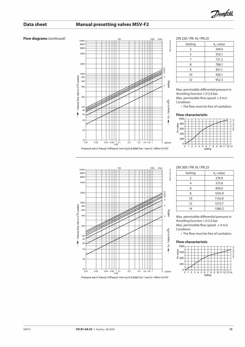
Flow diagrams (continued) DN 250 / PN 16 / PN 25
Setting kv-value
3 299.4
5 553.1
7 721.2
8 788.1
9 851.1
10 926.1
12 952.3
Max. permissible differential pressure in throttling function 1.5/2.0 bar.Max. permissible flow speed: ≤ 4 m/sCondition:
• The flow must be free of cavitation.
Flow characteristic
DN 300 / PN 16 / PN 25
Setting kv-value
2 270.9
4 575.8
6 856.0
8 1035.9
10 1142.8
12 1273.7
14 1380.2
Max. permissible differential pressure in throttling function 1.5/2.0 bar.Max. permissible flow speed: ≤ 4 m/sCondition:
• The flow must be free of cavitation.
Flow characteristic
14 VD.B1.G8.02 © Danfoss 08/2009 SMT/SI
Data sheet Manual presetting valves MSV-F2
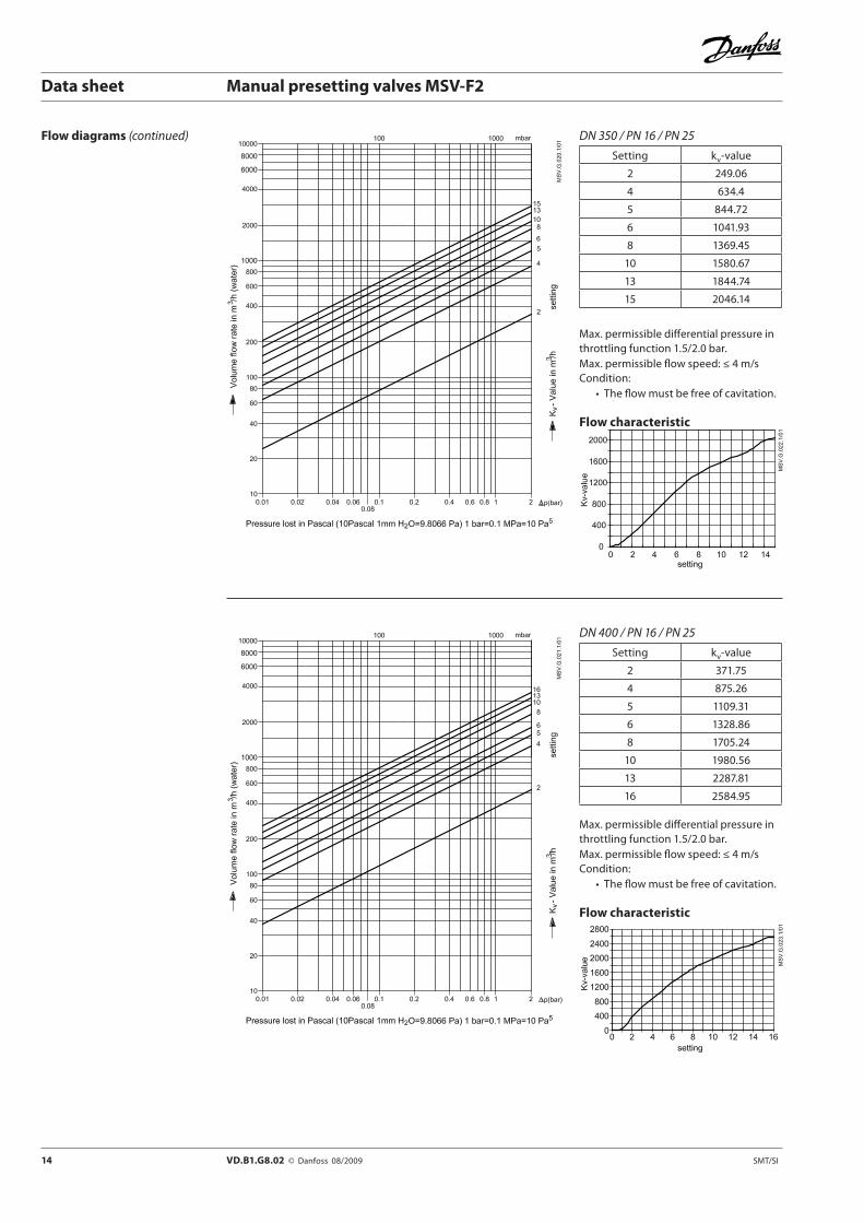
Flow diagrams (continued) DN 350 / PN 16 / PN 25
Setting kv-value
2 249.06
4 634.4
5 844.72
6 1041.93
8 1369.45
10 1580.67
13 1844.74
15 2046.14
Max. permissible differential pressure in throttling function 1.5/2.0 bar.Max. permissible flow speed: ≤ 4 m/sCondition:
• The flow must be free of cavitation.
Flow characteristic
DN 400 / PN 16 / PN 25
Setting kv-value
2 371.75
4 875.26
5 1109.31
6 1328.86
8 1705.24
10 1980.56
13 2287.81
16 2584.95
Max. permissible differential pressure in throttling function 1.5/2.0 bar.Max. permissible flow speed: ≤ 4 m/sCondition:
• The flow must be free of cavitation.
Flow characteristic

SMT/SI VD.B1.G8.02 © Danfoss 08/2009 15
Data sheet Manual presetting valves MSV-F2
Dimensions
DNL H1 H2 ØA
PN 16 PN 25
ØD ØK n × Ød ØD ØK n × Ød
mm
15 130 80 - 78 95 65 4 × 14 95 65 4 × 14
20 150 90 - 78 105 75 4 × 14 105 75 4 × 14
25 160 105 - 78 115 85 4 × 14 115 85 4 × 14
32 180 110 - 78 140 100 4 × 19 140 100 4 × 19
40 200 125 - 78 150 110 4 × 19 150 110 4 × 19
50 230 125 - 78 165 125 4 × 19 165 125 4 × 19
65 290 187 - 140 185 145 4 × 19 185 145 8 × 19
80 310 205 - 140 200 160 8 × 19 200 160 8 × 19
100 350 222 - 140 220 180 8 × 19 235 190 8 × 23
125 400 251 - 140 250 210 8 × 19 270 220 8 × 28
150 480 247 - 140 285 240 8 × 23 300 250 8 × 28
200 600 721 533 360 340 295 12 × 23 360 310 12 × 28
250 730 808 617 400 405 355 12 × 28 425 370 12 × 31
300 850 855 664 400 460 410 12 × 28 485 430 16 × 31
350 980 910 729 500 520 470 16 × 28 555 490 16 × 34
400 1100 960 762 500 580 525 16 × 31 620 550 16 × 37
Remark: “n” is number of holes in the flange.
MSV-F2 DN 15 - 50 MSV-F2 DN 65
MSV-F2 DN 80 - 150 MSV-F2 DN 200 - 400

16 VD.B1.G8.02 Prepared by Danfoss A/S © 08/2009
Data sheet Manual presetting valves MSV-F2
![2007 ANNUAL REPORT [E] - MSV Life · 2020. 6. 12. · Group (“MSV”), notwithstanding some ... we seek to exercise in our investment operations. During 2007, MSV continued to experience](https://static.fdocuments.us/doc/165x107/601191cba6c5644c480c8a3a/2007-annual-report-e-msv-life-2020-6-12-group-aoemsva-notwithstanding.jpg)