MSRE Design Features...6 MSRE Design Features The MSRE Vessel and Graphite Moderator MSRE Graphite...
13
ORNL is managed by UT-Battelle for the US Department of Energy ORNL is managed by UT-Battelle for the US Department of Energy MSRE Design Features M. Scott Greenwood, Ph.D. Advanced Reactor Systems & Safety Reactor & Nuclear Systems Division Nuclear Science & Engineering Directorate Molten Salt Reactor Workshop 2017 Session 3 – Deep Dive on MSRE Design, Operations, and Authorization October 3–4, 2017
Transcript of MSRE Design Features...6 MSRE Design Features The MSRE Vessel and Graphite Moderator MSRE Graphite...

ORNL is managed by UT-Battelle for the US Department of EnergyORNL is managed by UT-Battelle for the US Department of Energy
MSRE Design Features
M. Scott Greenwood, Ph.D.Advanced Reactor Systems & SafetyReactor & Nuclear Systems DivisionNuclear Science & Engineering Directorate
Molten Salt Reactor Workshop 2017
Session 3 – Deep Dive on MSRE Design, Operations, and Authorization
October 3–4, 2017

2 MSRE Design Features
The 8 MWt MSR Experiment (MSRE) Reactor
Source: ORNL-TM-728
• Red – fuel salt flow• Yellow – coolant salt flow• No power conversion – heat
dissipated to atmosphere• Major system components
shownDrain Tanks
Reactor Vessel
Freeze Flange
Fuel Pump
Freeze Valve

3 MSRE Design Features
MSRE Reactor Cavity from Above
Source: ORNL-TM-728 ORNL Photo 66372
Fuel Pump Reactor Vessel
Heat Exchanger
Coolant Salt Loop
Fuel Salt Loop
Freeze Flanges

4 MSRE Design Features
Extensive Testing Enabled the Success of the MSRE
• Numerous experimental facilities employed over several years leading up to the MSRE
• Facilities studied salt behavior, material development, corrosion, radiation effects, etc.
• Molten Salt Reactor Experiment (1960 – 1969)– 8 MWt– Alloy N vessel/piping– Single Region Core, Graphite moderated (thermal)– >13,000 full power hoursOperation:– 1965 (June) First Criticality– 1966 (Dec) First Full Power Operation– 1968 (Oct) First Operation on U-233– 1969 (Dec) Shutdown
Battery of natural circulation loops as of 1957
ORR In-Pile Fuel Salt Loop
5 MSRE Design Features
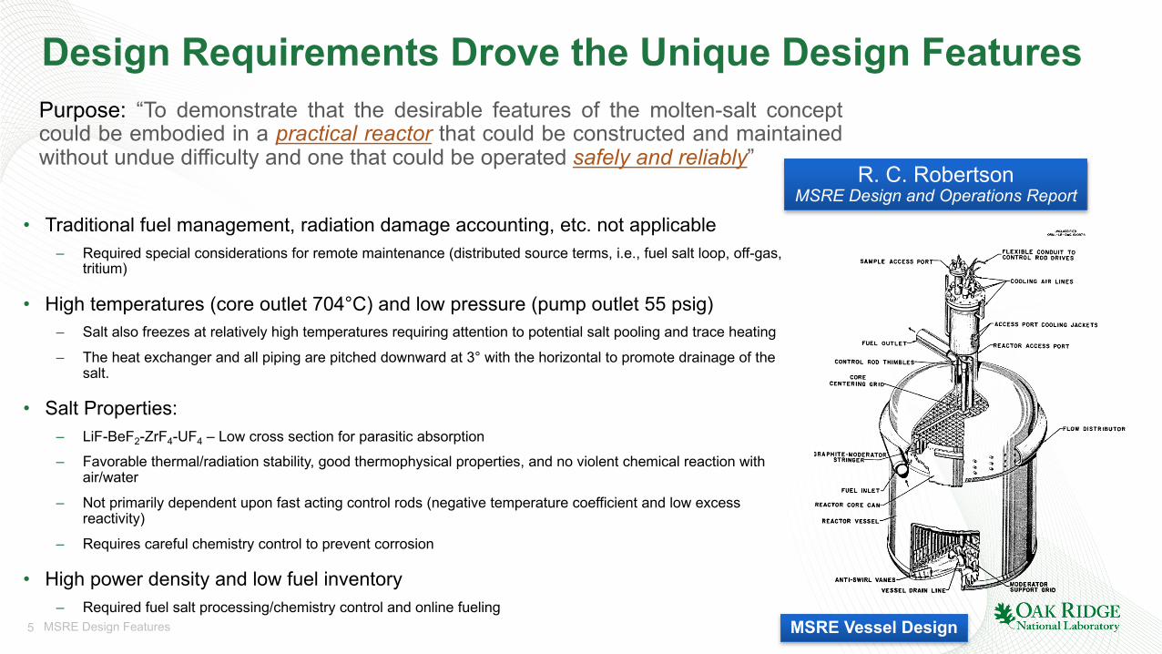
Design Requirements Drove the Unique Design Features
• Traditional fuel management, radiation damage accounting, etc. not applicable– Required special considerations for remote maintenance (distributed source terms, i.e., fuel salt loop, off-gas,
tritium)
• High temperatures (core outlet 704°C) and low pressure (pump outlet 55 psig)– Salt also freezes at relatively high temperatures requiring attention to potential salt pooling and trace heating
– The heat exchanger and all piping are pitched downward at 3° with the horizontal to promote drainage of the salt.
• Salt Properties:– LiF-BeF2-ZrF4-UF4 – Low cross section for parasitic absorption
– Favorable thermal/radiation stability, good thermophysical properties, and no violent chemical reaction with air/water
– Not primarily dependent upon fast acting control rods (negative temperature coefficient and low excess reactivity)
– Requires careful chemistry control to prevent corrosion
• High power density and low fuel inventory– Required fuel salt processing/chemistry control and online fueling
Purpose: “To demonstrate that the desirable features of the molten-salt conceptcould be embodied in a practical reactor that could be constructed and maintainedwithout undue difficulty and one that could be operated safely and reliably”
R. C. RobertsonMSRE Design and Operations Report
MSRE Vessel Design

6 MSRE Design Features
The MSRE Vessel and Graphite Moderator
MSRE Graphite Moderator55 in. diameter, 64 in. tall
Typical Stringer Arrangement
• The reactor core is formed of 617 2-in.×2-in. graphite stringers– 513 full and 104 fractional-sized blocks
at the periphery– Upper stringer surfaces are tapered to
prevent salt pooling• Stringers are mounted in a
vertical, close-packed array– Half-channel salt flow passages are
machined in the four faces of each stringer
– Total of 1140 fuel passages• Graphite stringers float in salt
– Stringer lower end in 1 in. dowels– Use of retainer rings to limit radial
mobility (i.e., floating and thermal expansion)
Source: ORNL-TM-728
MSRE Vessel: 5 ft diameter, 8 ft tall(20 ft3 fuel salt and 70 ft3 graphite)

7 MSRE Design Features
MSRE Reactivity Control System… not a Safety System• 3 control rods provide adjustment for reactivity
– Control flux at low power and dampen temperature swings at power, not required for fast-acting, nuclear safety purposes
– Power level determined by coolant loop ΔT (via radiator blower) and flow.
– Complete reactor shutdown accomplished by draining fuel salt
• Curved “dog-leg” guide tubes eliminate straight line of sight for radiation to control rod drive hardware through the tube
• Control rod guide tube separates control elements from direct contact with salt and go through bored graphite stringers
MSRE Control Rod and Drive Assembly
Source: ORNL-4123
Source: ORNL-TM-728
MSRE Control ElementsGd2O3-30%Al2O3 bushings on
flexible stainless steel hose
8 MSRE Design Features
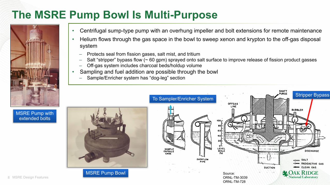
The MSRE Pump Bowl Is Multi-Purpose
Source: ORNL-TM-3039ORNL-TM-728
Stripper BypassTo Sampler/Enricher System
MSRE Pump Bowl
• Centrifugal sump-type pump with an overhung impeller and bolt extensions for remote maintenance• Helium flows through the gas space in the bowl to sweep xenon and krypton to the off-gas disposal
system– Protects seal from fission gases, salt mist, and tritium– Salt “stripper” bypass flow (~ 60 gpm) sprayed onto salt surface to improve release of fission product gasses– Off-gas system includes charcoal beds/holdup volume
• Sampling and fuel addition are possible through the bowl– Sample/Enricher system has “dog-leg” section
MSRE Pump withextended bolts

9 MSRE Design Features
Piping Required Special Freeze Flange Designs
• Freeze flange (Alloy-N) type– Create tight seal which prevents salt contact with ring-joint gasket
• Access hole at sight of gasket for helium buffer gas and leak detection– Two holes in nickel gasket to enable buffer gas to access both sides
• Alloy-N salt screen– Located in the 0.050 in. gap– Improves salt solidification (passively cooled)– Provides a convenient intact cake for salt removal during maintenance
• Clamps hydraulically seal flange– Affords a more constant gasket loading during thermal cycling than bolting
• Male end of clamp installed facing “uphill”– Limits salt pooling
Source: ORNL-TM-728
Freeze Flange and Clamp

10 MSRE Design Features
MSRE Freeze Valves Control Flow to the Drain Tanks
• Flow of salt in the drain, fill, and processing systems is controlled by freezing or thawing a short plug of salt
– 12 freeze valves located throughout the plant
• Freeze valves preferred since reliable mechanical closure valve unavailable
– Development began in 1960– 1.5 in. pipe flattened for a length of ~ 2 in.– Installed with flat surfaces horizontal (avoid air pockets)– Operations not hampered by “slow” response and lack of “off-on”
functionality
• Three operational modes– Deep frozen: heaters adjusted to maintain 200–260°C without cooling air– Thawed: heaters adjusted to maintain 650°C without cooling air
(active: ~1-2 min., passive: ~10 min.)– Frozen: Heaters remained in thawed condition but cooling gas flow
adjusted to hold just frozen to allow for rapid thaw
• Draining a small amount of fuel salt shuts down the reactor– Complete fuel salt drain in approximately 30 minutes
Location of freeze valves
Freeze valve schematic
Source: ORNL-TM-3039
11 MSRE Design Features
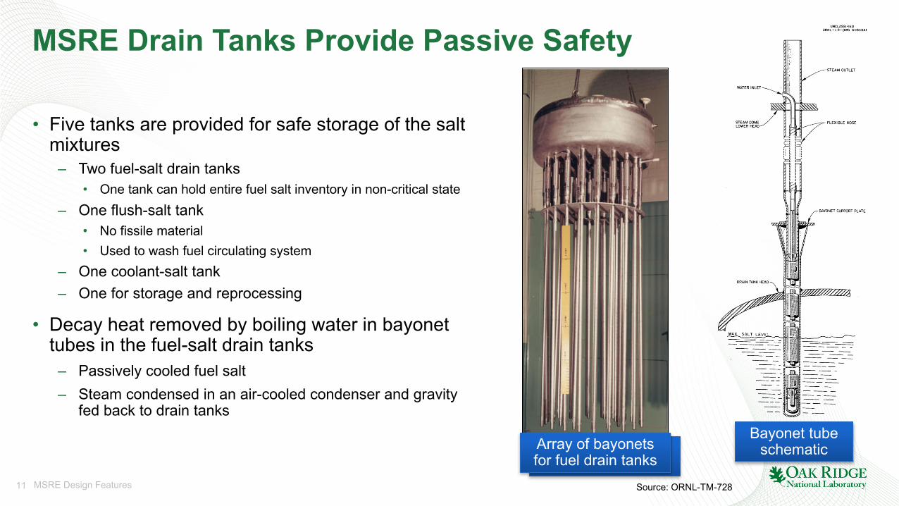
MSRE Drain Tanks Provide Passive Safety
• Five tanks are provided for safe storage of the salt mixtures
– Two fuel-salt drain tanks• One tank can hold entire fuel salt inventory in non-critical state
– One flush-salt tank• No fissile material• Used to wash fuel circulating system
– One coolant-salt tank– One for storage and reprocessing
• Decay heat removed by boiling water in bayonet tubes in the fuel-salt drain tanks
– Passively cooled fuel salt– Steam condensed in an air-cooled condenser and gravity
fed back to drain tanks
Source: ORNL-TM-728
Array of bayonets for fuel drain tanks
Array of bayonets for fuel drain tanks
Bayonet tube schematic

12 MSRE Design Features
A Few Takeaways…
The MSRE…• … was an all-encompassing, mature research project with extensive testing and
documentation• … successfully demonstrated numerous technologies and techniques for high-
temperature molten salt applications– The topics covered in this presentation only scratch the surface of the various design features
and facilities that went into the MSRE
• … technologies are foundational to modern MSR designs• … demonstrated that MSRs are indeed practical to be constructed and able to be
operated safely and reliably
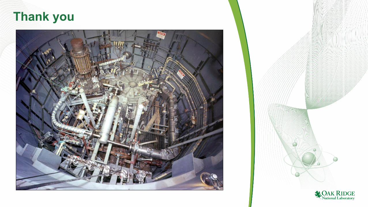
Thank you


![CATALOG OF NUCLEAR REACTOR CONCEPTS [Disc 1]...moderator, and thorium tetrafluoride can be added for conversion. Graphite and beryllium are commonly used as structured moder ators.](https://static.fdocuments.us/doc/165x107/5e478082e5cfa3002f70fc6a/catalog-of-nuclear-reactor-concepts-disc-1-moderator-and-thorium-tetrafluoride.jpg)