MSR provisional System Steering committee
24
MSR provisional System Steering committee GIF Symposium Chiba May 19, 2015 J. Serp, France
Transcript of MSR provisional System Steering committee

MSR provisional System Steering committee
GIF Symposium
Chiba
May 19, 2015
J. Serp, France

Status of MSR development Slide 2 GIF Symposium, Chiba, May 2015
Studied Concepts
MSFR
MOSART Two reactor concepts using molten salt are
discussed in GIF MSR meetings
– Molten salt reactors, in which the salt is at
the same time the fuel and the cooling liquid
» MSR MOU Signatories France and EU
work on MSFR (Molten Salt Fast Reactor)
» Russian Federation works on MOSART
(Molten Salt Actinide Recycler &
Transmuter). Russian Federation joined
the Memorandum of Understanding
(11/2013)
– Solid fueled Reactors cooled by molten salt
» USA and China work on FHR (fluoride-
salt-cooled high-temperature reactor)
concepts and are Observers to the PSSC
FHR 3,400 MWth
High temperature (750 0C)
Low pressure (1 bar)
1000 MWe

Status of MSR development Slide 3 GIF Symposium, Chiba, May 2015
Reference concept :
The first Molten Salt Reactors (MSR) developed in the USA (1960s
and 1970s) were thermal-neutron-spectrum graphite-moderated
concepts
Since 2005, European R&D interest has focused on fast neutron
MSR (MSFR) as a long term alternative to solid-fueled fast
neutrons reactors
General characteristics of MSR
• Molten fluorides as fuel fluid (no loading pattern)
• Low-pressure and high boiling-point coolant
• Possibility to drain fuel passively towards non-critical volumes
• On-site fuel reprocessing unit
Specific features of MSFR
• Strongly negative reactivity feedback coefficients (thermal and void)
• Reprocessing needs decreased (from several m3 to 40 liters/day)
• No graphite elements in the core (maintenance)
From thermal to fast neutron spectrum
MSRE
MSFR

Status of MSR development Slide 4 GIF Symposium, Chiba, May 2015
GIF MSR Project
• A Provisional Project Management Board has been set up
– Two meetings per year where members and observers report on their
activities and recent progresses
• The project is devoted to Molten Salt Reactors
– Information is also exchanged on solid fueled reactors cooled by
molten salt
• The various molten salt reactor projects like FHR, MOSART, MSFR, and
TMSR have common themes in basic R&D areas, of which the most
prominent are:
o liquid salt technology,
o materials behavior,
o the fuel and fuel cycle chemistry and modeling,
o the numerical simulation and safety design aspects of the reactor

Status of MSR development Slide 5 GIF Symposium, Chiba, May 2015
SAMOFAR Project – Safety Assessment of a MOlten salt FAst Reactor
5 technical work-packages:
WP1 Integral safety approach and system integration
WP2 Physical and chemical properties required for safety
analysis
WP3 Proof of concept of key safety features
WP4 Numerical assessment of accidents and transients
WP5 Safety evaluation of the chemical processes and
plant
Collaborations (1/2)
SAMOFAR will deliver the experimental proof of the following key safety features:
The freeze plug and draining of the fuel salt
New materials and new coatings to materials
Measurement of safety related data of the fuel salt
The dynamics of natural circulation of (internally heated) fuel salts
The reductive extraction processes to extract lanthanides and actinides from the fuel salt
4 years (2015-2019), 3,5 M€
Partners: TU-Delft (leader), CNRS, JRC-ITU, CIRTEN (POLIMI, POLITO), IRSN, AREVA,
CEA, EDF, KIT + PSI + CINVESTAV

Status of MSR development Slide 6 GIF Symposium, Chiba, May 2015
US and China Are Initiating a Cooperative Research and
Development Agreement (CRADA) on FHRs
Collaboration supports the US-China memorandum of understanding on
cooperation in civilian nuclear energy science and technology
ORNL and the Shanghai Institute of Applied Physics (SINAP) are the lead
organizations
Project is intended to benefit both countries through more efficiently and
rapidly advancing a reactor class of common interest
FHR remain at a pre-commercial level of maturity
– All of the results are intended to be openly available
– Project is scheduled to end after SINAP’s higher-power test reactor has completed its
operational testing program
Collaboration includes research and development to support the
evaluation, design, and licensing of a new reactor class
– Does not include fissile material separation technology
6
Collaborations (2/2)

Status of MSR development Slide 7 GIF Symposium, Chiba, May 2015
Liquid fueled-reactors
Which constraints for a liquid fuel?
• Melting temperature not too high
• High boiling temperature
• Low vapor pressure
• Good thermal and hydraulic properties
• Stability under irradiation
Best candidates = fluoride salt (LiF – 99.995% of 7Li)
Molten Salt Reactors
Thorium /233U Fuel Cycle
Neutronic properties of
F not favorable to the
U/Pu fuel cycle
There are some challenges for MSR that must be factored into design • Must keep system at high temperature to avoid salt freezing • Lifetime of components (graphite) • Chemical interactions with structural materials • The salt of choice (LiF based salt) produces tritium during operation
and requires Li enrichment • Complexity of a combined reactor and fuel processing system

Status of MSR development Slide 8 GIF Symposium, Chiba, May 2015
In the last decade ITU (European Commission) has developed an expertise in determination of High temperature properties of An fluorides and mixtures
Phase diagrams
Melting points
Vapour pressure
Heat capacity
Drop and DSC calorimeters up to
1800 K
Knudsen cell with MS up to 2800 K

Status of MSR development Slide 9 GIF Symposium, Chiba, May 2015
LiF-ThF4 system
• The vapour pressure of the end members LiF and ThF4 were measured, obtaining a very good agreement with the literature data. The appearance potential of the different species has been also measured.
Vapour pressure ThF4 Vapour pressure LiF
Ion AP (Lit.) AP (Meas.)
Th+ 39 eV 39.9 eV
ThF+ 30 eV 31.9 eV
ThF2+ 23 eV 23.9 eV
ThF3+ 14.5 eV 16.5 eV
1.E-02
1.E-01
1.E+00
1.E+01
1.E+02
1.E+03
1.E+04
1050 1100 1150 1200 1250 1300 1350 1400
Pre
ssu
re /
Pa
Temperature / K
P tot_FactSageP tot_measuredP LiF_ FactSageP LiF_measuredP Li2F2_FactSageP Li2F2_measuredP Li3F3_FactsageP Li3F3_measured
1.E-04
1.E-03
1.E-02
1.E-01
1.E+00
1.E+01
1.E+02
1.E+03
1000 1100 1200 1300 1400 1500
P r
ess
ure
/ P
a
Temperature / K
P tot _measured
P tot_FactSage

Status of MSR development Slide 10 GIF Symposium, Chiba, May 2015
10
LiF-ThF4-UF4-PuF3 ternary system assessed
Tmin=818,14 K
LiF-ThF4-PuF3 (69.6-28.6-1.8)

Status of MSR development Slide 11 GIF Symposium, Chiba, May 2015
Temperature, K 72,5LiF-7ThF4-20,5UF4 78LiF-7ThF4-15UF4
PuF3 CeF3 PuF3 CeF3
873 0,35±0,02 1,5±0,1 1,45±0,7 2,6±0,1
923 4,5±0,2 2,5±0,1 5,6±0,3 3,6±0,2
973 8,4±0,4 3,7±0,2 9,5±0,5 4,8±0,3
1023 9,4±0,5 3,9±0,2 10,5±0,6 5,0±0,3
Near the liquidus temperature for 78LiF-7ThF4-15UF4 and
72,5LiF-7ThF4-20,5UF4 salts, the CeF3 significantly displace
plutonium trifluoride
Isothermal saturation method
Actinides and lanthanides solubility measurements
Temperature, K Individual Solubility, mol.% Joint Solubility, mol. %
PuF3 UF4 PuF3 UF4
823 6.1±0.6 15.3±0.8 1.16±0.06 1.75±0.09
873 11.1±1.1 24.6±1.2 2.9±0.1 3.5±0.2
923 21.3±2.1 34.8±1.7 13.2±0.6 11.0±0.6
973 32.8±3.3 44.7±2.2 19.1±1.0 17.3±0.9
1023 - - 21.0±1.1 19.0±1.0
1073 - - 22.5±1.2 20.0±1.1
Individual and joint solubility of PuF3 and UF4 in LiF-NaF-KF eutectic, mol. %
Status of MSR development Slide 12 GIF Symposium, Chiba, May 2015
F
Ar
T
Ar
Ep
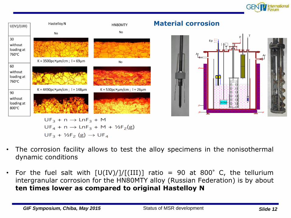
Cr3Te4
• The corrosion facility allows to test the alloy specimens in the nonisothermal dynamic conditions
• For the fuel salt with [U(IV)/]/[(III)] ratio = 90 at 800°C, the tellurium
intergranular corrosion for the HN80MTY alloy (Russian Federation) is by about ten times lower as compared to original Hastelloy N
Material corrosion

Status of MSR development Slide 13 GIF Symposium, Chiba, May 2015
Proposed Confinement barriers:
First barrier: fuel envelop, composed of two areas: critical and sub-critical areas
Second barrier: reactor vessel, also including the reprocessing and storage units
Third barrier: reactor wall, corresponding to the reactor building
LOLF accident (Loss of Liquid
Fuel) → no tools available for
quantitative analysis but qualitatively:
• Fuel circuit: complex
structure, multiple
connections
• Potential leakage: collectors
connected to draining tank
Design aspects impacting the MSFR safety analysis

Status of MSR development Slide 14 GIF Symposium, Chiba, May 2015
Safety analysis: accident types
Classified by the initiators of the transient:
TOP - Transient Over Power (or RAA - Reactivity Anomalies Accident)
LOF - Loss Of Flow (in the fuel circuit)
Pumps of the fuel salt & Pumps of the intermediate fluid
LOH - Loss Of Heat sink (in the fuel circuit)
Pumps of the fuel salt & cooling of the fuel salt
TLOP - Total Loss Of Power
OVC – Fuel salt OVer-Cooling
LOLF - Loss Of Liquid Fuel
Confinement of the fuel salt in the fuel circuit

Status of MSR development Slide 15 GIF Symposium, Chiba, May 2015
= inertia of the cooling system
Identified risks?
Loss of barriers?
Accident
classification
Physical study of the reactor
Prevention barrier?
Protection?
Damages limitation?
Identification +
occurrence
probability
MSFR and Safety Evaluation: example of accidental scenario
Scenario = passive decrease of the chain reaction (thermal feedback coefficients) + increase of the fuel salt temperature due to residual heat

Status of MSR development Slide 16 GIF Symposium, Chiba, May 2015
MSFR TRANSIENT CALCULATIONS: THE TFM (TRANSIENT FISSION MATRIX) APPROACH

Status of MSR development Slide 17 GIF Symposium, Chiba, May 2015
MSFR TRANSIENT CALCULATIONS: THE TFM (TRANSIENT FISSION MATRIX) APPROACH

Status of MSR development Slide 18 GIF Symposium, Chiba, May 2015
Initial conditions (steady state)
recirculation
core
~3s
Initial / Final temperature distribution
1030K
879K
temperature
power
slow equilibration
cooling
reactivity
increase
power increas
e
high power level
stop of the temperature
decrease
reactivity feedback
delay (heat transport)
power stabilisation
Good behavior of the MSFR for load-following transients
Coupling code (OpenFoam – TFM) operational
Calculations with high precision & low computational cost
MSFR TRANSIENT CALCULATIONS: THE TFM (TRANSIENT FISSION MATRIX) APPROACH

Status of MSR development Slide 19 GIF Symposium, Chiba, May 2015
FHR : No Technology Breakthroughs Required Significant Technical Development and Demonstration Remains
Tritium release prevention is the most significant technical issue
– Tritium stripping membranes are promising new technology
– Double walled heat exchangers acceptable
Replacement industrial scale lithium enrichment
Salt chemistry control system requires design for large scale
Qualified fuel must be developed
Structural ceramics must become safety grade nuclear engineering
materials
Safety and licensing approach must be developed and demonstrated
Instrumentation has substantial technical differences from LWR
technology
More complete reactor conceptual design required
FHRs are emerging from viability assessment and entering
into technology development and engineering concepts

Status of MSR development Slide 20 GIF Symposium, Chiba, May 2015
UC Berkeley built the Compact Integral Effects
Test (CIET) facility, to validate computer models
for passive, natural circulation heat removal
from FHRs under both steady-state and
transient conditions.
CIET will provide integral effects test data to
validate thermal hydraulics safety codes for
application to FHRs

Status of MSR development Slide 21 GIF Symposium, Chiba, May 2015
Tritium Control is Necessary for FHR Acceptability
At FHR temperatures tritium diffuses through
structural alloys
– Primary heat exchanger is a significant escape path
Membrane reactor recently invented to strip tritium
from fluoride salts
– Turbulent salt flow overcomes slow diffusion limits of sparging
and spraying techniques
– Similar to systems used for gaseous hydrogen separation
Double walled heat exchangers coupled with a sweep
gas or yttrium chemical trap can block tritium escape
– Tritium diffusion barrier layers have proven challenging in
practice
– Trapping tritium at the primary to intermediate heat exchanger
preserves separation of nuclear and non-nuclear portions of
plant
Diffusion ba r rie r la ye r
Palladium al loy co at ing
Inert Ga s Molten Salt
PorousMetal
Support

Status of MSR development Slide 22 GIF Symposium, Chiba, May 2015
Chinese program The near-term Goal of TMSRs project : 2MW Pebble-bed FHR (TMSR-SF1) (∼2017) 2MW Molten Salt Reactor with liquid fuel (∼2020) Build up R&D abilities (include research conditions, key
technology and research team, Molten-Salt Test Loops, radiochemistry research platform etc.) for future TMSR development, including
Long-term Goal of TMSRs: ~100MW
NG-CT-10: nuclear graphite SiC heat exchanger GH3535 domestic alloy

Status of MSR development Slide 23 GIF Symposium, Chiba, May 2015
MSR offer many options: thermal or fast neutron
spectrum, breeder or burner, with or without thorium
support
Although MSR-pSSC partners interests are focused
on different baseline concepts (MSFR, MOSART and
FHR), large commonalities in basic R&D areas (liquid
salt technology, materials, safety aspects) do exist
and the Generation IV framework could be useful to
optimize the R&D effort

Status of MSR development Slide 24 GIF Symposium, Chiba, May 2015
Thank you for your attention