MSP-EXP430FR4133 LaunchPad Development Kit … · · 2016-05-25MSP430FR4133 LaunchPad™...
37
MSP430FR4133 LaunchPad™ Development Kit (MSP‑EXP430FR4133) User's Guide Literature Number: SLAU595 October 2014
Transcript of MSP-EXP430FR4133 LaunchPad Development Kit … · · 2016-05-25MSP430FR4133 LaunchPad™...
MSP430FR4133 LaunchPad™ Development Kit(MSP‑‑EXP430FR4133)
User's Guide
Literature Number: SLAU595October 2014

Contents
1 Getting Started .................................................................................................................... 41.1 Introduction................................................................................................................ 41.2 Key Features.............................................................................................................. 51.3 What's Included .......................................................................................................... 51.4 First Steps: Out-of-Box Experience.................................................................................... 51.5 Next Steps: Looking Into the Provided Code ......................................................................... 6
2 Hardware ............................................................................................................................ 72.1 Block Diagram ............................................................................................................ 82.2 Hardware Features ...................................................................................................... 82.3 Power..................................................................................................................... 162.4 Measure MSP430 Current Draw...................................................................................... 172.5 Clocking .................................................................................................................. 172.6 Using the eZ-FET Emulator With a Different Target ............................................................... 172.7 BoosterPack Pinout .................................................................................................... 182.8 Design Files ............................................................................................................. 192.9 Hardware Change Log ................................................................................................. 19
3 Software Examples ............................................................................................................. 193.1 Precompiled Binary..................................................................................................... 193.2 MSP430Ware Library .................................................................................................. 203.3 Development Environment Requirements........................................................................... 203.4 Out-of-Box Software Example ........................................................................................ 22
4 Additional Resources.......................................................................................................... 244.1 LaunchPad Websites................................................................................................... 244.2 Information on the MSP430FR4133.................................................................................. 244.3 Download CCS or IAR ................................................................................................. 244.4 MSP430Ware and TI Resource Explorer............................................................................ 244.5 MSP430FR4133 Code Examples .................................................................................... 254.6 MSP430 Application Notes ............................................................................................ 254.7 Community Resources................................................................................................. 25
5 FAQ .................................................................................................................................. 266 Schematics........................................................................................................................ 27
2 Table of Contents SLAU595–October 2014Submit Documentation Feedback
Copyright © 2014, Texas Instruments Incorporated

www.ti.com
List of Figures1 MSP-EXP430FR4133 ....................................................................................................... 42 MSP-EXP430FR4133 Overview ........................................................................................... 73 Block Diagram................................................................................................................ 84 MSP430FR4133 Pinout ..................................................................................................... 95 eZ-FET Emulator ........................................................................................................... 106 eZ-FET Isolation Jumper Block Diagram................................................................................ 127 Application Backchannel UART in Device Manager................................................................... 128 LCD Segment Layout ...................................................................................................... 139 MSP-EXP430FR4133 Power Block Diagram........................................................................... 1610 LaunchPad to BoosterPack Connector Pinout ......................................................................... 1811 Programming the LaunchPad With Program Batch Files ............................................................. 2012 Directing the Project>Import Function to the Demo Project .......................................................... 2113 When CCS Has Found the Project ...................................................................................... 2214 MSP-EXP430FR4133 Software Examples in TI Resource Explorer ................................................ 2515 Schematics (1 of 6) ........................................................................................................ 2716 Schematics (2 of 6) ........................................................................................................ 2817 Schematics (3 of 6) ........................................................................................................ 2918 Schematics (4 of 6) ........................................................................................................ 3019 Schematics (5 of 6) ........................................................................................................ 3120 Schematics (6 of 6) ........................................................................................................ 32
List of Tables1 EnergyTrace Technology.................................................................................................. 102 Isolation Block Connections............................................................................................... 113 LCD FH-1138P Segment Mapping....................................................................................... 144 LCD to MSP430 Connections ............................................................................................ 155 Hardware Change Log..................................................................................................... 196 Software Examples ........................................................................................................ 197 IDE Minimum Requirements for MSP-EXP430FR4133 ............................................................... 208 List of Source Files and Folders.......................................................................................... 239 How MSP430 Device Documentation is Organized ................................................................... 24
3SLAU595–October 2014 List of FiguresSubmit Documentation Feedback
Copyright © 2014, Texas Instruments Incorporated

User's GuideSLAU595–October 2014
MSP430FR4133 LaunchPad™ Development Kit(MSP‑‑EXP430FR4133)
1 Getting Started
1.1 IntroductionThe MSP-EXP430FR4133 LaunchPad™ Development Kit is an easy-to-use Evaluation Module (EVM) forthe MSP430FR4133 microcontroller (see Figure 1). It contains everything needed to start developing onthe MSP430™ ultra-low-power (ULP) FRAM-based microcontroller (MCU) platform, including on-boardemulation for programming, debugging, and energy measurements. The board features on-board buttonsand LEDs for quick integration of a simple user interface and a liquid crystal display (LCD) that showcasesthe integrated driver with flexible software-configurable pins. The MSP430FR4133 device featuresembedded FRAM (ferroelectric random access memory), a nonvolatile memory known for its ultra-lowpower, high endurance, and high-speed write access.
Figure 1. MSP-EXP430FR4133
LaunchPad, MSP430, BoosterPack, Code Composer Studio, EnergyTrace, E2E are trademarks of Texas Instruments.IAR Embedded Workbench is a registered trademark of IAR Systems.
4 MSP430FR4133 LaunchPad™ Development Kit (MSP‑EXP430FR4133) SLAU595–October 2014Submit Documentation Feedback
Copyright © 2014, Texas Instruments Incorporated

www.ti.com Getting Started
Rapid prototyping is simplified by the 20-pin BoosterPack™ Plug-in Module headers, which support a widerange of available BoosterPacks. You can quickly add features like wireless connectivity, graphicaldisplays, environmental sensing, and much more. Design your own BoosterPack or choose among manyalready available from TI and third-party developers.
Free software development tools are also available, including TI's Eclipse-based Code ComposerStudio™ (CCSTUDIO) and IAR Embedded Workbench® IAR-KICKSTART. Both of these integrateddevelopment environments (IDEs) support EnergyTrace™ technology when paired with theMSP430FR4133 LaunchPad. More information about the LaunchPad, the supported BoosterPacks, andavailable resources can be found at TI's LaunchPad portal.
1.2 Key Features• MSP430 ultra-low-power FRAM technology based MSP430FR4133 16-bit MCU• 20-pin LaunchPad standard that leverages the BoosterPack ecosystem• eZ-FET, an open-source onboard debugger that features EnergyTrace technology• On-board segmented LCD• Two buttons and two LEDs for user interaction• Backchannel UART through USB to PC
1.3 What's Included
1.3.1 Kit Contents• 1 x MSP-EXP430FR4133 LaunchPad Development Kit• 1 x micro-USB cable• 1 x Quick Start Guide
1.3.2 Software Examples• Out-of-Box Software
1.4 First Steps: Out-of-Box ExperienceAn easy way to get familiar with the EVM is by using its preprogrammed out-of-box code. It demonstratessome key features from a user level.
1.4.1 Connecting to the ComputerConnect the LaunchPad using the included USB cable to a computer. A green power LED shouldilluminate. For proper operation, drivers are needed. It is recommended to get drivers by installing an IDEsuch as TI's CCS or IAR EW430. Drivers are also available at www.ti.com/MSPdrivers.
1.4.2 Running the Out-of-Box DemoWhen connected to the computer, the LaunchPad powers up and displays a greeting message on theLCD. Press and hold the S1 and S2 buttons simultaneously to select a new mode. A more detailedexplanation of each mode can be found in Section 3.4.
5SLAU595–October 2014 MSP430FR4133 LaunchPad™ Development Kit (MSP‑EXP430FR4133)Submit Documentation Feedback
Copyright © 2014, Texas Instruments Incorporated

Getting Started www.ti.com
1.4.2.1 Stopwatch ModeThis mode provides a simple stopwatch application. It supports split time, where the display freezes whilethe stopwatch continues running in the background.
Timer Stopped:S1: Start timeS2: Reset time
Timer Running:S1: Stop timeS2: Split time (lap time)
1.4.2.2 Temperature ModeThis mode provides a simple thermometer application. Using the on-chip temperature sensor, thetemperature is displayed on the LCD.
S1: Pause current temperatureS2: Toggle temperature between °F and °C
1.5 Next Steps: Looking Into the Provided CodeAfter the EVM features have been explored, the fun can begin. It's time to open an integrateddevelopment environment and start editing the code examples. Refer to Section 3.3 for more informationon IDEs and where to download them.
The out-of-box source code and more code examples are provided for download athttp://www.ti.com/tool/msp-exp430fr4133. Code is licensed under BSD, and TI encourages reuse andmodifications to fit specific needs.
Section 3 describes all of the functions in detail and describes the project structure to help familiarize youwith the code.
With the onboard eZ-FET emulator debugging and downloading new code is simple. A USB connectionbetween the EVM and a PC through the provided USB cable is all that is needed.
6 MSP430FR4133 LaunchPad™ Development Kit (MSP‑EXP430FR4133) SLAU595–October 2014Submit Documentation Feedback
Copyright © 2014, Texas Instruments Incorporated

{eZ-FET on-board emulator
Enables debugging/programming as
well as communication back to the
PC. The eZ-FET can also provide
power to the target MCU.
Introducing EnergyTrace TechnologyTM
Real-time power consumption readings and
state updates from the MSP430FR4133
MCU, including CPU and peripheral state
are viewable through the EnergyTrace GUI
Jumpers to isolate emulator
from target MCU (J101)- Back-channel UART to PC
(RTS, CTS, RXD, TXD)
- Spy-Bi-Wire debug (SBWTDIO/SBWTCK)
- Power (5V, 3V3, and GND)20-pin BoosterPack
plug-in module connector(J1 and J2){
Button/SwitchS2
User LEDsLED1, LED2
Button/SwitchS1
Segmented LCD Display- 6 alphanumeric characters
- 6 symbols for various applicaions
- Ultra-low power display
MSP430FR4133 MicrocontrollerMSP1
Reset
{
www.ti.com Hardware
2 HardwareFigure 2 shows an overview of the MSP-EXP430FR4133 hardware.
Figure 2. MSP-EXP430FR4133 Overview
7SLAU595–October 2014 MSP430FR4133 LaunchPad™ Development Kit (MSP‑EXP430FR4133)Submit Documentation Feedback
Copyright © 2014, Texas Instruments Incorporated

Target Device
MSP430FR4133
Crystal
32.768 kHz
Micro-B
USB
3.3-VLDO
ESD
Protection
Debug
MCU
LEDs
Red, GreenCrystal
4 MHz
UART/SBW to Target
User Interface
2 Buttons and 2 LEDs
20-pin LaunchPad
standard headers
Power to Target
Reset
button Segmented LCD
EnergyTrace
Hardware www.ti.com
2.1 Block DiagramFigure 3 shows the block diagram.
Figure 3. Block Diagram
2.2 Hardware Features
2.2.1 MSP430FR4133The MSP430FR4133 is the next device in TI's new ULP FRAM technology platform. FRAM is a cuttingedge memory technology, combining the best features of flash and RAM into one nonvolatile memory.
Device features include:• 1.8-V to 3.6-V operation• Up to 16-MHz system clock and 8-MHz FRAM access• 16KB of nonvolatile FRAM• Industry's lowest-power LCD controller• IR modulation logic• Two timer blocks and up to three serial interfaces (SPI, UART, or I2C)• Analog: 10-channel 10-bit differential ADC• Digital: RTC, CRC
8 MSP430FR4133 LaunchPad™ Development Kit (MSP‑EXP430FR4133) SLAU595–October 2014Submit Documentation Feedback
Copyright © 2014, Texas Instruments Incorporated

P4.7/R13
P4.6/R23
P4.5/R33
P4.4/LCDCAP1
P4.3/LCDCAP0
P4.2/XOUT
P4.1/XIN
DVSS
DVCC
RST/NMI/SBWTDIO
TEST/SBWTCK
P4.0/TA1.1
P8.3/TA1.2
P8.2/TA1CLK
P8.1/ACLK/A9
P8.0/SMCLK/A8
P1.7
/TA
0.1
/TD
O/A
7
P1.6
/TA
0.2
/TD
I/T
CLK
/A6
P1.5
/TA
0C
LK
/TM
S/A
5
P1.4
/MC
LK
/TC
K/A
4/V
RE
F+
P1.3
/UC
A0S
TE
/A3
P1.2
/UC
A0C
LK
/A2
P1.1
//A
1/
UC
A0R
XD
/UC
A0S
OM
IV
ere
f+
P1.0
//A
0/V
ere
f–U
CA
0T
XD
/UC
A0S
IMO
P5.7
/L39
P5.6
/L38
P5.5
/L37
P5.4
/L36
P5.3
/UC
B0S
OM
I/U
CB
0S
CL/L
35
P5.2
/UC
B0S
IMO
/UC
B0S
DA
/L34
P5.1
/UC
B0C
LK
/L33
P5.0
/UC
B0S
TE
/L32
P2.7/L31
P2.6/L30
P2.5/L29
P2.4/L28
P2.3/L27
P2.2/L26
P2.1/L25
P2.0/L24
P6.7/L23
P6.6/L22
P6.5/L21
P6.4/L20
P6.3/L19
P6.2/L18
P6.1/L17
P6.0/L16
P3.7
/L15
P3.6
/L14
P3.5
/L13
P3.4
/L12
P3.3
/L11
P3.2
/L10
P3.1
/L9
P3.0
/L8
P7.7
/L7
P7.6
/L6
P7.5
/L5
P7.4
/L4
P7.3
/L3
P7.2
/L2
P7.1
/L1
P7.0
/L0
1
2
3
4
5
6
7
8
9
10
11
12
13
14
15
16
17
18
19
20
21
22
23
24
25
26
27
28
29
30
31
32
33
34
35
36
37
38
39
40
41
42
43
44
45
46
47
48
49
50
51
52
53
54
55
56
57
58
59
60
61
62
63
64
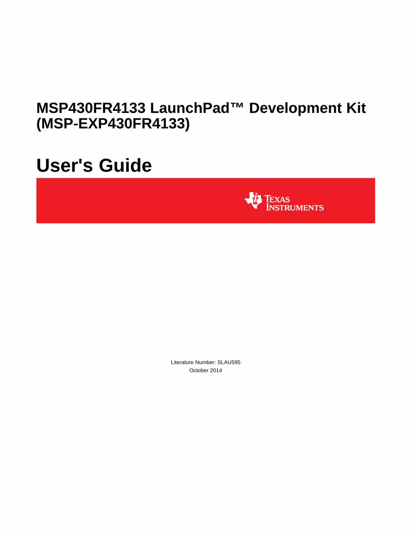
www.ti.com Hardware
Figure 4. MSP430FR4133 Pinout
9SLAU595–October 2014 MSP430FR4133 LaunchPad™ Development Kit (MSP‑EXP430FR4133)Submit Documentation Feedback
Copyright © 2014, Texas Instruments Incorporated

Hardware www.ti.com
2.2.2 eZ-FET Onboard Emulator With EnergyTrace™ TechnologyTo keep development easy and cost effective, TI's LaunchPad Development Kits integrate an onboardemulator, which eliminates the need for expensive programmers. The MSP-EXP430FR4133 has the eZ-FET emulator (see Figure 5), which is a simple and low-cost debugger that supports all MSP430 devicederivatives.
Figure 5. eZ-FET Emulator
The MSP-EXP430FR4133 LaunchPad features EnergyTrace technology but does not have support forEnergyTrace++™ technology. The EnergyTrace functionality varies across the MSP portfolio (seeTable 1).
Table 1. EnergyTrace Technology
Feature EnergyTrace™ Technology EnergyTrace++™ TechnologyCurrent Monitoring ✓ ✓CPU State ✓Peripheral and System State ✓
MSP430FR59xx andDevices Supported All MSP430 MCUs MSP430FR69xx MCUsDevelopment Tool Required MSP-FET or eZ-FET MSP-FET or eZ-FET
The eZ-FET also provides a "backchannel" UART-over-USB connection with the host, which can be veryuseful during debugging and for easy communication with a PC. The provided UART supports hardwareflow control (RTS and CTS), although by default these signals are not connected to the target.
The dotted line through J101 shown in Figure 5 divides the eZ-FET emulator from the target area. Thesignals that cross this line can be disconnected by jumpers on J101, the isolation jumper block. Moredetails on the isolation jumper block are in Section 2.2.3.
The eZ-FET hardware can be found in the schematics in Section 6 and in the accompanying hardwaredesign files (SLAR102). The software and more information about the debugger can be found on the eZ-FET lite wiki.
10 MSP430FR4133 LaunchPad™ Development Kit (MSP‑EXP430FR4133) SLAU595–October 2014Submit Documentation Feedback
Copyright © 2014, Texas Instruments Incorporated

www.ti.com Hardware
2.2.3 Emulator Connection: Isolation Jumper BlockThe isolation jumper block at jumper J101 allows the user to connect or disconnect signals that cross fromthe eZ-FET domain into the MSP430FR4133 target domain. This includes eZ-FET Spy-Bi-Wire signals,application UART signals, and 3.3-V and 5-V power (see Table 2 and Figure 6).
Reasons to open these connections:• To remove any and all influence from the eZ-FET emulator for high accuracy target power
measurements• To control 3-V and 5-V power flow between the eZ-FET and target domains• To expose the target MCU pins for other use than onboard debugging and application UART
communication• To expose the programming and UART interface of the eZ-FET so that it can be used for devices other
than the onboard MCU.
Table 2. Isolation Block Connections
Jumper DescriptionGND Ground5V 5-V VBUS from USB3V3 3.3-V rail, derived from VBUS by an LDO in the eZ-FET domain
Backchannel UART: Ready-To-Send, for hardware flow control. The target can use this to indicate whether itRTS >> is ready to receive data from the host PC. The arrows indicate the direction of the signal.Backchannel UART: Clear-To-Send, for hardware flow control. The host PC (through the emulator) uses thisCTS << to indicate whether it is ready to receive data. The arrows indicate the direction of the signal.Backchannel UART: The target FR4133 receives data through this signal. The arrows indicate the directionRXD << of the signal.Backchannel UART: The target FR4133 sends data through this signal. The arrows indicate the direction ofTXD >> the signal.
SBW RST Spy-Bi-Wire emulation: SBWTDIO data signal. This pin also functions as the RST signal (active low).SBW TST Spy-Bi-Wire emulation: SBWTCK clock signal. This pin also functions as the TST signal.
11SLAU595–October 2014 MSP430FR4133 LaunchPad™ Development Kit (MSP‑EXP430FR4133)Submit Documentation Feedback
Copyright © 2014, Texas Instruments Incorporated

eZ-FET
Emulator
MCU
Isolation
Jumper Block
Sp
y-B
i-W
ire
(S
BW
)
Em
ula
tio
n
Ap
pli
cati
on
UA
RT
3.3
V P
ow
er
5V
Po
we
r
Target MSP430
MCU
eZ
-FE
TM
SP
43
0 T
arg
et
USB Connector
in out
LDO
Bo
ost
erP
ack
He
ad
er
Bo
ost
erP
ack
He
ad
er
USB
EnergyTrace
Hardware www.ti.com
Figure 6. eZ-FET Isolation Jumper Block Diagram
2.2.4 Application (or "Backchannel") UARTThe backchannel UART allows communication with the USB host that is not part of the target application'smain functionality. This is useful during development and also provides a communication channel to thePC host side. This can be used to create graphical user interfaces (GUIs) and other programs on the PCthat communicate with the LaunchPad.
The pathway of the backchannel UART is shown in Figure 6. The backchannel UART is the UART oneUSCI_A0. Because of USCI limitations, this UART channel is shared with the UART on the 20-pinBoosterPack connector (eUSCI_A0). This UART channel is also shared with the red LED on P1.0. This isa lot of sharing, but all 64 pins of the device are used and this was done out of necessity. The P1.0 pinserves more functions than any other.
On the host side, a virtual COM port for the application backchannel UART is generated when theLaunchPad enumerates on the host. You can use any PC application that interfaces with COM ports,including terminal applications like Hyperterminal or Docklight, to open this port and communicate with thetarget application. You need to identify the COM port for the backchannel. On Windows PCs, DeviceManager can assist (see Figure 7).
Figure 7. Application Backchannel UART in Device Manager
12 MSP430FR4133 LaunchPad™ Development Kit (MSP‑EXP430FR4133) SLAU595–October 2014Submit Documentation Feedback
Copyright © 2014, Texas Instruments Incorporated
www.ti.com Hardware
The backchannel UART is the "MSP Application UART1" port. In this case, Figure 7 shows COM13, butthis port can vary from one host PC to the next. After you identify the correct COM port, configure it inyour host application according to its documentation. You can then open the port and begincommunication to it from the host.
On the target MSP430FR4133 side, the backchannel is connected to the eUSCI_A0 module. The eZ-FEThas a configurable baud rate; therefore, it is important that the PC application configures the baud rate tobe the same as what is configured on the eUSCI_A0.
The eZ-FET also supports hardware flow control, if desired. Hardware flow control (CTS and RTShandshaking) allows the target MSP430FR4133 and the emulator to tell each other to wait before sendingmore data. At low baud rates and with simple target applications, flow control may not be necessary.Applications with higher baud rates and more interrupts to service have a higher likelihood that the will notbe able to read the eUSCI_A0 RXBUF register in time, before the next byte arrives. If this happens, theeUSCI_A0 UCA0STATW register reports an overrun error.
2.2.5 Special Features
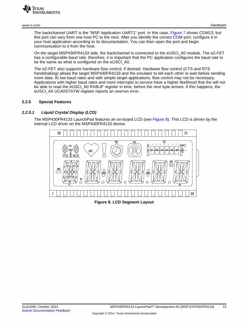
2.2.5.1 Liquid Crystal Display (LCD)The MSP430FR4133 LaunchPad features an on-board LCD (see Figure 8). This LCD is driven by theinternal LCD driver on the MSP430FR4133 device.
Figure 8. LCD Segment Layout
13SLAU595–October 2014 MSP430FR4133 LaunchPad™ Development Kit (MSP‑EXP430FR4133)Submit Documentation Feedback
Copyright © 2014, Texas Instruments Incorporated

Hardware www.ti.com
There are many available LCD segments, including six full alpha-numeric numbers and letters in additionto several symbols at the top for various modes or applications. Table 3 shows the mapping of thesesegments.
Table 3. LCD FH-1138P Segment Mapping
Pin COM3 COM2 COM1 COM01 A1E A1F A1G A1M2 A1A A1B A1C A1D3 A1Q NEG A1N A1DP4 A1H A1J A1K A1P5 A2E A2F A2G A2M6 A2A A2B A2C A2D7 A2Q A2COL A2N A2DP8 A2H A2J A2K A2P9 A3R A3F A3G A3M10 A3A A3B A3C A3D11 A3Q ANT A3N A3DP12 A3H A3J A3K A3P13 A4R A4F A4G A4M14 A4A A4B A4C A4D15 A4Q A4COL A4N A4DP16 A4H A4J A4K A4P17 A5E A5F A5G A5M18 A5A A5B A5C A5D19 A5Q DEG A5N A5DP20 A5H A5J A5K A5P21 COM3 - - -22 - COM2 - -23 - - COM1 -24 - - - COM025 - - - -26 - - - -27 - - - -28 - - - -29 - - - -30 - - - -31 - - - -32 TMR HRT REC !33 B6 B4 B2 BATT34 B5 B3 B1 []35 A6E A6F A6G A6M36 A6A A6B A6C A6D37 A6Q TX A6N RX38 A6H A6J A6K A6P
14 MSP430FR4133 LaunchPad™ Development Kit (MSP‑EXP430FR4133) SLAU595–October 2014Submit Documentation Feedback
Copyright © 2014, Texas Instruments Incorporated

www.ti.com Hardware
The MSP430FR4133 device has flexible LCD pins allowing any pin to be a SEG or a COM. This simplifieslayout for the user. The LCD connections are typically a tradeoff between easy layout and optimal memorysettings for cleaner user software, among other considerations. The flexibility of the MSP430FR4133allowed an optimal memory setting for easy software, along with a simple layout on the PCB (seeTable 4).
Each LCDMEM register is eight bits, controlling up to eight segments. The FH-1138P is a 4-mux LCD, sofour COM pins are needed from the MSP430FR4133. With four COM pins, each segment pin controls fourbits or segments. This means that each LCDMEM register controls two segment pins, as shown inTable 4. Note that LCDMEM14 to LCDMEM17 and LCDMEM20 and higher are not used due to layoutconsiderations.
Each alphanumeric character A1 to A6 is controlled by two adjacent LCDMEM registers for efficiency andease of use in software. This allows for a single 16-bit memory access to control the whole character, asopposed to split memory regions requiring separate memory accesses.
Table 4. LCD to MSP430 ConnectionsC
OM
3
CO
M2
CO
M1
CO
M0
CO
M3
CO
M2
CO
M1
CO
M0
Port
Pin
Port
Pin
LCD
Pin
LCD
Pin
LCD
MEM
FR41
33Pi
n
FR41
33Pi
n
LCDM19 P5.7 L39 38 A6H A6J A6K A6P P5.6 L38 37 A6Q TX A6N RX
LCDM18 P5.5 L37 36 A6A A6B A6C A6D P5.4 L36 35 A6E A6F A6G A6M
LCDM17 P5.3 L35 P5.2 L34
LCDM16 P5.1 L33 P5.0 L32
LCDM15 P2.7 L31 P2.6 L30
LCDM14 P2.5 L29 P2.4 L28
LCDM13 P2.3 L27 P2.2 L26 34 B5 B3 B1 []
LCDM12 P2.1 L25 33 B6 B4 B2 BATT P2.0 L24 32 TMR HRT REC !
LCDM11 P6.7 L23 16 A4H A4J A4K A4P P6.6 L22 15 A4Q A4COL A4N A4DP
LCDM10 P6.5 L21 14 A4A A4B A4C A4D P6.4 L20 13 A4R A4F A4G A4M
LCDM9 P6.3 L19 12 A3H A3J A3K A3P P6.2 L18 11 A3Q ANT A3N A3DP
LCDM8 P6.1 L17 10 A3A A3B A3C A3D P6.0 L16 9 A3R A3F A3G A3M
LCDM7 P3.7 L15 8 A2H A2J A2K A2P P3.6 L14 7 A2Q A2COL A2N A2DP
LCDM6 P3.5 L13 6 A2A A2B A2C A2D P3.4 L12 5 A2E A2F A2G A2M
LCDM5 P3.3 L11 4 A1H A1J A1K A1P P3.2 L10 3 A1Q NEG A1N A1DP
LCDM4 P3.1 L9 2 A1A A1B A1C A1D P3.0 L8 1 A1E A1F A1G A1M
LCDM3 P7.7 L7 20 A5H A5J A5K A5P P7.6 L6 19 A5Q DEG A5N A5DP
LCDM2 P7.5 L5 18 A5A A5B A5C A5D P7.4 L4 17 A5E A5F A5G A5M
LCDM1 P7.3 L3 21 COM3 - - - P7.2 L2 22 - COM2 - -
LCDM0 P7.1 L1 23 - - COM1 - P7.0 L0 24 - - - COM0
15SLAU595–October 2014 MSP430FR4133 LaunchPad™ Development Kit (MSP‑EXP430FR4133)Submit Documentation Feedback
Copyright © 2014, Texas Instruments Incorporated

Debug
Power
Domain
Target and
BoosterPack
Power
Domain
LegendJ101
3V
3
eZ-FET
J1 J2
MSP430FR4133
target and
BoosterPack
VCC
GND
GND
J6
Target
MSP430FR4133
Device
LCD
USB (eZ-FET) Power
Configuration
Pla
ce
Ju
mp
er
BoosterPack and External
Power Configuration
J101
3V
3
eZ-FET
J1 J2
MSP430FR4133
target and
BoosterPack
VCC
GND
GND
J6
Target
MSP430FR4133
Device
LCD
No
Ju
mp
er
Hardware www.ti.com
2.3 PowerThe board was designed to accommodate various powering methods, including through the on-board eZ-FET and from external or BoosterPack power (see Figure 9).
Figure 9. MSP-EXP430FR4133 Power Block Diagram
2.3.1 eZ-FET USB PowerThe most common power-supply scenario is from USB through the eZ-FET debugger. This provides 5-Vpower from the USB and also regulates this power rail to 3.3 V for eZ-FET operation and 3.3 V to thetarget side of the LaunchPad. Power from the eZ-FET is controlled by jumper J101. For 3.3 V, make surethat a jumper is connected across the J101 3V3 terminal.
2.3.2 BoosterPack and External Power SupplyHeader J6 is present on the board to supply external power directly. It is important to comply with thedevice voltage operation specifications when supplying external power. The MSP430FR4133 has anoperating range of 1.8 V to 3.6 V. More information can be found in the MSP430FR4133 data sheet(SLAS865).
16 MSP430FR4133 LaunchPad™ Development Kit (MSP‑EXP430FR4133) SLAU595–October 2014Submit Documentation Feedback
Copyright © 2014, Texas Instruments Incorporated
www.ti.com Hardware
2.4 Measure MSP430 Current DrawTo measure the current draw of the MSP430FR4133 using a multi-meter, use the 3V3 jumper on thejumper isolation block. The current measured includes the target device and any current drawn throughthe BoosterPack headers.
To measure ultra-low power, follow these steps:1. Remove the 3V3 jumper in the isolation block, and attach an ammeter across this jumper.2. Consider the effect that the backchannel UART and any circuitry attached to the MSP430FR4133 may
have on current draw. Consider disconnecting these at the isolation jumper block, or at least considertheir current sinking and sourcing capability in the final measurement.
3. Make sure there are no floating input/output (I/Os). These cause unnecessary extra current draw.Every I/O should either be driven out or, if it is an input, should be pulled or driven to a high or lowlevel.
4. Begin target execution.5. Measure the current. Keep in mind that if the current levels are fluctuating, it may be difficult to get a
stable measurement. It is easier to measure quiescent states.
Alternatively, EnergyTrace technology can be used to measure the same current, and see energy profilesthrough integrated GUI in CCS and IAR. EnergyTrace allows you to compare various current profiles andbetter optimize your energy performance!
2.5 ClockingThe MSP-EXP430FR4133 provides an external clock in addition to the internal clocks in the device.• Y1: a 32-kHz crystal
The 32-kHz crystal allows for lower LPM3 sleep currents than do the other low-frequency clock sources.Therefore, the presence of the crystal allows the full range of low-power modes to be used.
The internal clocks in the device default to the following configuration:• MCLK: DCO, 2 MHz• SMCLK: DCO, 2 MHz• ACLK: REFO, 32.768 kHz
For more information about configuring internal clocks and using the external oscillators, see theMSP430FR4xx and MSP430FR2xx Family User's Guide (SLAU445).
2.6 Using the eZ-FET Emulator With a Different TargetThe eZ-FET emulator on the LaunchPad can interface to most MSP430 derivative devices, not just the on-board MSP430FR4133 target device.
To do this, disconnect every jumper in the isolation jumper block. This is necessary, because the emulatorcannot connect to more than one target at a time over the Spy-Bi-Wire (SBW) connection.
Next, make sure the target board has proper connections for SBW. Note that to be compatible with SBW,the capacitor on RST/SBWTDIO cannot be greater than 2.2 nF. The documentation for designing MSP430JTAG interface circuitry is the MSP430 Hardware Tools User's Guide (SLAU278).
Finally, wire together these signals from the emulator side of the isolation jumper block to the targethardware:
• 5 V (if 5 V is needed) • TXD (if the UART backchannel is used)• 3.3 V • RXD (if the UART backchannel is used)• GND • CTS (if hardware flow control is used)• SBWTDIO • RTS (if hardware flow control is used)• SBWTCKThis wiring can be done either with jumper wires or by designing the board with a connector that plugsinto the isolation jumper block.
17SLAU595–October 2014 MSP430FR4133 LaunchPad™ Development Kit (MSP‑EXP430FR4133)Submit Documentation Feedback
Copyright © 2014, Texas Instruments Incorporated
The following pins are exposed at the BoosterPack connector.
+3.3V
P8.1
P2.7
P1.1
P8.0
P5.1
P2.5
P8.2
P8.3
P1.0UART
RX
TX
Analog In
Analog In
SPI CLK
I2C*SCL
SDA
A9
A1UCA0RXDUCA0SOMI
A0UCA0TXDUCA0SIMO
L31
SMCLK A8
L33UCB0CLK
L29
TA1CLK
TA1.2
BoosterPack
StandardMSP-EXP430FR4133 Pin Map
+3.3V
GPIO (!)
GPIO (!)
(!)
(!)
(!)
(!)
AC LK
GND
P1.7
P1.6
RST
P5.2
P1.3
P1.4
P1.5
P5.3
A7TA0.1 TDO
L34 UCB0SDA
L35 UCB0SCLUCB0SOMI
A4MCLK TCK
A5TMS TA0CLK
A6TA0.2 TDI TCLK
A3
UCB0STE
UCB0SIMOSPI
MOSI
MISO
SPI CS Wireless
SPI CS Display
SPI CS Other
BoosterPack StandardMSP-EXP430FR4133 Pin Map
GND
RST
PWM Out GPIO (!)
GPIO (!)
GPIO (!)
GPIO (!)
GPIO (!)
(!)
(!)
(!)
(!)
(!)
UCA0STE
P5.0 L32 GPIO**
Also shown are functions that map with the BoosterPack standard.* Note that to comply with the I C channels of the BoosterPack standard, a software-emulated I C must be used.** Some LaunchPads do not 100% comply with the standard, please check your LaunchPad to ensure compatability(!) Denotes I/O pins that are interrupt-capable.
2 2
Hardware www.ti.com
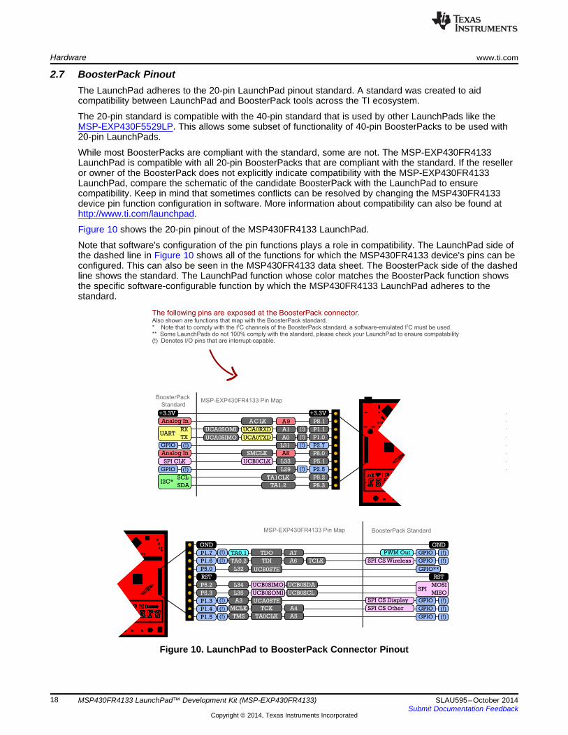
2.7 BoosterPack PinoutThe LaunchPad adheres to the 20-pin LaunchPad pinout standard. A standard was created to aidcompatibility between LaunchPad and BoosterPack tools across the TI ecosystem.
The 20-pin standard is compatible with the 40-pin standard that is used by other LaunchPads like theMSP‑EXP430F5529LP. This allows some subset of functionality of 40-pin BoosterPacks to be used with20-pin LaunchPads.
While most BoosterPacks are compliant with the standard, some are not. The MSP-EXP430FR4133LaunchPad is compatible with all 20-pin BoosterPacks that are compliant with the standard. If the reselleror owner of the BoosterPack does not explicitly indicate compatibility with the MSP-EXP430FR4133LaunchPad, compare the schematic of the candidate BoosterPack with the LaunchPad to ensurecompatibility. Keep in mind that sometimes conflicts can be resolved by changing the MSP430FR4133device pin function configuration in software. More information about compatibility can also be found athttp://www.ti.com/launchpad.
Figure 10 shows the 20-pin pinout of the MSP430FR4133 LaunchPad.
Note that software's configuration of the pin functions plays a role in compatibility. The LaunchPad side ofthe dashed line in Figure 10 shows all of the functions for which the MSP430FR4133 device's pins can beconfigured. This can also be seen in the MSP430FR4133 data sheet. The BoosterPack side of the dashedline shows the standard. The LaunchPad function whose color matches the BoosterPack function showsthe specific software-configurable function by which the MSP430FR4133 LaunchPad adheres to thestandard.
Figure 10. LaunchPad to BoosterPack Connector Pinout
18 MSP430FR4133 LaunchPad™ Development Kit (MSP‑EXP430FR4133) SLAU595–October 2014Submit Documentation Feedback
Copyright © 2014, Texas Instruments Incorporated
www.ti.com Hardware
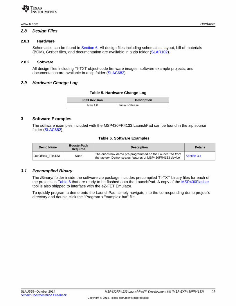
2.8 Design Files
2.8.1 HardwareSchematics can be found in Section 6. All design files including schematics, layout, bill of materials(BOM), Gerber files, and documentation are available in a zip folder (SLAR102).
2.8.2 SoftwareAll design files including TI-TXT object-code firmware images, software example projects, anddocumentation are available in a zip folder (SLAC682).
2.9 Hardware Change Log
Table 5. Hardware Change Log
PCB Revision DescriptionRev 1.0 Initial Release
3 Software ExamplesThe software examples included with the MSP430FR4133 LaunchPad can be found in the zip sourcefolder (SLAC682).
Table 6. Software Examples
BoosterPackDemo Name Description DetailsRequiredThe out-of-box demo pre-programmed on the LaunchPad fromOutOfBox_FR4133 None Section 3.4the factory. Demonstrates features of MSP430FR4133 device
3.1 Precompiled BinaryThe /Binary/ folder inside the software zip package includes precompiled TI-TXT binary files for each ofthe projects in Table 6 that are ready to be flashed onto the LaunchPad. A copy of the MSP430Flashertool is also shipped to interface with the eZ-FET Emulator.
To quickly program a demo onto the LaunchPad, simply navigate into the corresponding demo project'sdirectory and double click the "Program <Example>.bat" file.
19SLAU595–October 2014 MSP430FR4133 LaunchPad™ Development Kit (MSP‑EXP430FR4133)Submit Documentation Feedback
Copyright © 2014, Texas Instruments Incorporated

Software Examples www.ti.com
Figure 11. Programming the LaunchPad With Program Batch Files
If desired, the "Program <Example>.bat" file can be modified to point to your own projects' binary file.
NOTE: After importing and compiling the software source code in an IDE such as CCS or IAR, theTI-TXT binary files located in the /Binary/ folder are not updated automatically. Copy thenewly compiled binary from your IDE's /Workspace/Project/ directory and replace the"<Example>.txt" in /Binary/ for the batch file to program your own binary file.
3.2 MSP430Ware LibraryThe examples are built upon MSP430 libraries shown below that are available from TI. All libraries areavailable as part of MSP430Ware. Downloading CCS includes MSP430Ware along with TI ResourceExplorer.• Driver library (MSP430DRIVERLIB): a foundational MSP430 software library that is useful for
interfacing with all MSP430 core functions and peripherals, especially clocks and power.• Graphics library (MSP430-GRLIB): a library for interfacing MSP430 devices to dot-matrix LCD displays.
Contains primitives for simple drawing as well as images and more.• Capacitive Touch Library (CAPSENSELIBRARY): a library for capacitive touch sensing applications.
This library supports the use of buttons, sliders, wheels and more. Highly configurable for eachapplication.
When you begin your own development, you will need more information about these libraries than can beincluded in this user's guide. All of the information that you need is in MSP430Ware or the specific librarydocumentation linked above.
3.3 Development Environment RequirementsTo use any of the software examples with the LaunchPad, you must have an IDE that supports theMSP430FR4133 device (see Table 7). For more details on where to download the latest IDE, seeSection 4.3.
Table 7. IDE Minimum Requirements for MSP-EXP430FR4133
Code Composer Studio™ IDE IAR Embedded Workbench™ IDECCS v6.0 or later IAR EW430 v6.10 or later
20 MSP430FR4133 LaunchPad™ Development Kit (MSP‑EXP430FR4133) SLAU595–October 2014Submit Documentation Feedback
Copyright © 2014, Texas Instruments Incorporated

www.ti.com Software Examples
3.3.1 CCSCCS v6.0 or later is required. When CCS has been launched, and a workspace directory chosen, useProject>Import Existing CCS Eclipse Project. Direct it to the desired demo project directory that containsmain.c (see Figure 12). Selecting the \CCS subdirectory also works. The CCS-specific files are locatedthere.
Figure 12. Directing the Project>Import Function to the Demo Project
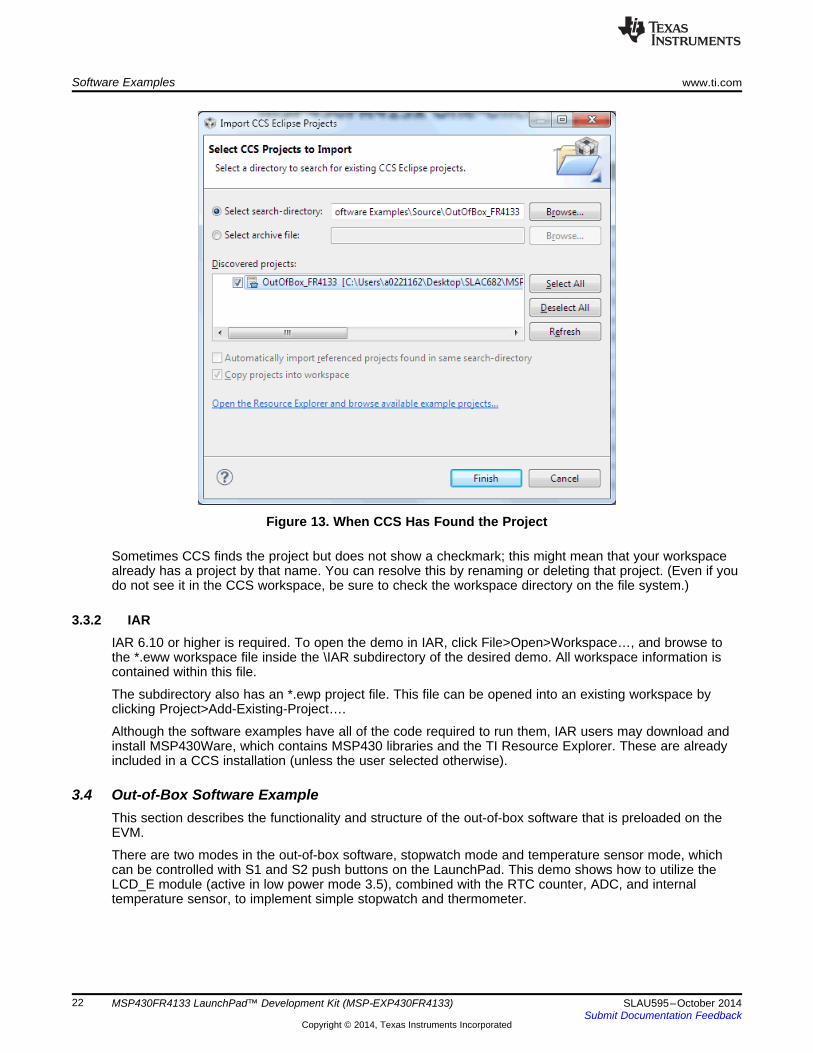
When you click OK, CCS should recognize the project and allow you to import it. The indication that CCShas found the project is that it appears in "Discovered projects" and is checked (see Figure 13).
21SLAU595–October 2014 MSP430FR4133 LaunchPad™ Development Kit (MSP‑EXP430FR4133)Submit Documentation Feedback
Copyright © 2014, Texas Instruments Incorporated
Software Examples www.ti.com
Figure 13. When CCS Has Found the Project
Sometimes CCS finds the project but does not show a checkmark; this might mean that your workspacealready has a project by that name. You can resolve this by renaming or deleting that project. (Even if youdo not see it in the CCS workspace, be sure to check the workspace directory on the file system.)
3.3.2 IARIAR 6.10 or higher is required. To open the demo in IAR, click File>Open>Workspace…, and browse tothe *.eww workspace file inside the \IAR subdirectory of the desired demo. All workspace information iscontained within this file.
The subdirectory also has an *.ewp project file. This file can be opened into an existing workspace byclicking Project>Add-Existing-Project….
Although the software examples have all of the code required to run them, IAR users may download andinstall MSP430Ware, which contains MSP430 libraries and the TI Resource Explorer. These are alreadyincluded in a CCS installation (unless the user selected otherwise).
3.4 Out-of-Box Software ExampleThis section describes the functionality and structure of the out-of-box software that is preloaded on theEVM.
There are two modes in the out-of-box software, stopwatch mode and temperature sensor mode, whichcan be controlled with S1 and S2 push buttons on the LaunchPad. This demo shows how to utilize theLCD_E module (active in low power mode 3.5), combined with the RTC counter, ADC, and internaltemperature sensor, to implement simple stopwatch and thermometer.
22 MSP430FR4133 LaunchPad™ Development Kit (MSP‑EXP430FR4133) SLAU595–October 2014Submit Documentation Feedback
Copyright © 2014, Texas Instruments Incorporated

www.ti.com Software Examples
3.4.1 Source File StructureThe project is split into multiple files. This makes it easier to navigate and reuse parts of it for otherprojects.
Table 8. List of Source Files and Folders
Name Descriptionmain.c The out-of-box demo main function, initializations, shared ISRs, and so onhal_LCD.c Hardware abstraction layer for LCDStopWatchMode.c Main function file for stopwatch modeTempSensorMode.c Main function file for live thermometer modeLibrary: Driverlib Device driver library (MSP430DRIVERLIB)
3.4.2 Power Up and IdleUpon powering up the out-of-box demo, the LCD displays a scrolling welcome message. TheMSP430FR4133 then enters a loop, in which the LCD cycles through all of its segments followed by ascrolling instruction message to "Hold S1 and S2 to switch modes".
3.4.3 Stopwatch ModeWhile in the power up and idle state or in the temperature sensor mode, the stopwatch mode can beentered by holding down both S1 and S2 buttons shortly. The LCD displays scrolling text "STOPWATCHMODE" to indicate successful entry into this mode.
The MSP430FR4133 initializes the stopwatch calendar to HH:MM:SS:CC = 00:00:00:00, then goes tosleep in LPM3.5. Since the onboard LCD has 6 alphanumeric digits, the stopwatch format is initiallyMM:SS:CC but becomes HH:MM:SS when the timer reaches the first hour.
Press the S1 button to start the stopwatch timer (counts up). While the timer is running, theMSP430FR4133 sleeps and wakes between LPM3 (waiting for RTC interrupt) and active mode(incrementing calendar and updating LCD). Press the S1 button again to stop the stopwatch timer andreturn the MSP430FR4133 back to LPM3.5 to conserve power. When the stopwatch timer is stopped,press the S2 button resets the timer back to 00:00:00.
While the stopwatch timer is running, press the S2 button to pause the LCD at the current time butcontinue the timer running in the background, allowing for the "split timer" functionality. Press the S2button to resume display of the running timer on the LCD.
3.4.4 Temperature Sensor ModeWhile in the stopwatch mode, the temperature sensor mode can be entered by holding down both S1 andS2 buttons shortly. The LCD displays scrolling text "TEMPSENSOR MODE" to indicate successful entryinto this mode.
Upon entering this mode, the MSP430FR4133 initializes the ADC input to its internal temperature sensorand starts sampling/conversion at four times per second. Each time an ADC conversion completes, theLCD shows the calculated temperature to the tenths decimal place.
The temperature unit can be toggled between Celsius and Fahrenheit by pressing the S2 button.
The temperature measurement can also be paused/resumed by pressing the S1 button. While thetemperature measurement is running, the MSP430FR4133 sleeps and wakes between LPM3 (waiting forADC sample/conversion to finish) and active mode (processing the results and updating LCD). When thetemperature measurement is paused, the MSP430FR4133 enters LPM3.5 with the LCD remaining ondisplaying the last measured temperature.
23SLAU595–October 2014 MSP430FR4133 LaunchPad™ Development Kit (MSP‑EXP430FR4133)Submit Documentation Feedback
Copyright © 2014, Texas Instruments Incorporated
Additional Resources www.ti.com
4 Additional Resources
4.1 LaunchPad WebsitesMore information about the MSP430FR4133 LaunchPad, supported BoosterPacks, and availableresources can be found at:• Tool Folder: resources specific to this particular LaunchPad• TI's LaunchPad portal: information about all LaunchPads from TI for all MCUs
4.2 Information on the MSP430FR4133At some point, you will probably want more information about the MSP430FR4133 device. For everyMSP430 device, the documentation is organized as shown in Table 9.
Table 9. How MSP430 Device Documentation is Organized
Document For MSP430FR4133 DescriptionMSP430FR4xx and MSP430FR2xx Architectural information about the device, including all modulesDevice family user's guide Family User's Guide (SLAU445) and peripherals such as clocks, timers, ADC, and so on.MSP430FR413x Mixed-Signal Device-specific information and all parametric information for thisDevice-specific data sheet Microcontrollers data sheet device(SLAS865)
4.3 Download CCS or IARAlthough the files can be viewed with any text editor, more can be done with the projects if they're openedwith a development environment like Code Composer Studio (CCS) or IAR Embedded Workbench.
CCS and IAR are available in full, free code-size, or time limited versions. The full out-of-box demo can bebuilt with the free versions of CCS and IAR (IAR KickStart), because it is under the code size limit. For fullfunctionality, download the full version of either CCS or IAR.
Go to the MSP430 software tools page to download them and for instructions on installation.
4.4 MSP430Ware and TI Resource ExplorerMSP430Ware is a complete collection of libraries and tools. It includes all of the MSP430 libraries used inthe software examples. By default, MSP430Ware is included in a CCS installation. IAR users mustdownload it separately.
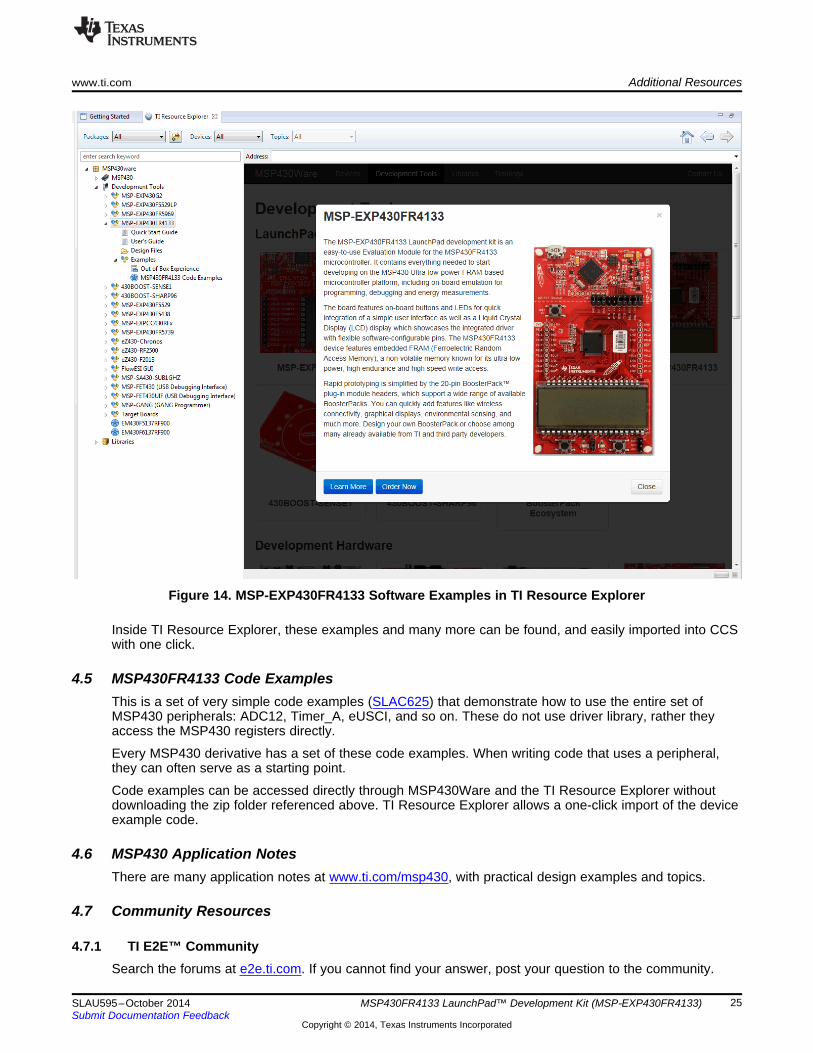
MSP430Ware is built into the TI Resource Explorer, for easily browsing tools. For example, all of thesoftware examples are shown in Figure 14.
24 MSP430FR4133 LaunchPad™ Development Kit (MSP‑EXP430FR4133) SLAU595–October 2014Submit Documentation Feedback
Copyright © 2014, Texas Instruments Incorporated
www.ti.com Additional Resources
Figure 14. MSP-EXP430FR4133 Software Examples in TI Resource Explorer
Inside TI Resource Explorer, these examples and many more can be found, and easily imported into CCSwith one click.
4.5 MSP430FR4133 Code ExamplesThis is a set of very simple code examples (SLAC625) that demonstrate how to use the entire set ofMSP430 peripherals: ADC12, Timer_A, eUSCI, and so on. These do not use driver library, rather theyaccess the MSP430 registers directly.
Every MSP430 derivative has a set of these code examples. When writing code that uses a peripheral,they can often serve as a starting point.
Code examples can be accessed directly through MSP430Ware and the TI Resource Explorer withoutdownloading the zip folder referenced above. TI Resource Explorer allows a one-click import of the deviceexample code.
4.6 MSP430 Application NotesThere are many application notes at www.ti.com/msp430, with practical design examples and topics.
4.7 Community Resources
4.7.1 TI E2E™ CommunitySearch the forums at e2e.ti.com. If you cannot find your answer, post your question to the community.
25SLAU595–October 2014 MSP430FR4133 LaunchPad™ Development Kit (MSP‑EXP430FR4133)Submit Documentation Feedback
Copyright © 2014, Texas Instruments Incorporated

FAQ www.ti.com
4.7.2 Community at LargeMany online communities focus on the LaunchPad – for example, http://www.43oh.com. You can findadditional tools, resources, and support from these communities.
5 FAQQ: I can't get the backchannel UART to connect. What's wrong?A: Check the following:• Do the baud rate in the host's terminal application and the USCI settings match?• Are the appropriate jumpers in place, on the isolation jumper block?• Probe on RXD and send data from the host. If you don't see data, it might be a problem on the host
side.• Probe on TXD while sending data from the MSP430. If you don't see data, it might be a configuration
problem with the eUSCI module.• Consider the use of the hardware flow control lines (especially for higher baud rates).
Q: So the onboard emulator is really open source? And I can build my own onboard emulator?A: Yes! We encourage you to do so. The design files are on ti.com.
Q: The MSP430 G2 LaunchPad had a socket, allowing me change the target device. Why doesn'tthis LaunchPad use one?A: This LaunchPad provides more functionality, and this means using a device with more pins. Sockets fordevices with this many pins are too expensive for the LaunchPad's target price.
Q: With the female headers on the bottom, the board doesn't sit flat on the table, and I can'tunsolder them. Why did TI do this?A: For several reasons. A major feedback item on previous LaunchPads was the desire for femaleheaders instead of male ones. But simply using female instead is problematic, because compatibility withexisting BoosterPacks would be lost, and some people prefer male headers. So, adding female headerswithout removing male ones satisfies both preferences. It also allows more flexibility in stackingBoosterPacks and other LaunchPads.
26 MSP430FR4133 LaunchPad™ Development Kit (MSP‑EXP430FR4133) SLAU595–October 2014Submit Documentation Feedback
Copyright © 2014, Texas Instruments Incorporated
A B C D
12
34
56
A B C D
12
34
56
www.ti.com Schematics
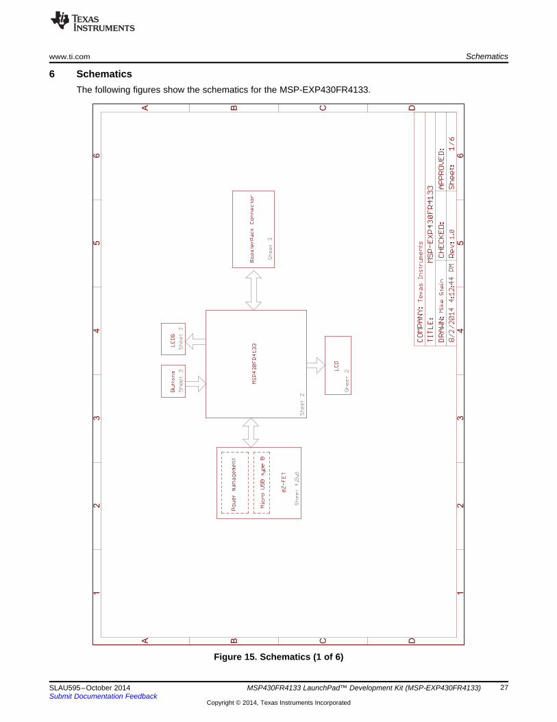
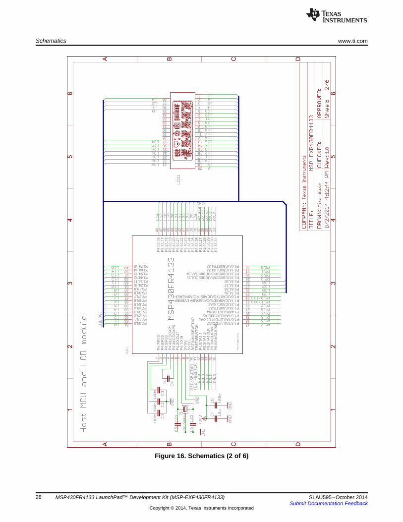
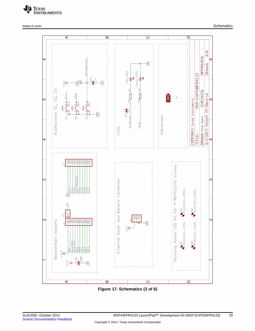
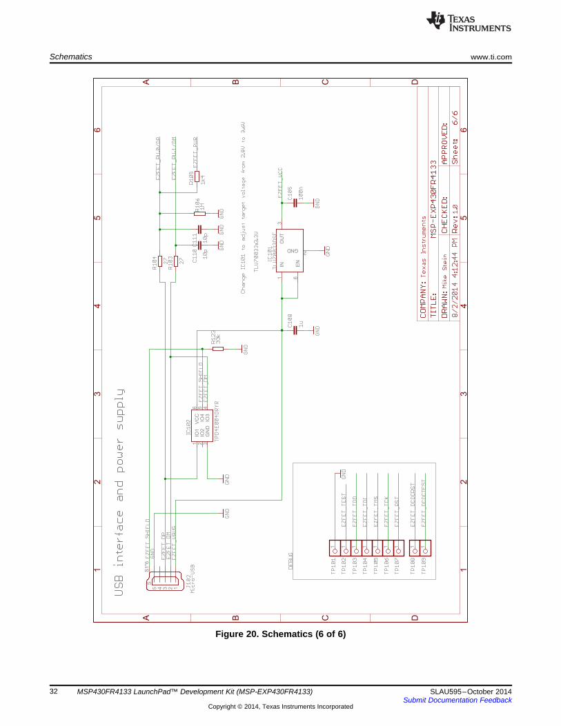
6 SchematicsThe following figures show the schematics for the MSP-EXP430FR4133.
Figure 15. Schematics (1 of 6)
27SLAU595–October 2014 MSP430FR4133 LaunchPad™ Development Kit (MSP‑EXP430FR4133)Submit Documentation Feedback
Copyright © 2014, Texas Instruments Incorporated
A B C D
12
34
56
A B C D
12
34
56
P4
.7/R
13
1
P4
.6/R
23
2
P4
.5/R
33
3
P4
.4/L
CD
CA
P1
4
P4
.3/L
CD
CA
P0
5
P4
.2/X
OU
T6
P4
.1/X
IN7
DV
SS
8
DV
CC
9
RS
T/N
MI/
SB
WT
DIO
10
TE
ST
/SB
WT
CK
11
P4
.0/T
A1
.11
2
P8
.3/T
A1
.21
3
P8
.2/T
A1
CL
K1
4
P8
.1/A
CL
K/A
91
5
P8
.0/S
MC
LK
/A8
16
P1.7/TA0.1/TDO/A717
P1.6/TA0.2/TDI/TCLK/A618
P1.5/TA0CLK/TMS/A519
P1.4/MCLK/TCK/A420
P1.3/UCA0STE/A321
P1.2/UCA0CLK/A222
P1.1/UCA0RXD/UCA0SOMI/A1/VEREF+23
P1.0/UCA0TXD/UCA0SIMO/A0/VEREF-24
P5.7/L3925
P5.6/L3826
P5.5/L3727
P5.4/L3628
P5.3/UCB0SOMI/UCB0SCL/L3529
P5.2/UCB0SIMO/UCB0SDA/L3430
P5.1/UCB0CLK/L3331
P5.0/UCB0STE/L3232
P2
.7/L
31
33
P2
.6/L
30
34
P2
.5/L
29
35
P2
.4/L
28
36
P2
.3/L
27
37
P2
.2/L
26
38
P2
.1/L
25
39
P2
.0/L
24
40
P6
.7/L
23
41
P6
.6/L
22
42
P6
.5/L
21
43
P6
.4/L
20
44
P6
.3/L
19
45
P6
.2/L
18
46
P6
.1/L
17
47
P6
.0/L
16
48
P3.7/L1549
P3.6/L1450
P3.5/L1351
P3.4/L1252
P3.3/L1153
P3.2/L1054
P3.1/L955
P3.0/L856
P7.7/L757
P7.6/L658
P7.5/L559
P7.4/L460
P7.3/L361
P7.2/L262
P7.1/L163
P7.0/L064
1
2
3
4
5
6
7
8
9
10
11
12
13
14
15
16
17
18
19
20
21
22
23
24
25
26
27
28
29
30
31
32
33
34
35
36
37
38
Schematics www.ti.com
Figure 16. Schematics (2 of 6)
28 MSP430FR4133 LaunchPad™ Development Kit (MSP‑EXP430FR4133) SLAU595–October 2014Submit Documentation Feedback
Copyright © 2014, Texas Instruments Incorporated
A B C D
12
34
56
A B C D
12
34
56
1 2 3
1 2 3 4 5 6 7 8 9
10
1 2 3 4 5 6 7 8 9
10
13 4
2 13 4
2 1
2
11
3 42
www.ti.com Schematics
Figure 17. Schematics (3 of 6)
29SLAU595–October 2014 MSP430FR4133 LaunchPad™ Development Kit (MSP‑EXP430FR4133)Submit Documentation Feedback
Copyright © 2014, Texas Instruments Incorporated

A B C D
12
34
56
A B C D
12
34
56
1 2 3 4 5 6 71
0
11
12
13
14
15
16
89T
P
NO
11
IN1
3
NO
25
IN2
7
CO
M1
8
CO
M2
4
V+2
GND6
Schematics www.ti.com
Figure 18. Schematics (4 of 6)
30 MSP430FR4133 LaunchPad™ Development Kit (MSP‑EXP430FR4133) SLAU595–October 2014Submit Documentation Feedback
Copyright © 2014, Texas Instruments Incorporated

A B C D
12
34
56
A B C D
12
34
56
64
63
62
61
60
59
58
57
56
55
54
53
52
51
50
49
48
47
46
45
44
43
42
41
40
39
38
37
36
35
34
33
32
31
30
29
28
27
26
25
24
23
22
21
20
19
18
17
161 2 3 4 5 6 7 8 9
11
12
13
14
15
10
TP
12
34
56
78
91
0
11
12
13
14
15
16
17
18
19
20
1
2
3
www.ti.com Schematics
Figure 19. Schematics (5 of 6)
31SLAU595–October 2014 MSP430FR4133 LaunchPad™ Development Kit (MSP‑EXP430FR4133)Submit Documentation Feedback
Copyright © 2014, Texas Instruments Incorporated
A B C D
12
34
56
A B C D
12
34
56
IO1
1
IO2
2
GN
D3
IO3
4IO
45
VC
C6
1 11 1 1 1 111
12345
SS
1*6
IN1
EN
6
OU
T3
GND2
Schematics www.ti.com
Figure 20. Schematics (6 of 6)
32 MSP430FR4133 LaunchPad™ Development Kit (MSP‑EXP430FR4133) SLAU595–October 2014Submit Documentation Feedback
Copyright © 2014, Texas Instruments Incorporated

STANDARD TERMS AND CONDITIONS FOR EVALUATION MODULES1. Delivery: TI delivers TI evaluation boards, kits, or modules, including any accompanying demonstration software, components, or
documentation (collectively, an “EVM” or “EVMs”) to the User (“User”) in accordance with the terms and conditions set forth herein.Acceptance of the EVM is expressly subject to the following terms and conditions.1.1 EVMs are intended solely for product or software developers for use in a research and development setting to facilitate feasibility
evaluation, experimentation, or scientific analysis of TI semiconductors products. EVMs have no direct function and are notfinished products. EVMs shall not be directly or indirectly assembled as a part or subassembly in any finished product. Forclarification, any software or software tools provided with the EVM (“Software”) shall not be subject to the terms and conditionsset forth herein but rather shall be subject to the applicable terms and conditions that accompany such Software
1.2 EVMs are not intended for consumer or household use. EVMs may not be sold, sublicensed, leased, rented, loaned, assigned,or otherwise distributed for commercial purposes by Users, in whole or in part, or used in any finished product or productionsystem.
2 Limited Warranty and Related Remedies/Disclaimers:2.1 These terms and conditions do not apply to Software. The warranty, if any, for Software is covered in the applicable Software
License Agreement.2.2 TI warrants that the TI EVM will conform to TI's published specifications for ninety (90) days after the date TI delivers such EVM
to User. Notwithstanding the foregoing, TI shall not be liable for any defects that are caused by neglect, misuse or mistreatmentby an entity other than TI, including improper installation or testing, or for any EVMs that have been altered or modified in anyway by an entity other than TI. Moreover, TI shall not be liable for any defects that result from User's design, specifications orinstructions for such EVMs. Testing and other quality control techniques are used to the extent TI deems necessary or asmandated by government requirements. TI does not test all parameters of each EVM.
2.3 If any EVM fails to conform to the warranty set forth above, TI's sole liability shall be at its option to repair or replace such EVM,or credit User's account for such EVM. TI's liability under this warranty shall be limited to EVMs that are returned during thewarranty period to the address designated by TI and that are determined by TI not to conform to such warranty. If TI elects torepair or replace such EVM, TI shall have a reasonable time to repair such EVM or provide replacements. Repaired EVMs shallbe warranted for the remainder of the original warranty period. Replaced EVMs shall be warranted for a new full ninety (90) daywarranty period.
3 Regulatory Notices:3.1 United States
3.1.1 Notice applicable to EVMs not FCC-Approved:This kit is designed to allow product developers to evaluate electronic components, circuitry, or software associated with the kitto determine whether to incorporate such items in a finished product and software developers to write software applications foruse with the end product. This kit is not a finished product and when assembled may not be resold or otherwise marketed unlessall required FCC equipment authorizations are first obtained. Operation is subject to the condition that this product not causeharmful interference to licensed radio stations and that this product accept harmful interference. Unless the assembled kit isdesigned to operate under part 15, part 18 or part 95 of this chapter, the operator of the kit must operate under the authority ofan FCC license holder or must secure an experimental authorization under part 5 of this chapter.3.1.2 For EVMs annotated as FCC – FEDERAL COMMUNICATIONS COMMISSION Part 15 Compliant:
CAUTIONThis device complies with part 15 of the FCC Rules. Operation is subject to the following two conditions: (1) This device may notcause harmful interference, and (2) this device must accept any interference received, including interference that may causeundesired operation.Changes or modifications not expressly approved by the party responsible for compliance could void the user's authority tooperate the equipment.
FCC Interference Statement for Class A EVM devicesNOTE: This equipment has been tested and found to comply with the limits for a Class A digital device, pursuant to part 15 ofthe FCC Rules. These limits are designed to provide reasonable protection against harmful interference when the equipment isoperated in a commercial environment. This equipment generates, uses, and can radiate radio frequency energy and, if notinstalled and used in accordance with the instruction manual, may cause harmful interference to radio communications.Operation of this equipment in a residential area is likely to cause harmful interference in which case the user will be required tocorrect the interference at his own expense.
SPACER
SPACER
SPACER
SPACER
SPACER
SPACER
SPACER
SPACER

FCC Interference Statement for Class B EVM devicesNOTE: This equipment has been tested and found to comply with the limits for a Class B digital device, pursuant to part 15 ofthe FCC Rules. These limits are designed to provide reasonable protection against harmful interference in a residentialinstallation. This equipment generates, uses and can radiate radio frequency energy and, if not installed and used in accordancewith the instructions, may cause harmful interference to radio communications. However, there is no guarantee that interferencewill not occur in a particular installation. If this equipment does cause harmful interference to radio or television reception, whichcan be determined by turning the equipment off and on, the user is encouraged to try to correct the interference by one or moreof the following measures:
• Reorient or relocate the receiving antenna.• Increase the separation between the equipment and receiver.• Connect the equipment into an outlet on a circuit different from that to which the receiver is connected.• Consult the dealer or an experienced radio/TV technician for help.
3.2 Canada3.2.1 For EVMs issued with an Industry Canada Certificate of Conformance to RSS-210
Concerning EVMs Including Radio Transmitters:This device complies with Industry Canada license-exempt RSS standard(s). Operation is subject to the following two conditions:(1) this device may not cause interference, and (2) this device must accept any interference, including interference that maycause undesired operation of the device.
Concernant les EVMs avec appareils radio:Le présent appareil est conforme aux CNR d'Industrie Canada applicables aux appareils radio exempts de licence. L'exploitationest autorisée aux deux conditions suivantes: (1) l'appareil ne doit pas produire de brouillage, et (2) l'utilisateur de l'appareil doitaccepter tout brouillage radioélectrique subi, même si le brouillage est susceptible d'en compromettre le fonctionnement.
Concerning EVMs Including Detachable Antennas:Under Industry Canada regulations, this radio transmitter may only operate using an antenna of a type and maximum (or lesser)gain approved for the transmitter by Industry Canada. To reduce potential radio interference to other users, the antenna typeand its gain should be so chosen that the equivalent isotropically radiated power (e.i.r.p.) is not more than that necessary forsuccessful communication. This radio transmitter has been approved by Industry Canada to operate with the antenna typeslisted in the user guide with the maximum permissible gain and required antenna impedance for each antenna type indicated.Antenna types not included in this list, having a gain greater than the maximum gain indicated for that type, are strictly prohibitedfor use with this device.
Concernant les EVMs avec antennes détachablesConformément à la réglementation d'Industrie Canada, le présent émetteur radio peut fonctionner avec une antenne d'un type etd'un gain maximal (ou inférieur) approuvé pour l'émetteur par Industrie Canada. Dans le but de réduire les risques de brouillageradioélectrique à l'intention des autres utilisateurs, il faut choisir le type d'antenne et son gain de sorte que la puissance isotroperayonnée équivalente (p.i.r.e.) ne dépasse pas l'intensité nécessaire à l'établissement d'une communication satisfaisante. Leprésent émetteur radio a été approuvé par Industrie Canada pour fonctionner avec les types d'antenne énumérés dans lemanuel d’usage et ayant un gain admissible maximal et l'impédance requise pour chaque type d'antenne. Les types d'antennenon inclus dans cette liste, ou dont le gain est supérieur au gain maximal indiqué, sont strictement interdits pour l'exploitation del'émetteur
3.3 Japan3.3.1 Notice for EVMs delivered in Japan: Please see http://www.tij.co.jp/lsds/ti_ja/general/eStore/notice_01.page 日本国内に
輸入される評価用キット、ボードについては、次のところをご覧ください。http://www.tij.co.jp/lsds/ti_ja/general/eStore/notice_01.page
3.3.2 Notice for Users of EVMs Considered “Radio Frequency Products” in Japan: EVMs entering Japan are NOT certified byTI as conforming to Technical Regulations of Radio Law of Japan.
If User uses EVMs in Japan, User is required by Radio Law of Japan to follow the instructions below with respect to EVMs:1. Use EVMs in a shielded room or any other test facility as defined in the notification #173 issued by Ministry of Internal
Affairs and Communications on March 28, 2006, based on Sub-section 1.1 of Article 6 of the Ministry’s Rule forEnforcement of Radio Law of Japan,
2. Use EVMs only after User obtains the license of Test Radio Station as provided in Radio Law of Japan with respect toEVMs, or
3. Use of EVMs only after User obtains the Technical Regulations Conformity Certification as provided in Radio Law of Japanwith respect to EVMs. Also, do not transfer EVMs, unless User gives the same notice above to the transferee. Please notethat if User does not follow the instructions above, User will be subject to penalties of Radio Law of Japan.
SPACER
SPACER
SPACER
SPACER
SPACER
【無線電波を送信する製品の開発キットをお使いになる際の注意事項】本開発キットは技術基準適合証明を受けておりません。本製品のご使用に際しては、電波法遵守のため、以下のいずれかの措置を取っていただく必要がありますのでご注意ください。1. 電波法施行規則第6条第1項第1号に基づく平成18年3月28日総務省告示第173号で定められた電波暗室等の試験設備でご使用
いただく。2. 実験局の免許を取得後ご使用いただく。3. 技術基準適合証明を取得後ご使用いただく。
なお、本製品は、上記の「ご使用にあたっての注意」を譲渡先、移転先に通知しない限り、譲渡、移転できないものとします。上記を遵守頂けない場合は、電波法の罰則が適用される可能性があることをご留意ください。
日本テキサス・インスツルメンツ株式会社東京都新宿区西新宿6丁目24番1号西新宿三井ビル
3.3.3 Notice for EVMs for Power Line Communication: Please see http://www.tij.co.jp/lsds/ti_ja/general/eStore/notice_02.page電力線搬送波通信についての開発キットをお使いになる際の注意事項については、次のところをご覧ください。http://www.tij.co.jp/lsds/ti_ja/general/eStore/notice_02.page
SPACER4 EVM Use Restrictions and Warnings:
4.1 EVMS ARE NOT FOR USE IN FUNCTIONAL SAFETY AND/OR SAFETY CRITICAL EVALUATIONS, INCLUDING BUT NOTLIMITED TO EVALUATIONS OF LIFE SUPPORT APPLICATIONS.
4.2 User must read and apply the user guide and other available documentation provided by TI regarding the EVM prior to handlingor using the EVM, including without limitation any warning or restriction notices. The notices contain important safety informationrelated to, for example, temperatures and voltages.
4.3 Safety-Related Warnings and Restrictions:4.3.1 User shall operate the EVM within TI’s recommended specifications and environmental considerations stated in the user
guide, other available documentation provided by TI, and any other applicable requirements and employ reasonable andcustomary safeguards. Exceeding the specified performance ratings and specifications (including but not limited to inputand output voltage, current, power, and environmental ranges) for the EVM may cause personal injury or death, orproperty damage. If there are questions concerning performance ratings and specifications, User should contact a TIfield representative prior to connecting interface electronics including input power and intended loads. Any loads appliedoutside of the specified output range may also result in unintended and/or inaccurate operation and/or possiblepermanent damage to the EVM and/or interface electronics. Please consult the EVM user guide prior to connecting anyload to the EVM output. If there is uncertainty as to the load specification, please contact a TI field representative.During normal operation, even with the inputs and outputs kept within the specified allowable ranges, some circuitcomponents may have elevated case temperatures. These components include but are not limited to linear regulators,switching transistors, pass transistors, current sense resistors, and heat sinks, which can be identified using theinformation in the associated documentation. When working with the EVM, please be aware that the EVM may becomevery warm.
4.3.2 EVMs are intended solely for use by technically qualified, professional electronics experts who are familiar with thedangers and application risks associated with handling electrical mechanical components, systems, and subsystems.User assumes all responsibility and liability for proper and safe handling and use of the EVM by User or its employees,affiliates, contractors or designees. User assumes all responsibility and liability to ensure that any interfaces (electronicand/or mechanical) between the EVM and any human body are designed with suitable isolation and means to safelylimit accessible leakage currents to minimize the risk of electrical shock hazard. User assumes all responsibility andliability for any improper or unsafe handling or use of the EVM by User or its employees, affiliates, contractors ordesignees.
4.4 User assumes all responsibility and liability to determine whether the EVM is subject to any applicable international, federal,state, or local laws and regulations related to User’s handling and use of the EVM and, if applicable, User assumes allresponsibility and liability for compliance in all respects with such laws and regulations. User assumes all responsibility andliability for proper disposal and recycling of the EVM consistent with all applicable international, federal, state, and localrequirements.
5. Accuracy of Information: To the extent TI provides information on the availability and function of EVMs, TI attempts to be as accurateas possible. However, TI does not warrant the accuracy of EVM descriptions, EVM availability or other information on its websites asaccurate, complete, reliable, current, or error-free.
SPACER
SPACER
SPACER
SPACER
SPACER
SPACER

SPACER6. Disclaimers:
6.1 EXCEPT AS SET FORTH ABOVE, EVMS AND ANY WRITTEN DESIGN MATERIALS PROVIDED WITH THE EVM (AND THEDESIGN OF THE EVM ITSELF) ARE PROVIDED "AS IS" AND "WITH ALL FAULTS." TI DISCLAIMS ALL OTHERWARRANTIES, EXPRESS OR IMPLIED, REGARDING SUCH ITEMS, INCLUDING BUT NOT LIMITED TO ANY IMPLIEDWARRANTIES OF MERCHANTABILITY OR FITNESS FOR A PARTICULAR PURPOSE OR NON-INFRINGEMENT OF ANYTHIRD PARTY PATENTS, COPYRIGHTS, TRADE SECRETS OR OTHER INTELLECTUAL PROPERTY RIGHTS.
6.2 EXCEPT FOR THE LIMITED RIGHT TO USE THE EVM SET FORTH HEREIN, NOTHING IN THESE TERMS ANDCONDITIONS SHALL BE CONSTRUED AS GRANTING OR CONFERRING ANY RIGHTS BY LICENSE, PATENT, OR ANYOTHER INDUSTRIAL OR INTELLECTUAL PROPERTY RIGHT OF TI, ITS SUPPLIERS/LICENSORS OR ANY OTHER THIRDPARTY, TO USE THE EVM IN ANY FINISHED END-USER OR READY-TO-USE FINAL PRODUCT, OR FOR ANYINVENTION, DISCOVERY OR IMPROVEMENT MADE, CONCEIVED OR ACQUIRED PRIOR TO OR AFTER DELIVERY OFTHE EVM.
7. USER'S INDEMNITY OBLIGATIONS AND REPRESENTATIONS. USER WILL DEFEND, INDEMNIFY AND HOLD TI, ITSLICENSORS AND THEIR REPRESENTATIVES HARMLESS FROM AND AGAINST ANY AND ALL CLAIMS, DAMAGES, LOSSES,EXPENSES, COSTS AND LIABILITIES (COLLECTIVELY, "CLAIMS") ARISING OUT OF OR IN CONNECTION WITH ANYHANDLING OR USE OF THE EVM THAT IS NOT IN ACCORDANCE WITH THESE TERMS AND CONDITIONS. THIS OBLIGATIONSHALL APPLY WHETHER CLAIMS ARISE UNDER STATUTE, REGULATION, OR THE LAW OF TORT, CONTRACT OR ANYOTHER LEGAL THEORY, AND EVEN IF THE EVM FAILS TO PERFORM AS DESCRIBED OR EXPECTED.
8. Limitations on Damages and Liability:8.1 General Limitations. IN NO EVENT SHALL TI BE LIABLE FOR ANY SPECIAL, COLLATERAL, INDIRECT, PUNITIVE,
INCIDENTAL, CONSEQUENTIAL, OR EXEMPLARY DAMAGES IN CONNECTION WITH OR ARISING OUT OF THESETERMS ANDCONDITIONS OR THE USE OF THE EVMS PROVIDED HEREUNDER, REGARDLESS OF WHETHER TI HASBEEN ADVISED OF THE POSSIBILITY OF SUCH DAMAGES. EXCLUDED DAMAGES INCLUDE, BUT ARE NOT LIMITEDTO, COST OF REMOVAL OR REINSTALLATION, ANCILLARY COSTS TO THE PROCUREMENT OF SUBSTITUTE GOODSOR SERVICES, RETESTING, OUTSIDE COMPUTER TIME, LABOR COSTS, LOSS OF GOODWILL, LOSS OF PROFITS,LOSS OF SAVINGS, LOSS OF USE, LOSS OF DATA, OR BUSINESS INTERRUPTION. NO CLAIM, SUIT OR ACTION SHALLBE BROUGHT AGAINST TI MORE THAN ONE YEAR AFTER THE RELATED CAUSE OF ACTION HAS OCCURRED.
8.2 Specific Limitations. IN NO EVENT SHALL TI'S AGGREGATE LIABILITY FROM ANY WARRANTY OR OTHER OBLIGATIONARISING OUT OF OR IN CONNECTION WITH THESE TERMS AND CONDITIONS, OR ANY USE OF ANY TI EVMPROVIDED HEREUNDER, EXCEED THE TOTAL AMOUNT PAID TO TI FOR THE PARTICULAR UNITS SOLD UNDERTHESE TERMS AND CONDITIONS WITH RESPECT TO WHICH LOSSES OR DAMAGES ARE CLAIMED. THE EXISTENCEOF MORE THAN ONE CLAIM AGAINST THE PARTICULAR UNITS SOLD TO USER UNDER THESE TERMS ANDCONDITIONS SHALL NOT ENLARGE OR EXTEND THIS LIMIT.
9. Return Policy. Except as otherwise provided, TI does not offer any refunds, returns, or exchanges. Furthermore, no return of EVM(s)will be accepted if the package has been opened and no return of the EVM(s) will be accepted if they are damaged or otherwise not ina resalable condition. If User feels it has been incorrectly charged for the EVM(s) it ordered or that delivery violates the applicableorder, User should contact TI. All refunds will be made in full within thirty (30) working days from the return of the components(s),excluding any postage or packaging costs.
10. Governing Law: These terms and conditions shall be governed by and interpreted in accordance with the laws of the State of Texas,without reference to conflict-of-laws principles. User agrees that non-exclusive jurisdiction for any dispute arising out of or relating tothese terms and conditions lies within courts located in the State of Texas and consents to venue in Dallas County, Texas.Notwithstanding the foregoing, any judgment may be enforced in any United States or foreign court, and TI may seek injunctive reliefin any United States or foreign court.
Mailing Address: Texas Instruments, Post Office Box 655303, Dallas, Texas 75265Copyright © 2014, Texas Instruments Incorporated
spacer

IMPORTANT NOTICETexas Instruments Incorporated and its subsidiaries (TI) reserve the right to make corrections, enhancements, improvements and otherchanges to its semiconductor products and services per JESD46, latest issue, and to discontinue any product or service per JESD48, latestissue. Buyers should obtain the latest relevant information before placing orders and should verify that such information is current andcomplete. All semiconductor products (also referred to herein as “components”) are sold subject to TI’s terms and conditions of salesupplied at the time of order acknowledgment.TI warrants performance of its components to the specifications applicable at the time of sale, in accordance with the warranty in TI’s termsand conditions of sale of semiconductor products. Testing and other quality control techniques are used to the extent TI deems necessaryto support this warranty. Except where mandated by applicable law, testing of all parameters of each component is not necessarilyperformed.TI assumes no liability for applications assistance or the design of Buyers’ products. Buyers are responsible for their products andapplications using TI components. To minimize the risks associated with Buyers’ products and applications, Buyers should provideadequate design and operating safeguards.TI does not warrant or represent that any license, either express or implied, is granted under any patent right, copyright, mask work right, orother intellectual property right relating to any combination, machine, or process in which TI components or services are used. Informationpublished by TI regarding third-party products or services does not constitute a license to use such products or services or a warranty orendorsement thereof. Use of such information may require a license from a third party under the patents or other intellectual property of thethird party, or a license from TI under the patents or other intellectual property of TI.Reproduction of significant portions of TI information in TI data books or data sheets is permissible only if reproduction is without alterationand is accompanied by all associated warranties, conditions, limitations, and notices. TI is not responsible or liable for such altereddocumentation. Information of third parties may be subject to additional restrictions.Resale of TI components or services with statements different from or beyond the parameters stated by TI for that component or servicevoids all express and any implied warranties for the associated TI component or service and is an unfair and deceptive business practice.TI is not responsible or liable for any such statements.Buyer acknowledges and agrees that it is solely responsible for compliance with all legal, regulatory and safety-related requirementsconcerning its products, and any use of TI components in its applications, notwithstanding any applications-related information or supportthat may be provided by TI. Buyer represents and agrees that it has all the necessary expertise to create and implement safeguards whichanticipate dangerous consequences of failures, monitor failures and their consequences, lessen the likelihood of failures that might causeharm and take appropriate remedial actions. Buyer will fully indemnify TI and its representatives against any damages arising out of the useof any TI components in safety-critical applications.In some cases, TI components may be promoted specifically to facilitate safety-related applications. With such components, TI’s goal is tohelp enable customers to design and create their own end-product solutions that meet applicable functional safety standards andrequirements. Nonetheless, such components are subject to these terms.No TI components are authorized for use in FDA Class III (or similar life-critical medical equipment) unless authorized officers of the partieshave executed a special agreement specifically governing such use.Only those TI components which TI has specifically designated as military grade or “enhanced plastic” are designed and intended for use inmilitary/aerospace applications or environments. Buyer acknowledges and agrees that any military or aerospace use of TI componentswhich have not been so designated is solely at the Buyer's risk, and that Buyer is solely responsible for compliance with all legal andregulatory requirements in connection with such use.TI has specifically designated certain components as meeting ISO/TS16949 requirements, mainly for automotive use. In any case of use ofnon-designated products, TI will not be responsible for any failure to meet ISO/TS16949.Products ApplicationsAudio www.ti.com/audio Automotive and Transportation www.ti.com/automotiveAmplifiers amplifier.ti.com Communications and Telecom www.ti.com/communicationsData Converters dataconverter.ti.com Computers and Peripherals www.ti.com/computersDLP® Products www.dlp.com Consumer Electronics www.ti.com/consumer-appsDSP dsp.ti.com Energy and Lighting www.ti.com/energyClocks and Timers www.ti.com/clocks Industrial www.ti.com/industrialInterface interface.ti.com Medical www.ti.com/medicalLogic logic.ti.com Security www.ti.com/securityPower Mgmt power.ti.com Space, Avionics and Defense www.ti.com/space-avionics-defenseMicrocontrollers microcontroller.ti.com Video and Imaging www.ti.com/videoRFID www.ti-rfid.comOMAP Applications Processors www.ti.com/omap TI E2E Community e2e.ti.comWireless Connectivity www.ti.com/wirelessconnectivity
Mailing Address: Texas Instruments, Post Office Box 655303, Dallas, Texas 75265Copyright © 2014, Texas Instruments Incorporated