財金資訊-93期-封面 - fisc.com.tw · Title: 財金資訊-93期-封面.indd Created Date: 8/29/2018 2:58:22 PM


MSFC Shuttle Environmental Assurance
MSFC External Tank
MSFC Reusable Solid Rocket Motor
MSFC Solid Rocket Booster
MSFC Space Shuttle Main Engine
JSC Extravehicular Activity
JSC Systems Integration
JSC Customer and Flight Integration
JSC Space Shuttle Vehicle Engineering
JSC Mission Operations
KSC Shuttle Processing
Message from the Program Manager
Space Shuttle Program Goals
Space Shuttle Program SeniorManagement
Space Shuttle Program Council
Space Shuttle Program Major Sites
Space Shuttle Program Flight History
Space Shuttle Program Hardware Flow
Program Safety
Industrial Engineering for Safety
Resource Management
Space Shuttle Program Development
Mission Summaries
2
3
4
5
6
7
8
9
11
13
14
17
24
25
28
31
34
36
38
41
42
48
50

Message f rom the Program Manager
We have flown seven flawless missions in FY2001, starting withSTS-92 in October and finishingwith STS-105 in August. Theseseven flights, dedicated to theconstruction of the InternationalSpace Station (ISS), delivered
more than 45 tons of hardware. From the launchof STS-98 in February to the landing of STS-105in August, we have flown five flights in 6 months,maintaining a vehicle in orbit for more than one-third of that time. This is a great tribute tothe expertise and diligence of the entire SpaceShuttle team.
FY2002 will be just as demanding and exciting as this past year, with sevenlaunches scheduled. Included in the manifest are five complex ISS missions, anextended-duration research mission, and a Hubble Space Telescope re-servicing mission with five scheduled extravehicular activites.
Increased awareness of process controlwas again emphasized this year, with the directedfocus beginning to show significant improve-ments. In addition, independent audits of theLogistics, External Tank, Reusable Solid RocketMotor, Space Shuttle Main Engine, and SolidRocket Booster projects reinforced our belief thatthe program maintains robust, sound processes.
Safety and risk management have continuedto be a major focus in the Space Shuttle Program(SSP). We have taken the leadership role in thedevelopment of a more useful probabilistic riskassessment (PRA) tool to aid in program decision-making. This effort is well under way,with a complete systems PRA scheduled forrelease in March 2003. Initial phases of this
software tool have already been used to evaluateupgrade candidates, and it is proving to be a valuable tool.
The Industrial Engineering for Safety (IES) initiative is making dramatic improvements inrisk reduction. This initiative, designed to evalu-ate and implement modifications to reduce workforce and collateral damage risk, currentlyhas 25 funded projects and several more in study.
FY2001 has also been a year of challenges andchange. Maintaining the long-term safety and viability of the SSP has been the focus of the SSPmanagement team. The transition from NASAoversight to insight associated with contract con-solidation, and the continuing loss of NASA skills
and experience have the potential to erode thecritical checks and balances within the program.A “Concept of Privatization of the Space ShuttleProgram” was developed to address the erosion ofcritical checks and balances, and the SSP manage-ment team is continuing to evaluate severaloptions to maintain program robustness, all centered around the merger of the talented work-forces of NASA and the contractor community.
We have made significant progress inFY2001, and the entire SSP workforce should beextremely proud of these great accomplishments.It has been a banner year for the SSP. We have atremendously talented team ready to “face thefuture and press forward.” ◆
2
Some people face the past and back into the future.
We need to face the future and press forward.
– Former Secretary of State George Schultz
”“
Ronald D. Dittemore, Manager, Space Shuttle Program
A Banner Year for theSpace Shuttle

3
Space Shut t le Program Goals
Goal 1 ❖ Fly SafelySince returning to flight in 1988, the SSP has had an outstanding safety record and significant
progress has been made in improving the reliability of some of its major components. Our goal is to ensure that this legacy continues by investing in upgrades that
embrace advanced technologies that improve reliability while assuring safety.
Goal 2 ❖ Meet the ManifestMeeting the ISS challenge of assembling the most complex space structure ever created
requires the SSP to be responsive to mission-specific manifest changes. Space Shuttle planning mustbe flexible to accommodate the ISS changes while also maintaining the schedules of our
non-ISS customers. Along with ISS missions, the Space Shuttle will continue to provide scientific and research missions with continued, reliable human access to space.
Goal 3 ❖ Improve Mission SupportabilityThe ISS mission requirements place an increased demand on the Space Shuttle systems. The assembly process will require an unprecedented number of extravehicular activities,
rendezvous and docking, and remote manipulator system activities as well as many other new challenges inherent in a mission of this grand scale. To meet these demands,
a series of supportability upgrades are being developed to increase Space Shuttle performance and system capability.
Goal 4 ❖ Improve the SystemThe SSP has a goal of continuously improving its developmental and operational processes,
making them more effective and efficient. The Space Shuttle will fundamentally be the workhorse that builds the ISS. This will require a sustained flight rate to adequately support
the assembly sequence. This will be accomplished through a combination of reductions in the flight preparation and postflight hardware refurbishment times, and faster reconfiguration
of operational support facilities. As processes are improved and upgrades are incorporated,the Space Shuttle’s capabilities will increase, reducing the cost of access to low Earth orbit
and providing increased access to the space community.

Space Shut t le Program Senior Management
4
Ronald D. Dittemore Manager, Space Shuttle Program (JSC)
Linda J. Ham Manager
Program Integration (JSC)
James B. CostelloManager, Business
Office (JSC)
William J. Harris Manager, Safety and
Mission Assurance (JSC)
Joyce Rozewski Manager, IndustrialEngineering (KSC)
Ralph R. Roe Manager, VehicleEngineering (JSC)
Lambert D. AustinManager, SystemsIntegration (JSC)
Michele A. BrekkeManager, Customer andFlight Integration (JSC)
James D. HalsellManager
Launch Integration (KSC)
Alex A. McCoolManager
MSFC Projects (MSFC)
Elric N. McHenryManager, Space Shuttle
Development (JSC)

5
Space Shut t le Program Counci l
Ronald D. Dittemore Manager, Space Shuttle Program (JSC)
Linda J. Ham Manager
Program Integration (JSC)
James B. CostelloManager, Business
Office (JSC)
William J. Harris Manager, Safety and
Mission Assurance (JSC)
Joyce Rozewski Manager, Industrial
Engineering (KSC)
Ralph R. Roe Manager, VehicleEngineering (JSC)
Lambert D. AustinManager, SystemsIntegration (JSC)
Michele A. BrekkeManager, Customer andFlight Integration (JSC)
James D. HalsellManager
Launch Integration (KSC)
Alex A. McCoolManager
MSFC Projects (MSFC)
David A. Hamilton,Chairman, Chief
Engineers Council (JSC)
George D. HopsonManager, Space Shuttle Main
Engine (MSFC)
Parker V. CountsManager, Solid Rocket
Booster (MSFC)
Michael U. Rudolphi Manager, Reusable Solid Rocket
Motor (MSFC)
Jerry W. Smelser Manager
External Tank (MSFC)
Steve HawleyDirector
Flight Crew Operations (JSC)
Jon C. HarpoldDirector
Mission Operations (JSC)
David A. King Director
Shuttle Processing (KSC)
Anne GawronskiLogistics (KSC)
Joan BakerTechnical Assistant to the
SSP Manager
Elric N. McHenryManager
Space Shuttle Development (JSC)
SSP SeniorManagement

Space Shut t le Program Major S i tes
6
ReusableSolid Rocket Motor
Alcoa – Thiokol PropulsionBrigham City, UT
Space Shuttle Main EnginesBHSF&E – RocketdyneCanoga Park, CA
Alternate Landing Site
Edwards AFB, CA
White SandsTest Facility
White Sands, NM
Space Shuttle Program Office
Johnson Space Center, TX
External TankLockheed Martin
Michoud Assembly FacilityNew Orleans, LA
SSME TestStennis Space Center
Bay St. Louis, MS
Alternate TurbopumpsPratt & Whitney
West Palm Beach, FL
Solid Rocket Booster & Integration
United States AllianceKennedy Space Center, FL
Kennedy Space CenterLaunch & Landing
Kennedy Space Center, FL
NASA HeadquartersWashington, DC
Palmdale,CABoeing Human
Spaceflight and Exploration(BHSF&E)
Huntington Beach, CABHSF&E
Marshall Space Flight Center Space Shuttle Projects Office
Huntsville, AL• SSME • SRB• ET • RSRM
7
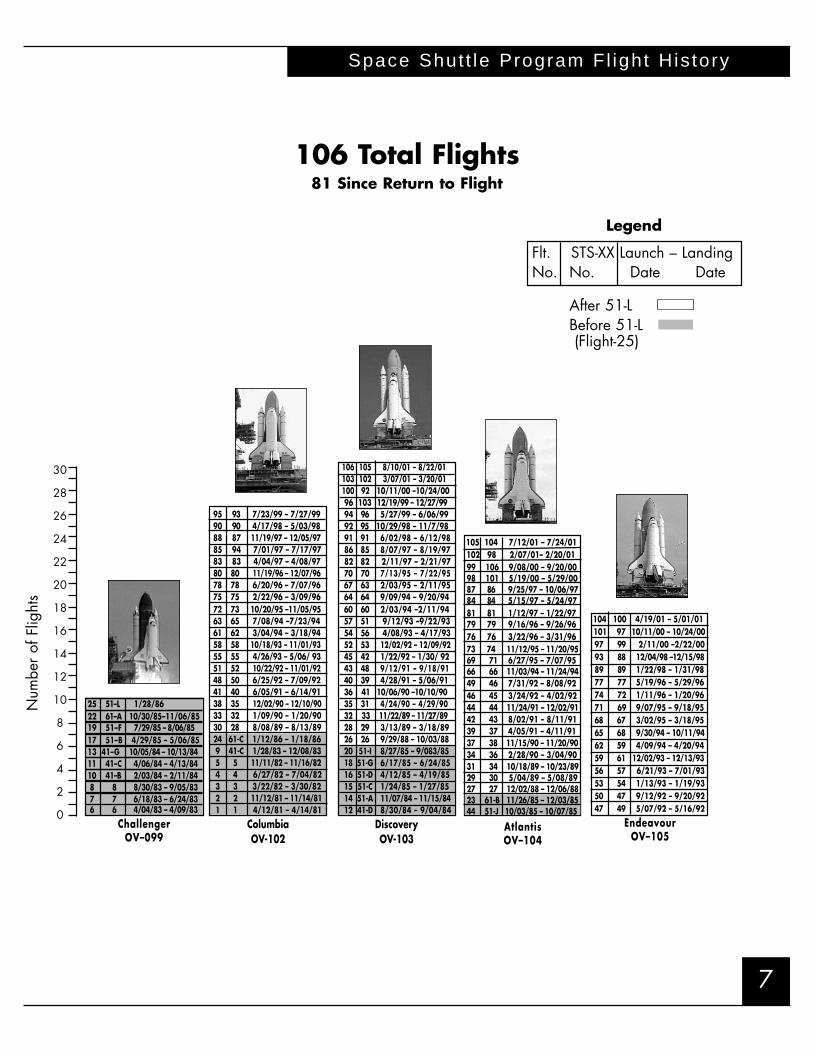
Space Shut t le Program Fl ight His tory
Num
ber
of F
light
s
104 100 4/19/01 – 5/01/01101 97 10/11/00 – 10/24/0097 99 2/11/00 –2/22/0093 88 12/04/98 –12/15/9889 89 1/22/98 – 1/31/9877 77 5/19/96 – 5/29/9674 72 1/11/96 – 1/20/9671 69 9/07/95 – 9/18/9568 67 3/02/95 – 3/18/9565 68 9/30/94 – 10/11/9462 59 4/09/94 – 4/20/9459 61 12/02/93 – 12/13/9356 57 6/21/93 – 7/01/9353 54 1/13/93 – 1/19/9350 47 9/12/92 – 9/20/9247 49 5/07/92 – 5/16/92
EndeavourOV–105
Legend
Flt. STS-XX Launch – LandingNo. No. Date Date
After 51-LBefore 51-L(Flight-25)
30
28
26
24
22
20
18
16
14
12
10
8
6
4
2
0
25 51–L 1/28/8622 61–A 10/30/85–11/06/8519 51–F 7/29/85 – 8/06/8517 51–B 4/29/85 – 5/06/8513 41–G 10/05/84 – 10/13/8411 41–C 4/06/84 – 4/13/8410 41–B 2/03/84 – 2/11/848 8 8/30/83 – 9/05/837 7 6/18/83 – 6/24/836 6 4/04/83 – 4/09/83
ChallengerOV–099
95 93 7/23/99 – 7/27/9990 90 4/17/98 – 5/03/9888 87 11/19/97 – 12/05/9785 94 7/01/97 – 7/17/9783 83 4/04/97 – 4/08/9780 80 11/19/96 – 12/07/9678 78 6/20/96 – 7/07/9675 75 2/22/96 – 3/09/9672 73 10/20/95 –11/05/9563 65 7/08/94 –7/23/9461 62 3/04/94 – 3/18/9458 58 10/18/93 – 11/01/9355 55 4/26/93 – 5/06/ 9351 52 10/22/92 – 11/01/9248 50 6/25/92 – 7/09/9241 40 6/05/91 – 6/14/9138 35 12/02/90 – 12/10/9033 32 1/09/90 – 1/20/9030 28 8/08/89 – 8/13/8924 61-C 1/12/86 – 1/18/869 41-C 1/28/83 – 12/08/835 5 11/11/82 – 11/16/824 4 6/27/82 – 7/04/823 3 3/22/82 – 3/30/822 2 11/12/81 – 11/14/811 1 4/12/81 – 4/14/81
ColumbiaOV-102
106 105 8/10/01 – 8/22/01 103 102 3/07/01 – 3/20/01100 92 10/11/00 –10/24/0096 103 12/19/99 – 12/27/9994 96 5/27/99 – 6/06/9992 95 10/29/98 – 11/7/9891 91 6/02/98 – 6/12/9886 85 8/07/97 – 8/19/9782 82 2/11/97 – 2/21/9770 70 7/13/95 – 7/22/9567 63 2/03/95 – 2/11/9564 64 9/09/94 – 9/20/9460 60 2/03/94 –2/11/9457 51 9/12/93 –9/22/9354 56 4/08/93 – 4/17/9352 53 12/02/92 – 12/09/9245 42 1/22/92 – 1/30/ 9243 48 9/12/91 – 9/18/9140 39 4/28/91 – 5/06/9136 41 10/06/90 –10/10/9035 31 4/24/90 – 4/29/9032 33 11/22/89 – 11/27/8928 29 3/13/89 – 3/18/8926 26 9/29/88 – 10/03/8820 51-I 8/27/85 – 9/083/8518 51-G 6/17/85 – 6/24/8516 51-D 4/12/85 – 4/19/8515 51-C 1/24/85 – 1/27/8514 51-A 11/07/84 – 11/15/8412 41-D 8/30/84 – 9/04/84
DiscoveryOV-103
105 104 7/12/01 – 7/24/01102 98 2/07/01– 2/20/0199 106 9/08/00 – 9/20/0098 101 5/19/00 – 5/29/0087 86 9/25/97 – 10/06/9784 84 5/15/97 – 5/24/9781 81 1/12/97 – 1/22/9779 79 9/16/96 – 9/26/9676 76 3/22/96 – 3/31/9673 74 11/12/95 – 11/20/9569 71 6/27/95 – 7/07/9566 66 11/03/94 – 11/24/9449 46 7/31/92 – 8/08/9246 45 3/24/92 – 4/02/9244 44 11/24/91 – 12/02/9142 43 8/02/91 – 8/11/9139 37 4/05/91 – 4/11/9137 38 11/15/90 – 11/20/9034 36 2/28/90 – 3/04/9031 34 10/18/89 – 10/23/8929 30 5/04/89 – 5/08/8927 27 12/02/88 – 12/06/8823 61-B 11/26/85 – 12/03/8544 51-J 10/03/85 – 10/07/85
AtlantisOV–104
106 Total Flights81 Since Return to Flight

Space Shut t le Program Hardware F low
8

9
Aerospace Technician Certification Program
The SSP has been active in the further develop-ment and recognition of workforce skills. TheAerospace Technician Certification Program is ajoint effort with participation by NASA, industry,and a consortium of schools from across the coun-try to establish certification of aerospace techni-cians to a higher standard than currently exists.The program makes use of a specialized curriculumand state-of-the-art instructional techniques toprovide a pool of “work-ready” employees for theSpace Shuttle and other aerospace programs.Brevard Community College (BCC) led the imple-mentation effort and has commenced classes at theBCC facilities located inside the Kennedy SpaceCenter (KSC) Center for Aerospace Education. Inaddition to technical support and guidance for theoverall program, the United Space Alliance (USA)is providing full scholarship funding for several participants in this initial class. Congressional andFlorida state government support for this initiativehas been outstanding.
Safety
Management commitment and employee involve-ment continue to be the driving influence in
Significant emphasis is placed on the protectionof the public, the crews, the workforce, and thehardware. The safety record of the Space Shuttle isa testimony to the skill and commitment of theSpace Shuttle Program (SSP) Team.
Quantitative Risk Assessment
The SSP is aggressively evaluating and developingthe implementation of quantitative risk assessmentmethods. The Shuttle System Safety Review Panel(SSRP) has been leading the combined efforts ofmultiple NASA centers and element contractors indeveloping the Space Shuttle probabilistic riskassessment (PRA). The Space Shuttle PRA willprovide quantitative risk information to aid in program decision-making. PRA techniques havealready been used extensively to evaluate the riskimpacts of system modifications and upgrades.Other PRA applications have included evaluationof risk reduction using the main engine advancedhealth monitoring system (AHMS) and the risktradeoff of extending the Space Shuttle nose gearversus designing more robust tires. With the PRAmodel, analysts can identify risk contributions andrelationships down to the system and piece partlevel. The first release of the Space Shuttle PRA,which is planned for March 2003, will model thevehicle from launch through landing.
Program Safety
William J. Harris, Manager, Safety andMission Assurance (JSC)
Employee CommitmentDrives UnprecedentedSafety Record…

improving safety in the workplace. Fewer employ-ees have been injured on the job as a result of theemphasis placed on safety. The Total RecordableCase Rate and the Lost Time Case Rate have bothdropped dramatically since 1997. In addition,there have been no Type A or B property damagemishaps this year, demonstrating a commitment tothe safe handling of spaceflight hardware. Type Cproperty damage mishaps are down by 40%.
The Space Shuttle Program Safety community is communicating more than ever before, sharinglessons learned and best practices that make theSSP even better. Senior safety managers represent-ing USA, Boeing - Rocketdyne, Lockheed Martin,ATK Thiokol, Pratt & Whitney, and HamiltonSunstrand have collectively formed the SSP
Program Safety
10
Contractor Safety Council. This Council meets on a regular basis to work safety issues that arecommon to the SSP. The Council’s charter estab-lishes a technical forum focused on understandingissues that impact programmatic safety and identi-fing initiatives designed to improve performance. An essential aspect of the Council is the ability to identify lessons learned and sharebest practices across the SSP Team. The Councilprovides a valuable source of experience and sub-ject matter expertise that will result in improvedsafety for the entire SSP. ◆

11
This initiative encourages increased use of industrial engineering methods across the Space Shuttle Program (SSP), ensuring that maintainability and human factors elements are adequately considered in new designs. The Industrial Engineering for Safety (IES) initiative isin the second year of the planned 5-year project, and currently has 25 projects and 8 studies funded.
These projects include large-scale efforts such as the EnhancedDiver Operated Plug for Booster Rewatering that results in reduceddiver workload and time at depth, improves plug installation, and automates the locking mechanism, to smaller scale projects such as one to improve thehandle on the mainengine fuel pump toreduce the potentialfor damage or injury.
The dramaticimprovements in risk reduction can be seen in the chart at right. The IES initiative will continue to define and imple-ment projects toimprove personneland hardware safety.
Indust r ia l Engineer ing for Safety
Joyce Rozewski, Manager, Industrial Engineering (KSC)
IES Program Risk Reduction
Ris
k A
sses
smen
t V
alu
e
IES Improves WorkplaceSafety, Reduces Risk toHardware…

promote and integrate process control as a part ofeveryday business, and over this year all of theprimes have instituted several new best practicesto improve process control within their organiza-tions and at their suppliers. Open sharing andcommunication of best practices through theProcess Control Focus Group have stimulated significant cross-pollination of good process control tools and practices among the primes. For example, as a result of this sharing, all of theprimes now have adopted a Stamp Warranty program as a best practice .
The efforts of the focus group are showingresults. This year several of the prime contractorshave shown marked reductions in process escapesand supplier nonconformances. This is a trend thatthe SSP will strive to continue through the effortsof the Process Control Focus Group. ◆
Process Control
The Process Control Focus Group continuesto actively promote process control awareness andimprovements across the SSP. The SSP has beenrecognized by government and industry as theleader in the area of process control, and the focusgroup continues to break new ground in findingways to reduce process escapes that could result inmission failure or loss of life.
The group’s mission is to reduce program risk by preventing process escapes. This is beingaccomplished by raising awareness of the processcontrol issue and motivating culture change with-in the supplier base, which consists of thousandsof suppliers across the country. The awarenessprogram has been very successful. A comprehen-sive marketing program was developed to targetthe supplier base with a variety of products thatare complementary in reinforcing the process control message. Suppliers are getting the processcontrol message through increased visits by primecontractors, and through supplier conferences andsymposiums that focus on process control. Twovideos, released by the Process Control FocusGroup, have been distributed widely throughoutthe supplier base, with 1,400 suppliers and over10,000 employees having watched the easy-to-understand process escape lessons in the firstvideo, “Success in Process Control.” This videoreceived a Bronze Telly award for superior qualityin production. The second video, “Countdown:Process Creep,” is set to follow this year with similar wide distribution. Posters, brochures, sup-plier-specific product fact sheets, CD-ROM minidiscs, and websites are additional tools being usedto reach supplier employees at the personal level.
A controlling Shuttle Program ProcessControl Management Plan governs the ProcessControl Program. Over the last year, each of theSpace Shuttle prime contractors has developedinternal process control implementation plans to respond to the Space Shuttle mandate. Theorganizations are changing their culture to
Indust r ia l Engineer ing for Safety
12

Figure 1 provides a comparison of the budget andexpenses between FY2000 and FY2001. The increasesin both capital and expenditures is due to the approval
of the safety upgrades for implementation.
Figure 2 highlights the success achieved by the SSPreducing required operating expenses. A significant buying power reduction has been absorbed while stillimplementing several safety upgrades.
13
The Space Shuttle Program (SSP) was ableto overcome numerous unprecedentedcost challenges this fiscal year, includingcritical infrastructure revitalizationrequirements, Orbiter maintenance down period cost growth, significant economic rate impacts, and cost growthdue to business base decline and criticalskills requirements in several programareas. Several of these challenges will con-tinue to affect the program through thebudget horizon and will need continualmanagement attention. Several safetyupgrades have been funded this fiscalyear, moving from the definition to theimplementation phase. ◆
Resource Management
James B. CostelloManager, Business Office (JSC)
Space Shuttle Program Meets Fiscal Challenges…

Space Shut t le Program Development
14
crew situational awareness, especially for abort situations, and by significantly improving flightcrew operational margins in responding to time- and safety-critical system failure scenarios. Solidtechnical progress was also made on the extremelyimportant SSME AHMS safety upgrade project.That project completed a Critical Design Reviewfor Phase 1 and proceeded into system develop-ment. The AHMS project team also made excellentprogress in developing system requirements, systemsanalysis, and a preliminary implementation plan forAHMS Phase 2, which is a proposed major exten-sion of Phase 1 capabilities. The External TankFriction Stir Weld Project completed the majorfacility modifications in the Michoud AssemblyFacility (MAF) needed to accommodate the newwelding tooling. The welding equipment, whichcompleted development in 2001, will be shipped toMAF early in 2002 for installation and checkout.
Systems analysis and prioritization of proposedsystem safety upgrade candidates continues to beupdated in support of management investmentdecisions. Program elements continue to supportthis prioritization effort and the development ofanalysis tools to provide relative quantification ofrisk reduction potential, as shown on page 15.
Excellent progress was made implementingour ambitious plans for a vigorous safety and supportability upgrade program. Significant milestones were achieved on the Cockpit AvionicsUpgrade (CAU), SSME Advanced HealthManagement System (AHMS), External TankFriction Stir Welding (FSW), improved MainLanding Gear Tire & Wheel, Long Life AlkalineFuel Cell (LLAFC), and ground Checkout andLaunch Control System Projects.
Development efforts on each of these will continue in 2002. Excellent progress was alsoaccomplished in defining, analyzing, and planningthe proposed electric auxiliary power unit (EAPU)and solid rocket booster (SRB) thrust vector con-trol/auxiliary power unit (APU) upgrades.Implementation of these two projects has beendeferred due to technical readiness of the EAPUand overall SSP funding priorities.
Completion of the project definition and formulation phase of the CAU Project was a majorachievement. After an intensive requirements andplanning effort, this project received managementapproval to proceed into implementation. TheCAU will provide a major increase in Space Shuttle operational safety by significantly improving flight
Elric N. McHenry, Manager,
Space Shuttle Development (JSC)
Development Milestonefor Cockpit AvionicsHighlights Progress onSafety Upgrades…

15
hydraulics to move the Orbiter’s main engines,landing gear, and aerodynamic surfaces duringflight. The primary benefit will be to replace thevolatile, toxic hydrazine fuel and high-speed gasturbine with batteries and an electric motor. Thischange will significantly reduce risks associatedwith potential fuel leaks in flight and duringground handling. Major design and technologydevelopment occurred over this year; however,implementation has been delayed while furtherstudy of options to reduce the cost and weight ofthe system is completed.
Main Landing Gear TireRedesign of the Orbiter’s main landing gear
tire and wheel will increase the tire load capacityby 20% by adding 2 more plies to the existing 16 and by adding new belt material. This addedmargin will reduce the risk of a tire failure andincrease the Orbiter’s tolerance to cross winds
Space Shut t le Program Development
Safety Benefits of Space Shuttle Upgrades
Safety Upgrades
Cockpit Avionics Upgrade The CAU will facilitate better use of the
new glass cockpit. The upgrade will provide thecomputers, interfaces, and software that willincrease the amount of information that can be displayed to the crew. These display improvementswill provide added crew insight into failures,significantly reduce crew workload, increase aware-ness during critical flight situations, and enhancethe caution and warning system for rapid problemresolution. Over the past year, the CAU projectteam completed a very successful formulation effort and has received authority to proceed intoimplementation.
Electric Auxiliary Power UnitAn EAPU was evaluated as a replacement for
the existing hydrazine APU that drives the
✓ x ✓ x x x✓ ✓ ✓ ✓ ✓ ✓✓ ✓ ✓ ✓ ✓ x✓ ✓ ✓ ✓ x x✓ ✓ x x x x

Space Shut t le Program Development
16
Supportability Upgrades
Auxiliary Information System (AIS)The AIS will be a digital data recorder to
replace the modular auxiliary data system, an ana-log tape recorder. Analog tapes are no longermanufactured for this recorder, and a replacementsystem is needed. The AIS will record and dump avariety of valuable engineering data and high-speed main engine vibration data. The AIS is currently in the formulation phase.
Long Life Alkaline Fuel CellThe LLAFC will double the life of fuel cells
to 5,000 hours. Currently the LLAFC effort is inthe implementation phase, and full-scale fuel cellstacks are undergoing long-duration testing,which has been completely successful thus far.
Supportability Upgrades UnderConsideration
In addition to these supportability upgrades, theSpace Shuttle Program Development office hasbeen aggressively evaluating other supportabilityimprovement upgrades. Supportability upgradesaddress flight hardware availability assurance andoperational improvements. Flight hardware avail-ability projects consider obsolescence, failure rates,repair times, and inventory attrition. Operationalimprovement candidates include maintainability,mission success, flight preparation, vehicle turn-around, and cost-reduction considerations.Significant supportability upgrades currentlybeing evaluated are the Orbiter’s Ku-band communication and radar system, SRB integrated electronics assembly (IEA), and theSRB automated booster assembly checkout system (ABACS). ◆
while accommodating higher landing speeds. Thewheel changes will compliment the tire’s new loadcapacity. Testing of nine different tire alternativeshas been completed as part of this effort.
Advanced Health Management SystemThis upgrade provides additional health
monitoring capability for the SSME. Thisupgrade is planned in two phases. Phase I, whichhas been approved for implementation, upgradesthe SSME controller and adds a real-time turbo-pump vibration redline system. Phase II, which is currently in formulation, adds a health manage-ment computer (HMC) to run a more advancedreal-time vibration redline system and a linear engine model to identify pending failuresbefore the failures become catastrophic. Eachphase reduces the risk of a catastrophic enginefailure by more than 20%.
Solid Rocket Booster (SRB) AuxiliaryPower Unit UpgradeThe SRB project completed study of severalreplacement options for its APU used for thrustvector control during ascent. The SRB APU, like that of the Orbiter, is based on a hydrazine-powered turbine that drives the hydraulic systempump. The goal of this upgrade is to eliminate theinherent hazards associated with the toxic, flamma-ble hydrazine-powered system. The design optionselected as part of this year’s effort was a pressurizedhelium-powered turbine that drives the hydraulicsystem pump. Significant design detail has beenadded during this year’s formulation effort.
Friction Stir WeldingThe FSW, a solid-state welding process for
replacement of arc welding of external tank longi-tudinal welds, has continued development thisyear. FSW produces very high weld strength,near that of the parent material; results in near-zero defects; and significantly reduces manufacturing cycle times.

17
Miss ion Summar ies
STS-92 – The 100th Space Shuttle FlightThe STS-92 (ISS-3A Assembly) mission onDiscovery (OV-103), with six U.S. astronautsand one Japanese astronaut on board, was initiated on October 11, 2000, and began the fifth U.S. mission to the ISS. The primarymission objective was to launch, rendezvous,and dock with the orbiting ISS and deliver the3A launch package. The Z1 integrated trusssegment was attached to the Node 1 zenithport and the pressurized mating adapter 3(PMA3), which was launched on a spacelogistics pallet, was mated to the Node 1 nadir port. Two direct current (DC)-to-DC converter units were installed on Z1 andchecked out successfully. The Z1 and PMA3 power and data umbilical wire harnesses were reconfigured in preparation to support STS-97/4A docking to PMA3. Additionally, two extravehecular activity (EVA) tool stowage devices were relocated from the SLP to Z1.
The IMAX 3D cargo bay camera successfully documented scenes of the Space Shuttle approach, ISS assembly tasks, EVA crew activities, and undocking. All planned and get ahead tasks were completed with four EVAs in a total time of 26 hours and 38 minutes.
The ISS vehicle was raised approximately 3.6 nautical miles with three Space Shuttle reboost maneuvers that preserved ISS propellants in preparation for the STS-97/4A launch. The ISS vehicle was left in a 214 x 202-nautical miles orbit.

Miss ion Summar ies
18
STS-97The STS-97 (ISS-4A) mission on Endeavour, with four U.S. astronauts and one Canadian astronaut onboard, began its 11-day mission with an on-time Kennedy Space Center (KSC) liftoff at 9:06 p.m. CDT, November 30, 2000. ISS-4A was the sixth U.S. mission to the ISS.
STS-97 delivered the first set of U.S. solar arrays and batteries, as well as radiators. Endeavour and its crew spent seven days docked to the ISS, which was staffed by its first resident crew. The STS-97 crew conducted three spacewalks and attached and unfurled the 73-meter (240-foot) solar arrays,the largest arrays ever deployed in space. A communications system for voice and telemetry also was installed. ◆

19
STS-98The STS-98 (ISS-5A) mission on Atlantis(OV-104), with a five-member crew,was initiated with a KSC liftoff onFebruary 7, 2001, at 5:13 p.m. CST.This was the seventh U.S. mission tothe ISS and the first of six plannedresearch modules to be added to the ISS. The U.S. Destiny laboratorymodule will serve as the command andcontrol center for the entire
Miss ion Summar ies
complex. Following rendezvous anddocking at ISS PMA3, the 5A crew successfully removed PMA2 from Node1 of the ISS, installed the U.S. Lab onNode 1, re-installed PMA2 on the for-ward common berthing mechanism of the U.S. Lab, performed three successful EVAs, and several get-ahead tasks. The crew also successfully completed all transferoperations including real-time additions and deletions to the transfer plans. Additionally, the crew performed seven reboost maneuvers increasing the overall ISS altitude by 13 nautical miles.

Miss ion Summar ies
20
STS-102The STS-102 (ISS-5A.1) 13-day mission onAtlantis was initiated with an on-time KSC liftoffon March 8, 2001, at 5:42 a.m. CST, andbegan the eighth U.S. mission to the ISS. Thecrew consisted of seven going up and sevencoming down, completing the first ISS crewrotation of three crewmembers. Two space-walks were successfully performed, consistingof scheduled and additional tasks. This missionwas the first flight of the Leonardo multi pur-pose logistics module (MPLM), and the fourthflight of the integrated cargo carrier, used forthe mounting of external transfer items.
Once the rendezvous and docking with the ISS was completed, the first EVA was per-formed which included tasks that would enablethe relocation of PMA3 from the Node 1 nadirlocation to the Node 1 port location via theremote manipulator system (RMS). Berthing ofthe MPLM at the Node 1 Nadir location wasthen completed using the RMS.
In addition to the ISS activities, there werethree payloads in the cargo bay: wide-bandShuttle vibration forces measurement(WSVFM), get-away special-783 (GAS-783),and space experiment module (SEM-09).
The WSVFM, managed by the JetPropulsion Laboratory, obtained flight meas-urements of the vibration forces actingbetween a payload and its mounting struc-ture, including acceleration data at high andlow frequencies.
Both the GAS-783 and the SEM-9 are managed by the Goddard Space FlightCenter (GSFC). GAS-783 contained 47experiments provided by schools in the St.Louis, Missouri, area, which were completelypassive and self-contained within a standard-sealed 2.5- cubic-foot GAS canister. TheSEM-9 experiment used a GAS canister,divided into 10 modules, to accommodatesmall zero- or micro- gravity experiments. Theprimary science objective was the quantifica-tion of extraterrestrial particles and otherorbital debris present in the Orbiter bay. This“passive” sponge collected microscopicdebris on-orbit and retained this debris forpostflight evaluation by students ranging fromkindergarten through university.

21
STS-100The STS-100 (ISS-6A) mission on Endeavour was initiated with an on-time KSC liftoff at 1:40 p.m. CDT on April 19, 2001. The ISS-6A mission was the ninth U.S. mission to theISS. The crew of seven was the most diverse international crew to ever fly in space with four U.S. astronauts, one Canadian SpaceAgency astronaut, one European Space Agencyastronaut, and one cosmonaut from the RussianAviation and Space Agency. A rendezvous anddocking to the ISS Stage 5A.1 occurred at 8:59a.m. CDT on April 21, 2001. During the eightdocked days, two EVAs were performed to installthe space station remote manipulator system, theultra high frequency (UHF) antenna, and the direct current switching
unit critical spare in addition to the removal of the early communications system antenna. Onnon-EVA days, activities such as middeck hard-ware transfer, utilization experiment transfers,water transfer, and unloading of the MPLM wereperformed. Specific scenes of the Orbiterapproach and undocking, ISS assembly tasks, and EVA activities were documented using theIMAX 3D in-cabin camera and the IMAX cargobay camera-3D (ICBC-3D). Two Orbiter reboostsof the ISS were completed successfully to increasethe ISS altitude, resulting in an orbit of 219 x 206nautical miles.
Miss ion Summar ies

Miss ion Summar ies
22
STS-104The STS-104 (ISS-7A) mission on Atlantis successfully launched on time from KSC on July 12, 2001. The ISS-7A mission was the tenth U.S. mission to the ISS, and consisted of a five-member crew. A successful rendezvous and docking to the ISS Stage 6A occurred at10:05 p.m. CDT on July 13, 2001. During the eight docked days, three EVAs were per-formed to install the joint airlock and four high pressure gas tanks. Eight EVA get-ahead tasks were also performed. Inside the orbiting vehicles, airlock activation andcheckout, middeck hardware transfer, utilization experiment transfers, and water transfer,were performed. Specific scenes of the Orbiter approach and undocking, ISS assemblytasks, and EVA activities were documented using the IMAX-3D in-cabin camera, and theIMAX ICBC-3D. Three Orbiter reboost periods of the ISS were completed, successfullyincreasing the ISS altitude 8 nautical miles .

23
STS-105The STS-105 (ISS-7A.1) mission on Discoverywas initiated with an on-time KSC liftoff at4:10 p.m. CDT on August 10, 2001. The ISS-7A.1 mission was the eleventh U.S. mission to the ISS, and consisted of a seven-member crew (three ISS crewmember rotation).After docking, the MPLM, Leonardo, was successfully un-berthed and installed on Node1 of the ISS. During the eight docked days, theExpedition 3 crew handover and two EVAswere performed, and all transfers between the Shuttle middeck, MPLM, and ISS werecompleted. Two ISS reboosts were also per-formed, increasing the ISS altitude from 212 to 219 nautical miles.
During the docked time, seven new pay-loads were transferred from the Space Shuttleto the ISS to support Increment 3 activities, andsix payloads and numerous data were trans-ferred back from the ISS to the Space Shuttlefor return and scientific evaluation. Among thepayloads transferred to the ISS was the firstcommercial payload, DREAMTiME, a high definition television camcorder that captured anumber of activities on both the Space Shuttleand the ISS. Also transferred were the firstexternal payloads: two materials InternationalSpace Station experiments (two MISSEs), whichwere transferred and deployed during the firstEVA. In addition to the MISSEs, the first EVAalso transferred the early ammonia servicer.The second EVA transferred and installedlaunch-to-activation cables for the S0 truss ele-ment as a get-ahead task for the 8A mission.Both EVAs were successfully completed duringthe mission.
In addition to the ISS activities, the cargo bay contained several GSFC managedpayloads. These included the HitchhikerExperiments Advancing Technology (HEAT) and a GAS payload, G-780.
HEAT was comprised of the SimpleSatejectable satellite, the advanced carrier equipment (ACE) avionics system, GAS payload 774 (G-774) and the SEM.SimpleSat was an engineering test satellite designed to evaluate the use of inexpensive
commercial hardware on spacecraft. After the Space Shuttle undocked from the ISS, the crew executed a flawless deploy of the SimpleSat satellite. SimpleSat will orbit the Earth for about 5 months before atmospheric drag will cause it to re-enter.
The ACE was designed as an enhancement of and eventual replacement for the existing Hitchhiker (HH) avionics as the power and data interface to the Orbiter electronics for HH payloads. ACE provides the same services and electrical interfaces as the HH avionics, but with enhancements and system redundancy. STS-105 marks the first flight of the ACE assembly. Over the course of the 12-day flight, ACE met its mission success objectives.
The STS-105 crew successfully commandedthe operations of the G-774 and G-780 payloads on orbit.G-774 was a GAS experiment that had the objective of validating the model for theoretical predictionsof smolder propagation to enhance our under-standing of the smolder hazard. G-780 was aGAS experiment that investigated cell growth in micro-gravity and was sponsored by theMayo High School in Rochester, Minnesota.
The SEM canister was comprised of 10 small-enclosed modules, each containing several passive experiments designed and constructed by students.
Miss ion Summar ies

MSFC Shut t le Env i ronmenta l Assurance
24
…and proactively manage materials obsolescence.Interfaces with groups within NASA, includingthe NASA Materials Replacement TechnologyTeam, the Headquarters and Centers’Environmental Management Offices, and theAcquisition Pollution Prevention Office, alongwith other government agencies and private industry have been developed to leverage resourcesand enhance technology transfer opportunities.
The increasing promulga-tion of international, federal,state, and local environmentalregulations is affecting allaspects of aerospace manufac-turing operations. The ShuttleEnvironmental Assurance(SEA) Initiative assures thatregulations are identified,reviewed for impact, andreported through the appropriate channels.
Potential issues are analyzed and categorized inaccordance with the Issue andContinuous Risk Managementprocess. Issues currently inwork by the SEA Initiative are highlighted at right. ◆
Jolene J. Martin, Manager,
Shuttle Integration Office (MSFC)
RSRM•Chromium in conversion coatings•High VOC coatings•Hypalon paint replacement•TCA elimination
ET•Chromium in alkaline cleaners•Chromium in conversion coatings•Chromium in primers•High VOC coatings
SSV•Chemical paint stripper alternatives•Chromium in conversion coatings•Chromium in primers•HCFC 141b blowing agent•High VOC coating• TCA elimination
SSME•Chromium in
conversion coatings•Chromium in primers
SRB•Alternate dry film lubricant•Chromium in conversion coatings•Chromium in primers•HCFC 141b blowing agent•High VOC coatings•Hypalon paint replacement
Open SEA Initiative Issues
SEA PromotesCooperative Effort toAchieve EnvironmentalExcellence…
25
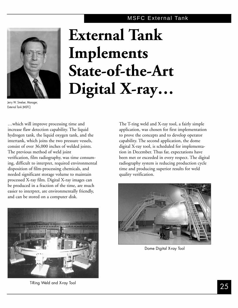
MSFC External Tank
…which will improve processing time andincrease flaw detection capability. The liquidhydrogen tank, the liquid oxygen tank, and theintertank, which joins the two pressure vessels,consist of over 36,000 inches of welded joints.The previous method of weld joint verification, film radiography, was time consum-ing, difficult to interpret, required environmental disposition of film-processing chemicals, andneeded significant storage volume to maintainprocessed X-ray film. Digital X-ray images can be produced in a fraction of the time, are mucheasier to interpret, are environmentally friendly,and can be stored on a computer disk.
The T-ring weld and X-ray tool, a fairly simpleapplication, was chosen for first implementationto prove the concepts and to develop operator capability. The second application, the dome digital X-ray tool, is scheduled for implementa-tion in December. Thus far, expectations havebeen met or exceeded in every respect. The digitalradiography system is reducing production cycletime and producing superior results for weld quality verification.
Jerry W. Smelser, Manager,External Tank (MSFC)
T-Ring Weld and X-ray Tool
Dome Digital X-ray Tool
External TankImplements State-of-the-Art Digital X-ray…

MSFC External Tank
26
External Tank (ET) Friction Stir Weld(FSW) Safety Upgrade
Training hardware, facility modifications, andinitial production tooling have all been completedin support of the July 2002 implementation of fric-tion stir welding (FSW) in the ET production line.FSW, which will be used on the liquid oxygen andliquid hydrogen barrel section longitudinal welds,will provide increased safety margin and reducemanufacturing cost and schedule.
The FSW trainer tool, a 1/4-scale replication ofthe production tool, was delivered to the MichoudAssembly Facility (MAF) in October.
The MAF modifications, which included construction of a 90-foot long, 50-foot wide, and 15-foot deep pit to house the production tooling, wascompleted on time without interference with theongoing ET manufacturing.
FSW Trainer Tool
FSW Facility
Lean Manufacturing/StatisticalProcess Control
An aggressive lean manufacturing/statisticalprocess control plan is under way and showingimprovements in quality and cost metrics.Targeted worksites undergo a week-long KaizenEvents analysis to optimize workspace and work-flow. Statistical process control is employed as afollow-up to systematically refine and reduceprocess variability. As part of this effort, metricsare developed to evaluate long-term success.
Performance measurements on convertedworksites confirm improvements in quality, cost,required manufacturing floor space, andpart/employee travel distance.
Improved Workspace / Workflow
Initial Workspace / Workflow

27
MSFC External Tank
External Tank Paperless ManufacturingExecution System
In fiscal year (FY) 2003, all work orders andsupporting documentation required to assemblean ET will be generated and processed electroni-cally. This new system will provide improvementsin work instruction and non-conformance docu-mentation quality, process control, and opera-tional efficiency.
To prepare for this transition, and to substan-tiate the benefits prior to implementation, aPaperless Manufacturing Pilot Center was established. Teams of operators and engineersspent several months reviewing the capabilitiesand limitations of various products. Followingthis demonstration in FY2001, the project wasapproved for implementation.
Concurrent with the implementation of thisnew capability, a fiber-optic network is beinginstalled to support the increased capacity requirements of the paperless system.
Following implementation in FY2003, ET manufacturing will see improved efficiency,reliability, and productivity. ◆
Retractable Pin FSW Tool
PMES Workstation
Several risk-mitigation steps have been implementedon this project to ensure successful implementation.One of the more notable items surfaced by the riskmitigation plan was the potential for a lack-of-pene-tration in the tapered barrel sections. This risk hasbeen mitigated by the addition of a retractable pinFSW tool that includes laser sensors to allow real-timecompensation for thickness variations that occur inthe tapered welds.
All elements of the FSW Project are on sched-ule to support implementation in July 2002 andwill be a major enhancement to the producibilityand safety of the Space Shuttle’s ET.

MSFC Reusable Sol id Rocket Motor
28
…is a continual focus for the Reusable SolidRocket Motor (RSRM) Project. For the eleventhconsecutive year, all motor segments were deliv-ered on schedule. All flown RSRMs performed asdesigned. Postflight disassembly and inspectionsduring fiscal year (FY) 2001 revealed no signifi-cant anomalies.
FY2001 Safety Performance
Safety continues to be the principal focus in themanufacture of the Space Shuttle Program’s RSRM.This is reflected in the job-related accident frequen-cy rates at ATK Thiokol Propulsion, which havebeen well below the rates for similar industries, aspublished by the Bureau of Labor Statistics. In fact,the company’s record in contract year 2000 forOSHA recordable and lost workday injury rates wasat record lows for the past several years.
Lost Workday Case Incidence Rate
ATK Thiokol reached a number of significantsafety milestones this past year:
❖ The Test Area surpassed 4.3 millionhours, or 12.5 years, without a lost-timeaccident.
❖ The Nozzle Work Center surpassed 2.1 million hours, or 6.7 years, without alost-time accident.
RSRM Independent Assessment
The Space Shuttle Program Office charteredan independent team to assess RSRM operationsrelative to a broad spectrum of program issues.The team, using independent retired NASA andcorporate members, conducted their review at ATK Thiokol on March 4-9, 2001. Focus areasof the audit included:
❖ Facilities, equipment, and tooling❖ Nondestructive evaluation (NDE) processes❖ Material receiving inspection practicesThe final report issued on April 11, 2001,
concluded:❖ The RSRM is meeting all performance
requirements.❖ The ATK Thiokol workforce is attuned
to the criticality of process control toRSRM safety.
❖ Facilities, tooling, and equipment are ingood condition and are being maintainedin an effective manner.
Michael U. Rudolphi, Manager, Reusable Solid Rocket Motor (MSFC)
Ensuring On-TimeDelivery and On-TargetPerformance…

29
MSFC Reusable Sol id Rocket Motor
❖ Inspection and NDE tooling and equipment are meeting existing require-ments and are maintained in good operating condition.
❖ Materials receiving inspection is thoroughand geared to detecting inferior products.However, these vendor products representa risk to the RSRM program that requirescareful management.
Responsible Reason for ObsolescenceMC = Metal Components G = Government Regulation
I = Insulation (EPA, OSHA, etc.)P = Propellant V = Vendor Economics
N = Nozzle I = Industrial/Safety HazardFA = Fleet Assembly N = Natural Disaster
O = Obsolescent Technology
RSRM Obsolescence Threats
RSRM Obsolescence Mitigation
The RSRM is unique; it is comprised ofdiverse categories of uncommon processes, materials, and components that face the constantchallenges presented by obsolescence issues thathave the potential to adversely affect the RSRM.Continuous surveillance is required to anticipateand implement the necessary replacement tech-nologies to manufacture and deliver the RSRMwith unaltered configuration and performancecharacteristics. The figure on the left shows manyof the obsolescence challenges currently facing the RSRM Project.
Automated Eddy Current InspectionSystems for RSRM Refurbishment
During refurbishment after flight, all RSRMhardware is cleaned to bare metal and subjected tonumerous inspections: visual, dimensional, andnon-destructive evaluation (proof test, magneticparticle, dye penetrant, eddy current, ultrasonicshearwave, etc.). Magnetic particle and dye pene-trant inspections are visually-based; i.e., they rely onthe human eye as the sensor to detect indications.Although these visual-based inspections are support-ed by extensive probability-of-detection studies andhistory, new electronic sensor-based inspectionsoffer advantages. The RSRM Project will replacethese visual-based inspections with sensor-basedinspections to improve the reliability, control, anddata storage of NDEs. Using sensors also allowsautomation of the inspection. Other benefitsinclude inspector variability and subjectivity elimi-nation, digital evaluation of indications, ability tocalibrate, data archiving, reduced cycle time, andreduction of waste streams.
Delivery and installation occurred in early2001, with testing successfully conducted on full-scale hardware, including flight support motor no. 10 (FSM-10). Following the successfulcompletion of qualification testing, implementationof the new systems as a replacement for some of the current inspections is planned to begin inearly 2002.

barrier in an effort to preclude gas penetration tothe O-ring sealing system. In an effort to reduce oreliminate the occurrence of gas paths through thepolysulfide, a design change eliminating the polysul-fide and incorporating a J-leg with a carbon ropethermal barrier is being tested.
The RSRM nozzle-to-case J-leg incorporates a pressure actuated flap (J-leg) insulation designthat, when deflected, is placed in circumferentialtension. An enhancement for the J-leg configura-tion is the installation of a carbon rope thermalbarrier located at the step region of the joint. Inthe event of gas leakage beyond the J-leg region,the thermal barrier will cool and spread any gas,thus eliminating potential heat effects on the outboard leak check barrier.
FY2001 accomplishments include the firing ofFSM-9, the first full-scale static test with theimproved J-leg configuration. The joint performedits intended function by keeping hot gas away from the joint seals. No hot gas penetration past the J-leg or the carbon rope thermal barrier wasobserved. The next full-scale static test, FSM-10,will include a channel through the J-leg to the thermal barrier. The FSM-10 firing is scheduled for August 2002.
Flight Support Motor No. 9
Full-scale RSRM static test motors are periodi-cally tested to confirm the performance and safety of RSRM systems and certify design, component,material, and process changes. FSM-9 was success-fully static tested on May 24, 2001. Extensive instru-mentation (576 channels) gathered data in supportof the 103 test objectives. While data evaluationcontinues, the FSM-9 test was a complete success. ◆
MSFC Reusable Sol id Rocket Motor
30
Digital X-ray Inspection for RSRM Components
An effort is under way to develop and demonstratestate-of-the-art digital X-ray systems that will eventually replace the current wet-film technology.This new inspection technique, which actually usesthe same X-ray energy source as the current system,will be used to provide the NDE of phenolic nozzle components as well as loaded and insulatedmotor segments.
The digital image can be evaluated, enhanced,and stored as a digital file for future reference. Thenew digital system provides better image quality aswell as improved image manipulation and enhance-ment capabilities. The digital data will allow for near-instantaneous retrieval of all images, makinganomaly investigations and other data review activities more efficient.
Nozzle-to-Case Joint J-leg Configuration
The current RSRM nozzle-to-case joint employs apolysulfide mastic adhesive bondline as a thermal
Inspection Process
Digital Radiography CCD System
Nozzle-to-Case Joint J-leg Configuration
31
MSFC Sol id Rocket Booster
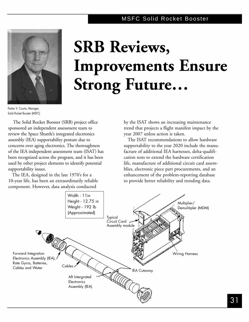
The Solid Rocket Booster (SRB) project officesponsored an independent assessment team toreview the Space Shuttle’s integrated electronicsassembly (IEA) supportability posture due to concerns over aging electronics. The thoroughnessof the IEA independent assessment team (ISAT) hasbeen recognized across the program, and it has beenused by other project elements to identify potentialsupportability issues.
The IEA, designed in the late 1970’s for a 10-year life, has been an extraordinarily reliablecomponent. However, data analysis conducted
by the ISAT shows an increasing maintenancetrend that projects a flight manifest impact by theyear 2007 unless action is taken.
The ISAT recommendations to allow hardwaresupportability to the year 2020 include the manu-facture of additional IEA harnesses, delta-qualifi-cation tests to extend the hardware certificationlife, manufacture of additional circuit card assem-blies, electronic piece part procurements, and anenhancement of the problem-reporting databaseto provide better reliability and trending data.
Parker V. Counts, Manager,Solid Rocket Booster (MSFC)
SRB Reviews,Improvements EnsureStrong Future…
Forward IntegrationElectronics Assembly (IEA),Rate Gyros, Batteries,Cables and Water Cables
IEA Cutaway
Wiring Harness
Multiplier/Demulitipler (MDM)
TypicalCircuit CardAssembly module
Width - 11inHeight - 12.75 inWeight - 192 lb(Approximated)
Aft IntergratedElectronicsAssembly (IEA)

MSFC Sol id Rocket Booster
32
SRB Advanced Thrust Vector Control(TVC) Completes Formulation, Readyfor Implementation
The TVC upgrade, one of the major safetyupgrades being considered by the Space ShuttleProgram (SSP), has completed the formulationphase and is now ready for implementation. Theproposed new TVC system, designed to reducethe chance of a catastrophic failure, uses gaseoushelium to spin a turbine. The turbine provideshydraulic power to gimbal the reusable solid rocket motor nozzles to steer the Space Shuttlevehicle during flight. The current system is powered by hydrazine.
Technology demonstration testing was conductedon numerous viable concepts to determine the optimum candidate. Those evaluated included anelectric motor powered by thermal batteries, a directhydraulic pressurization concept, a solid propellantgas generator, and the helium-powered turbine.
Subsequent to the demonstration testing, acomprehensive trade study was performed prior to the selection of the helium-powered auxiliarypower unit, (HeAPU), as the optimum replace-ment. It was chosen because it could achieve thedesired safety enhancement for the lowest cost,schedule and risk. The HeAPU will increase flightsafety by approximately 9.5%.
Detailed programmatic reviews were successfullycompleted to baseline all requirements and projectplanning documentation. Cost and schedule estimates were developed based on the informationobtained during the formulation phase. In addition,modeling and early development testing were con-ducted to identify and mitigate performance risks.
SRB’s New Command ReceiverDecoder
The most advanced, secure range safety technolo-gy available, the Solid Rocket Booster Project’s command receiver decoder (CRD), has completedthe development and qualification phase and hasmoved into production. The first flight set is sched-uled for delivery in fiscal year 2002. The CRD
replaces the integrated receiver decoder (IRD) andthe range safety distributor (RSD) of the RangeSafety System.
The CRD Project was initiated because of ahardware supportability threat due to electroniccomponent obsolescence. A replacement concept,which combined the IRD functions with the distribution functions of the RSD, was selectedbecause it provided a simplified system, reducedweight, and eliminated a line replaceable unit.
The CRD design addresses obsolescence issuesand increasing maintenance and supportability
SRB’s New Command Receiver Decoder
Comparison of IRD/RSD and CRD Configurations

33
MSFC Sol id Rocket Booster
concerns in the current IRD / RSD fleets.Supportability was designed into the CRD tolower operations costs by simplifying installation,testing, and refurbishment. The design effectivelyeliminates a line replaceable unit and the associat-ed vendor sustaining engineering, test set, andlogistics costs.
New SRB Radar Tracking ControllerSuccessfully Flown on STS-100
The Solid Rocket Booster Project successfullyflew the C-band controller (CBC) for the SRBradar beacon tracking system (SRBTS) on STS-100. The SRBTS provides enhanced performance for the C-band tracking radar. TheC-band radar is one of three redundant vehicletracking methods used for the Space Shuttle. TheCBC was designed, certified, and manufactured asan in-house United Space Alliance and MarshallSpace Flight Center project.
The CBC design consists of an upper housing,which contains electronics and input/output connectors, and the lower housing, which contains an integrated battery power supply. The lowerchamber can be opened to change the internal alkaline battery pack without exposing or disturbingthe electronics.
Using commercial-off-the-shelf (COTS) MilSpec components and technology for the selectionof batteries, components, and connectors, theCBC provided an immediate cost savings of$20,000 per flight compared to the existing system. Other improvements include simplified
manufacturing and improved reliability. Anotherperformance gain of the CBC is the weight reduction of approximately 480 pounds per flight(240 pounds per booster).
In summary, the CBC was designed withCOTS hardware resulting in inexpensive but reliable flight hardware that will transport us wellinto the 21st century.
SRB Independent OperationsAssessment Team (IOAT)
The SSP requested each Space Shuttle projectselect an independent team to assess their hardware operations. The SRB Project selected anindependent team with the prime objective toreview the use of reusable hardware. Specifically,the team addressed the refurbishment and acceptance requirements/screens, maintenanceprocedures and instructions, and developed recommended actions to mitigate concerns ofaging, wear, and tear. The team initiated its effort in January 2001 and presented findings and recommendations to the Shuttle ProgramManager in May.
The IOAT concluded SRB operations “are wellpostured to support the Space Shuttle Manifest inthe foreseeable future” with the implementationof recommended actions. The recommendationsfocused on enhancing the use of trending and statistical process control; performing periodicreviews of operational requirements based on pastexperience and data; assessing the requirementsand plans for vendor audits; revisiting the respon-sibilities involved in the procurement of parts and materials; reassess the use of finger printingmaterials for aging, wear and tear; and reevaluat-ing inspection, repair, and maintenance practices.
To further enhance SRB hardware reuse, theSRB Project decided to develop an SRB HardwareReuse Plan. The purpose of this plan is to captureand describe reuse requirements, processes, and procedures. This will allow development of proactive plans to mitigate reuse concerns for thelife of the Space Shuttle. ◆

MSFC Space Shut t le Main Engine
34
George D. Hopson, Manager, Space Shuttle Main Engine (MSFC)
The advanced health management system(AHMS) is a two-phase safety upgrade projectthat will reduce Space Shuttle Main Engine(SSME) catastrophic ascent risk by more than40%. This risk reduction comes through theapplication of improved high-pressure turbopumpvibration sensing technology combined withadvanced health management algorithms, enginemodeling, and real-time signal processing technol-ogy. Additionally, implementation of AHMSPhase 2 will introduce two new potential mitiga-tion actions for SSME failures – single enginethrottle-down and mixture ratio adjustment.These failure mitigation actions, when taken inlieu of engine shutdown, will enable the SpaceShuttle to achieve a safer abort mode or possiblyeven turn what would otherwise be an abort intoa successful mission.
AHMS Phase 1, which focuses on upgrades tothe existing SSME controller, made significantprogress in 2001. The detailed design effort cul-minated with the on-schedule conduct of theCritical Design Review in May 2001. The newAHMS Phase 1 circuit card assemblies were thensuccessfully fabricated and assembled into theexisting Honeywell controller brassboard unit.An integrated system-level test was subsequentlyperformed on this brassboard with only minorproblems identified and corrected. A secondbrassboard, used for flight software verificationand validation, will be retrofitted and delivered in
November 2001. A development unit, suitable foruse in engine hot-fire testing, will be retrofitted anddelivered in May 2002. AHMS Phase 1 remains onschedule for a first flight in May 2004.
AHMS Phase 2, which consists of the design,development, and implementation of a newhealth management computer (HMC) system,shown in figure, also made significant progress in 2001. Detailed trade studies and analyses wereconducted with the results folding into the base-line system concept of operations document andSpace Shuttle Program requirements. A ProgramRequirements Review was successfully conductedin November 2000 with a Systems RequirementsReview following in February 2001. A finalSystem Definition Review was held in August2001 to confirm that the conceptual design for Phase 2 met established requirements. Phase 2formulation activities will conclude at the end ofthis fiscal year.
HMC Figure
SSME HealthManagement UpgradeWill Reduce Risk40%…

35
MSFC Space Shut t le Main Engine
Block II Space Shuttle Main EngineFirst Flown on STS-104
On July 12, 2001, the world heard the roarof the first Block II SSME when it flew for thefirst time on STS-104. The maiden flight was asingle Block II engine clustered with two BlockIIA engines. The next Block II flight will beNovember’s STS-108, which again will have onlyone Block II engine. All flights subsequent toSTS-109 will be flown with Block II engines inall three Orbiter positions.
The Block II engine is an upgrade from theBlock IIA engine, which has been flying sinceSTS-89. The most significant improvement isthe new Block II high-pressure fuel turbopump(HPFTP). This turbopump replaces the HPFTPused on both the Block I and Block IIA SSMEs,which served the program very well since the first Space Shuttle flight, STS-1 in 1981. The
Block II HPFTP improves the engine reliability,safety margins, and life and reduces maintenanceand overhaul costs. Because of the Block IIHPFTP’s incorporation, the reliability of theSSME improves 28% relative to Block IIA.Extensive use of investment castings eliminated469 welds in the previous design and eliminatedall flow path sheet metal shielding. An improvedbearing design completely eliminated wear issuesand increased the load capability for rotor sup-port. The rotor system is very stiff, and withimproved balancing techniques, the synchronousvibrations are reduced by a factor of 2 to 4. Thesingle-piece rotor and disk along with the robust bearings result in a turbopump that is very tolerant to damage. ◆
For more information concerning the SSME Program and its evolution, please refer toAIAA paper: AIAA 2001-3417, “Space Shuttle
Main Engine Evolutions.”
HPFTP

JSC Extravehicu lar Act iv i ty
36
G. Allen Flynt, Manager, EVA Project Office (JSC)
Since the early 1980’s, the Space Shuttle extravehicular activity (EVA) glove design hasevolved to meet the challenge of space-based tasks.These tasks have typically been satellite insertionand retrieval or EVA-based flight experiments. Withthe start of the International Space Station (ISS)assembly, the number of EVA-based missions is increasing farbeyond what has been requiredin the past. The introduction ofthe ISS has also increased thedifficulty of EVA tasks and thehand mobility and tactility need-ed to complete those tasks. Thesuccess of astronauts in perform-ing EVA is highly dependent onthe performance of the space suitgloves they are wearing.
By the early 1990’s, the 4000 Series glove and itsperformance had evolved as faras the basic design would allow.It was determined that merelyan evolution of the current4000 Series glove design wouldnot meet future mission objec-tives. In an attempt to make a revolutionary stepin glove design for ISS assembly, a completelynew glove was developed that retained
little of the previous design except for some of thematerials technology
The Phase VI glove is the first EVA glove tobe developed completely with computer-aideddesign. As with previous designs, the custom sizedevelopment process starts with a hand cast; but
beyond that the Phase VIprocesses depart drastically fromthose of the previous design. ThePhase VI glove design includeslaser scanning technology, 3Dcomputer modeling, stereolithography, laser-cutting tech-nology, and CNC machining. Itis through the use of theseadvanced technologies that a cus-tom glove size can be developedfaster, with higher accuracy, andat a lower cost than previousglove designs.
With this advanced capability, significant effort wasplaced in determining minimumeasements for the construction ofthe glove. This translated intolower volume in the glove and,
therefore, less expended user effort when com-pared to existing designs. A minimum easementbladder/restraint system was developed. This
Phase VI Glove
New High-Tech Gloves are aRevolutionary Step…

37
JSC Extravehicu lar Act iv i ty
The original Space Shuttle EMU battery iscapable of only 170 days of wet life and 6charge/discharge cycles. This design is compatiblewith the relatively short Space Shuttle missions,but it is incompatible with long-term support ofan autonomous ISS.
Both the original and the increased capacitybattery are built from 11 individual battery cellsassembled into a single battery. Capacity wasupgraded by increasing the individual cell size.Shelf life was increased by improvements to the cel-lophane material that separates the positive and negative electrodes within the battery. The rateat which this cellophane degrades with eachcharge/discharge cycle dictates the battery cycle life.These improvements have resulted in 250%increase in wet life and 500% increase in cycle life.These increases were accomplished with only a 1-inch width change to the battery and a 5-poundweight growth. There is no change to batterymechanical or electrical interfaces. This increasedcapacity battery, which also replaces the batteries
used on theSpace Shuttle,was successfullydemonstratedby providingpower for twosuccessful EVAson STS-100(6A) in April2000. ◆
resulted in an integrated bladder that exhibits vir-tually no wrinkles and provides a very comfort-able, conformal glove.
The Phase VI hand is designed to be anthro-pomorphically correct to the crewmember’s hand.Using pleated, lightweight polyester fabric, thefingers and thumb mobility joints are designed asall fabric assemblies to decrease torque andincrease fingertip tactility.
Phase VI gloves are now certified to provide upto 19 EVAs of on-orbit use as compared to 8 EVAsfor the 4000 series. Phase VI gloves have successful-ly supported all EVAs since September 2000.
Increased Capacity Battery
ISS mission logistics required an extravehicu-lar mobility unit (EMU) battery with increasedshelf and cycle life. To support the incrementcrewmembers ability to perform EVAs from theISS, the EMU and its battery must be capable of25 EVAs performed over a 365-day period. An additional 60 daysof shelf life must beavailable to coverEMU preparation time and potential launchdelays. These missionrequirements translateto a battery with 425days of wet life that is capable of 32charge/discharge cycles.
Increased Capacity Battery

JSC Systems In tegrat ion
38
the requirement for postflight window polishing.Measurements from the first four flights (STS-98,-102, -100, and -104) show significant reductionin the amount of hazing and pitting, thus eliminating the cost of polishing.
This modification also resulted in improvedvisibility for the astronauts, a decreased risk ofwindow failure, and a reduced cost of windowreplacement.
After each mission, the Orbiter windowsrequire 500 work-hours of polishing to restorethem to flight condition. Review of launch filmsand extensive flow-field analysis revealed that thebooster separation motor (BSM) plume impinge-ment onto the windows was the most likelysource of the debris that caused the windows tomicro-pit and haze. Computed aerodynamic flow fields for the vicinity of the Orbiter’s noseindicated that the high pressure of the forwardreaction control system (RCS) jets, when firingsimultaneously with the BSM firing, would besufficient to deflect BSM particles away from win-dows.
Lambert D. Austin Manager, Systems Integration (JSC)
Scatterometer Data With and Without RCS Jet Firing
Window Polishing is not Required if Average
of Scatterometer Value is Less Than 160
Average, No RCS Average, With RCS
300
250
200
150
100
50
0Scatt
erom
eter
Mea
sure
men
ts
SSP Electromagnetic Requirements
The Space Shuttle electromagnetic requirementswere recently updated to reflect state-of-the-artelectromagnetic interference test techniques andto set limits based on the electromagnetic envi-ronment experienced during vehicle operations.The new electromagnetic requirements reflectinterference and susceptibility concerns specific
Simultaneous RCS and BSM firing have beensuccessfully used since STS-98. An optical instrument known as a scatterometer measuresthe pitting and the results are used to determine
Advanced SeparationTechnique SavesThousands ofProcessing Hours…

39
JSC Systems In tegrat ion
to the Space Shuttle. To determine the new susceptibility test limits and external electromagneticenvironment, the Joint Spectrum Center accessed numerous ground-based emitter databases and computedthe magnitude of the electromagnetic field at the vehiclefor typical ascent, on-orbit, and descent flight profiles.Control procedures for each of the high-power ground-based emitters, with the potential to exceed the current control levels, were reviewed to verify that adequate controls were in place. The box-level susceptibility test limits were raised to verify operation at the maximum.
Shuttle ImprovesManifesting Flexibility to Support ISS
For each Space Shuttle flight, amission-specific structural analysis is conducted to verify that the com-pliment of payloads manifested andthe predicted flight environments
are within the structural capabilityof the Orbiter. These analysesonly protect for minor changesafter the dynamic math modelsare submitted 71/2 months priorto launch. For ISS logisticsflights, additional flexibility isrequired to support changes late in the flow.
ISS Logistics Flight with an MPLM andan Integrated Cargo Carrier (ICC)

JSC Systems In tegrat ion `
40
The SSP evaluated current capabilities andimproved the weight distribution and the loadsanalysis process to add flexibility for future missions, including SpaceHab, MPLM, andunpressurized payload bay carriers.
The analysis evaluated 101 liftoff and landingcombinations of ICC and MPLM configurationsin an attempt to significantlyincrease the existing 200-poundchange tolerance. This studyshowed that for a large range ofICC and MPLM weight andcenter of gravity (CG) configura-tions, the Orbiter interface capability was not exceeded.
Work is currently in progressto determine the sensitivitiesbetween the SpaceHab LogisticsDouble Module and the ICC. Atotal of 50 liftoff and landingcombinations will be evaluated.This work is expected to be com-pleted at the end of January 2002.
The ISS stowage racks within the MPLM havebeen identified as extremely sensitive to weightand CG changes, requiring extensive analysis formost any change. The ISS has developed a plan to analyze, test, and modify the racks, as required,that will result in increased capability and, there-fore, increased flexibility.
Although significant progress has been made in providing greater manifest flexibility to the ISSfor outfitting and logistics flights, the SSP andISS are continuing to develop plans and processesthat will allow additional flexibility to be imple-mented with less analysis.
New Capability For ISS Missions
Qualification testing of the new remotely operated fluid umbilical (ROFU) system hasrecently been completed. The ROFU system provides a remotely connectable and discon-
nectable fluid interface for deployable payloadsthat require cooling while in the Orbiter cargobay. The first user will be the ISS MPLM, which will begin using the ROFU on ISS mission UF-3.
The ROFU is based on the remotely operatedelectrical umbilical (ROEU) design that was built
and certified in the 1980’s. Early inthe ISS Program, it was identifiedthat a disconnectable/reconnectablecooling capability would be required.To satisfy this new requirement,ROEU plumbing and wiring modifi-cations were incorporated while stillretaining the basic structure andelectromechanical actuators.
The ROFU, which is similar tothe ROEU, consists of two parts:the Orbiter disconnect mechanism,which is mounted on an Orbiterpayload bay longeron bridge; and thepayload disconnect assembly (PDA),
which is permanently attached to the payload orcargo element.
Certification of the hardware has been completed. Both flight units will be delivered by April 2002. ◆

41
JSC Customer and F l ight In tegrat ion
Michele A. Brekke, Manager,
Customer and Flight Integration (JSC)
process. Copies can be obtained by contactingCustomer and Flight Integration, 281-483-3543.
The second product is the payload informa-tion website. This website can either stand aloneor work in conjunction with the CD. The infor-mation is organized to guide the customerthrough the payload integration process withmore detail than is captured in the CD and withhyperlinks to required payload requirements documentation. The website is located athttp://shuttlepayloads.jsc.nasa.gov ◆
The Space Shuttle Customer and FlightIntegration Office completed an initiative to create an enhanced environment for new payloadcustomers. The existing documentation set wasstreamlined, and products were created to guidecustomers though the payload integration process.
Two products were developed to allow the customers easier access to payload documentation.One is a compact disk (CD) that can be used as afamiliarization tool. This interactive tool provides ahigh-level, conceptual overview of the integration
Streamlined Documents,Multimedia Tools Improve CustomerService…

JSC Space Shut t le Vehic le Engineer ing
42
summarize the streams of raw data, and to presentthis summary to the crew in a very readable, user-friendly format. With CAU, pages of cryptictext and numbers will be replaced with picturesand graphs. Colors and symbols will be used toreveal anomalies at a glance. Caution and warningmessages will appear in plain English on a central-ized display screen. Any one of more than 100 different displays will be reachable with no morethan 4 keystrokes, starting from a top-level menu.
Best of all, each display will not only give information, it will also take commands. In today’ssystem, the crew might have to switch several timesbetween one display, to gather data, and another display, to enter command inputs. CAU will con-solidate information display, and command inputfunctions into single, task-oriented display formats.
Perhaps the most striking example of thisimprovement is during launch aborts. In today’s system, the crew must constantly monitor propul-sion performance and vehicle energy (speed). In theunlikely event of a significant failure, the crew mustfirst note the time of failure, the energy, and theposition of the vehicle as well as particulars of thefailure itself, such as whether one or more enginesfailed. All these data comes from different displaysand instruments throughout the cockpit, exceptEarth-relative position, which is not displayed any-where.
A new horizontal situation display will
Piloting the Space Shuttle requires a unique,complex interaction between human and machine.When every automated system is working correctly,the crew still has plenty of work to do, monitoringthe vehicle, its trajectory, and its systems. The crewmust be ready to take action at a moment’s notice,in response to a wide range of possible malfunctionsand failure scenarios, to ensure the continued safeoperation of the vehicle. In some scenarios, thecrew has less than 15 seconds to decide whetherto continue the mission or to perform a challeng-ing abort maneuver.
Today, when a system failure occurs, genericalarm tones and lights alert the crew. The crewthen has to actively seek out details about the failure by calling up numerous displays that areoften filled with complex raw data in numericalform. Unfortunately, all this sleuthing requires ahigh degree of crew skill and concentration. And,the net effect can be that the crew’s attention isdrawn toward the failure and away from thedemanding job of controlling the vehicle. Thiseffect, the loss of what the crew calls “situationalawareness”, has been identified as a critical safetyissue facing the Space Shuttle Program (SSP)today. Closing the SA gap in the Space Shuttlecockpit is the focus of the cockpit avionicsupgrade (CAU) program.
CAU will provide both the connectivity andthe processing power needed to access, analyze, and
Ralph Roe, Manager,
Space Shuttle Vehicle Engineering (JSC)
User-Friendly CockpitWill Increase Safety by Reducing Workloadof Space Shuttle Pilot…

43
propellant, along with the high-speed turbine usedin the APU, account for approximately 30% of theoverall Space Shuttle risk. A replacement for thehydrazine APUs, called the electric auxiliary powerunit (EAPU), has been authorized for advanceddevelopment and prototype testing.
In July 2001, a complete prototype EAPU sys-tem was successfully tested. This prototype systemwas powered by a one-third scale battery rack. Apower distribution and control system interfacedthe battery with an electrohydraulic drive unit(EHDU), which included the motor, controller,inverter, and pump that converted electric power tohydraulic power. The EHDU was connected to ahydraulic load bank that simulated Orbiterhydraulic flow profiles. A modified water spray boiler provided cooling to the hydraulic fluid and tothe EHDU electronics. This testing demonstratedthe system capability of the prototype EAPU tomeet normal profile requirements and off-nominal EAPU failure profiles.
With a majority of the cell and battery testingcomplete, preliminary results show this cell to bevery robust and easily capable of meeting EAPUrequirements.
provide all the necessary information in one place.Energy and performance calculations will runcontinuously in the background, while the crewwill see a simple Earth map showing the SpaceShuttle’s trajectory in relation to all available abortdestinations. As destinations move into range,their color will change to show they can bereached with all three, then two, then only oneworking engine. The color will change one lasttime to show that the Space Shuttle’s growingspeed has put the closest destinations out of reach.Using just this one new display, the crew canmonitor performance, select the best availableabort destination, and command the SpaceShuttle to fly to that destination.
CAU is projected to fly for the first time in the year 2006.
Electric Auxiliary Power Unit Upgrade
The Orbiter today contains three hydrazine-fueled auxiliary power units (APUs) that maintainhydraulic pressure to operate a variety of aerosur-faces, the umbilical retractors, the landing gear, andthe brakes. The toxic and flammable hydrazine
JSC Space Shut t le Vehic le Engineer ing
The Cockpit Avionics Upgrade

JSC Space Shut t le Vehic le Engineer ing
44
Main Landing Gear Tire and WheelAssembly Upgrade
One of the safety improvements initiated bythe Space Shuttle Vehicle Engineering Office(SSVEO) is an upgrade to the main landing geartire and wheel assembly. The upgrade is intendedto add 20% additional load-carrying capability to the tire and wheel. The initial activities in CY2000 and CY2001 focused on the iterativeprocess of tire design and testing, which will resultin a selection of the specific design for productionin early 2002. The upgraded tire and wheelassembly will be integrated into the Orbiter fleetin 2003.
The initial tire testing evaluated nine differenttire designs. Testing at Wright Patterson Air ForceBase has completed pre-roll cycles on 54 tires, and42 dynamic test cycles on 8 of the 9 tire designs.Of the eight designs tested, four have surviveddynamic load cases at 171,000 pounds, whichmeets the program goal of adding 20% load-carrying capability. Testing at Langley ResearchCenter (LaRC) determined that the new tiredesigns have slightly better cornering capabilitythan the current Space Shuttle tire. The photo-graph on page 45 shows a tire test run at the
Two vendors were contracted to build proto-type EHDUs and cooling systems. Both vendorssuccessfully completed acceptance testing andhardware delivery. Both prototype systemsdemonstrated capability to meet the normal 70-gpm and contingency 90-gpm hydraulic flowprofiles. Additional work is scheduled for fiscalyear 2002 to advance selected technology andidentify cost and weight savings options.
Long Life Alkaline Fuel Cell (LLAFC) Upgrade
In February 2000, the SSP authorized thedesign, fabrication, and qualification of theLLAFC. Improvements to the power plant havebeen authorized to increase the operational lifefrom the current 2,600 hours to 5,000 hours.These improvements include enhancements to theindividual cell design (to reduce frame corrosion),more durable external seals, non-cracking insula-tor plates, a stainless-steel regulator housing, integrated single-cell sensing electronics, a metalbellows coolant accumulator with quantity sensor,and hydrogen/oxygen pressure sensors.
Individual cell testing was completed to selectthe most promising cell designs. These celldesigns were then verified by the use of 10-celldevelopment test rigs operated at higher tempera-tures to accelerate corrosion/analysis. Finally, a 10-cell endurance test rig was made to verify thecell designs at standard operating temperature andpressure. The 5,000-hour endurance test was successfully completed in November 2001.
A 96-cell qualification test article is scheduled to begin testing in January 2002. This test articlewill include the improved cell design, ancillary components, and enhanced instrumentation. Uponsuccessful completion of the 5,000-hour test, theLLAFC will be certified and made available forinstallation into the fleet beginning in 2004.
Developmental 10-Cell Endurance Test Rig

45
timed commands while monitoring and correct-ing for attitude errors. Through STS-104, SpaceShuttle reboost has increased the ISS altitude atotal of 172 km, resulting in an ISS propellantsavings of 2,800 kg, or the equivalent of twoProgress refueling missions.
Since 1993, the Rendezvous and ProximityOperations Program (RPOP) application on thepayload and general support computer (PGSC) hasprovided enhanced situational awareness to the crewduring the rendezvous, proximity operations, sepa-ration, and flyaround maneuvers. New proximityoperations guidance algorithms for the RPOP werefirst flown on STS-100. An actual PGCS screen dis-play of the RPOP application used during STS-100is shown in the figure above.
The new guidance algorithms offer specifictranslational jet firing suggestions during V-baracquisition and approach, including out-of-planecontrol guidance. The goal is to achieve moretightly controlled and repeatable trajectories,along with a simultaneous reduction in propellantconsumption of as much as 25 pounds.
Wireless Video System (WVS)
The SSVEO developed an extravehicular activity(EVA) video system to provide high-quality,hands-free viewing for the crew in the cabin andfor ground personnel for closeout documentationand troubleshooting of Space Shuttle and ISSassembly tasks.
LaRC facility. The test equipment propels the tiredown a 1,500-foot runway at speeds up to 220knots, with the ability to vary tire yaw. Criticalspeed and burst testing have also been recentlyinitiated.
Tire Test Facility at LaRC
JSC Space Shut t le Vehic le Engineer ing
Avionics and Software
Numerous software upgrades have beenimplemented this year. Some of the highlightsinclude abort capability improvement, programupgrades support, and operational improvements.
Abort system improvements included increas-ing the number of available landing sites, flightcontrol changes to eliminate or reduce black(non-survivable) zones, short-field landing sitecapability implementation, and automation ofcontingency maneuvers.
Several program upgrades were supported,including the Space Shuttle main engine advanced health monitoring system, the CockpitAvionics Upgrades (CAU) project, and the Cargo PC.
Another capability that has been added thisyear is automated Space Shuttle reboost. Duringearly International Space Station (ISS) assemblyflights, reboost was accomplished through manualtechniques that required the crew to input pre-cisely timed thruster firing commands that minimized structural loads on the ISS. Thesemanual techniques engaged two or threecrewmembers for up to 1 hour. New algorithmswere developed and implemented in the onboardflight control software that generate automatic

JSC Space Shut t le Vehic le Engineer ing
46
supported major element mating operations on ISS Assembly Flights 3A, 4A, 5A, 5A.1, 6A, and7A, and ISS multipurpose logistics module re-sup-ply operations on Flights 5A.1, 6A, and 7A.1. Thevalue and importance of the SVS technology to theSSP was especially evident on STS-104/7A whereSVS was the primary cue for the installation of theairlock onto the ISS. The SVS was designed andbuilt by Neptec Design Group of Ottawa, Canada,under NASA contract to the SSVEO. The SVSprocesses video signals from television camerasmounted on the Space Shuttle or the ISS. It analyzes the locations of target “dots” on the elements to be mated to precisely determine the relative position and orientation of the ele-ments. The SVS then displays six degree of freedomcues on television monitors to enable astronautsoperating the robotic manipulator to accuratelyposition the elements.
Three radio frequency cameras are installed on theextravehicular mobility unit (EMU) helmet. Thehelmet also contains an ultra high frequency anten-na for camera and aperture commanding from theintravehicular activity crewmembers and two S-band antennas to transmit video images back tothe Orbiter.
On its first flight, the WVS was used extensive-ly to document assembly tasks and to evaluate solararray deployment issues encountered during anEVA, saving valuable crew time. WVS will continueto be an invaluable resource for the SSP through theISS assembly missions, Hubble Space Telescopeservicing missions, and other future EVAs.
Space Vision System (SVS)
The SVS has provided robotic positioning cuesduring the last seven missions to the ISS. The cues
STS-98 Astronaut Bob Curbeam and the WVS

47
JSC Space Shut t le Vehic le Engineer ing
STS-104/7A Airlock Assembly
Orbiter Remote ManipulatorSystem
During fiscal year 2001, the SSVEO completedan extensive overhaul and upgrade of the oldest and most frequently used remote manipulator sys-tem (RMS).
The original arm was successfully disassembled,inspected, refurbished, and re-tested. New andimproved motors, brakes, and joint position sensorswere installed and each of the arm’s six gearboxeswere removed and overhauled.
The redesigned brake units that were installed employ a new fade-resistant ceramic friction material. The new ceramic brakes provide more stable on-orbit braking performance thanthe previous design. A new bearing design wasalso used to reduce the brake’s running friction,which will extend motor life.
As part of the joint motor build, new optical commutators were incorporated. The new commu-tators use mirrors and lenses (instead of delicatefiber-optic bundles) to move light from the light-emitting diode light source to the electronics. Thisimproves system reliability and reduces the risk ofhandling damage.
As a result of the refurbishment, the life ofarm 201 has been extended and the near-termrisk associated with unscheduled downtime due to a hardware failure has been reduced.Additionally, the running friction of the arm’sjoints has been reduced. Lower joint friction willresult in reduced power consumption andimproved handling performance.
This refurbishment effort is part of a strategic long-term investment to ensure the continuedreliability of the RMS system through the year2020. ◆

JSC Miss ion Operat ions
48
flight controllers in Space Shuttle single- and multi-system malfunction diagnosis and recovery in a real-time operations environment. FCT lessons are taught one-on-one between a student and aninstructor or mentor. The lessons cover nominaloperating procedures, failure identification, systemtroubleshooting and reconfiguration, and end-of-mission impacts assessment.
A next-generation flight controller trainer(NGFCT) is in development to significantlyenhance the capabilities of this facility with a simulation that combines a Space Shuttle generalpurpose computer emulator (GPCE) with systems
and environment modelsfrom the existing Shuttlemission simulator(SMS). The resultanttraining platform, whichwill be available in fiscalyear 2002, provideshigher fidelity and supports vastly increasedmalfunction and multi-system training scenarioswith minimal new soft-ware development. WithGPCE, flight controllers
can participate in a simulation running actual SpaceShuttle flight software in a part-task training environment at a fraction of the operating costsassociated with SMS/MCC integrated training.
…with the implementation of off-line, desktoptraining simulators. The current era of theInternational Space Station (ISS) assembly flightshas increased the pace of new development, real-time operations and personnel certificationrequirements. Together, these have placed compet-ing demands for resources on mission-criticalfacilities used in flight controller and astronauttraining. Such constraints to facility access arenow challenging the Mission OperationsDirectorate (MOD) to efficiently complete all ofthe required training and certifications for astro-nauts and flight controllers assigned to supportupcoming missions.With current desktopworkstation technologies,speed and value in com-puter hardware coupledwith the maturity ofSpace Shuttle and ISSsimulation applicationshave enabled two facilitiesin particular to meet crewand flight controller needsfor position certificationand skills proficiencytraining: the flight controller trainer (FCT) and the dynamic skillstrainer (DST).
The FCT is a standalone mission control center(MCC) workstation simulator used to train
Jon C. Harpold, Director,
Mission Operations (JSC)
Astronaut, FlightController TrainingTakes TechnologicalLeap…

49
Replacing the Oldwith the New
MOD personnel are in thefinal stages of replacing the old mission operations com-puter (MOC) mainframes in the MCC with newer,UNIX-based technology.
In 1997, the TrajectorySubsystem Upgrade Project(TSUP) was authorized toproceed with a very focusedscope. TSUP was limited to the direct re-host of the
existing Assembly language to C language, with avery limited set of requirements changes, usingthe traditional MOC software developmentprocesses. The MOC Trajectory subsystem hadalmost 1,000,000 source lines of code, constitut-ing over 75 “number crunching” applications.
The development goal is for all Space Shuttlesystems and robotics disciplines to meet themajority of their positioncertification trainingobjectives in the FCTenvironment. TheNGFCT can also be used to conduct“mini-sims,” with a singlesimulation driving twoNGFCT consoles for different flight controldisciplines.
The DST is a desktop workstation that allows students to run a variety of man-in-the-loop simulations of Space Shuttle and ISS flightactivities. The DSTs are used for introductory orproficiency training in tasks requiring carefulhand-eye coordination; e.g. Shuttle rendezvousand proximity operations, ascent/entry pilotingtechniques, and both Shuttle and ISS roboticsoperations.
DSTs have been installed in several JohnsonSpace Center facilities, enabling students to trainat their convenience, with or without an instruc-tor’s assistance. Each workstation consists of twomonitors, two central processing units, and a setof translational/rotational hand controllers. Theworkstations supporting these trainers providehigh-fidelity simulation of Space Shuttle systems,flight dynamics, and other environmental charac-teristics; flight software emulation; representativecockpit instruments and computer displays; andcomplex out-the-window visual scenes.
Together, the DST and FCT provide high-powered simulation capability with the potential to significantly offload training require-ments from the SMS and the MCC. With continued development and enhancements to each of these facilities, MOD will have inexpensiveand portable alternatives for assuring the successfulcompletion of all training requirements as astro-nauts and flight controllers work to achieve theambitious goals of the Shuttle Program.
JSC Miss ion Operat ions
MOC main frame computer
In FY2002, the mainframe will be replaced withhigh-performance UNIX servers on the MCC distributed network. The project is undergoingoperational readiness tests to ensure readiness forsimulations and final flight certification. The newsystem is targeted to provide primary mission sup-port for STS-110 in 2002, with the MOC availableas a back-up. After several missions, the MOCback-up capability will be removed. The deactiva-tion of the mainframe computers will provide a significant cost savings. ◆

KSC Shut t le Process ing
50
David A. King, DirectorShuttle Processing (KSC)
SYSTEMS CONTROL AND MONITORING
The Kennedy Complex Control System(KCCS) currently under development to replacethe facility control and monitoring systems willreduce maintenance cost and increase systeminterface capabilities.
HAZARDOUS GAS DETECTION SYSTEM (HGDS) 2000
The first production unit of the new HGDS 2000 has been installed in mobile launchplatform (MLP) 2 for validation and operationaluse for STS-109. It exceeds the capabilities of the legacy prime HGDS in its generation of data,its versatility, and its ability to operate in an airenvironment, as opposed to requiring a nitrogenenvironment, without degrading the equipment.
The performance of the new system has been excellent, and deployment of the system iscontinuing to the remaining MLPs in support of STS-110 and STS-111.
CHECKOUT AND LAUNCH CONTROLSYSTEM (CLCS)
The CLCS is being developed to replace theexisting launch processing system (LPS) used tolaunch the Space Shuttle. The CLCS provided itsfirst operational support at the HypergolicMaintenance Facility (HMF) at Kennedy SpaceCenter in August 2000. CLCS completed theoperational readiness review for the full HMFcapability, including the aft propulsion system, inDecember 2001. In addition, the cargo integratedtest equipment set and Shuttle AvionicsIntegration Lab set at the Johnson Space Centerwere installed and tested this year.
THE CENTRAL OPERATIONS FACILITY (COF)
The COF was activated November 17, 2000.The COF provides 24-hour support of theShuttle Data Center, the LPS operational networkand the CLCS inter-set network. The COF
MultipleEnhancements BoostSafety, ProcessingCapability…

51
KSC Shut t le Process ing
supported operations for the STS-97 launchcountdown processing as scheduled. TheEmergency Operations Center also moved to theCOF, which allows co-location of duty officers, thetest conductors, and the test director for emergencyhurricane operations, which enhances communica-tion and responsiveness to the safety of our work-force and Orbiter vehicles.
Standby to Stack
Work is under way to modify the VehicleAssembly Building to allow a processed Orbiterwith a standard payload to be stored for up to180 days prior to being mated to the externaltank. Some of these modifications are the designand installation of platforms, piping, portablelighting, communications, humidity controlenclosure, and LPS.
Storage Improvements
Previously, solid rocket boosters were beingstored on railcars just south of Launch Complex39 when they arrived from Utah. This left therailcars vulnerable to a severe lightning storm orhurricane, which could create a hazardous situa-
tion for workers in the area. A newcapability to store the railcars at aremote location has been added, andmaximum railcar storage will increasefrom 5 to 14.
Simulation Tier Training
The tier training project was developed to provide engineers systemtraining in a launch environment. It consists of Tier 1 simulations,involving only one system at a time, and Tier 2 simulations, whichcombine similar systems to work integrated problems. The simulationbegins anywhere from T-3 hours to
T-20 minutes, depending on the system and thepurpose of the training.
Orbiter Roll-in Laser AlignmentSystem
A low-cost laser system used for aligning Orbiter tugs during roll-in to the OrbiterProcessing Facility (OPF) was developed andassembled. The system simplifies the task andreduces the time to align and roll the Orbiter into the OPF from over 4 hours to less than 15 minutes.
Foreign Object Damage/Debris (FOD)Observation Pilot Program
A pilot program that identifies FOD on the basis of risk to flight hardware was completed with favorable results and is expected to move to fullimplementation. The pilot program tracks FODfound during closeout inspections rather than during work activities. The premise of the programis that any debris found “upstream” of the closeoutinspection is processing debris. There are measuresand mechanisms in place to detect and eliminateprocessing debris. The pilot program provides management visibility to the debris that carries the most risk to the Space Shuttle Program. ◆

Space Shut t le Program 2001 Annual Repor t
52


How to contact us:Space Shuttle Program
Code MANASA Johnson Space Center
Houston, TX 77058281-483-0902
http://spaceflight.nasa.gov/shuttle
National Aeronautics and Space
Administration