
MSB06 Fire Engineering 2010-03-25
66
STEEL BUILDINGS IN EUROPE Mul ti -Sto rey S teel Buildi ng s Part 6: Fire Engineering .
-
Upload
vasil-georgiev-georgiev -
Category
Documents
-
view
217 -
download
0
Transcript of MSB06 Fire Engineering 2010-03-25

8/13/2019 MSB06 Fire Engineering 2010-03-25
http://slidepdf.com/reader/full/msb06-fire-engineering-2010-03-25 1/66
STEEL BUILDINGS IN EUROPE
Multi-Storey Steel Buildings
Part 6: Fire Engineering
.

8/13/2019 MSB06 Fire Engineering 2010-03-25
http://slidepdf.com/reader/full/msb06-fire-engineering-2010-03-25 2/66

8/13/2019 MSB06 Fire Engineering 2010-03-25
http://slidepdf.com/reader/full/msb06-fire-engineering-2010-03-25 3/66
Multi-Storey Steel BuildingsPart 6: Fire Engineering

8/13/2019 MSB06 Fire Engineering 2010-03-25
http://slidepdf.com/reader/full/msb06-fire-engineering-2010-03-25 4/66
6 - ii

8/13/2019 MSB06 Fire Engineering 2010-03-25
http://slidepdf.com/reader/full/msb06-fire-engineering-2010-03-25 5/66
Part 6: Fire Engineering
6 - iii
FOREWORDThis publication is the sixth part of a design guide, Multi-Storey Steel Buildings .
The 10 parts in the Multi-Storey Steel Buildings guide are:
Part 1: Architect’s guide
Part 2: Concept design
Part 3: Actions
Part 4: Detailed design
Part 5: Joint design
Part 6: Fire Engineering
Part 7: Model construction specification
Part 8: Design software – section capacity
Part 9: Design software – simple connections
Part 10: Software specification for composite beams.
Multi-Storey Steel Buildings is one of two design guides. The second design guide isSingle-Storey Steel Buildings.
The two design guides have been produced in the framework of the European project“Facilitating the market development for sections in industrial halls and low rise
buildings (SECHALO) RFS2-CT-2008-0030”.
The design guides have been prepared under the direction of Arcelor Mittal, PeinerTräger and Corus. The technical content has been prepared by CTICM and SCI,collaborating as the Steel Alliance.

8/13/2019 MSB06 Fire Engineering 2010-03-25
http://slidepdf.com/reader/full/msb06-fire-engineering-2010-03-25 6/66
Part 6: Fire Engineering
6 - iv
8/13/2019 MSB06 Fire Engineering 2010-03-25
http://slidepdf.com/reader/full/msb06-fire-engineering-2010-03-25 7/66
Part 6: Fire Engineering
6 - v
Contents Page No
FOREWORD iii
SUMMARY vi
1 INTRODUCTION 1
2 FIRE SAFETY ENGINEERING 3 2.1 Definition of fire safety engineering 3 2.2 Objectives of fire safety 3 2.3 Approaches to structural fire engineering 5
3 FIRE PROTECTION SOLUTIONS 14 3.1 Active fire protection 14 3.2 Passive fire protection 15 3.3 Fire resisting construction 19
4 SIMPLE CALCULATION MODELS 26 4.1 Fire behaviour and thermal actions 26 4.2 Heat transfer 29 4.3 Structural Analysis 30 4.4 Simple structural fire design methods 31
5 TENSILE MEMBRANE ACTION 37 5.1 Cardington fire test 37 5.2 FRACOF fire tests 39
6 USE OF NATURAL FIRE EXPOSURE AND ADVANCED STRUCTURALMODELLING 42 6.1 General 42 6.2 Modelling fire severity 42 6.3 Modelling heat transfer 43 6.4 Advanced structural models 43 6.5 Validation/verification of advanced models 44 6.6 Regulatory approval 44
REFERENCES 45
FURTHER READING 45
Worked Example: Fire safety strategies and design approach of steel floor beam 49

8/13/2019 MSB06 Fire Engineering 2010-03-25
http://slidepdf.com/reader/full/msb06-fire-engineering-2010-03-25 8/66
Part 6: Fire Engineering
6 - vi
SUMMARYThis publication provides engineers with a wide range of strategies and designapproaches for the fire safety design of multi-storey buildings. It contains backgroundinformation and the design basis of fire safety engineering. Forms of constructioncovered in this publication include unprotected and protected steel members andcomposite members. In terms of fire safety strategies the reader will find guidance onactive and passive fire protection as well as alternative structural solutions and structuralfire design.
Three different fire design approaches are covered in this guide:
Use of established datasheets.
Simple calculation models to EN 1993-1-2 and EN 1994-1-2.
Advanced calculation models.
Engineers may use pre-engineered datasheets to ensure the fire safety of multi-storey buildings. More economic fire design solutions may be achieved by using the simplecalculation models given in EN 1993-1-2 and EN 1994-1-2 or by carrying out advancedanalyses based on engineering fundamentals and finite element techniques. The latterapproach is generally applied by specialist fire engineers.

8/13/2019 MSB06 Fire Engineering 2010-03-25
http://slidepdf.com/reader/full/msb06-fire-engineering-2010-03-25 9/66
Part 6: Fire Engineering
6 - 1
1 INTRODUCTION
Fire safety is one of the most critical issues in the design of modern multi-
storey buildings. The term fire safety describes the precautions to minimise thelikelihood and effect of a fire that may result in injury, death and loss of property. Figure 1.1 shows examples of fires in multi-storey buildings.
The general objectives of fire design are to protect life, including buildingoccupants and fire fighters, and to minimise business disruption, damage to
building property, building contents and the surrounding environment.
Figure 1.1 Fires in multi-storey buildings
To achieve the above objectives, the Construction Products Directive89/106/EEC [1] states in Annex I – Essential requirements , that for Safety incase of fire:
“The construction works must be designed and built in such a way that in theevent of an outbreak of fire:
the load bearing capacity of the construction can be assumed for a specified period of time,
the generation and spread of fire and smoke within the works are limited,
the spread of fire to neighbouring construction works is limited,
the occupants can leave the works or can be rescued by other means,
the safety of rescue teams is taken into consideration.”
To meet the regulatory requirements, engineers have to work closely witharchitects, contractors, manufacturers and suppliers in the design of multi-storey buildings for the fire scenario. Although many issues are primarilycovered in the architectural design, engineers need to be aware of fire safetywith particular reference to structural fire engineering. In some circumstances,engineers may have to use a wide range of fire safety strategies and design

8/13/2019 MSB06 Fire Engineering 2010-03-25
http://slidepdf.com/reader/full/msb06-fire-engineering-2010-03-25 10/66
Part 6: Fire Engineering
6 - 2
approaches to ensure that a multi-storey building meets all mandatory firesafety requirements.
The parts of the Eurocodes relevant to fire design of multi-storey steel-framed buildings with composite floors, include:
EN 1991-1-2, Eurocode 1. Actions on structures exposed to fire [2]
EN 1993-1-2, Eurocode 3. Steel structures – Structural fire design [3]
EN 1994-1-2, Eurocode 4. Composite structures – Structural fire design [4].
In addition to the general requirements, principles and rules, these documentsalso recommend the partial factors and design effect of loads for fire design.They provide a series of equations/models for the calculation of temperaturerise, critical temperature and load bearing resistance of a structural member infire conditions.
This guide provides engineers with a wide range of fire safety strategies for thedesign of multi-storey buildings. For less experienced designers this
publication provides guidance on the use of datasheets to meet the legal firesafety requirements. More experienced engineers will find that the simplecalculation models in the Eurocodes are straightforward to apply and will resultin a more economic solution.

8/13/2019 MSB06 Fire Engineering 2010-03-25
http://slidepdf.com/reader/full/msb06-fire-engineering-2010-03-25 11/66
Part 6: Fire Engineering
6 - 3
2 FIRE SAFETY ENGINEERING
This Section describes the basis of fire engineering design with particular
reference to structural fire resistance and design approaches for multi-storey building structures to ensure adequate levels of life safety as required bynational regulations.
2.1 Defini tion of fire safety engineeringFire safety engineering is a multi-disciplinary science which applies scientificand engineering principles to protect people, property and the environmentfrom fire. Structural fire engineering or design for fire resistance is a small partof fire safety engineering.
2.2 Objectives of fire safetyThe objective of fire safety is to limit the risk of loss resulting from fire. Lossmay be defined in terms of death or injury to building occupants or fire-fighters, financial loss due to damage of the building contents or disruption to
business and environmental loss due to polluted fire fighting water or therelease of hazardous substances into the atmosphere.
National regulations normally set minimum fire safety requirements to providean adequate level of life safety, but other stakeholders such as the client,
building insurer or the government’s environmental protection agency mayalso require that the risks of financial or environmental losses are limited.
The level of safety required is specified in national regulations. Although theseregulations vary between member states, they aim to fulfil the following coreobjectives, defined by the Construction Products Directive 89/106/EEC [1]:
“The construction works must be designed and built in such a way that in theevent of an outbreak of fire:
The load bearing resistance of the construction can be assumed for aspecified period of time
The generation and spread of fire and smoke within the works are limited
The spread of fire to neighbouring construction works is limited
The occupants can leave the works or can be rescued by other means
The safety of rescue teams is taken into consideration.”
While structural fire resistance cannot fulfil all of these core fire safetyobjectives, it is normally considered to be a key part of the fire safety strategyfor a building.

8/13/2019 MSB06 Fire Engineering 2010-03-25
http://slidepdf.com/reader/full/msb06-fire-engineering-2010-03-25 12/66
Part 6: Fire Engineering
6 - 4
2.2.1 Structu ral fir e engineeringStructural fire engineering can be classed as a specific discipline within firesafety engineering, concerning the analysis of structural behaviour in fireconditions.
The basis of fire design for building structures is set out in EN 1990, whichstates that fire design should be based on a consideration of fire development,thermal response and mechanical behaviour. The required performance of thestructure can be determined by global analysis, analysis of sub-assemblies ormember analysis, as well as the use of tabular data derived from analysis ortesting and individual fire resistance test results.
Considering the fire behaviour allows the designer to define the thermal actionsto which the structural members will be exposed. In the prescriptive approach,the thermal action can be determined directly by use of a nominaltime-temperature curve defined in EN 1991-1-2. For building structures, thestandard time-temperature curve (the ISO curve) is normally used.
Having determined the thermal actions, the thermal response of the structureshould be considered using an appropriate method of heat transfer analysis todetermine the temperature-time history of the structure.
Finally, the mechanical behaviour of the member may be evaluated by analysisor testing to determine the resistance of the member given its temperature-timehistory.
Depending on the intended function of a structural element, the acceptability of
its mechanical behaviour may be assessed against one or more of the followingcriteria, evaluated either on the basis of analysis or fire resistance test.
Load bearing resistance ( R) - the ability to resist specified actions withoutcollapse during the required period of time in fire.
Insulation ( I ) - the ability to restrict the temperature rise on the unexposedsurface below the defined limits of 140 C (average) and 180 C (maximum)to prevent the ignition of a fire within the adjacent spaces.
Integrity ( E ) - the ability to limit the development of significant sized holesthrough its thickness, to prevent the transfer of hot gas and spread of a fire
into the adjacent spaces.
The national regulations denote each of these three categories by using theabove reference letter followed by the time requirement. For example arequirement of 60 minutes load bearing resistance for a given member would
be expressed as R60.
Note that load bearing resistance ( R) is required for all load bearing structuralelements. However, insulation ( I ) and integrity ( E ) are only required forseparating elements, such as floor slabs and walls which form fire resistingcompartment boundaries.

8/13/2019 MSB06 Fire Engineering 2010-03-25
http://slidepdf.com/reader/full/msb06-fire-engineering-2010-03-25 13/66
Part 6: Fire Engineering
6 - 5
2.3 Approaches to structural fire engineeringStructural fire engineering design can be carried out using a prescriptiveapproach, where periods of fire resistance are defined by national regulations,or a performance-based approach, where the designer must quantify the levelof risk and demonstrate that it is acceptable. It should be noted that theacceptance of a performance-based approach is dependant on nationalregulatory authority, who should be consulted at an early stage of the design
process. Table 2.1 provides a summary of the tools available for use whenadopting either of these approaches.
Table 2.1 Approaches for fire design
Approach Tools Fire loads(Thermal actions)
Fire effects(Member
temperature)
Fire resistance(Member r esistance)
Pre-engineered
datasheets
Standard ISO firetests to:
EN 1363-1, § 5 EN 1365-2, § 5
Relevant information covered in: information packages provided by fire
protection manufacturers documents published in Access-Steel EN 1994-1-2, § 4.2
Steel members to EN 1993-1-2
§ 4.2.5 § 4.2.3§ 4.2.4
Composite members to EN 1994-1-2
Simple rules& models
Standard ISO firecalculations toEN 1991-1-2, §3.2
Annex D2,§ 4.3.4.2.2
Annex E – F,§ 4.3.1§ 4.3.4.2.4§ 4.3.4.2.3
Prescriptiveapproach
(standard firemethods)
Advanced
rules &models
Physical models for
heat transferFinite elementanalysis
Physical models for
structural responseFinite elementanalysis
Steel members to EN 1993-1-2Simple rules& models
Parametric fireLocalised fire § 4.2.5 § 4.2.3
§ 4.2.4
Consider interaction between structural members and tensilemembrane action.
Performance-basedapproach(natural firemethods) Advanced
rules &models Natural fire to
EN 1991-1-2, § 3.3 Annex A to FLocalised, zones,CFD
Physical modelsfor heat transferFinite elementanalysis
Physical models forstructural responseFinite element analysis
2.3.1 Prescript ive ApproachThe prescriptive approach is the traditional and still most commonly usedmethod for fire engineering design. It aims solely to provide adequate levels oflife safety to meet the fire resistance requirements specified in the national
building regulations. Prescriptive regulations will contain requirements thataim to satisfy the core objectives for fire safety set out in Section 2.2.
Structural fi re resistance
Prescriptive regulations require that buildings are subdivided by fire resistingconstruction. The requirements typically give limits for the maximum size of asingle compartment and recommend fire resistance requirements for the

8/13/2019 MSB06 Fire Engineering 2010-03-25
http://slidepdf.com/reader/full/msb06-fire-engineering-2010-03-25 14/66
Part 6: Fire Engineering
6 - 6
structural elements separating one compartment from another. Dividing amulti-storey building horizontally and vertically into a number of firecompartments will help to limit the spread of fire and smoke inside the
building, giving occupants adequate time to escape. Some national regulations permit a relaxation in the limits of compartment size if the building is fitted
with a sprinkler system.
Structural fire resistance requirements are normally defined in terms of time periods during which a structure or structural member will perform adequatelywhen assessed against the load bearing, insulation and integrity criteria.
The requirements for fire resistance for multi-storey buildings are generallyspecified with regard to the use and height of the building, as shown inTable 2.2. Typically, the fire resistance requirements for multi-storey buildingsrange from 60 minutes (R60) to 120 minutes (R120), but some nationalregulations may require up to 4 hours fire resistance. If a building is fitted with
a sprinkler system, the fire resistance period required for the structuralelements by prescriptive regulations may be reduced.
Table 2.2 Typical fire resist ance requirements
Fire resistance (min)for height of top storey
(m)
<5 18 30 >30
Residential(non-domestic)
30 60 90 120
Office 30 60 90 120*
Shops, commercial,assembly and recreation 30 60 90 120*
Closed car parks 30 60 90 120
Open-sided car parks 15 15 15 60
* Sprinklers are required, but the fire resistance ofthe floor may be 90 minutes only.
Roof
Height of topstorey measuredfrom upper floorsurface of topfloor to groundlevel on lowestside of building
Height of top storey excludesroof-top plant areas
This table is based on UK practice; other European countries may have different requirements.
As an illustration of the differences in fire requirements, the Germanregulations state that open multi-storey car parks in Germany do not require
any fire resistance (R0).

8/13/2019 MSB06 Fire Engineering 2010-03-25
http://slidepdf.com/reader/full/msb06-fire-engineering-2010-03-25 15/66
Part 6: Fire Engineering
6 - 7
Figure 2.1 Unprotected open mult i-storey car park in Germany (R0)
When adopting a prescriptive approach, fire behaviour modelling is not
required and thermal actions should be based on the standard temperature-timecurve (ISO curve).
The heat transfer calculations used to determine the temperature-time history ofthe structure are iterative and usually require some form of automation. Simpleequations for protected and unprotected steel sections are provided byEN 1993-1-2 [3] and EN 1994-1-2 [4]. Alternatively, there are a number ofcommercially available software packages based on finite element or finitedifference analysis methods. For steel-concrete composite structural elements,the design methods provided in the Informative Annexes to EN 1994-1-2 alsoinclude tabular data which avoid the need for heat transfer analysis, but the
methods are restricted in scope.
Compliance with prescriptive requirements may be demonstrated usinganalysis, tabulated results based on testing and/or analysis, or individual resultsobtained from standard fire tests.
Structural analysis may be based on simple engineering models that considerindividual structural members or finite element models that allow structural subassemblies or full structures to be analysed.
Tabular Data
Tabular data on fire performance may provide generic or product specific data.Generic tabular data for steel and steel-concrete composite structures isavailable in EN 1993-1-2 and EN 1994-1-2. The critical temperature method in

8/13/2019 MSB06 Fire Engineering 2010-03-25
http://slidepdf.com/reader/full/msb06-fire-engineering-2010-03-25 16/66
Part 6: Fire Engineering
6 - 8
EN 1993-1-2 provides a table of critical temperature data expressed in terms ofthe degree of utilisation. Data for the design of a range of steel concretecomposite beams and columns is also provided in tabular format inEN 1994-1-2.
Product-specific tabular data is commonly available for fire protectionmaterials that can be applied to structural steelwork. The required thickness offire protection is usually expressed as a function of fire resistance period,section factor and critical temperature. Many other building products, such assteel decking for composite floors, also come with product specific designtables.
Simple calculation models
As an alternative to tabular data, the designer may choose to carry out simplecalculations to determine the resistance of a member after a given period of fireexposure. The fire action is taken as the standard temperature-time curve in theEurocodes. The resistance of the member depends on the level of applied loadand loss of material strength under fire conditions, and is calculated accordingto the Eurocode rules.
Simple calculation models are most practical when used to justify the design ofunprotected steelwork, usually in circumstances where the fire resistancerequirement is R30 or lower. Where protected steelwork is required normaltabular data provided by fire protection manufacturers is more efficient.
The disadvantage of these calculation models is that their application is limitedto individual structural members and does not allow for the interaction between
the structural member and the surrounding structure.
Advanced calculation models
Advanced calculation models use both engineering fundamentals and finiteelement techniques to carry out structural fire design. Thermal and structuralresponses to fire actions may be determined using advanced physical models.
This type of analysis normally leads to a more economic solution than both the prescriptive approach and the simple calculation models. This method helpsdesigners to develop more innovative solutions for building structures and itoften proves that it is safe to leave some steel members unprotected withoutcompromising the fire resistance of the structure.
Advanced calculation models demand a considerable amount of calculations to be carried out and require significant expertise from the designer in terms ofstructural fire engineering and finite element techniques.
Classification of lining materials
National regulations impose controls on the materials used as lining for thewalls and ceilings of buildings. These materials must resist the spread offlames across the surfaces and must not contribute significantly to the fire interms of heat release or smoke production. Lining materials are categorised onthe basis of the result of reaction to fire tests.

8/13/2019 MSB06 Fire Engineering 2010-03-25
http://slidepdf.com/reader/full/msb06-fire-engineering-2010-03-25 17/66
Part 6: Fire Engineering
6 - 9
External fire spr ead
In order to control the size of a fire, national regulations normally require thatthe potential for fire spread between buildings is considered. In some cases, thefire resistance requirements for external walls will depend on the distance
between buildings reflecting the fact that radiated heat is the main fire risk forthe adjacent building. As the space between the buildings increases theintensity of the heat flux diminishes.
Means of escape
Prescriptive regulations also require that escape routes are provided to allowoccupants to move to a place of safety outside the building in the event of fire.Depending on the building usage and the likely number of occupants theregulations may prescribe the number of exits required, the width of the stairsor corridors used as fire escapes and the maximum distance that needs to betravelled from the most remote point in the building.
Table 2.3 gives an appreciation of the importance of travel distances in thedesign of escape stairs. Note that the value of the maximum travel distance indifferent countries may vary.
Table 2.3 Typical maximum travel dis tances (m) to fire-protected areas orescape stairs
Type of buildin g One direction Multiple directions
Residential 9 18
Office 18 45
Shop 18 45
The design of means of escape influences the layout of the building plan interms of arrangements of doors, corridors and, in particular, the number andlocations of staircases in the building.
Access f or emergency services
Prescriptive regulations require that access and facilities are provided for thefire service, so that they can carry out fire-fighting and rescue operations. Inmulti-storey buildings there may be a requirement for a fire-fighting shaft,including a staircase and/or lifts to allow fire fighters a means of getting
personnel and equipment to the floor affected by fire. The fire-fighting shaft
may also contain a wet or dry water main running vertically up the buildingwhich can be used to provide the necessary water supply for fire fightingoperations. The fire fighting shaft is designed to given fire-fighters a place ofrelative safety from which they can launch fire-fighting operations into thefire-affected compartment. Fire-fighting shafts usually take up more floorspace than a normal stairway and lift shaft, so these requirements can have asignificant impact on building design and need to be considered at an earlystage. The area around the building must also allow access for emergencyvehicles, usually to within reasonable proximity of the wet or dry water maininlets.

8/13/2019 MSB06 Fire Engineering 2010-03-25
http://slidepdf.com/reader/full/msb06-fire-engineering-2010-03-25 18/66
Part 6: Fire Engineering
6 - 10
2.3.2 Performance-based approachA performance-based fire design procedure should be clearly documented sothat the philosophy and assumptions can be clearly understood by a third party.The procedure may include the following main steps:
Review the architectural design of the building Establish fire safety objectives
Identify fire hazards and possible consequences
Establish possible fire safety strategies
Identify acceptance criteria and methods of analysis
Establish fire scenarios for analysis.
Review of archi tectural design
This review should aim to identify any architectural or client requirements thatmay be significant in the development of a fire safety solution, for example:
The future use of the building and the anticipated building contents, as wellas the anticipated permanent, variable and thermal actions
The type of structure and building layout
The presence of smoke ventilation systems or sprinkler systems
The characteristics of the buildings occupants, the number of people likelyto be in the building and their distribution
The type of fire detection and alarm system
The degree of building management throughout the life of the building (forexample, maintaining active fire safety measures or ensuring thatcombustible materials are not allowed to accumulate in vulnerable areas).
Fire safety ob jectives
At an early stage of the design process, the fire safety objectives should beclearly identified. This process will be undertaken ideally in consultation withthe client, regulatory authority and other stakeholders.
The main fire safety objectives that may be addressed are life safety, control of
financial loss and environmental protection.
Life safety objectives are already set out in prescriptive regulations, but shouldinclude provisions to ensure that the building occupants can evacuate the
building in reasonable safety, that fire-fighters can operate in reasonable safetyand that collapse does not endanger people who are likely to be near the
building.
The effects of fire on the continuing viability of a business can be substantialand consideration should be given to minimising damage to the structure andfabric of the building, the building contents, the on-going business viability and
the corporate image. The level of precautions that are deemed necessary in a particular building will depend on the size and nature of the businessundertaken in it. In some cases, it may be easy to relocate the business to

8/13/2019 MSB06 Fire Engineering 2010-03-25
http://slidepdf.com/reader/full/msb06-fire-engineering-2010-03-25 19/66
Part 6: Fire Engineering
6 - 11
alternative premises without serious disruption; in other cases, business maystop until the building is reinstated. Many businesses that experience fires intheir premises go bankrupt before resuming business following a fire.
A large conflagration which releases hazardous materials into the environment
may have a significant impact on the environment. The pollution may be air borne or water borne, as a result of the large volumes of water required for firefighting operations.
Identification of fire hazards and possible consequences
A review of potential fire hazards may include consideration of ignitionsources, the volume and distribution of combustible materials, activitiesundertaken in the building and any unusual factors. When evaluating thesignificance of these hazards, consideration needs to be given to the likelyconsequences and their impact on achieving the fire safety objectives.
Possible fire safety st rategiesIn order to quantify the level of fire safety achieved, one or more possiblesafety strategies should be proposed for the building. These will normally bethe most cost-effective strategies that satisfy the fire safety objectives.
The fire safety strategy is an integrated package of measures in the design ofmulti-storey buildings. The following should be considered when developing afire safety strategy:
Automatic suppression measures (e.g. sprinkler systems) to limit thelikelihood of the spread of fire and smoke
Automatic detection systems, which provide an early warning of fire
Compartmentation of the building with fire resisting construction and the provision of fire resisting structural elements, to ensure structural stability
Means of escape-provision of adequate numbers of escape routes (ofreasonable travel distances and widths) considering the number of peoplelikely to occupy the building at any time
Automatic systems, such as self-closing fire doors or shutters, to control thespread of smoke and flames
Automatic smoke control systems, to ensure smoke free escape routes
Alarm and warning systems, to alert the building occupants
Evacuation strategy
First aid fire fighting equipment
Fire service facilities
Management of fire safety.
Establishi ng acceptance criteria and methods of analysis
The acceptable performance criteria for performance-based design will be based on the global analysis of a given fire strategy. The criteria have to beestablished and evaluated following a discussion between designers and clients,using comparative, deterministic or probabilistic approaches.

8/13/2019 MSB06 Fire Engineering 2010-03-25
http://slidepdf.com/reader/full/msb06-fire-engineering-2010-03-25 20/66
Part 6: Fire Engineering
6 - 12
A comparative approach evaluates the level of fire safety obtained from performance-based design in relation to that from a prescriptive approach, toensure an equivalent level of fire safety is achieved. A deterministic approachaims to quantify the effects of a worst case fire scenario and to demonstratethat the effects will not exceed the acceptance criteria defined. A probabilistic
approach aims to show that the fire safety strategy makes the likelihood oflarge losses occurring sufficiently small.
Establishi ng fire scenarios
The number of possible fire scenarios in any building can become large andresources to analyse all of them are usually not available. Therefore detailedanalysis must be confined to the most significant fire scenarios or the worstcreditable case as it is sometimes referred to. The failure of protection systemsshould also be included in the fire scenarios considered. In most buildingsmore than one fire scenario will require detailed analysis.
2.3.3 Choice of opti mum approachThe choice of an optimum approach for the fire design of multi-storey
buildings depends on various parameters, such as geometry, structural features,service function and designers’ knowledge of fire design. Table 2.4 providessome suggestions as to which approach may result in a more economicsolution.
Overall, for low-rise buildings with a small floor area, the pre-engineereddatasheet approach may be the optimum choice. For high-rise buildings with alarge floor area or to take into account the benefits of active protectionmeasures, economic benefits may be obtained using advanced calculationmodels. For most medium size buildings, simple calculation models may resultin the most economic solution.
Table 2.4 Choice of optimum approach for fire engineering design
Features of bui lding DatasheetsSimple
calculationmodels
Advancedcalculation
models
1 Building size - floor area per storey, A
Small: A < 200 m 2
Medium:
200 m2
< A < 2000 m2
Large: A > 2000 m 2
2 Building height – number of storeys, n
Low:n ≤ 5
High:n > 6
Most economic solution Probably an economic solution
The use of active fire protection measures, such as detectors, alarms orsprinklers, is beneficial if advanced calculation methods are used. It is noted
8/13/2019 MSB06 Fire Engineering 2010-03-25
http://slidepdf.com/reader/full/msb06-fire-engineering-2010-03-25 21/66
Part 6: Fire Engineering
6 - 13
that some national regulations and/or local authorities allow a reduction in thefire loads when these measures are present.
The ease of access to specialists in fire design will facilitate the use ofadvanced methods. However, for those designers with no experience in the
field, the use of simple methods or the datasheets is likely to make the projectmore economic, as important savings can be made in the design costs.
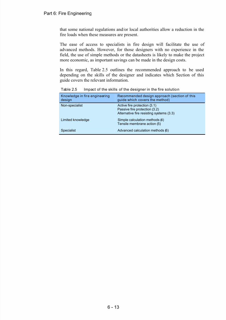
In this regard, Table 2.5 outlines the recommended approach to be useddepending on the skills of the designer and indicates which Section of thisguide covers the relevant information.
Table 2.5 Impact of the skills of the designer in the fire solution
Knowledge in fir e engineeringdesign
Recommended design approach (section of thisguide which covers the method)
Non-specialist Active fire protection ( 3.1)Passive fire protection ( 3.2)
Alternative fire resisting systems ( 3.3)
Limited knowledge Simple calculation methods ( 4)Tensile membrane action ( 5)
Specialist Advanced calculation methods ( 6)

8/13/2019 MSB06 Fire Engineering 2010-03-25
http://slidepdf.com/reader/full/msb06-fire-engineering-2010-03-25 22/66
Part 6: Fire Engineering
6 - 14
3 FIRE PROTECTION SOLUTIONS
3.1 Active fire protectionActive fire protection measures include installation of detectors, alarms andsprinklers, which can detect fire or smoke and suppress the fire at its earlieststage.
These fire protection systems can have a significant influence on the level oflife safety and property protection that can be achieved in a building.Prescriptive regulations usually require detection and alarm systems to beinstalled and these, along with sprinklers, often form an important part of thefire safety strategy in performance-based designs.
3.1.1 Detectors and alarmsAs part of a strategy based on active fire protection measures, a number ofdetectors have to be installed in multi-storey buildings. These devices candetect heat, smoke and flames. Fire alarm systems are designed to alertoccupants of the need to evacuate the building due to a fire outbreak.Figure 3.1 shows a typical detector and alarm device.
Figure 3.1 Fire detector and alarm device
3.1.2 SprinklersSprinklers are devices that automatically suppress a small fire, either on itsignition or shortly after its ignition.
As shown in Figure 3.2, a sprinkler normally has a glass bulb, which contains avolatile liquid and seals the water nozzle. In the event of fire, the heated liquidexpands, breaks the glass bulb and thus activates the sprinkler head.
Sprinklers contribute to both structural fire safety and building property protection. In some countries use of sprinklers in a multi-storey building maylead to a reduction in the required fire resistance period, but this should bechecked with the relevant national regulations.

8/13/2019 MSB06 Fire Engineering 2010-03-25
http://slidepdf.com/reader/full/msb06-fire-engineering-2010-03-25 23/66
Part 6: Fire Engineering
6 - 15
Figure 3.2 Sprink ler and its activati on
3.2 Passive fire protectionThe high temperatures induced in a building by the outbreak of a fire affect allconstruction materials, such that their strength and stiffness is reduced as thetemperature increases. It is often necessary to provide fire protection tostructural members in multi-storey steel buildings in order to delay the loss ofload bearing capacity. Structural members may be insulated by using fire
protection materials, such as boards, sprays and intumescent coatings. The performance of these fire protection materials is tested and assessed inaccordance with EN 13381 [5].
The thickness of protection required in a given building will depend on the fire
protection material selected, the fire resistance period required by national building regulations, the section factor of the member to be protected, and thecritical temperature of the member.
3.2.1 Fire protection methods and materialsThere are two types of passive protection materials, namely non-reactive andreactive. Non-reactive protection materials maintain their properties when theyare exposed to a fire. Boards and sprays are the most common non-reactivematerials. Reactive protection materials are characterised by a change in their
properties when they are subject to fire. The most well known example of thistype of protection is the intumescent coating.
Boards
A variety of proprietary boards, with thicknesses ranging from 15 to 50 mm,are widely used to protect steel members to achieve a 30 to 120 minute fireresistance.
Boards are generally manufactured from either mineral fibres or naturallyoccurring plate-like materials such as vermiculite and mica, using cementand/or silicate binders. Boards may be fixed to steel members eithermechanically, using screws, straps and/or galvanized angles, or glued and
pinned.

8/13/2019 MSB06 Fire Engineering 2010-03-25
http://slidepdf.com/reader/full/msb06-fire-engineering-2010-03-25 24/66
Part 6: Fire Engineering
6 - 16
0
10
20
30
40
50
60
30 60 90 120
Fire resistance (mins)
T h i c k n e s s ( m m )
(a) (b)
Figure 3.3 Board fire protection (a) Fixing of boards to steel column; (b) Fire
resistance
Boards are factory-manufactured and therefore, their thickness and quality cangenerally be guaranteed. They offer a clean, boxed appearance, which may be
pre-finished or ready for further decoration. However, boards cannot easily befitted to members with complex shapes. Boards generally cost more thansprayed and intumescent coatings, although non-decorative boards may becheaper than decorative ones. In addition, the time required to fix the boards issignificant compared to the application of intumescent coatings, which not onlyincreases the construction costs but it also affects the construction programmeof multi-storey buildings.
Sprayed non-reactive coatings
The process of applying this type of protection is shown in Figure 3.4(a).Sprayed non-reactive coatings with thicknesses of 10 to 35 mm are widely usedto protect steel members, to achieve a fire resistance of between 30 and 120minutes, as shown in Figure 3.4(b).
0
5
10
15
20
25
30
35
40
30 60 90 120
Fire resistance (mins)
T h i c k n e s s ( m m
)
(a) Application (b) Fire resistance for a given thickness
Figure 3.4 Sprayed non-reactive fire protection (a) Appl ication (b) Fireresistance

8/13/2019 MSB06 Fire Engineering 2010-03-25
http://slidepdf.com/reader/full/msb06-fire-engineering-2010-03-25 25/66
Part 6: Fire Engineering
6 - 17
Sprayed non-reactive coatings are mainly cement or gypsum based materialsthat contain mineral fibre, expanded vermiculite and/or other lightweightaggregates or fillers. This type of protection is applied in situ and it is
particularly suitable for members that have complex profiles and are not visiblein use. However, spraying the protection in situ may require extensive
shielding and affect the construction programme.
Intumescent coatings
In contrast with the non-reactive boards and sprays, intumescent coatings reactin fire, and change their properties from an initial decorative paint into anintumescent layer of carbonaceous char, by swelling to about 50 times theiroriginal thickness. Typical initial thicknesses of 0,25 to 2,5 mm can provide afire resistance of 30 to 120 minutes, as shown in Figure 3.5.
Intumescent coatings are similar in appearance to conventional paints, and may be solvent based or water borne. They consist of three layers which include acompatible primer, the intumescent coat and a top coat or sealer coat (oftenavailable in a wide range of colours). Currently, most intumescent coatings areapplied off site to aid the construction programme.
0.0
1.0
2.0
3.0
4.0
5.0
30 60 90Fire resistance(mins)
T h i c k n e s s
( m m
)
Figure 3.5 Intumescent coatings
Some intumescent coatings are also used for external applications and forheritage applications, where the appearance of the building must bemaintained.
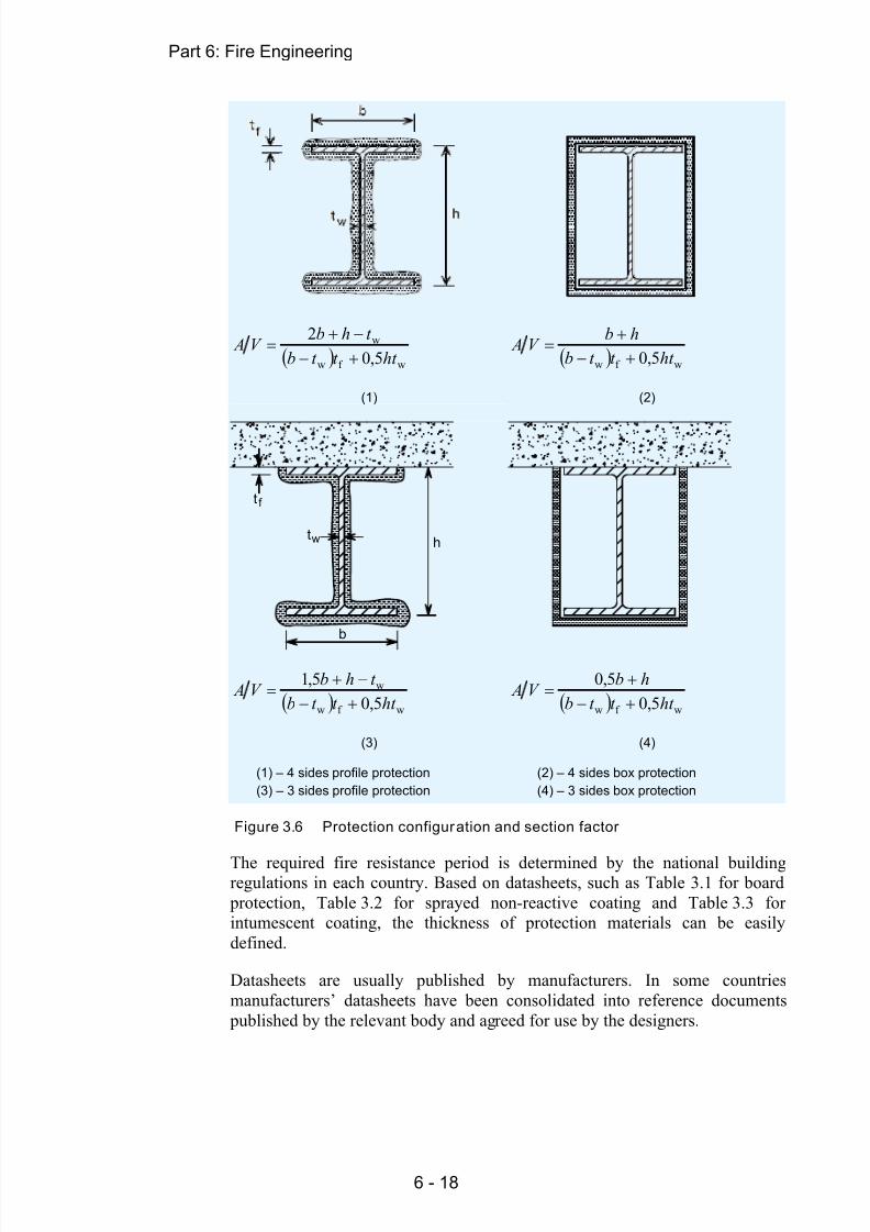
3.2.2 Thickness of fir e protection materialsFor a given product, the thickness of fire protection depends on the requiredfire resistance and on the section factor of the steel members. The sectionfactor varies with the choice of fire protection and with the type and size ofsteel member. Figure 3.6 gives expressions to calculate the section factor,
based on the configuration of fire protection and on the geometric properties ofthe steel section.
8/13/2019 MSB06 Fire Engineering 2010-03-25
http://slidepdf.com/reader/full/msb06-fire-engineering-2010-03-25 26/66
Part 6: Fire Engineering
6 - 18
wf w
w
5,02
ht t t bt hb
V A
(1)
wf w 5,0 ht t t bhb
V A
(2)
b
t
t
w
f
h
wf w
w
5,05,1
ht t t bt hb
V A
(3)
wf w 5,05,0
ht t t bhb
V A
(4)
(1) – 4 sides profile protection (2) – 4 sides box protection(3) – 3 sides profile protection (4) – 3 sides box protection
Figure 3.6 Protection configuration and section factor
The required fire resistance period is determined by the national buildingregulations in each country. Based on datasheets, such as Table 3.1 for board
protection, Table 3.2 for sprayed non-reactive coating and Table 3.3 forintumescent coating, the thickness of protection materials can be easilydefined.
Datasheets are usually published by manufacturers. In some countriesmanufacturers’ datasheets have been consolidated into reference documents
published by the relevant body and agreed for use by the designers.

8/13/2019 MSB06 Fire Engineering 2010-03-25
http://slidepdf.com/reader/full/msb06-fire-engineering-2010-03-25 27/66
Part 6: Fire Engineering
6 - 19
Table 3.1 Example of datasheet for board fire prot ection
Maximum Section factor A m /V (m -1)for beams and colu mns
Thickness of board protection(mm)
R30 R60 R90 R120
20 260 260 125 7025 198 110
30 260 168
35 232
40 256
45 260
Table 3.2 Example of datasheet for sprayed non-reactive coatings
Required thickness (mm) of sprayed non-reactivecoatings
Section factor A m /V (m -1) R30 R60 R90 R120
40 10 10 11 15
80 10 12 16 21
120 10 14 19 24
160 10 15 21 26
200 10 16 22 28
240 10 16 23 29
280 10 17 23 30
Table 3.3 Example of datasheet for intumescent coatings for R60Section factor A m /V (m -1) 3 side- I beam 4 side- I beam 4 side– I column
40 0,25 0,26 0,26
80 0,31 0,39 0,39
120 0,39 0,53 0,53
160 0,48 0,66 0,66
200 0,69 0,83 0,83
240 0,90 1,00 1,00
280 1,08 1,74 1,74
3.3 Fire resisting constructionIn recognition of the importance of structural fire resistance and the costsassociated with passive fire protection materials, some alternative structuralsystems have been developed which utilize their inherent fire resistance andavoid the need of dedicated fire protection. These systems include compositefloors, integrated beams and encased steelwork.
3.3.1 Composi te floorPrecast concrete slabs have an inherent fire resistance of up to 120 minutes if
adequate provision and detailing of rebar is made. However, the slabs usuallyrest on the top flange of a down stand beam (see Figure 3.7(a)), which isexposed on three sides and requires fire protection.

8/13/2019 MSB06 Fire Engineering 2010-03-25
http://slidepdf.com/reader/full/msb06-fire-engineering-2010-03-25 28/66
Part 6: Fire Engineering
6 - 20
As an alternative to precast concrete floors, composite floors, shown inFigure 3.7(b), are popular in multi-storey buildings.
(a) (b)
Figure 3.7 (a) Precast concrete floor on down stand beam; (b) composit efloors wi th steel decking
Composite floors are constructed using either trapezoidal or re-entrant profiledsteel decking that supports the concrete on top. In a composite floor, theconcrete is reinforced using fibre or bar reinforcement to control cracks caused
by the flexural tension at the floor support, and by shrinkage and settlement ofthe concrete. In addition to controlling cracks, the bar reinforcement also
provides the floor with bending resistance at its support in the fire condition.
For a composite floor with the bottom surface exposed, the insulation criterion
is usually satisfied by providing sufficient insulation depth of the concrete forthe required fire resistance period, as shown in Table 3.4. The longer therequired fire resistance period, the thicker the insulation concrete needs to be.The integrity criterion is generally met by using continuous steel decking.
Table 3.4 Typical minimum insulation thickness (mm), h 1, of concrete incomposite floors
Trapezoidal steel decking Re-entrant steel decking
Requi red FireResistance
(minutes)
Normal weightconcrete
Light weightconcrete
Normal w eightconcrete
Light weightconcrete
60 70 60 90 90
90 80 70 110 105
120 90 80 125 115
Table 3.5 shows typical depths and spans of composite floors with normalweight concrete under a uniform applied load of 5,0 kN/mm 2.
h 1
h 2 h2
h 1

8/13/2019 MSB06 Fire Engineering 2010-03-25
http://slidepdf.com/reader/full/msb06-fire-engineering-2010-03-25 29/66
Part 6: Fire Engineering
6 - 21
Table 3.5 Typical depths and spans of composit e floors
Trapezoidal steel decking Re-entrant steel decking
Single span Double span Single span Double span
Required fireResistance(minutes)
Depth(mm)
Span(m)
Depth(mm)
Span(m)
Depth(mm)
Span(m)
Depth(mm)
Span(m)
60 140 3,8 140 4,2 101 3,0 101 3,4
90 150 3,1 150 3,3 105 2,9 105 3,3
120 160 3,1 160 3,4 115 2,4 115 2,9
3.3.2 Integrated beamsIntegrated beams are part of a floor construction system where the steel beamsare contained within the depth of an in-situ or pre-cast concrete slab, instead ofsupporting the slab on the top flanges of the beams. Consequently, the overalldepth of the floor construction is minimized. The whole steel section, exceptfor its bottom flange or plate, is insulated from the fire by the surroundingconcrete.
Figure 3.8 ASB - Integrated beam (rolled asymmetric steel beam)
Figure 3.9 IFB - Integrated beam (I-section with a plate welded to its bot tomflange)
d d

8/13/2019 MSB06 Fire Engineering 2010-03-25
http://slidepdf.com/reader/full/msb06-fire-engineering-2010-03-25 30/66
Part 6: Fire Engineering
6 - 22
There are two types of open section integrated beams: asymmetric steel beam(ASB) and integrated fabricated beam (IFB), as shown in Figure 3.8 andFigure 3.9 respectively.
Generally, integrated beams can achieve up to 60 minutes fire resistance
without being fire-protected. With the inclusion of additional longitudinalreinforcement, 90 minutes fire resistance is possible with an unprotected bottom flange. The total structural depths and typical spans of integrated beamsare summarised in Table 3.6, which may be referred to at the preliminarydesign of multi-storey buildings.
Table 3.6 Struct ural depth and typ ical span of integrated beams
Type of floor Depth (mm) Span (m)
ASB Integrated beam 280 to 400 6 to 9
IFB Integrated beam 250 to 450 6 to 9
3.3.3 Parti ally encased beams and columnsPartially encased beams and columns are constructed by filling the space
between the flanges of I-sections using plain or reinforced concrete, as shownin Figure 3.10 and Figure 3.11.
Compared with the unprotected I-sections, which only have about 15 minutesfire resistance, partially encased sections can achieve over 60 minutes, whichnormally meets the fire resistance requirements of many multi-storey buildings.The increase in fire resistance period is due to the coverage of most parts of thesurface area of the steelwork using concrete, which has a low thermalconductivity. Longer periods of fire resistance can also be achieved byincreasing the amount of reinforcement embedded within the concrete, tocompensate the loss of the strength of the steelwork in fire.
u
u
1e
e
f
h
h
c
c
beff
2w
b
A
A s
f f exb= A
Figure 3.10 Partially encased beam
EN 1994-1-2 offers relatively simple rules and established datasheets in clauses§4.2.2 and §4.2.3 for fire design of composite beams and columns, including
partially encased steel sections. These rules relate the fire resistance of

8/13/2019 MSB06 Fire Engineering 2010-03-25
http://slidepdf.com/reader/full/msb06-fire-engineering-2010-03-25 31/66
Part 6: Fire Engineering
6 - 23
composite members to their load level (the load level is denoted as fi,t and isdescribed in Sections 4.4.2 and 4.4.3 of this guide), the h/b ratio, the membertype and the area of reinforcement As.
Generally, an increase of the fire resistance or the load level requires larger
cross-sections and additional reinforcement for partially encased sections. Thedatasheets can be used to determine the minimum cross-sectional dimensions(such as the section width bmin) and reinforcement ratio As,min of partiallyencased sections, to achieve the required fire resistance period.
c A A
u
u
s
s
e
e
w
b
s
f
h
Figure 3.11 Partially encased column
Table 3.7 shows a datasheet taken from EN 1994-1-2 for the fire design of partially encased sections. When using this type of design data, the load levelηfi,t may be calculated as follows:
dtfi,td,fi, R R
where:
Rfi,d,t is the design resistance of the member in fire conditions at time, t .
Rd is the design resistance of the member for room temperature design.When calculating the load level, EN 1994-1-2 recommends that the designresistance for room temperature design, Rd, is calculated for a buckling lengththat is twice the buckling length used for fire design.

8/13/2019 MSB06 Fire Engineering 2010-03-25
http://slidepdf.com/reader/full/msb06-fire-engineering-2010-03-25 32/66
Part 6: Fire Engineering
6 - 24
Table 3.7 Typical datasheets for fire design of partially encased sections
Width b min (mm)/Reinforcement A s,min ratio (%) forthe required fi re resistance period (min)Member
SectionRatio
h /b Load level
R30 R60 R90 R120 R180
fi,t ≤ 0,5 80/0,0 150/0,0 200/0,2 240/0,3 300/0,5>1,5
fi,t ≤ 0,7 80/0,0 240/0,3 270/0,4 300/0,6
fi,t ≤ 0,5 60/0,0 100/0,0 170/0,2 200/0,3 250/0,3
Beam
>3,0
fi,t ≤ 0,7 70/0,0 170/0,2 190/0,4 270/0,5 300/0,8
fi,t ≤ 0,47 160/- 300/4,0 400/4,0Column Minimumh and b
fi,t ≤ 0,66 160/1,0 400/4,0
As an example, consider the case of a partially-encased beam with a ratioh/b > 3, under moderate load ( fi,t ≤ 0,5).
For a fire resistance period of 60 minutes (R60):
The width should not be less than 100 mm, which leads toh > 3 b = 300 mm. So the minimum cross-sectional area is 100 300 mm
No reinforcement is required, As = 0.
To achieve a fire resistance period of 120 minutes (R120):
The width should not be less than 200 mm. Therefore the heighth > 3 b = 600 mm and therefore the minimum cross-sectional area is200 600 mm
The reinforcement area, As, should not be less than 0,3% of the encasedconcrete area Ac, i.e. , As ≥ 0,003 Ac.
3.3.4 External steelworkIn some circumstances, the main structural members, such as columns and
beams, may be located outside the building envelope without any fire protection, as shown in Figure 3.12. The fire protection requirements ofexternal steelwork are significantly reduced, as the temperature of the externalsteelwork is lower compared to members inside a compartment.
Further guidance on use of external steelwork for fire design can be found inEN 1993-1-2, §4.2.5.4.

8/13/2019 MSB06 Fire Engineering 2010-03-25
http://slidepdf.com/reader/full/msb06-fire-engineering-2010-03-25 33/66
Part 6: Fire Engineering
6 - 25
Figure 3.12 Use of external steelwork
3.3.5 Combined solu tions for fir e resistanceBy careful selection of the structural solutions, up to 60 minutes of fireresistance can be achieved for multi-storey buildings without applying fire
protection materials. Generally, this will demand the use of integrated beamsand partially encased or concrete filled columns. Table 3.8 shows the fireresistance period that may be achieved for a structure using combinations of
beam and column construction discussed above. This table considers the fireresistance of individual elements and less conservative results can generally beachieved by considering fire design based on assemblies of structural elements
using methods such as FRACOF (see Section 5.2).
Table 3.8 Combined solution for steel frame with or without fire protection
Unprotectedbeam
Externalbeam
Integratedbeams
Encasedbeam
Protectedbeam
Fire resistance period (min)
Unprotected steel column 15 15 15 15 15
External column 15 >30 >30 >30 >30
Encased column 15 >30 >60 >60 >60
Protected column 15 >30 >60 >60 >60
Note: Fire resistance period stated is the lower value for the beam or column construction.

8/13/2019 MSB06 Fire Engineering 2010-03-25
http://slidepdf.com/reader/full/msb06-fire-engineering-2010-03-25 34/66
Part 6: Fire Engineering
6 - 26
4 SIMPLE CALCULATION MODELS
In previous Sections, the prescriptive approach to fire design through use of
datasheets has been shown to provide a safe solution. However, it does notnecessarily offer the most efficient design. By using the simple calculationmodels described in the Eurocodes, the designer may be able to demonstratethat less or no protection is required in some or all of the structural elements,thus leading to a more economic solution to fire design.
There are two approaches to these simple calculations: the critical temperatureapproach and the load bearing capacity approach. Based on these methods thedesigner may reasonably decide whether or not fire-protection is required.
These methods, however, deal with individual members under standard fireexposure, instead of an entire structure in natural fire. Hence, unlike the
performance-based analysis (see Section 6), they do not consider the actual behaviour of the structural member in a real fire.
In order facilitate the understanding of the reasoning behind the simplemethods given in the Eurocode and described in Sections 4.4.2 and 4.4.3 of thisguide, an introduction to the thermal effects of fire is given in Section 4.1.
4.1 Fire behaviour and thermal actions4.1.1 Fire action and standard fir e
Fire is a very complex phenomenon that involves different kinds of chemicalreactions. Fire releases heat energy in the form of flames and smoke within the
building compartment, as shown in Figure 4.1 (a).
When a fire occurs, the temperature of the gas within the building compartmentrises rapidly. For the purpose of fire design, the fire action is represented by astandard temperature-time curve, as defined in EN 1991-1-2. This curve isdenoted ‘standard fire’ in Figure 4.1(b).
(a) Fire (Cardington test) ( b) Standard fire curve and temperature rise of members
Figure 4.1 Fire action

8/13/2019 MSB06 Fire Engineering 2010-03-25
http://slidepdf.com/reader/full/msb06-fire-engineering-2010-03-25 35/66
Part 6: Fire Engineering
6 - 27
The temperature rise of a member in fire is predominantly governed byradiation and convection mechanisms, via a complex diffusion process. Itdepends on the thermal properties of the materials and the thickness of the
protection layer, if it is fire-protected.
Due to the rapid increase of the gas temperature, the heat energy from the fire(i.e . thermal action) flows into the member through the exposed surfaces, andheats up the member. As a result, the temperature of the member rises,typically following the curves shown in Figure 4.1 (b) for different scenarios of
protected and unprotected members.
4.1.2 Modelling fir e behaviourAs a thermal action on building structures, a fire can be classified into localisedand fully-developed fires.
Localised fire
A localised fire is in the pre-flashover phase and occurs only in some part of acompartment. A localised fire is unlikely to spread to the whole compartmentand to cause a flashover, due to its slow propagation and the low temperaturedeveloped. A localised fire is generally modelled using plume, zones andcomputational fluid dynamics (CFD) models.
Plume model
Annex C of EN 1991-1-2 gives a so-called plume model to determine thethermal action of a localised fire. If the flame remains below the ceiling, asshown in Figure 4.2 (a), the model is used to calculate the correspondingtemperature along its vertical axis. However, if the flame impacts the ceiling,as shown in Figure 4.2 (b) then the model determines the heat flux at the levelof the ceiling together with the flame length.
a) Flame remains below the ceiling (b) Flame impacts the ceiling
Figure 4.2 Plume model for a locali sed fire in EN 1991-1-2
4.1.3 Fully developed fir eA fire is fully developed when all the available fuels within a compartment are
burning simultaneously and the maximum heat is released. A fully developedfire is commonly modelled using either standard or parametric fires, as shown

8/13/2019 MSB06 Fire Engineering 2010-03-25
http://slidepdf.com/reader/full/msb06-fire-engineering-2010-03-25 36/66
Part 6: Fire Engineering
6 - 28
in Figure 4.3. The severity of a fully developed fire is governed by theventilation condition and quantity and nature of the fuel within thecompartment.
Standard Fire
Parametric fire
0
200
400
600
800
1000
1200
0 30 60 90 120 150 180
Time (min)
Gas Temperature (°C)
Figure 4.3 Model of ful ly developed fire
4.1.4 Nominal temperature-time curveStandard fire
EN 1991-1-2, §3.2 uses the standard temperature-time curve to represent thethermal action of a fully developed fire. This ‘standard fire’ is used to classifythe fire performance of the structural materials and members in standard firefurnace tests. It forms the basis on which the fire resistance time and load
bearing resistance of structural members are evaluated using the simplecalculation models from EN 1993-1-2 and EN 1994-1-2. It is also used in the
performance-based analysis for fire design of a whole structure.
4.1.5 Natural fi re modelParametric fire
EN 1991-1-2, Annex A defines a parametric temperature-time curve for firecompartments up to 500 m 2 floor area. This ‘parametric fire’ consists of a
heating, cooling and residual phases. The heating phase is normally representedusing an exponential curve up to a maximum temperature. The cooling phase isdescribed by a sloping straight line until it reaches the residual phase. For a
parametric fire, the heating phase depends on ventilation conditions and thethermal properties of the compartment boundary. The heating duration andmaximum temperature are governed by the density of the fire loads and theventilation condition. The cooling phase is controlled by the heating durationand the maximum temperature that has been reached.
To some extent, the parametric fire represents the characteristics of a naturalfire. However, its accuracy for estimating the thermal response of fire dependson the accuracy of the input data, such as fire load, ventilation condition,compartment size and thermal properties of the boundary condition.

8/13/2019 MSB06 Fire Engineering 2010-03-25
http://slidepdf.com/reader/full/msb06-fire-engineering-2010-03-25 37/66
Part 6: Fire Engineering
6 - 29
4.2 Heat transferThis Section explains the fire actions and the evolution of the temperature instructural members under a standard fire exposure, with an emphasis on theconcepts of standard fire and section factor.
Section factor A m /V
An important parameter in the rate at which the temperature of a memberincreases is the ratio Am/V of the member, commonly known as the sectionfactor. The section factor is defined as the ratio of the exposed surface area of amember to its volume per unit length.
The influence of the section factor is shown in Figure 4.1(b) for protected andunprotected members. A larger section factor leads to a faster heating of themember. For example, after 15 minutes of fire exposure, the temperature of anunprotected member with a section factor of Am/V = 200 increases to about
580 C, while that of the unprotected member with Am /V = 100 only reaches380 C.
This difference is due to the fact that a large value of the section factorrepresents a large exposed surface area compared with its volume, andtherefore, the member receives more heat than that with a low section factor,which represents a small exposed surface area. This is illustrated in Figure 4.4.
Figure 4.4 Definition of section factor A m /V of a member in fire
Member temperature at time t
The temperature θ a,t of the member at time t can be calculated using the simplemodels given in §4.2.5 of EN 1993-1-2 or §4.3.4.2 of EN 1994-1-2.
If the critical temperature exceeds the design temperature, i.e . θ cr > θ a,t then thefire resistance of the unprotected member is adequate for that duration.

8/13/2019 MSB06 Fire Engineering 2010-03-25
http://slidepdf.com/reader/full/msb06-fire-engineering-2010-03-25 38/66
Part 6: Fire Engineering
6 - 30
If the unprotected member is not adequate, measures have to be taken toimprove its fire resistance by:
Choosing a larger cross-section for the steel member
Selecting a higher grade of steel
Providing the necessary fire protection.
4.3 Structural AnalysisFigure 4.5 illustrates the general behaviour of a structural member under theeffect of the standard fire and applied actions. As the gas temperature θ g rises,the member temperature θ a,t increases and its load bearing resistance Rfi,d,t decreases.
The critical temperature θ cr is defined as the temperature at which a member
can no longer support the design effects of the applied actions. The effects ofactions (also called action effects) on a member are the internal forces ormoments induced by the actions. For example the wind blowing on a structureis an action (the wind action) and the internal forces and bending momentsinduced in a column are the effects.
Given a structure subject to various actions (e.g. wind, gravity), a member issubject to the design value of an effect, E d. Under the same actions but alsosubject to fire, the effects on the member are modified, and denoted as E fi,d .
The critical temperature θ cr is therefore defined as the temperature at the time
of failure, when the resistance of a member is equal to the effect on it: Rfi,d,t = E fi,d .
Figure 4.5 Behaviour of a structural member in fire
Member temperature θ a,t
Gas temperature θ g Member resistance Rfi,d,t
Load resistance Temperature
t fi,dt requ Time
Effect offire action
E fi,d
Criticaltemperatureθ cr

8/13/2019 MSB06 Fire Engineering 2010-03-25
http://slidepdf.com/reader/full/msb06-fire-engineering-2010-03-25 39/66
Part 6: Fire Engineering
6 - 31
To meet the requirements of fire safety engineering, the designer must ensurethat one of the following conditions is met:
At t fi,requ the temperature of the member is lower than the criticaltemperature: θ cr ≥ θ a,t or
At t fi,requ the resistance of the members is greater than the design effects: Rfi,d,t ≥ E fi,d.
4.4 Simple structural fire design methods4.4.1 Introduction
The simple design methods follow the principle of ultimate limit design as fornormal temperature. Fire safety requirements are satisfied by providing adesign which will meet the above conditions.
Simple calculation models take account of the reduction of the action effectsfor fire design and the variation of material properties at elevated temperature.The simple calculation models have broader application than the prescriptiveapproach, and can be applied to:
Unprotected steel members, including tension members, steel beams andsteel columns.
Unprotected composite members, including composite slabs and beams,concrete encased beams and columns, concrete filled hollow columns.
Protected steel and composite members.
Design effect of actions, E fi,d The fire action is designated as an accidental action in the fire parts ofEurocodes. Due to the low probability of both a major fire and full externalactions occurring simultaneously, the effect of actions for fire design can bedetermined by reducing the design effects of external actions for normal designusing a reduction factor fi:
E fi,d = fi E d
where:
E d is the design effect of actions for normal design using EN 1990
fi is the reduction factor of the effect E d for fire design, calculated as
fi =k,1Q,1k G
k,1fik
QG
QG
for combination 6.10 from EN 1990
Gk is the characteristic value of the permanent action
Qk,1 is the characteristic value of the leading variable action
fi is the combination factor given by 1,1 or 2,1, see EN 1991-1-2
G is the partial factor for permanent actions
Q,1 is the partial factor for the leading variable action.For the calculation of the reduction factor for use with combination 6.10a and6.10b, the designer should refer to EN 1993-1-2 §2.4.2.

8/13/2019 MSB06 Fire Engineering 2010-03-25
http://slidepdf.com/reader/full/msb06-fire-engineering-2010-03-25 40/66
Part 6: Fire Engineering
6 - 32
4.4.2 Critical temperature approachThe basis for this approach is to calculate the temperature of the member afterthe required period of fire resistance and to compare it to the criticaltemperature, at which the member would collapse. The steps that must befollowed to apply the critical temperature approach are shown in Figure 4.6.
Selection ofprotected orunprotected
member
Calculateresistance for
Normal design, Rd
(M, N and V)
Rd > E d ?
Calculate membertemperature θ a,t at
tf i,requ
θ cr > θ a,t ?
Appropriate design
Addprotection
Calculate criticaltemperature, θ cr
Degree ofutilisation, fi
tfi,requ
Am / V
Design effect, Ed
Yes
No
Yes
No
EN 1993
EN 1993-1-2, §4.2.5EN 1994-1-2, §4.3.4.2
EN 1993-1-2, §2.4.2
EN 1993-1-2, §4.2.4
EN 1993-1-2, Tables4.2 and 4.3
National regulations
Figure 4.6 Fire design of members using the cri tical temperature approach
Critical temperature
The simple model with the critical temperature approach can only be used forindividual members, when their deformation criteria or stability considerationsdo not have to be taken into account. This approach is only permitted for

8/13/2019 MSB06 Fire Engineering 2010-03-25
http://slidepdf.com/reader/full/msb06-fire-engineering-2010-03-25 41/66
Part 6: Fire Engineering
6 - 33
tension members and for restrained beams, but not for unrestrained beams andcolumns when buckling is a potential failure mode.
The critical temperature of a non-composite steel member can be calculatedusing the simple model given in §4.2.4 of EN 1993-1-2. The critical
temperature decreases with the degree of utilisation of the member, μ0, which isdefined as the ratio of the design effect of actions at elevated temperature, E fi,d ,to the member resistance at normal temperature but using partial factors for firedesign Rfi,d,0 such that:
μ0 = E fi,d/ Rfi,d,0
For Class 4 sections, a critical temperature of 350°C is recommended.
The critical temperature of composite members is given by §4.3.4.2.3 ofEN 1994-1-2.
4.4.3 Load bearing capacity approachThe basis for this approach is to calculate the resistance of the member after therequired period of fire resistance and to compare it to the design effect of theactions at elevated temperature, E d,fi. The steps that must be followed to applythe load bearing capacity approach are shown in Figure 4.7.
Section classification
As for normal temperature design, cross-sections are classified according toTable 5.2 from EN 1993-1-1.
The coefficient is modified by applying a 0,85 factor, in order to account forthe reduction in yield strength and elastic modulus of the steel at elevatedtemperatures, as specified in §4.2.2 of EN 1993-1-2. This modification lowersthe c/t limits for the various section classes, so some sections may have a moreonerous classification than for normal design.
Tension, shear and bending resis tance of steel members in f ire
The simple models to calculate the design tension, shear and bendingresistances of steel members under standard fire are given in §4.2.3.1, §4.2.3.3and §4.2.3.4 of EN 1993-1-2.
These models are based on the assumption that the members have a uniformtemperature throughout, and make use of a reduced yield strength and therelevant partial factors for fire design.
However, in reality the temperature across and along a member is hardly everuniform, which affects its mechanical behaviour. For example, if a steel beamsupports a concrete slab on its upper flange, the temperature in the top flange islower than in the bottom flange and therefore its ultimate moment resistance ishigher than for a uniform temperature equal to that of the bottom flange.

8/13/2019 MSB06 Fire Engineering 2010-03-25
http://slidepdf.com/reader/full/msb06-fire-engineering-2010-03-25 42/66
Part 6: Fire Engineering
6 - 34
Selection ofprotected orunprotected
member
Calculateresistance for
Normal design, Rd
(M, N and V)
Rd > E d ?
Calculate memberresistance R fi,d at
tfi,requ
R fi,d > E fi,d ?
Appropriate design
Addprotection
Calculate effect ofactions in fire, E fi,d
Degree ofutilisation, fi
tfi,requ
Am / V
Design effect, E d
Yes
No
Yes
No
EN 1993
EN 1993-1-2, §4.2.3EN 1994-1-2, §4.3.4.1
EN 1993-1-2, §2.4.2
EN 1993-1-2, §2.4.2
EN 1993-1-2, Tables4.2 and 4.3
National regulations
Figure 4.7 Fire design of members using the load bearing capacity approach
The benefits from such thermal gradient can be taken into account by dividingthe cross-section into a number of elements and allocating a reduced yieldstrength to each element according to their temperature. The total resistance ofthe cross-section can be calculated by adding up the resistances of eachelement. Alternatively, the beneficial influence of thermal gradient on theresistance of these members can be calculated conservatively using twoempirical adaptation factors, 1 and 2, as given in §4.2.3.3 of EN 1993-1-2.

8/13/2019 MSB06 Fire Engineering 2010-03-25
http://slidepdf.com/reader/full/msb06-fire-engineering-2010-03-25 43/66
Part 6: Fire Engineering
6 - 35
Resistances of unrestrained beams and columns
The simple models for calculating the buckling resistances of unrestrained beams and columns with a uniform temperature are given in §4.2.3.3, §4.2.3.4and §4.2.3.2 of EN 1993-1-2. These rules were developed by imposing thefollowing modifications on the relevant models given in EN 1993-1-1 fornormal design to account for the effect of elevated temperature: Reduced yield strength for elevated temperature
Use of partial factors for fire design
Increased non-dimensional slenderness
Buckling length of columns in fire is taken as 0,5 and 0,7 of the systemlength for the top storey and for the other storeys, respectively
Specific buckling curves for the fire condition.
Resistance of composite members in fireThe simple models to calculate the resistances of composite members in fireare given in §4.3 and Annexes D, E, F, G and H of EN 1994-1-2 for compositeslabs, composite beams, encased beams, encased columns and filled columns.
Since the temperature generally is not uniformly distributed over thecross-section, the design resistance of a composite member in fire generally hasto be calculated by dividing the section into a number of elements. Thetemperature and the corresponding reduction factors for steel and concretestrengths in each element are determined and the design resistance of all theelements are added to calculate the resistance of the entire cross-section.
The simple models for composite members are more complex than thecalculation for bare steel members. For this reason, most calculations fortemperature rise and load bearing resistance of composite members are carriedout using computer software. In addition, the resistances of many fire designsolutions for composite members have been tabulated, as given in §4.2 ofEN 1994-1-2.
Resistance of composite slabs
The simple models for fire design of composite slabs are specified in §4.3.1,§4.3.2 and §4.3.3 of EN 1994-1-2. As partition members, composite slabs arerequired to meet the criteria of insulation ‘ I ’, integrity ‘ E ’ and the load bearingresistance ‘ R’. These must be demonstrated through fire tests, designcalculations or both.
The calculation of sagging and hogging moment resistances of slabs are basedon different assumptions and temperature distributions as given in D.2 and D.3of EN 1994-1-2. The contribution of the steel decking is generally included inthe calculation of the sagging moment resistance, but conservatively ignored inthe calculation of the hogging moment resistance.
Resistance of compos ite beams
Composite beams comprise steel sections structurally attached through shearconnectors to a concrete or composite slab, with or without concreteencasement. Generally, the voids created by the deck shape over the beam

8/13/2019 MSB06 Fire Engineering 2010-03-25
http://slidepdf.com/reader/full/msb06-fire-engineering-2010-03-25 44/66
Part 6: Fire Engineering
6 - 36
flanges are filled, to ensure that the top flange of the steel beam remainsrelatively cool in fire.
Composite beams may be simply supported or continuous. Their designsagging and hogging moment resistances as well as their vertical and
longitudinal shear resistances can be determined by using the simple modelsgiven in §4.3.1, §4.3.4 and Annex E of EN 1994-1-2.
Resistance of composite columns
The simple model for buckling resistance of composite columns is based on theassumption that the building is braced and the column has no horizontaldisplacement. The calculation rules are given in §4.3.5 and Annexes G and Hof EN 1994-1-2.

8/13/2019 MSB06 Fire Engineering 2010-03-25
http://slidepdf.com/reader/full/msb06-fire-engineering-2010-03-25 45/66
Part 6: Fire Engineering
6 - 37
5 TENSILE MEMBRANE ACTION
Full scale fire tests and real fire investigations in multi storey buildings have
shown that when a floor develops tensile membrane action, it can achieve ahigher fire resistance than calculations and tests on isolated members indicate.In order to take account of this beneficial behaviour of multi-storey buildingsin fire, a new design model has been developed, which allows for a moreeconomic solution to fire design. The model has been validated by tests.
5.1 Cardington fire testThe prescriptive approach and the simple calculation models described in thisguide are well-established methods to carry out the fire design of a multi-storey
building.
The application of such methods to an unprotected multi-storey steel buildingdetermines the fire resistance period as no more than 30 minutes. However,large-scale fire tests and real fire investigations over the years havedemonstrated that some savings can be achieved in the fire design of the frame,and a new simple design method (BRE-BM) has been developed.
5.1.1 Full -scale fi re testsFollowing the investigations on real fire-damaged buildings in the UK atBroadgate and Basingstoke, fire tests were conducted in Cardington (UK) on afull-scale eight-storey steel-composite framed building with unprotected steel
beams and trapezoidal composite slab, as shown in Figure 5.1(a).
0 50 100 150 200 250 300 3500
100
200
300
400
500
600
0
200
400
600
800
1000
1200
Time (mins)
M a x i m u m
v e r t i c a
l d i s p l a c e m e n
t ( m m
)
M a x i m u m
s t e e
l t e m p e r a
t u r e
( ° C )
Maximum vertical displacement Maximum temperature
(a) Full-scale building tested inCardington
(b) Temperature and displacement of secondary beam
Figure 5.1 Cardington fire tests
Observations from the tests and the real fire investigations have consistentlyshown that the performance of a whole steel-framed building in fire is verydifferent from that of its individual members. Under applied actions and a realfire, significant interactions between different types of structural members andimportant changes of their load-carrying mechanisms take place in realstructures. The inherent fire performance of unprotected steel elements in

8/13/2019 MSB06 Fire Engineering 2010-03-25
http://slidepdf.com/reader/full/msb06-fire-engineering-2010-03-25 46/66
Part 6: Fire Engineering
6 - 38
framed buildings, even in severe fires, is much better than standard fire testswould demonstrate.
As shown in Figure 5.1(b), instead of full collapse, as expected from thestandard fire tests, a typical secondary beam in the Cardington fire test
maintained its stability even when its temperature reached 954 C. Its verticaldisplacement reached 428 mm at its peak temperature of 954 C and recoveredto a permanent displacement of 296 mm after the cooling phase. This indicatesthat there are large reserves of fire resistance in steel-framed buildings. Theamount of fire protection being applied to steel elements may, in some cases,
be excessive and unnecessary.
The main reason for the above large reserves of fire resistance of multi-storeyframed buildings comes from the tensile membrane action of theirsteel-composite floors, as shown in Figure 5.2 and explained below.
Figure 5.2 Membrane action in a horizontally restrained conc rete slab
As described in the Section 4, the simple calculation models for fire designdeal with each individual member. These simple models assume the floor slabto be a one-way spanning beam, resisting actions through bending and shear.Observations of the Cardington tests, however, show that as the steel beamslose their load bearing capacity, the composite slab utilises its full bendingcapacity in spanning between the adjacent, cooler members. As itsdisplacement increases, the slab acts as a tensile membrane, carrying loads intension, as shown in Figure 5.3.
If the slab is well supported against its vertical deflection along lines whichdivide it into reasonably square areas, for example, by the primary andsecondary beams on the column grid-lines, then tensile membrane action can
be generated as a load bearing mechanism. The slab is then forced into double-curvature and hangs as a tensile membrane in its middle regions. A peripheralcompressive ‘ring-beam’ is generated either around its supported periphery orin its edge-beams, as shown in Figure 5.2.
Compression
Compression
zone (‘ring’)
zone (‘ring’)
Tension zone
Tension zone

8/13/2019 MSB06 Fire Engineering 2010-03-25
http://slidepdf.com/reader/full/msb06-fire-engineering-2010-03-25 47/66
Part 6: Fire Engineering
6 - 39
Heated beam
Figure 5.3 Slab bridging by tensil e membrane action
This forms a self-equilibrating mechanism and supports the slab loading. If thetemperature continues to increase, the structure may collapse due to either thefailure of the edge support of the slab, or the fracture of the slab at its edges, orwithin its middle region.
5.1.2 Real fir es compared with standard fir eIn addition to the difference between the behaviour of isolated members andthe members in a whole structure, real fires are also different from the standard
fire that is used in the simple calculation models. A real fire in a buildingcomprises three phases – initial growth, full development and post-peak decay.These phases are shown in Figure 5.4. The temperature increases most rapidlywhen all organic materials in the compartment combust spontaneously. This
point in time is known as flashover point. The growth and decay phases of areal fire depend on the quantity and type of fuel available, as well as on theventilation conditions of the compartment.
Flashover
Standard fire
Natural fire
Startfire Time
T e m p e r a t u r e ( ° C )
Figure 5.4 Real natural fire wi th the standard fire curve
The fire resistance time for a member, which is based on standard fire tests andsimple calculation models, does not reflect the actual fire performance of themember as part of the whole building in a real fire. It does not indicate theactual time for which the member will survive in a building in fire.
5.2 FRACOF fire testsTo demonstrate the actual behaviour and load bearing resistance of compositefloors under standard fire exposure, full scale fire tests were carried out inMaizienes-les-Metz (France) in 2008 as part of the FRACOF project, whichwas funded by ArcelorMittal and the Steel Alliance.
Figure 5.5 shows the composite floor, with an occupying area of more than60 m² and the bottom surface exposed. All structural members of the composite

8/13/2019 MSB06 Fire Engineering 2010-03-25
http://slidepdf.com/reader/full/msb06-fire-engineering-2010-03-25 48/66
Part 6: Fire Engineering
6 - 40
floor were designed in accordance with the relevant Eurocodes for normaldesign. The floor was uniformly loaded using sand bags. The four steelcolumns and four boundary beams were fire-protected, but the twointermediate secondary beams were left unprotected.
Figure 5.5 Details of full-scale fire tests on composit e floo r used in FRACOF
0
200
400
600
800
1000
1200
0 15 30 45 60 75 90 105 120 135 150
Time (min)
T e m p e r a t u r e
( ° C )
CB
A
Test
A
B
C
(a) Temperature of secondary beam
0
50
100
150
200
250
300
350
400
450
500
0 15 30 45 60 75 90 105 120 135 150Time (min)
V e r t i c a
l d i s p
l a c e m e n t
( m m
) Central part ofthe floor
Mid-span of unprotectedcentral secondary beams
Mid-span of protectededge secondary beams
Mid-span of protectedprimary beams
(b) Vertical displacements of the floor
Figure 5.6 Results of full-scale fire tests on composit e floors
As shown in Figure 5.6, under the standard fire and applied loads, even whenthe temperature of the unprotected beam rose to 1040°C and the centraldeflection increased to 448 mm, the composite floor construction maintainedits structural stability for more than 120 minutes. This demonstrates that thefire resistance of composite floors with unprotected secondary beams is much
better than the 15 minutes predicted by standard fire tests.
5.2.1 Design conceptsBased on the full-scale fire tests results and real fire observations, a new designconcept has been developed to assess the fire performance of multi-storey steelframed buildings with composite floors.

8/13/2019 MSB06 Fire Engineering 2010-03-25
http://slidepdf.com/reader/full/msb06-fire-engineering-2010-03-25 49/66
Part 6: Fire Engineering
6 - 41
5.2.2 Design modelsThis model uses a holistic, rather than an elemental approach. It calculates theresidual strength of the composite floors using yield line and membrane action,as shown in Figure 5.7.
Figure 5.7 Yield line and membrane action of a composi te floor in fire
This design model takes account of the interaction between the components ofthe composite floor, and concludes that some beams may remain unprotectedwhilst maintaining the required level of fire safety. Thus, this design modelgives a more economic and site-specific fire safety solution, with a significantnumber of steel beams of the composite floor left unprotected.
This design model was calibrated against the fire tests, and is complemented bydesign tables and computer software. However, it demands expertiseknowledge for the fire design of multi-storey buildings. Further information
can be found in SCI publication P388 [6]
.
5.2.3 ApplicabilityThe FRACOF design model may only be used to demonstrate the fireresistance of a partially protected structure where national building regulations
permit the use of performance-based approach for fire design of buildings. Inaddition, this design model is only applicable to composite steel-framed
buildings with the following limitations.
The frame is braced and not sensitive to buckling in a sway mode
Composite floor slabs comprise steel decking and reinforced concrete
Floor beams are designed to act compositely with the floor slab
This model may not be used with precast concrete floor systems.
Vertical supportto edges of slab

8/13/2019 MSB06 Fire Engineering 2010-03-25
http://slidepdf.com/reader/full/msb06-fire-engineering-2010-03-25 50/66
Part 6: Fire Engineering
6 - 42
6 USE OF NATURAL FIRE EXPOSURE AND ADVANCED STRUCTURAL MODELLING
This Section introduces advanced calculation models that are used todemonstrate the actual behaviour of multi-storey buildings in fire and toexplore more economic solutions for their fire design.
6.1 GeneralTo date, both the datasheet approach and the simple calculation models have
been widely used in the fire design of multi-storey buildings. They have beenshown to be adequate for the minimum life-safety requirements. However, theydo not account for the features of a real fire and the interaction between
structural members in a fire. In addition, increasing innovation in design,construction and usage of modern buildings have made it difficult in somesituations to satisfy the legislative fire regulations economically using thesimple calculation models. Therefore, advanced calculation models have beendeveloped for fire design of multi-storey buildings.
The advanced calculation models are based on the fundamental physicaldescription of fire development, heat transfer and the structural response,which are simulated using numerical models. Therefore, they are able to give amore realistic and economic solution for the fire design of a structure. Theadvanced calculation models may be used to represent the behaviour of
individual members, the whole structure or its sub-assemblies. They allow anappreciation of how buildings actually behave in a fire and give the option todesign a more robust building.
Performance-based design involves establishing performance criteria, definingfire actions, modelling heat transfer and simulating the structural response tothe subsequently derived elevated temperatures, as briefly described below.
6.2 Modelling fire severity6.2.1 Two-zone model
Annex D of EN 1991-1-2 gives a two-zone model to determine the temperaturecaused by a localised fire. It assumes that combustion products within acompartment are accumulated in a layer beneath the ceiling. It divides thewhole compartment with different fire conditions into a number of separatedzones. Within each zone, the fire condition is assumed to be uniform, and thegas temperature is defined as a function of time by considering theconservation of mass and energy in the fire compartment. In each zone, therelevant differential equations are solved for the value of the temperature, usingcomputer software.
6.2.2 Computational flu id dynamics (CFD)Annex D of EN 1991-1-2 proposes a computational fluid dynamic model(CFD) for a localised fire. CFD involves fluid flow, heat transfer and

8/13/2019 MSB06 Fire Engineering 2010-03-25
http://slidepdf.com/reader/full/msb06-fire-engineering-2010-03-25 51/66
Part 6: Fire Engineering
6 - 43
associated phenomena. It uses a series of partial differential equations todetermine the temperature within the compartment due to a localised fire. TheCFD model is very demanding and requires expertise to define the input
parameters and to assess the appropriateness of the results.
6.2.3 Fully developed fir eThe definition of the fully developed fire is given in Section 4.1.3, where thedescription of the standard fire and the parametric fire are also given. Thesefire curves are applicable to advanced models as well as to simple methods.
6.3 Modelling heat transferThe temperature rise of a structural member in fire is due to the heat transferfrom the gas in the compartment to the member. The temperature rise of astructural member in fire is predominantly controlled by radiation and
convection.Advanced models aim to provide a more realistic solution of temperature riseover the section of a structural member. Advanced models consider:
Thermal actions given in EN 1991-1-2
Non-uniform thermal exposure
Non-uniform heat transfer
Time-dependant boundary conditions
Time and temperature-dependant material properties.
Advanced heat transfer models are developed based on 2D or 3D finitedifference or finite element techniques. Therefore, they can only be performed
by using commercial computer software packages.
6.4 Advanced structural modelsAdvanced models for structural responses to both the thermal actions and theapplied actions are based on the fundamentals of structural engineering andcarried out by means of finite element techniques.
The structure under consideration is generally divided into numerous small 2Dor 3D elements with different initial and boundary conditions. Although finiteelement simulation clearly presents significant information to the designer,such an approach should not be taken without due care. There are potential
problems associated with:
The choice of software
The options set within the software
The way the structure is modelled
The acceptance criteria used.

8/13/2019 MSB06 Fire Engineering 2010-03-25
http://slidepdf.com/reader/full/msb06-fire-engineering-2010-03-25 52/66
Part 6: Fire Engineering
6 - 44
6.5 Validation/verification of advanced modelsSince a number of advanced calculation models are available to model fireaction as well as the thermal and structural response of buildings, bothvalidation and verification must be performed to ensure that a sensible solutionis obtained.
Validation is the demonstration of the suitability of the design model orapproach for the intended purpose, which includes those for predictions of fireseverity, heat transfer and structural response.
Verification is the assessment of whether or not the design model has producedvalid results. It includes a careful check on the input data, on the consistence
between the results obtained from the model and the results anticipated onqualitative analysis, and on the degrees of risk associated with possible errors.Advanced models should be verified against relevant test results and othercalculation methods. They should be checked for compliance with normalengineering principles by the use of sensitivity studies.
In the context of validation and verification of models and results, the standardISO 16730 [7] provides a framework for assessment, verification and validationof all types of calculation methods used as tools for fire safety engineering.This international standard does not address specific fire models, but isintended to be applicable to both simple methods and advanced methods.
6.6 Regulatory approvalThe complexity of obtaining regulatory approval will vary from country tocountry. However, regulatory bodies may require the designer to present a firedesign in a form that may be easily checked by a third party, with each designstep clearly documented, including any assumptions and approximations thathave been made. A checklist should be produced that covers the overall designapproach, the fire model, the heat transfer and the structural response.

8/13/2019 MSB06 Fire Engineering 2010-03-25
http://slidepdf.com/reader/full/msb06-fire-engineering-2010-03-25 53/66
Part 6: Fire Engineering
6 - 45
REFERENCES1. Council directive of 21 Dec 1988, On the approximation of laws,
regulations and administrative provisions of the member states relating toconstruction products, 89/106/EEC .
2. EN 1991-1-2:2002 Eurocode 1. Actions on structures. General actions.Actions on structures exposed to fire
3. EN 1993-1-2:2005 Eurocode 3. Design of steel structures. General rules.Structural fire design
4. EN 1994-1-2:2005 Eurocode 4. Design of composite steel and concretestructures. General rules. Structural fire design
5. EN 13381 Test methods for determining the contribution to the fireresistance of structural members.
EN13381-4 Applied passive protection to steel membersEN13381-8 Applied reactive protection to steel members
(both Parts to be published in 2010)
6. SIMMS, W. I. and ZHAO, BFire resistance assessment of partially protected composite floors(FRACOF) design guide (P388)The Steel Construction Institute, 2009.
7. ISO 16730: 2008 EDTN1, Fire safety engineering - Assessment,verification and validation of calculation methods
FURTHER READING1. One stop shop in structural fire engineering
http://www.mace.manchester.ac.uk/project/research/structures/strucfire/
2. Test methods for determining the contribution to the fire resistance of structuralmembers. Applied protection to steel members
3. Introduction to fire safety of structuresInstitution of Structural Engineers,2003
4. HAM, S. J., NEWMAN, G. M., SMITH, C. I. and NEWMAN, L. C.Structural fire safety - A handbook for architects and engineers (P197)The Steel Construction Institute, 1999
5. British Automatic Sprinkler Association Ltd (BASA), Information file, sprinklersin warehouse, http://www.bafsa.org.uk/snews.php (accessed on 24 th June, 2009).
6. ECCS, Fire design information sheets, Publication NO.82, Brussels, 1997
7. KIRBY, B. R.Fire resistance of steel structureBritish Steel, 1991
8. Fire protection for structural steel in buildings (4 th edition )Association for specialist fire protection, 2008
9. Fire resistance of steel-framed buildingsCorus, 2006

8/13/2019 MSB06 Fire Engineering 2010-03-25
http://slidepdf.com/reader/full/msb06-fire-engineering-2010-03-25 54/66
Part 6: Fire Engineering
6 - 46
10. LAWSON, R. M. and NEWMAN, G. M.Structural fire design to EC3 and EC4, and comparison with BS 5950 (P159)The Steel Construction Institute, 1996
11. RACKHAM, J. W., COUCHMAN, G. H. and HICKS, S. J.Composite slabs and beams using steel decking: Best practice for design and
construction - Revised edition (P300),The Steel Construction Institute, 2009
12. LAWSON, R. M.Design of composite slab (P055)The Steel Construction Institute, 1989
13. Comflor ®, Composite floor decksCorus, 2007
14. LAWSON, R. M. , MULLETT, D. L. and RACKHAM, J. W.Design of asymmetric slimflor beam using deep composite decking (P175)
The Steel Construction Institute, 1997
15. MULLETT, D. L. and LAWSON, R .M.Design of slimflor fabricated beam using deep composite decking (P248)The Steel Construction Institute, 1999
16. MULLETT, D. L.Slim floor design and construction (P110)The Steel Construction Institute, 1992
17. MULLETT, D. L.Design of RHS Slimflor edge beam (P169)The Steel Construction Institute, 1992
18. BAILEY, C. G, NEWMAN, G. M, and SIMMS, W. I.
Design of steel framed buildings without applied fire protection (P186)The Steel Construction Institute, 1999
19. LAWSON, R. M. and O’BRIEN, T.Fire safety of external steelwork (P009)The Steel Construction Institute, 1981
20. NEWMAN, G. M., ROBINSON, J. T. and BAILEY, C. G,Fire safe design: A new approach to multi-storey steel-framed buildings - SecondEdition (P288)The Steel Construction Institute, 2006
21. BAILEY, C. G. and MOORE, D. B.The structural behaviour of steel frames with composite floor slabs subject to fire,Part 1: TheoryThe Structural Engineer, 2000
22. BAILEY, C. G. and MOORE, D. B.The structural behaviour of steel frames with composite floor slabs subject to fire,Part 2: DesignThe Structural Engineer, 2000
23. ZHAO, B. ROOSEFID, M. and VASSART, O.Full scale test of a steel and concrete composite floor exposed to ISO fire andcorresponding numerical investigationEurosteel Conference 2008, 5 th European conference on steel and composite
structures, Graz, Austria, 2008

8/13/2019 MSB06 Fire Engineering 2010-03-25
http://slidepdf.com/reader/full/msb06-fire-engineering-2010-03-25 55/66
Part 6: Fire Engineering
6 - 47
24. PURKISS, J. A.Fire safety engineering design of structuresButterworth-Heineman, 1996
25. BAILEY, C. G and MOORE, D. B.Membrane action of slab/beam composite floor systems in fire
Engineering Structures 26, Elsevier,200426. Guide to the advanced fire safety of structures
Institution of Structural Engineers, 2007

8/13/2019 MSB06 Fire Engineering 2010-03-25
http://slidepdf.com/reader/full/msb06-fire-engineering-2010-03-25 56/66
Part 6: Fire Engineering
6 - 48

8/13/2019 MSB06 Fire Engineering 2010-03-25
http://slidepdf.com/reader/full/msb06-fire-engineering-2010-03-25 57/66
6 - 49
Worked Example – Fire safety s trategies anddesign approach of steel floor beam
1 of 10
Made by YGD Date 07/2009Calculation sheet
Checked by DGB Date 07/2009
Worked Example: Fire safety strategies anddesign approach of steel f loor beamThis worked example illustrates the fire safety design of a simply-supportedsteel beam using fire strategies and design approaches described in this
publication. Five different strategies are discussed to give the designer variousalternatives of fire safety solutions. These include passive protection,alternative structural solutions, simple calculation models, tensile membraneaction and FRACOF software. The prescriptive approach and simplecalculation models were used to verify the fire resistance of the beam.
The figure below shows the floor system of a typical multi-storey office building. The beams are simply supported and they are required to have a60 minute fire resistance under the standard fire exposure, i.e. R60. Thisexample will focus on the design of one of the secondary beams. This beamhas to resist and transmit the load from the dashed area and is constructedusing an IPE300 in S275 steel.
7.0 m
IPE300
IPE300
IPE300
IPE300
3.0 m
3.0 m
3.0 m
Floor construction
1. Design Data1.1. Steelwork propertiesYield strength: f y = 275 N/mm 2
Elastic modulus: E = 210 kN/mm 2
Unit mass: ρa = 7850 N/mm 2

8/13/2019 MSB06 Fire Engineering 2010-03-25
http://slidepdf.com/reader/full/msb06-fire-engineering-2010-03-25 58/66
TitleWorked Example – Fire safety strategies and design approach of steelfloor beam 2 of 10
6 - 50
1.2. Appl ied act ionsPermanent actions: g k = 3,5 kN/m 2 (self-weight of beam and slab)
Variable actions: qk = 3,0 kN/m 2 (imposed loads on the floor)
1.3. Partial safety factorsPermanent actions: γG = 1,35
Variable actions: γQ = 1,5
Cross-section design at normal temperature: γM0 = 1,0
Fire design: γM,fi = 1,0
1.4. Floor systemBeam spacing: B = 3,0 m
Beam span: L = 7,0 m
2. Verifications for normal temperature2.1. Actions at normal t emperatureCharacteristic value of actions:wk = 3,5 + 3,0 = 6,50 kN/m 2
Design value of actions:wd = 1,35 3,5 + 1,5 3,0 = 9,23 kN/m 2
Bending moment: M Ed = wd BL2/8 = 9,23 3 72/8 = 169,5 kNm
Shear force:V Ed = wd BL/2 = 9,23 3 7/2 = 96,9 kN
2.2. Resist ance at normal temperature2.2.1. Section classification
Based on the geometric properties of an IPE300 and according to the rulesgiven in section 5.5 of EN 1993-1-1, IPE300 is a Class 1 section.
EN 1993-1-1,§5.5
2.2.2. Resistance calculation EN 1993-1-1, §6The concrete floor is assumed to provide full lateral support to thecompression flange. Therefore, the lateral–torsional buckling of the beamdoes not need to be considered. The cross-sectional checks are as follows:
Bending moment resistance:
M c,Rd = M pl,Rd =M0
yy pl,
f W = 3
3
100,1
27510628 =172,7 kNm > 169,5kNm OK

8/13/2019 MSB06 Fire Engineering 2010-03-25
http://slidepdf.com/reader/full/msb06-fire-engineering-2010-03-25 59/66
TitleWorked Example – Fire safety strategies and design approach of steelfloor beam 3 of 10
6 - 51
Shear resistance:
V c,Rd = V pl,Rd =M0
yv
3
f A =
0,13
2752567 = 407,7 kN > V Ed = 96,6 kN OK
2.2.3. Deflection
δ = EI BLw 4
k
3845
= 34
4
10108356210000
700030005,6384
5 = 34,7mm <200 L
= 35mm OK
Hence, the selected section IPE300 satisfies the requirements at normaltemperature.
3. Fire safety strategies and design methodsThe objective of fire safety design is to demonstrate that the beam satisfies the
regulatory requirements of 60 minutes fire resistance, R60.
3.1. Passive fir e protectionPassive protection includes board, sprayed and intumescent coatings
3.1.1. Section factor of unprotected / protected beam
b
t
t
w
f
h
wf w
w
5,05,1
ht t t bt hb
V A wf w 5,0
5,0ht t t b
hbV A
3 side protection poss ibilit ies and A/V ratios.(a) 3 sides profile protection; (b) 3 sides box prot ection
For either the unprotected section or 3 sides profile protection using sprayedor intumescent coatings, as shown in the above figure (a), the section factor is:
Am/V =
wf w
w
5,05,1
ht t t b
t hb =
1,73005,07,101,7150
1,73001505,1 = 200 m -1
For 3 sides box protection using fire board, as shown in (b) above, the sectionfactor is:
[ Am/V ] b = wf w 5,0
5,0ht t t b
hb = 1,73005,07,101,7150
3001505,0 = 145 m -1

8/13/2019 MSB06 Fire Engineering 2010-03-25
http://slidepdf.com/reader/full/msb06-fire-engineering-2010-03-25 60/66
TitleWorked Example – Fire safety strategies and design approach of steelfloor beam 4 of 10
6 - 52
3.1.2. Fire protection boards
The section factor of the beam section
Am/V = 200 m -1 < [ Am/V ]max = 260 m -1
20mm thick fire board is adequate for R60. Table 3.1
3.1.3. Sprayed coatings
Am/V = 200 m-1, 16mm thick sprayed coating is adequate for R60. Table 3.2
3.1.4. Intumescent coatings
Am/V =200 m-1, 0,69 mm thick intumescent coating is adequate for R60. Table 3.3
3.2. Al ternat ive st ructural solut ions
To avoid the costs of protection materials and reduce the cost of construction,it is preferred to use unprotected sections, as long as the R60 requirement issatisfied, by using alternative structural solutions. These include encasing the
beam in concrete or using a composite slab. These options are discussed inthe sections that follow.
3.2.1. Partially encased beam
Load level: ηfi = 0,477 < 0,5
Section ratio: h/b = 300/150 = 2,0 > 1,5.
Hence, for R60 fire resistance, a partially encased beam using concretewithout reinforcement can satisfy the R60 requirement.
Note that the extra weight of the concrete should be added to the permanentaction.
Table 3.7
3.2.2. Integrated beams
Integrated construction makes use of asymmetric steel sections containing thesteel beam within the depth of the precast concrete slab. This solution maysatisfy the R60 requirement without the need of fire protection.
Section 3.3.2
3.3. Simple calculation modelsTo verify the fire resistance of the beam at its fire ultimate limit state, thesimple model given in EN 1993-1-1 is used, following the flowchart given inSection 4.4 of this publication. This model is applied to unprotected sectionsand to sections protected with fire boards.
The next section presents the calculation using the load bearing resistanceapproach. In order to obtain an optimised design, the worked example usesdifferent protection thicknesses until the optimal is found.
The critical calculation approach can only be used when the temperatureacross the cross-section is uniform and it is not shown in this example.
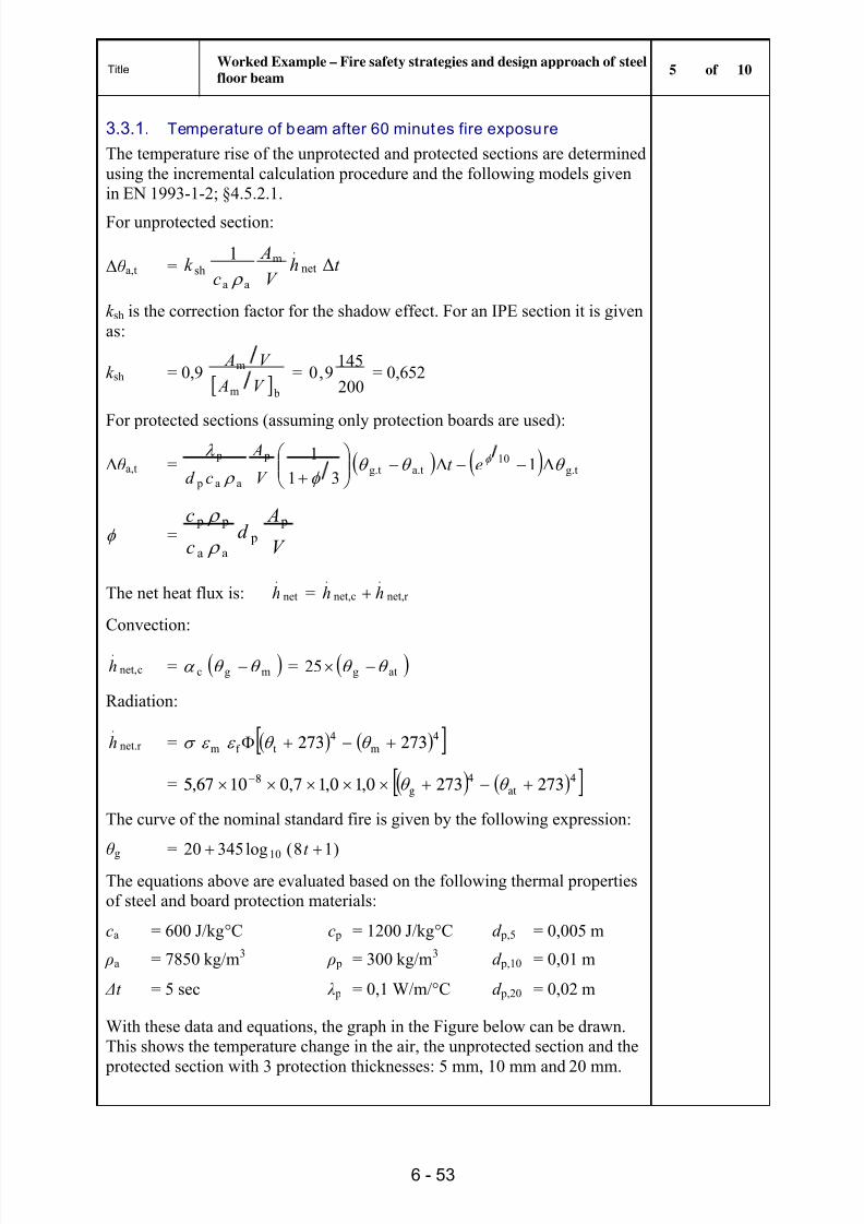
8/13/2019 MSB06 Fire Engineering 2010-03-25
http://slidepdf.com/reader/full/msb06-fire-engineering-2010-03-25 61/66
TitleWorked Example – Fire safety strategies and design approach of steelfloor beam 5 of 10
6 - 53
3.3.1. Temperature of beam after 60 minut es fire exposure
The temperature rise of the unprotected and protected sections are determinedusing the incremental calculation procedure and the following models givenin EN 1993-1-2; §4.5.2.1.
For unprotected section:
Δ θ a,t = t hV
Ac
k Δ1
net
.m
aash
k sh is the correction factor for the shadow effect. For an IPE section it is givenas:
k sh = 0,9 bm
m
V A
V A =
200
1459,0 = 0,652
For protected sections (assuming only protection boards are used):
Δ θ a,t = g.t10
a.tg.t p
aa p
pΔ1Δ
311
et
V
A
cd
=V
Ad
c
c p p
aa
p p
The net heat flux is: net
.h = r net,
.
net,c
.hh
Convection:
cnet,
.h = mgc = atg25
Radiation:
net.r
.h = 4
m4
t f m 273273
= 4at
4g
8 2732730,10,17,01067,5
The curve of the nominal standard fire is given by the following expression:
θ g = )18(log34520 10
t The equations above are evaluated based on the following thermal propertiesof steel and board protection materials:
ca = 600 J/kg C c p = 1200 J/kg C d p,5 = 0,005 m
ρa = 7850 kg/m 3 ρ p = 300 kg/m 3 d p,10 = 0,01 m
Δt = 5 sec λ p = 0,1 W/m/ C d p,20 = 0,02 m
With these data and equations, the graph in the Figure below can be drawn.This shows the temperature change in the air, the unprotected section and the
protected section with 3 protection thicknesses: 5 mm, 10 mm and 20 mm.
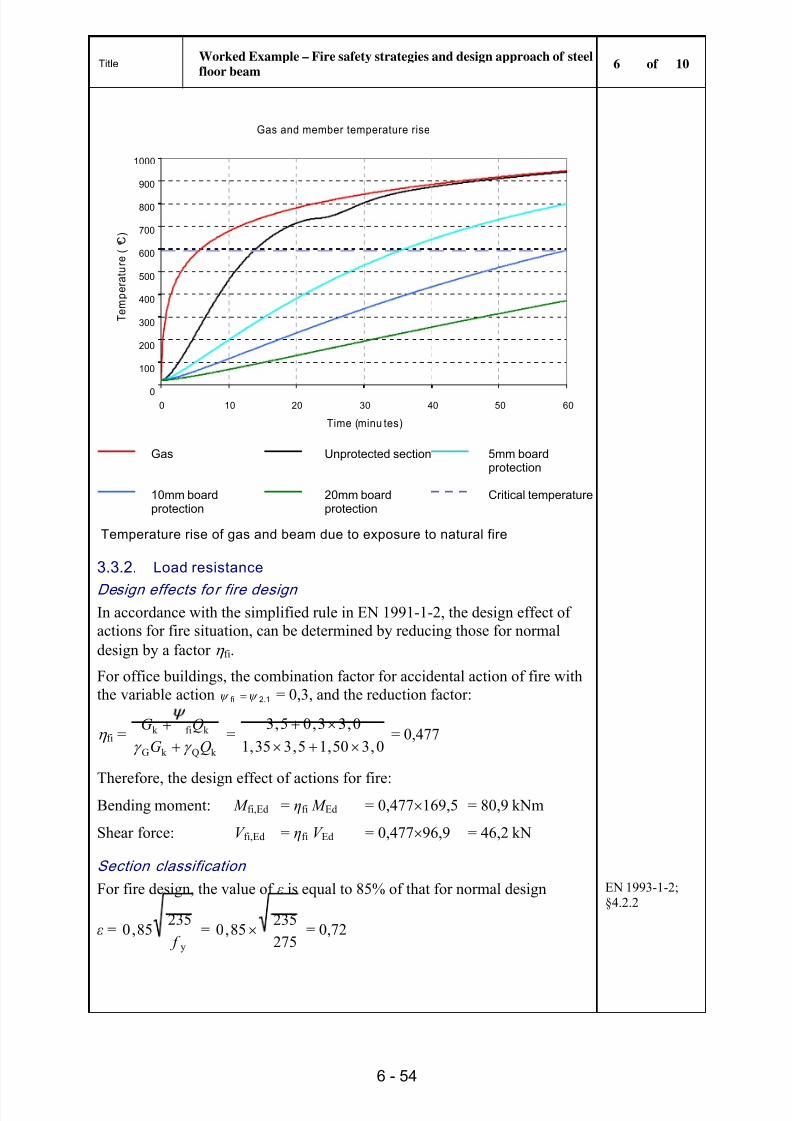
8/13/2019 MSB06 Fire Engineering 2010-03-25
http://slidepdf.com/reader/full/msb06-fire-engineering-2010-03-25 62/66
TitleWorked Example – Fire safety strategies and design approach of steelfloor beam 6 of 10
6 - 54
Gas and member temperature rise
0
100
200
300
400
500
600
700
800
900
1000
0 10 20 30 40 50 60
Time (minu tes)
T e m p e r a
t u r e
(
C )
Gas Unprotected section 5mm board
protection
10mm boardprotection
20mm boardprotection
Critical temperature
Temperature rise of gas and beam due to exposure to natural fire
3.3.2. Load resistance
Design effects fo r fire designIn accordance with the simplified rule in EN 1991-1-2, the design effect ofactions for fire situation, can be determined by reducing those for normaldesign by a factor fi.
For office buildings, the combination factor for accidental action of fire withthe variable action 1.2fi = 0,3, and the reduction factor:
fi =k Qk G
k fik
QGQG =
0,350,15,335,10,33,05,3
= 0,477
Therefore, the design effect of actions for fire:Bending moment: M fi,Ed = ηfi M Ed = 0,477 169,5 = 80,9 kNm
Shear force: V fi,Ed = ηfi V Ed = 0,477 96,9 = 46,2 kN
Section classification
For fire design, the value of ε is equal to 85% of that for normal design
ε =y
23585,0
f =
275235
85,0 = 0,72
EN 1993-1-2;§4.2.2

8/13/2019 MSB06 Fire Engineering 2010-03-25
http://slidepdf.com/reader/full/msb06-fire-engineering-2010-03-25 63/66
TitleWorked Example – Fire safety strategies and design approach of steelfloor beam 7 of 10
6 - 55
The ratios for local buckling of the section elements are:
Flange: cf /t f = 5,28 < [ cf /t f ]lim = 9 ε = 7,07
Web: cw/t w = 35,01 < [ cw/t w]lim = 72 ε = 56,57
The section is class 1.
Resistance of beam after 60 minutes fi re exposure
The moment resistance of a beam with non-uniform temperature along thedepth of its cross-section can be calculated as:
M fi,Rd = M fi,t,Rd = k y, θ W pl,y f y/(κ 1κ 2)
Where
k y, θ is the reduction factor for effective yield strength
κ 1, κ 2 are adaptation factors for non-uniform temperature across the
cross-section and along the beam
EN 1993-1-2;Table 3.1
EN 1993-1-2;§4.2.3.3
Unprotected beam
The temperature of the unprotected beam after 60 minutes fire exposure asobtained from the figure on Sheet 6, is:
θ at = 935 C
The reduction factor for effective yield strength can be obtained for:
θ a = 900 C k y, θ= 0,060
θ a = 1000 C k y, θ= 0,040
By interpolating for θ a = 935 C, we obtain:
k y, θ = 0,052
For an unprotected beam exposed on three sides, with a composite or concreteslab on side four:
κ 1 = 0,70
for any case where the supports of the beam are not statically indeterminate:
κ 2 = 0,85
Therefore the moment resistance of the beam is: M fi,Rd = 0,052 628 103 275/(0,7 1,0) 10 -6 = 12,83 kNm < = 80.9 kNm
Therefore the unprotected section is not safe. FAIL
10 mm board protection
Hence some protection is required for the beam. Following from the findingsof the previous simplified calculation based on the temperature, the firstoption to be explored is the 10mm fire board protection. This solution hasalready been found to be safe.
From the above Figure the temperature of this solution after 60 minutes of fire
exposure is:θ at = 594 C

8/13/2019 MSB06 Fire Engineering 2010-03-25
http://slidepdf.com/reader/full/msb06-fire-engineering-2010-03-25 64/66
TitleWorked Example – Fire safety strategies and design approach of steelfloor beam 8 of 10
6 - 56
The reduction factor for effective yield strength can be obtained for:
θ a = 500 C k y, θ= 0,780
θ a = 600 C k y, θ= 0,470
By interpolating for θ a = 594 C,
k y, θ = 0,46
The κ 1 and κ 2 factors are as previously obtained.
The moment resistance of the fully restrained beam with non-uniformtemperature along the depth of its cross-section:
M fi,Rd =21
yy pl,y,θ
f W k = 6
3
100,17,0
2751062846,0 = 113 kNm > 80,9
kNm
OK
The shear resistance can be obtained as follows:
V fi,Rd =M0
yvy, θ
3
f Ak =
0,13
275256746,0 = 187,5kN > 96,6 kN OK
The 3 side box protected section with 10 mm fire boards, is safe. OK
3.4. Make use of tensi le membrane actionFull size fire tests and real fire investigations have resulted in the conclusionthat the use of composite floors with steel decking leads to a much higher fire
resistance than predicted by the simple calculations adopted by the Eurocodeand shown in this example.
Section 8.
As long as the slab is well supported against its vertical deflection along lineswhich divide it into reasonably square areas, it is has been shown that tensilemembrane action can be developed as a load bearing mechanism,consequently providing a reserve load carrying resistance that simplifiedmodels do not account for.
As a result, it could be assumed that the beam in this example could be leftunprotected, while maintaining the level of safety required by EC3. Thisconstruction system has been shown to provide a higher fire resistance for
secondary beams but not for primary beams, and therefore care must be takenwhen adopting this solution.
3.5. FRACOFThe FRACOF software can be used to determine whether or not unprotectedsecondary steel beams are adequate when composite construction is used.

8/13/2019 MSB06 Fire Engineering 2010-03-25
http://slidepdf.com/reader/full/msb06-fire-engineering-2010-03-25 65/66
TitleWorked Example – Fire safety strategies and design approach of steelfloor beam 9 of 10
6 - 57
For illustration purposes, the IPE300 S275 beam used in this example is usedas a composite beam, with the following assumptions for use in Fracof:
IPE550 S275 primary beams
Cofrastra 40 deck 130 mm deep slab, using C25/30 concrete
ST 40 C mesh, 500 N/mm 2
All beams assumed to have 100% shear connection.
The design value of the actions for normal temperature is 9,23 kN/m 2. Thereduction factor for fire has been calculated as 0,477, which gives a fireaction of 4,4 kN/m 2.
For these input details, Fracof determines that it is adequate to use
unprotected IPE300 secondary beams for R60 fire resistance. The details aresummarised in the table below and graphically shown in the figure below.
According to the data shown in the table, after 20 minutes fire exposure, the beam capacity is 3,36 kN/m 2 < 4,4 kN/m 2 fire action.
Considering the slap capacity, the total resistance remains over 9 kN/m2
after60 minutes fire exposure, which means that the beam doesn not need to be protected.

8/13/2019 MSB06 Fire Engineering 2010-03-25
http://slidepdf.com/reader/full/msb06-fire-engineering-2010-03-25 66/66
TitleWorked Example – Fire safety strategies and design approach of steelfloor beam 10 of 10