MS5837-30BA - TME
16
TE CONNECTIVITY SENSORS /// MS5837-30BA26 REV C2 12/2019 Page 1 The MS5837-30BA is a high-resolution pressure and temperature sensor from TE Connectivity (TE) with I 2 C bus interface. This sensor is optimized for water depth measurement systems with a resolution of 0.2 cm. The sensor module includes a high linearity pressure sensor and an ultra-low power 24-bit ΔΣ ADC with internal factory calibrated coefficients. It provides a precise digital 24-bit pressure and temperature value and different operation modes that allow the user to optimize for conversion speed and current consumption. A high-resolution temperature output allows the implementation in depth measurement systems and thermometer function without any additional sensor. The MS5807-30BA can be interfaced to virtually any microcontroller. The communication protocol is simple, without the need of programming internal registers in the device. The gel protection and antimagnetic stainless-steel cap make the module water resistant. Small dimensions of only 3.3 x 3.3 x 2.75 mm allow integration in mobile devices. Enhanced construction and design materials allow for enhanced chemical endurance in applications with harsh liquid media environments with limited exposure. This sensor module generation is based on leading MEMS technology from TE proven experience and know-how in high volume manufacturing of sensors modules. FEATURES Ceramic and metal package: 3.3 x 3.3 x 2.75mm High resolution module: 0.2 cm (in water) Supply voltage: 1.5 to 3.6 V Low power: 0.6 µA (standby ≤ 0.1 µA at 25°C) Integrated digital pressure sensor (24-bit ΔΣ ADC) Operating range: 0 to 30 bar, -20 to +85 °C I 2 C interface No external components (internal oscillator) Water resistant sealing with 1.8 x 0.8mm O-ring High chemical endurance Shielded metal lid MS5837-30BA Ultra-small, gel-filled, pressure sensor with stainless steel cap APPLICATIONS Dive Computers Mobile Water Depth Measurement Systems Fitness Trackers Wearables
Transcript of MS5837-30BA - TME
TE CONNECTIVITY SENSORS /// MS5837-30BA26 REV C2 12/2019
Page 1
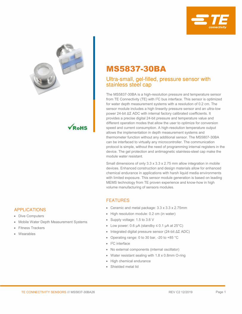
The MS5837-30BA is a high-resolution pressure and temperature sensor from TE Connectivity (TE) with I2C bus interface. This sensor is optimized for water depth measurement systems with a resolution of 0.2 cm. The sensor module includes a high linearity pressure sensor and an ultra-low power 24-bit ΔΣ ADC with internal factory calibrated coefficients. It provides a precise digital 24-bit pressure and temperature value and different operation modes that allow the user to optimize for conversion speed and current consumption. A high-resolution temperature output allows the implementation in depth measurement systems and thermometer function without any additional sensor. The MS5807-30BA can be interfaced to virtually any microcontroller. The communication protocol is simple, without the need of programming internal registers in the device. The gel protection and antimagnetic stainless-steel cap make the module water resistant.
Small dimensions of only 3.3 x 3.3 x 2.75 mm allow integration in mobile devices. Enhanced construction and design materials allow for enhanced
chemical endurance in applications with harsh liquid media environments
with limited exposure. This sensor module generation is based on leading MEMS technology from TE proven experience and know-how in high volume manufacturing of sensors modules.
FEATURES
Ceramic and metal package: 3.3 x 3.3 x 2.75mm
High resolution module: 0.2 cm (in water) Supply voltage: 1.5 to 3.6 V
Low power: 0.6 µA (standby ≤ 0.1 µA at 25°C) Integrated digital pressure sensor (24-bit ΔΣ ADC) Operating range: 0 to 30 bar, -20 to +85 °C
I2C interface
No external components (internal oscillator) Water resistant sealing with 1.8 x 0.8mm O-ring
High chemical endurance
Shielded metal lid
MS5837-30BA
Ultra-small, gel-filled, pressure sensor with stainless steel cap
APPLICATIONS
Dive Computers
Mobile Water Depth Measurement Systems
Fitness Trackers
Wearables

MS5837-30BA
Ultra-small, gel-filled pressure sensor with stainless steel cap
TE CONNECTIVITY SENSORS /// MS5837-30BA REV C2 12/2019
Page 2
PERFORMANCE SPECIFICATIONS
ABSOLUTE MAXIMUM RATINGS
Parameter Symbol Conditions Min. Typ. Max Unit
Supply voltage VDD -0.3 +4 V
Storage temperature TS -40 +85 °C
Overpressure Pmax ISO 6425 (1) 50 bar
Maximum Soldering Temperature (2)
Tmax 40 sec max 250 °C
ESD rating Human Body Model
-2 +2 kV
Latch up JEDEC standard No 78
-100 +100 mA
(1): Pressure ramp up/down min 60s (2): Refer to application note 808
ELECTRICAL CHARACTERISTICS
Parameter Symbol Conditions Min. Typ. Max Unit
Operating Supply voltage VDD 1.5 3.0 3.6 V
Operating Temperature T -20 +25 +85 °C
Supply current
(1 sample per sec.) IDD
OSR 8192
4096
2048
1024
512
256
20.09
10.05
5.02
2.51
1.26
0.63
µA
Peak supply current during conversion 1.25 mA
Standby supply current at 25°C (VDD = 3.0V) 0.01 0.1 µA
Power supply hold off for internal reset (3) VDD < 0.1V 200 ms
VDD Capacitor From VDD to GND 100 470 nF (3): Supply voltage power up must be continuous from GND to VDD without any step
ANALOG DIGITAL CONVERTER (ADC)
Parameter Symbol Conditions Min. Typ. Max Unit
Output Word 24 bit
Conversion time (4) tc
OSR 8192
4096
2048
1024
512
256
14.80
7.40
3.72
1.88
0.95
0.48
16.44
8.22
4.13
2.08
1.06
0.54
18.08
9.04
4.54
2.28
1.17
0.60
ms
(4): Maximum values must be used to determine waiting times in I2C communication

MS5837-30BA
Ultra-small, gel-filled pressure sensor with stainless steel cap
TE CONNECTIVITY SENSORS /// MS5837-30BA REV C2 12/2019
Page 3
PERFORMANCE SPECIFICATIONS (CONTINUED)
PRESSURE OUTPUT CHARACTERISTICS (VDD = 3 V, T = 25°C UNLESS OTHERWISE NOTED)
Parameter Conditions Min. Typ. Max Unit
Operating Pressure Range Prange 0 30 bar
Absolute Accuracy (1)(4),
Temperature range: 0 … 45°C
Version -01 0 … 6 bar
-50 +50 mbar
Version -26 -75 +75 mbar
Absolute Accuracy (1)(4),
Temperature range: 0 … 45°C
0 … 20 bar 0 … 30 bar
-100
-200
+100
+200 mbar
Absolute Accuracy (1)(4),
Temperature range: -20 … 85°C
Version -01 0 … 6 bar
-100 +100 mbar
Version -26 -150 +150 mbar
Absolute Accuracy (1)(4),
Temperature range: -20 … 85°C
0 … 20 bar 0 … 30 bar
-200
-400
+200
+400 mbar
Maximum error with supply voltage (2)
Version -01 VDD = 1.5 V … 3.6 V
±30 mbar
Version -26 ±75 mbar
Long-term stability ±30 mbar/yr
Reflow soldering impact
IPC/JEDEC J-STD-020C
Version -01 ±8 mbar
Version -26 ±30 mbar
Recovering time after reflow (3) 7 days
Resolution RMS
OSR 8192
4096
2048
1024
512
256
0.20
0.28
0.38
0.54
0.84
1.57
mbar
(1) With autozero at one pressure point
(2) With autozero at 3V point
(3) Time to recover at least 66% of the reflow impact.
(4) Wet/dry cycle: sensor must be dried typically once a day
TEMPERATURE OUTPUT CHARACTERISTICS (VDD = 3 V, T = 25°C UNLESS OTHERWISE NOTED)
Parameter Conditions Min. Typ. Max Unit
Absolute Accuracy -20°C … +85°C -4 +4 °C
Maximum error with supply voltage
VDD = 1.5 V … 3.6 V ± 0.6 °C
Resolution RMS
OSR 8192
4096
2048
1024
512
256
0.0022
0.0026
0.0033
0.0041
0.0055
0.0086
°C

MS5837-30BA
Ultra-small, gel-filled pressure sensor with stainless steel cap
TE CONNECTIVITY SENSORS /// MS5837-30BA REV C2 12/2019
Page 4
PERFORMANCE SPECIFICATIONS (CONTINUED)
DIGITAL INPUTS (SCL, SDA)
Parameter Symbol Conditions Min. Typ. Max Unit
Serial data clock SCL 400 kHz
Input high voltage VIH 80% VDD 100% VDD V
Input low voltage VIL 0% VDD 20% VDD V
Input leakage current Ileak25°C at 25°c 0.1 µA
DIGITAL OUTPUTS (SDA)
Parameter Symbol Conditions Min. Typ. Max Unit
Output high voltage VOH Isource = 0.6 mA 80% VDD 100% VDD V
Output low voltage VOL Isink = 0.6 mA 0% VDD 20% VDD V

MS5837-30BA
Ultra-small, gel-filled pressure sensor with stainless steel cap
TE CONNECTIVITY SENSORS /// MS5837-30BA REV C2 12/2019
Page 5
TYPICAL PERFORMANCE CHARACTERISTICS
PRESSURE ERROR VS PRESSURE AND TEMPERATURE
TEMPERATURE ERROR VS PRESSURE AND TEMPERATURE
PRESSURE AND TEMPERATURE VS SUPPLY VOLTAGE
-150
-100
-50
0
50
100
150
0 5000 10000 15000 20000 25000 30000
Pre
ssu
re e
rro
r [m
ba
r]
Pressure [mbar]
Absolute Pressure error vs pressure (typical):
45°C
25°C
0°C
-400
-300
-200
-100
0
100
200
300
400
-20 0 20 40 60
Pre
ssu
re e
rro
r [m
ba
r]
Temperature [°C]
1 bar
6 bar
20 bar
30 bar
-5.0
-4.0
-3.0
-2.0
-1.0
0.0
1.0
2.0
3.0
4.0
5.0
0 5000 10000 15000 20000 25000 30000
Te
mp
era
ture
err
or
[°C
]
Pressure [mbar]
Temperature Error vs Pressure (typical):
45°C
25°C
0°C
-5.0
-4.0
-3.0
-2.0
-1.0
0.0
1.0
2.0
3.0
4.0
5.0
-20 0 20 40 60 80
Te
mp
era
ture
err
or
[°C
]
Temperature [°C]
Temperature Error vs Temperature (typical):
1 Bar
6 bar
20 bar
30 bar
-75.0
-50.0
-25.0
0.0
25.0
50.0
75.0
1.5 2.0 2.5 3.0 3.5
Pre
ssu
re E
rro
r 2
nd
[m
bar
]
Power supply [V]
Pressure error vs Supply voltage (typical)
1b, 25°C
-2.0
-1.5
-1.0
-0.5
0.0
0.5
1.0
1.5
2.0
1.50 2.00 2.50 3.00 3.50
Tem
pera
ture
Err
or 2
nd [
°C]
Power supply [V]
Temperature error vs Supply voltage (typical)
1bar, 25°C

MS5837-30BA
Ultra-small, gel-filled pressure sensor with stainless steel cap
TE CONNECTIVITY SENSORS /// MS5837-30BA REV C2 12/2019
Page 6
FUNCTIONAL DESCRIPTION
GENERAL
The MS5837-30BA consists of a piezo-resistive sensor and a sensor interface IC. The main function of the MS5837-
30BA is to convert the uncompensated analog output voltage from the piezo-resistive pressure sensor to a 24-bit
digital value, as well as providing a 24-bit digital value for the temperature of the sensor
FACTORY CALIBRATION
Every module is individually factory calibrated at two temperatures and two pressures. As a result, 6 coefficients
necessary to compensate for process variations and temperature variations are calculated and stored in the 112-
bit PROM of each module. These bits (partitioned into 6 coefficients W1 to W6) must be read by the microcontroller
software and used in the program converting D1 and D2 into compensated pressure and temperature values.
The coefficients W0 is for factory configuration and CRC.
SERIAL I2C INTERFACE
The external microcontroller clocks in the data through the input SCL (Serial CLock) and SDA (Serial DAta). The
sensor responds on the same pin SDA which is bidirectional for the I2C bus interface. So this interface type uses
only 2 signal lines and does not require a chip select.
Module ref Mode Pins used Address (7 bits)
MS5837-30BA I2C SDA, SCL 0x76 (1110110 b)

MS5837-30BA
Ultra-small, gel-filled pressure sensor with stainless steel cap
TE CONNECTIVITY SENSORS /// MS5837-30BA REV C2 12/2019
Page 7
COMMANDS
The MS5837-30BA has only five basic commands:
1. Reset
2. Read PROM (128 bit of calibration words)
3. D1 conversion
4. D2 conversion
5. Read ADC result (24 bit pressure / temperature)
Size of each command is 1 byte (8 bits) as described in the table below. After ADC read commands the device will
return 24 bit result and after the PROM read 16bit result. The address of the PROM is embedded inside of the
PROM read command using the a2, a1 and a0 bits.
Command byte hex value
Bit number 0 1 2 3 4 5 6 7
Bit name PRM
COV - Typ Ad2/Os2
Ad1/Os1
Ad0/Os0
Stop
Command
Reset 0 0 0 1 1 1 1 0 0x1E
Convert D1 (OSR=256) 0 1 0 0 0 0 0 0 0x40
Convert D1 (OSR=512) 0 1 0 0 0 0 1 0 0x42
Convert D1 (OSR=1024) 0 1 0 0 0 1 0 0 0x44
Convert D1 (OSR=2048) 0 1 0 0 0 1 1 0 0x46
Convert D1 (OSR=4096) 0 1 0 0 1 0 0 0 0x48
Convert D2 (OSR=256) 0 1 0 1 0 0 0 0 0x50
Convert D2 (OSR=512) 0 1 0 1 0 0 1 0 0x52
Convert D2 (OSR=1024) 0 1 0 1 0 1 0 0 0x54
Convert D2 (OSR=2048) 0 1 0 1 0 1 1 0 0x56
Convert D2 (OSR=4096) 0 1 0 1 1 0 0 0 0x58
ADC Read 0 0 0 0 0 0 0 0 0x00
PROM Read 1 0 1 0 Ad2 Ad1 Ad0 0 0xA0 to
0xAC
Figure 1: Command Structure

MS5837-30BA
Ultra-small, gel-filled pressure sensor with stainless steel cap
TE CONNECTIVITY SENSORS /// MS5837-30BA REV C2 12/2019
Page 8
I2C INTERFACE
RESET SEQUENCE
The Reset sequence shall be sent once after power-on to make sure that the calibration PROM gets loaded into
the internal register. It can be also used to reset the device PROM from an unknown condition.
The reset can be sent at any time. In the event that there is not a successful power on reset this may be caused by
the SDA being blocked by the module in the acknowledge state. The only way to get the MS5837-30BA to function
is to send several SCLs followed by a reset sequence or to repeat power on reset.
Figure 2: I2C Reset Command
PROM READ SEQUENCE
The read command for PROM shall be executed once after reset by the user to read the content of the calibration
PROM and to calculate the calibration coefficients. There are in total 7 addresses resulting in a total memory of 112
bit. Addresses contain factory data and the setup, calibration coefficients, the serial code and CRC. The command
sequence is 8 bits long with a 16 bit result which is clocked with the MSB first. The PROM Read command consists
of two parts. First command sets up the system into PROM read mode. The second part gets the data from the
system.
Figure 3: I2C Command to read memory address= 011
Figure 4: I2C answer from MS5837-30BA
1 1 1 0 1 1 0 0 0 0 0 0 1 1 1 1 0 0
S W A A P
From Master S = Start Condition W = Write A = Acknowledge
From Slave P = Stop Condition R = Read N = Not Acknowledge
cmd byte
Device Address
Device Address
command
1 1 1 0 1 1 0 0 0 1 0 1 0 0 1 1 0 0
S W A A P
From Master S = Start Condition W = Write A = Acknowledge
From Slave P = Stop Condition R = Read N = Not Acknowledge
Device Address
Device Address cmd byte
command
1 1 1 0 1 1 0 1 0 X X X X X X X X 0 X X X X X X X X 0
S R A A N P
From Master S = Start Condition W = Write A = Acknowledge
From Slave P = Stop Condition R = Read N = Not Acknowledage
Memory bit 7 - 0
Device Address
Device Address Memory bit 15 - 8
data data

MS5837-30BA
Ultra-small, gel-filled pressure sensor with stainless steel cap
TE CONNECTIVITY SENSORS /// MS5837-30BA REV C2 12/2019
Page 9
CONVERSION SEQUENCE
The conversion command is used to initiate uncompensated pressure (D1) or uncompensated temperature (D2)
conversion. After the conversion, using ADC read command the result is clocked out with the MSB first. If the
conversion is not executed before the ADC read command, or the ADC read command is repeated, it will give 0 as
the output result. If the ADC read command is sent during conversion the result will be 0, the conversion will not
stop and the final result will be wrong. Conversion sequence sent during the already started conversion process will
yield incorrect result as well. A conversion can be started by sending the command to MS5837-30BA. When
command is sent to the system it stays busy until conversion is done. When conversion is finished the data can be
accessed by sending a Read command, when acknowledge is sent from the MS5837-30BA, 24 SCL cycles may
be sent to receive all result bits. Every 8 bits the system waits for an acknowledge signal.
Figure 5: I2C command to initiate a pressure conversion (OSR=4096, typ=D1)
Figure 6: I2C ADC read sequence
Figure 7: I2C answer from MS5837-30BA
Version PROM Word 0 programming
For product type, the bits [11:5] of memory address 0 must be programmed with the following fixed values:
MS5837-30BA26
Address 15 14 13 12 11 10 9 8 7 6 5 4 3 2 1 0
0 crc 0 0 1 1 0 1 0 factory settings
1 1 1 0 1 1 0 0 0 0 1 0 0 1 0 0 0 0
S W A A P
From Master S = Start Condition W = Write A = Acknowledge
From Slave P = Stop Condition R = Read N = Not Acknowledge
cmd byte
Device Address
Device Address
command
1 1 1 0 1 1 0 0 0 0 0 0 0 0 0 0 0 0
S W A A P
From Master S = Start Condition W = Write A = Acknowledge
From Slave P = Stop Condition R = Read N = Not Acknowledge
Device Address
Device Address cmd byte
command
1 1 1 0 1 1 0 1 0 X X X X X X X X 0 X X X X X X X X 0 X X X X X X X X 0
S R A A A N P
From Master S = Start Condition W = Write A = Acknowledge From Slave P = Stop Condition R = Read N = Not Acknowledge
Data 7 - 0 Data 15 - 8 Device Address Device Address data data
Data 23-16 data
MS5837-30BA
Ultra-small, gel-filled pressure sensor with stainless steel cap
TE CONNECTIVITY SENSORS /// MS5837-30BA REV C2 12/2019
Page 10
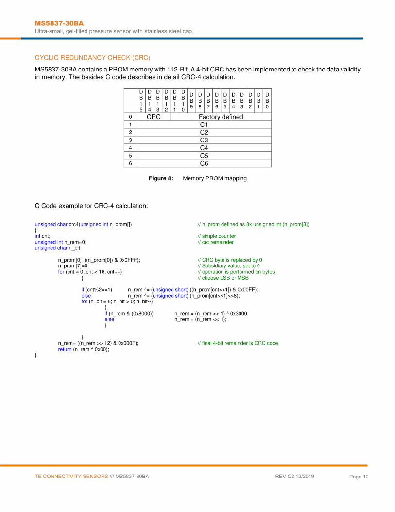
CYCLIC REDUNDANCY CHECK (CRC)
MS5837-30BA contains a PROM memory with 112-Bit. A 4-bit CRC has been implemented to check the data validity
in memory. The besides C code describes in detail CRC-4 calculation.
DB15
DB14
DB13
DB12
DB11
DB10
DB9
DB8
DB7
DB6
DB5
DB4
DB3
DB2
DB1
DB0
0 CRC Factory defined 1 C1 2 C2 3 C3 4 C4 5 C5 6 C6
Figure 8: Memory PROM mapping
C Code example for CRC-4 calculation:
unsigned char crc4(unsigned int n_prom[]) // n_prom defined as 8x unsigned int (n_prom[8]) { int cnt; // simple counter unsigned int n_rem=0; // crc remainder unsigned char n_bit;
n_prom[0]=((n_prom[0]) & 0x0FFF); // CRC byte is replaced by 0 n_prom[7]=0; // Subsidiary value, set to 0 for (cnt = 0; cnt < 16; cnt++) // operation is performed on bytes { // choose LSB or MSB if (cnt%2==1) n_rem ^= (unsigned short) ((n_prom[cnt>>1]) & 0x00FF); else n_rem ^= (unsigned short) (n_prom[cnt>>1]>>8); for (n_bit = 8; n_bit > 0; n_bit--) { if (n_rem & (0x8000)) n_rem = (n_rem << 1) ^ 0x3000; else n_rem = (n_rem << 1); } } n_rem= ((n_rem >> 12) & 0x000F); // final 4-bit remainder is CRC code return (n_rem ^ 0x00); }

MS5837-30BA
Ultra-small, gel-filled pressure sensor with stainless steel cap
TE CONNECTIVITY SENSORS /// MS5837-30BA REV C2 12/2019
Page 11
PRESSURE AND TEMPERATURE CALCULATION
Figure 9: Flow chart for pressure and temperature reading and software compensation.
Size [1]
[bit] min max
C1 Pressure sensitivity | SENS T1 unsigned int 16 16 0 65535 34982
C2 Pressure offset | OFF T1 unsigned int 16 16 0 65535 36352
C3 Temperature coefficient of pressure sensitivity | TCS unsigned int 16 16 0 65535 20328
C4 Temperature coefficient of pressure offset | TCO unsigned int 16 16 0 65535 22354
C5 Reference temperature | T REF unsigned int 16 16 0 65535 26646
C6 Temperature coefficient of the temperature | TEMPSENS unsigned int 16 16 0 65535 26146
D1 Digital pressure value unsigned int 32 24 0 16777215 4958179
D2 Digital temperature value unsigned int 32 24 0 16777215 6815414
dT Difference between actual and reference temperature dT = D2 - T REF = D2 - C5 * 2
8 signed int 32 25 -16776960 16777215 -5962
1981
= 19.81 °C
OFF Offset at actual temperature OFF
= OFF T1
+ TCO
* dT = C2
* 2 16
+ (C4
* dT ) / 2
7 signed int 64 41 -17179344900 25769410560 2381326464
SENS Sensitivity at actual temperature SENS
= SENS T1
+ TCS
* dT =
C1 * 2 15
+ ( C3
* dT ) / 2
8 signed int 64 41 -8589672450 12884705280 1145816755
39998
= 3999.8 mbar
Notes [1] Maximal size of intermediate result during evaluation of variable
300000 0 58
P
Recommended variable type
Description | Equation
signed int 32 Actual temperature (-40…85°C with 0.01°C resolution) TEMP = 20°C+dT*TEMPSENS = 2000+dT *C6 /2
23
Read digital pressure and temperature data
signed int 32 Temperature compensated pressure (0…30 bar with 0.25mbar resolution) P = D1 * SENS - OFF = (D1 * SENS / 2
21 - OFF) / 2 13
Convert calibration data into coefficients (see bit pattern of W1 to W4)
Variable Example /
Typical Value
Calculate temperature compensated pressure
8500 -4000 TEMP 41
Start Maximum values for calculation results:
P MIN = 0 bar P MAX = 30 bar T MIN = -20°C T MAX = 85°C T REF = 20°C
Read calibration data (factory calibrated) from PROM
Read digital pressure and temperature data
Calculate temperature
Calculate temperature compensated pressure
Display pressure and temperature value

MS5837-30BA
Ultra-small, gel-filled pressure sensor with stainless steel cap
TE CONNECTIVITY SENSORS /// MS5837-30BA REV C2 12/2019
Page 12
SECOND ORDER TEMPERATURE COMPENSATION
Yes No
SENSi = 5 (TEMP – 2000)2 / 2
3
SENS2 = SENS - SENSi
(TEMP/ 100)< 20°C
Low temperature
OFFi = 1 (TEMP – 2000)2 / 2
4
OFFi = 3 (TEMP – 2000)2 / 2
1
OFF2 = OFF - OFFi
TEMP2 = (TEMP – Ti) / 100 [°C]
Low temperature
High temperature
Calculate pressure and temperature 2nd
order
(TEMP/ 100) < -15°C
No Yes
OFFi = OFFi + 7 (TEMP + 1500)2
Very low temperature
SENSi = 0
Ti = 3 dT2 / 2
33 Ti = 2 dT2 / 2
37
SENSi = SENSi + 4 (TEMP + 1500)2
Pressure and Temperature parameters values first order: OFF, SENS and TEMP
P2 = ((( D1 SENS2 ) / 221
– OFF2) / 213
) / 10 [mbar]
Figure 10: Flow chart for pressure and temperature to the optimum accuracy.

MS5837-30BA
Ultra-small, gel-filled pressure sensor with stainless steel cap
TE CONNECTIVITY SENSORS /// MS5837-30BA REV C2 12/2019
Page 13
APPLICATION CIRCUIT
The MS5837 is a circuit that can be used in conjunction with a microcontroller in mobile altimeter applications.
Figure 11: Typical application circuit
PIN CONFIGURATION AND DEVICE PACKAGE OUTLINE
UNLESS OTHERWISE SPECIFIED DIMENSIONS ARE IN MILLIMETERS. GENERAL TOLERANCE ± 0.1
1 GND GROUND
2 VDD POSITIVE SUPPLY
3 SCL I2C CLOCK
4 SDA I2C DATA
Figure 12: Package outlines and Pin configuration

MS5837-30BA
Ultra-small, gel-filled pressure sensor with stainless steel cap
TE CONNECTIVITY SENSORS /// MS5837-30BA REV C2 12/2019
Page 14
RECOMMENDED PAD LAYOUT
Pad layout for bottom side of the MS5837-30BA soldered onto printed circuit board.
Figure 13: Pad layout
SHIPPING PACKAGE

MS5837-30BA
Ultra-small, gel-filled pressure sensor with stainless steel cap
TE CONNECTIVITY SENSORS /// MS5837-30BA REV C2 12/2019
Page 15
MOUNTING AND ASSEMBLY CONSIDERATIONS
SOLDERING
Please refer to the application note AN808 available on our website for all soldering recommendations.
MOUNTING
The MS5837-30BA can be placed with automatic Pick & Place equipment using vacuum nozzles. It will not be
damaged by the vacuum. Due to the low stress assembly the sensor does not show pressure hysteresis effects. It
is important to solder all contact pads.
CONNECTION TO PCB
The package outline of the module allows the use of a flexible PCB for interconnection. This can be important for
applications in watches and other special devices.
SEALING WITH O-RINGS
In applications such as outdoor watches the electronics must be protected against direct water or humidity. For
such applications the MS5837-30BA provides the possibility to seal with an O-ring. The O-ring shall be placed at
the groove location, i.e. the small outer diameter of the metal lid. The following O-ring / housing dimensions are
recommended:
O-ring inner diameter 1.8 ± 0.05 mm
O-ring cross-section diameter 0.8 ± 0.03 mm
Housing bore diameter 3.07 ± 0.03 mm
Please refer to the application note available on our website for O-ring mounting recommendations.
CLEANING
The MS5837-30BA has been manufactured under clean-room conditions. It is therefore recommended to assemble
the sensor under class 10’000 or better conditions. Should this not be possible, it is recommended to protect the sensor opening during assembly from entering particles and dust. To avoid cleaning of the PCB, solder paste of
type “no-clean” shall be used. Warning: cleaning might damage the sensor.
ESD PRECAUTIONS
The electrical contact pads are protected against ESD. It is therefore essential to ground machines and personnel
properly during assembly and handling of the device. The MS5837-30BA is shipped in antistatic transport boxes.
Any test adapters or production transport boxes used during the assembly of the sensor shall be of an equivalent
antistatic material.
DECOUPLING CAPACITOR
Particular care must be taken when connecting the device to the power supply. A minimum of 100nF ceramic
capacitor must be placed as close as possible to the MS5837-30BA VDD pin. This capacitor will stabilize the power
supply during data conversion and thus, provide the highest possible accuracy.

MS5837-30BA
Ultra-small, gel-filled pressure sensor with stainless steel cap
TE CONNECTIVITY SENSORS /// MS5837-30BA REV C2 12/2019
Page 16
ORDERING INFORMATION
PART NUMBER DESCRIPTION SHIELDING HIGH ENDURANCE
20001149-00 MS5837-30BA26 30BA HE LS T&R PRESS SEN X X
te.com/sensorsolutions
Measurement Specialties (MEAS), TE Connectivity, TE Connectivity (logo) and EVERY CONNECTION COUNTS are trademarks. All other logos, products and/or company names referred to herein might be trademarks of their respective owners.
The information given herein, including drawings, illustrations and schematics which are intended for illustration purposes only, is believed to be reliable. However, TE Connectivity makes no warranties as to its accuracy or completeness and disclaims any liability in connection with its use. TE Connectivity‘s obligations shall only be as set forth in TE Connectivity‘s Standard Terms and Conditions of Sale for this product and in no case will TE Connectivity be liable for any incidental, indirect or consequential damages arising out of the sale, resale, use or misuse of the product. Users of TE Connectivity products should make their own evaluation to determine the suitability of each such product for the specific application.
© 2019 TE Connectivity Ltd. family of companies All Rights Reserved.
NORTH AMERICA Tel +1 800 522 6752 [email protected]
EUROPE Tel +31 73 624 6999 [email protected]
ASIA Tel +86 0400 820 6015 [email protected]


![TME-DC [ ] - Sew Many Parts, Inc. of Contents z TME-DC GENERAL VIEW z TME-DC FRAME … CD-1 z TME-DC TABLE … CD-2-1 z TME-DC AUTO SUB TABLE …](https://static.fdocuments.us/doc/165x107/5b1d28797f8b9add7f8b64eb/tme-dc-sew-many-parts-inc-of-contents-z-tme-dc-general-view-z-tme-dc-frame.jpg)