MS2500E Transmitter Operator's Manual - Alabama Specialty
21
MS2500E Transmitter Operator’s Manual Metal Samples Company A Division of Alabama Specialty Products, Inc. 152 Metal Samples Rd., Munford, AL 36268 Phone: (256) 358-4202 Fax: (256) 358-4515 E-mail: [email protected] Internet: www.metalsamples.com
Transcript of MS2500E Transmitter Operator's Manual - Alabama Specialty

MS2500E TransmitterOperator’s Manual
Metal Samples CompanyA Division of Alabama Specialty Products, Inc.
152 Metal Samples Rd., Munford, AL 36268 Phone: (256) 358-4202 Fax: (256) 358-4515 E-mail: [email protected] Internet: www.metalsamples.com

.

Table of Contents
I. General Description ........................................................................................................ 1A. Introduction .............................................................................................................. 1B. General Description .................................................................................................. 1C. Principles of Operation ............................................................................................. 2D. Technical Specifications ........................................................................................... 3
II. Installation and Operation .................................................................................................. 4A. Receiving the MS2500E Transmitter ........................................................................... 4B. Installation .................................................................................................................. 4
1. Mechanical Mounting ............................................................................................ 4 Figure 1. Preferred Installation ........................................................................... 5
2. Electrical Connection .............................................................................................. 5C. Safe Area Wiring ........................................................................................................ 6D. Hazardous Area Wiring ............................................................................................... 6
1. Probe Selection Terminals ..................................................................................... 72. Calibration ............................................................................................................ 7
Figure 2. Calibration Connections ...................................................................... 8 Figure 3. Switch Locations ................................................................................ 9
3. Operation ............................................................................................................. 9 Figure 4. Output Linear Relationship .................................................................. 10
4. Determining Corrosion Rate .................................................................................. 10E. Selecting the Probe ..................................................................................................... 10
1. Probe Replacement Calculation ............................................................................. 10F. Maintenance ............................................................................................................... 11G. Returning the Instrument for Repair ............................................................................. 12
III. Maintenance and Repair Instructions.................................................................................. 13
IV. Warranty Information ........................................................................................................ 15

.

1
I. General Description
A. Introduction
The development of the MS2500E Transmitter provides the corrosion engineer with a simple,lowcost, computer-compatible corrosion monitoring instrument. Designed to be incorporated intoa 20 mA current loop, the MS2500E Transmitter uses the principle of electrical resistance to deter-mine the corrosion rate of a metal specimen immersed in a process stream. The electrical resis-tance of a metal specimen is a physical property dependent on the specimen’s physical dimensions(length and cross section) and on the metal’s inherent resistivity. If all other factors remain con-stant, any decrease in the cross section of a metal specimen will increase its resistance.
The MS2500E Transmitter is used in process systems for which appropriately designed electricalresistance probes are available. Such systems include, but are not limited to nonaqueous, noncon-ductive process streams, process streams where erosion-corrosion occurs and process streamshaving either a predominant liquid or vapor phase. Examples of industries where such processstreams are found include chemical plants, refineries, gas plants, oil and gas production systems,paper mills, power plants and tank farms.
B. General Description
The MS2500E Transmitter provides a two-wire interface between a single electrical resistanceprobe and a customer-supplied process computer, recorder, or control system, or between a probeand the MS2510 Receiver (ordered separately). The MS2510 Receiver and the MS2500E Trans-mitter function together as a stand-alone, single-station monitoring system.
The current loop connecting the Transmitter and the data receiving station may be up to 11 miles inlength for circuits that do not include safety barriers and up to 1 mile for intrinsically safe circuits(circuits that do include safety barriers or their equivalent). A customer-supplied DC power sourceenergizes the monitoring system. Probe signals representing metal loss are processed by the Trans-mitter and are relayed to the data receiving station as a 4-20mA signal.
Unlike similar devices available from other manufacturers, the MS2500E Transmitter does notrequire factory modification to accommodate different probe types. A simple field calibration pro-cedure permits the MS2500E to be used with any electrical resistance probe. The MS2500E willaccommodate all Metal Samples electrical resistance probes and most of the electrical resistance probesof other manufacturers.
The MS2500E Transmitter is available in one enclosure style. This style is mounted on any flatsurface up to 5 feet from the probe and is connected to the probe via a special cable, modelCb-8140 (included).

2
C. Principles of Operation
Electrical resistance probes contain a continuous sensing device that is divided into “elements”connected in series. These elements include a measuring element and a reference element. Themeasuring element is exposed to the corroding environment. The resulting loss of metal de-creases the measuring element’s thickness and causes an increase in this element’s resistance.The reference element is protected from the corroding environment and retains its originalthickness and resistance. The MS2500E Transmitter is powered by a customer-supplied 10-35VDC power source. As the probe’s measuring element corrodes, the Transmitter sends to the datareceiving station a proportional 4-20mA signal that represents the element’s metal loss.
The measurement technique employed by the Transmitter eliminates electrical resistancechanges due to temperature fluctuations by measuring the ratio of the exposed measuringelement’s resistance to that of the protected reference element’s resistance exposed. This ratiothen regulates Transmitter output current (4-20mA) such that it represents the metal lost by theexposed element. For example, a Transmitter output current of 4mA indicates 0 (zero) corro-sion. An output current measurement of 20mA indicates the end of probe life.
The Transmitter’s 4-20 mA current range is “divided” into 1,000 probe reading units. A singleunit represents 0.001 of probe life. Probe life is equivalent to the amount of metal that themeasuring element can lose during the useful life of the probe. Initial probe measurementstaken when the probe is first installed will be at approximately 0 to 100 units. The maximumprobe measurement (20 mA) is equivalent to 1000 units.
Expected probe life for elements presently available from Metal Samples are listed in the table below.
epyTtnemelE ssenkcihT)sllim(
efiLevitceffE)sllim(
pooLralubuT 4 2
8 4
pooLeriW 04 01
08 02
lacirdnilyC 01 5
02 01
csiDhsulF 5 5.2
01 5

3
D. Technical Specifications
ModelMS2500E - Loop-Powered ER Transmitter (Ordering # IN2500)
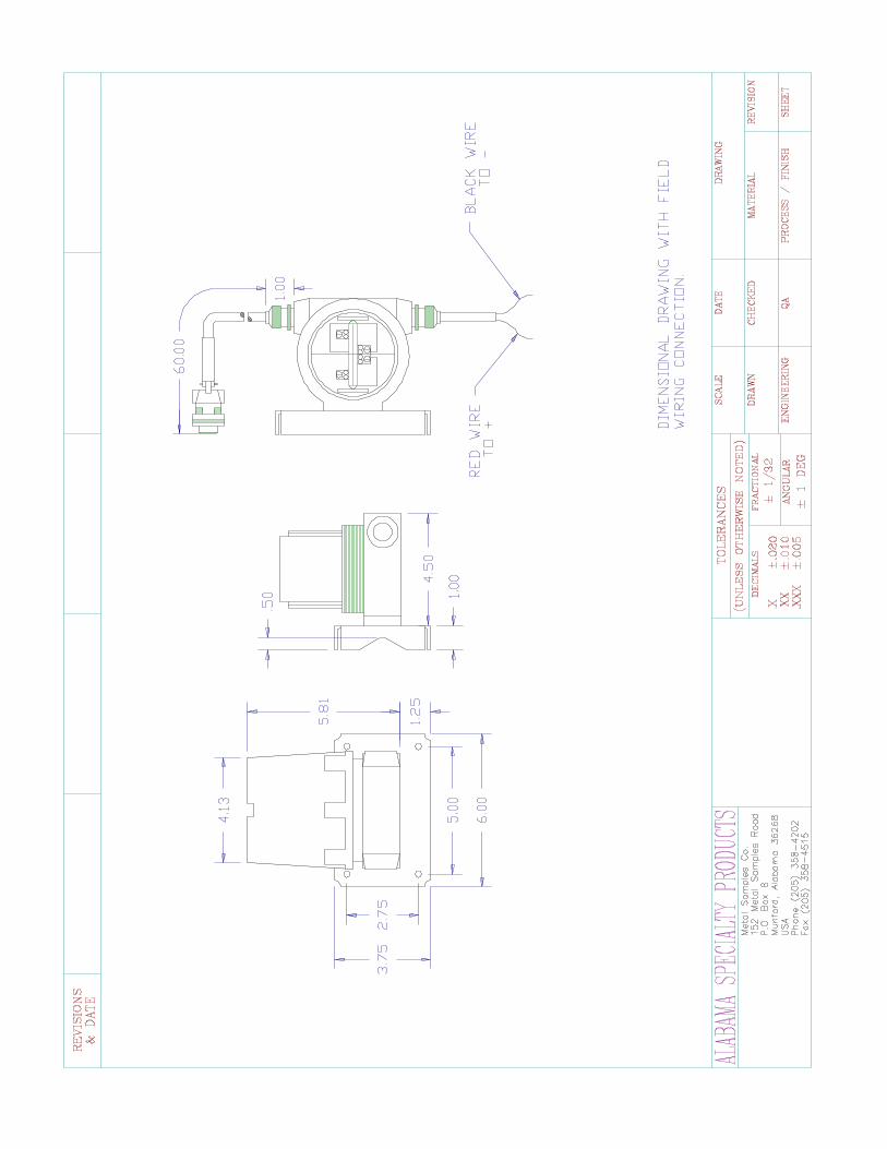
Physical DataInstrument Weight: 5.02 lb. (2.28 Kg)Total Weight w/ Accessories: 7.08 lb. (3.21 Kg)Instrument Dimensions: 5.81"H x 4.5"W x 4.81"D (14.76cm x 11.43cm x 12.22cm)
Case Specifications: Explosion Proof (FM, CSA, CENELEC, UL)Class I, Groups B, C, D, Class II, Groups E, F, G, Class III,CENELEC: Eexd IICNEMA 4X, 7BCD, 9EFG
Mounting Specifications: 0.728"H x 1.756"W (1.85cm x 4.46cm) Bolt Pattern with 1/4-20 Tapped Mounting Holes, or May Be Mounted on a 1/2" to2" (1.27cm to 5.08cm) Pipe Using Supplied Hardware
Operating Temperature: 0° to 140°F (-18° to 60°C)Storage Temperature: -40° to 176°F (-40° to 80°C)
Performance DataMeasurement Type: ER measurement using any standard ER probe type (Wire
Loop, Tube Loop, Cylindrical, Flush, Strip, etc.)Range: 0-100% of probe lifeResolution: 0.4% of Full ScaleCycle Time: 1 Minute
Electrical DataPower Requirements: 10 to 35 VDCMaximum Probe Cable Distance: 5 ft (1.52 m)Output Specifications: 4-20mA Current Loop OutputIntrinsic Safety: Certified to CAN/CSA
STD E9-0-95 & E79-11-95Class I, Division 1,Groups C and D, T4
Special Features• Switch selectable probe type (wire loop, tube loop, cylindrical, etc.)• Loop powered
Accessory Items5' Probe Cable (attached), Meter Prover, Mounting Hardware, Operation Manual

4
II. Installation and Operation
A. Receiving the MS2500E Transmitter
Check the MS2500E Transmitter for damage when it is first received. Obvious damage to theshipping carton should be brought to the attention of the responsible carrier’s agent.
When the MS2500E is unpacked, verify that the shipping carton contains the following items:
1. MS2500E Transmitter
2. 5' Cb-8140 Probe Cable (attached to housing)
3. Meter Prover
4. MS2500E Transmitter Operator’s Manual
B. Installation
Installation of the MS2500E Transmitter involves the following three procedures:
1. Mechanical Mounting
2. Electrical Connection
3. Calibration
Caution: If the transmitter is to be installed in a safe area, complete the three installation proce-dures in the order listed above. However, if the transmitter is to be installed in a hazardous area,complete the calibration procedure first; then follow with the mechanical mounting procedureand the electrical wiring procedure.
1. Mechanical Mounting
The MS2500E must be mounted on a flat surface connected to earth ground. Locate it within 5feet of the installed probe and connect the transmitter to the probe via Cb-8140 connectioncable. The transmitter will not function properly if cable other than Cb-8140 is used or ofextension cable is added.
Note: If the transmitter is to be located in a nonhazardous area, allow sufficient vertical clear-ance for the removal of the enclosure top so that wiring and calibration procedures can becompleted. See Drawing 1 for MS2500E dimensions.

5
Figure 1. Preferred Installation
2. Electrical Connection
The current loop cable used to connect the MS2500E Transmitter with its power supply must bea twisted pair, shielded, industrial gauge cable. The current loop cable enters the MS2500E viathe Transmitter’s 1/2-inch NPT access hole and is connected to the two loop connection termi-nals located within the Transmitter enclosure. Polarity is critical when attaching the cable to theMS2500E loop connection terminals. The loop connection terminals are easily accessed byunscrewing the top of the Transmitter’s enclosure.
Caution: Do not connect cable shielding to the Transmitter. The shield must remain floating atthe Transmitter.
The maximum permissible length of the current loop cable that connects the Transmitter and itspower supply is determined by the power supply voltage, the electrical resistance of the currentloop cable and the load of the receiver/CPU. If the Transmitter is to be installed in a safe area,refer to the paragraph Safe Area Wiring for details; if the Transmitter is to be installed in ahazardous area, refer to Hazardous Area Wiring instructions.

6
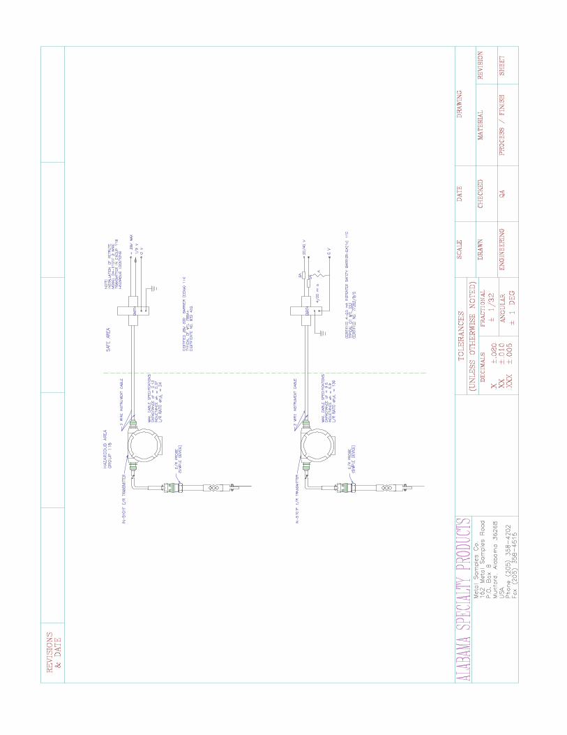
C. Safe Area Wiring
For basic safe area wiring information, refer to the circuit diagram shown in Drawing 2. Usethe following equation to determine maximum permissible cable length:
Where:
D = Max. cable length in feet.
VS = Power supply voltage.
R = Cable resistance in ohms per 1000 feet.
Example:
VS = 24 Volts
R = 16.1 (22 AWG cable)
D. Hazardous Area Wiring
Whenever an electrically driven sensor or measuring device is used in a potentially explosiveenvironment the measuring system must be installed in such a way that electrical energy iseither effectively isolated from the explosive environment (via explosive-proof containers,cable conduits, etc.) or the amount of electrical energy produced in the hazardous area must belimited to an intrinsically safe level.
Limiting electrical energy is the most practical method of protecting the MS2500E measuringsystem when the Transmitter is installed in a hazardous area. In the MS2500E system, electri-cal energy limits are maintained by the use of a repeater safety barrier (or its equivalent)installed in the 4-20 mA current loop per standard practice. The safety barrier must be locatedin the safe area near the boundary between the safe and hazardous areas. The safety barrier will
Vs - 10
(4 x 10⁻⁵) (R)D =
D =24 - 10
(4 x 10⁻⁵) (16.1)D = = 21,739 feet

7
repeat the signal current generated by the Transmitter and will relay the signal to the data receiv-ing station.
Caution: When a safety barrier is used with the MS2500E system, the current loop cable mustbe connected to the barrier’s hazardous area terminals. All other connections must be made tothe barrier’s safe area terminals.
The type of repeater safety barrier employed in the MS2500E system depends on the specificclassification of the hazardous environment in question. Metal Samples will provide, upon request,assistance and technical advice in the selection of a repeater safety barrier or its equivalent.
For most installations, Metal Samples recommends the intrinsically safe MTL 2441 Repeater PowerSupply.
The maximum length of the current loop cable that connects the MS2500E Transmitter to therepeater safety barrier is as follows:
Example:
17.5 Volts
22 AWG Cable = 5,434 feet maximum
16 AWG Cable = 21,788 feet maximum
1. Probe Selection Terminals
Housed within the MS2500E enclosure are probe selection terminals which correspond tospecific element types and which are used in the calibration procedure outlined below. Theprobe selection terminals permit the Transmitter to be used with all Metal Samples ER probes and withelectrical resistance probes available from other major manufacturers, regardless of probe element typeor element thickness.
2. Calibration
For routine calibration checks, a meter prover is provided. These units are factory calibratedbefore shipment and being solid potted exhibit no drift with time unless mechanically damaged.The meter prover is stamped with a three-digit number that represents percent of full scale (toone decimal place). Instruments should be checked against the meter every six months by dis-connecting the instrument probe cable from the probe and plugging the meter prover into theprobe cable connector. The instrument should be allowed to perform measurements on the
8
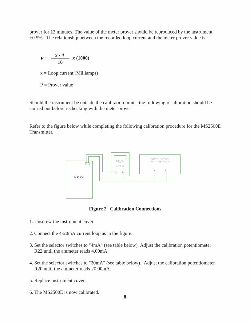
prover for 12 minutes. The value of the meter prover should be reproduced by the instrument±0.5%. The relationship between the recorded loop current and the meter prover value is:
x = Loop current (Milliamps)
P = Prover value
Should the instrument be outside the calibration limits, the following recalibration should becarried out before rechecking with the meter prover
Refer to the figure below while completing the following calibration procedure for the MS2500ETransmitter.
MS2500
Figure 2. Calibration Connections
1. Unscrew the instrument cover.
2. Connect the 4-20mA current loop as in the figure.
3. Set the selector switches to "4mA" (see table below). Adjust the calibration potentiometerR22 until the ammeter reads 4.00mA.
4. Set the selector switches to "20mA" (see table below). Adjust the calibration potentiometerR20 until the ammeter reads 20.00mA.
5. Replace instrument cover.
6. The MS2500E is now calibrated.
x (1000)P =x - 4
16

9
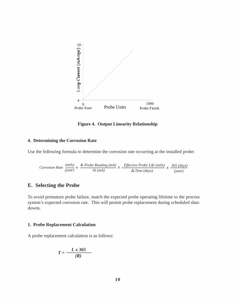
3. Operation
As shown in Figure 4, the transmitter output is linear. Initial Transmitter current output begins at4mA and increases to a maximum of 20mA. The maximum output of 20mA indicates that themeasuring element has been completely corroded and that the probe must be replaced.
Figure 3. Switch Locations and Orientation
2 1
TUBEWIRESPECTEST
R22 R20
F A
+ -
4-20mA LoopConnection
CalibrationPotentiometers
DigitalCircuit Board
Probe SelectionSwitch
Switches are UP
Switch is DOWN
* 20mA setting is illustrated in Figure 3 below.
10
0 10004
20
Probe Start Probe FinishProbe Units
Figure 4. Output Linearity Relationship
4. Determining the Corrosion Rate
Use the following formula to determine the corrosion rate occurring at the installed probe:
E. Selecting the Probe
To avoid premature probe failure, match the expected probe operating lifetime to the processsystem’s expected corrosion rate. This will permit probe replacement during scheduled shut-downs.
1. Probe Replacement Calculation
A probe replacement calculation is as follows:
T =L x 365
(R)
Corrosion Rate = x x(mils)(year) 16 (mA)
Probe Reading (mA) Effective Probe Life (mils)
Time (days)365 (days)
(year)
11
Where:
L = Effective life in mils.
R = Expected corrosion rate in mils per year.
T = Replacement period in days.
Since the initial estimation of expected corrosion rate prior to monitoring may be in error,definitely replace probe if transmitter output reaches 20 mA.
F. Maintenance
Once installed, the MS2500E does not require maintenance. However, if malfunctions occurwhich cannot be attributed to the data receiving station, power supply, or safety barrier, proceedas follows:
1. Ensure that the probe is operational and is not completely corroded.
2. Examine all electrical connections for proper electrical connections, signs of corrosion and toensure that the connections are environmentally protected.
3. Recalibrate the MS2500E Transmitter following the calibration procedure.
4. Contact Metal Samples for technical assistance if the Transmitter continues to malfunction followingrecalibration or if the Transmitter is obviously damaged. If advised to return the MS2500E for repair,follow the Instructions for Returning the Instrument for Repair.

12
G. Returning the Instrument for Repair
Complete the following procedures to ensure the fastest possible repair and return cycle:
1. If possible, pack the instrument in the original shipping carton. If the original carton is notavailable, pack the instrument in a rigid cardboard or wooden carton. Surround the instrumentwith a minimum of three inches of resilient packing material such as foam rubber or shreddednewspaper.
2. Ship the instrument prepaid via Air Freight or Air Express to:
Metal Samples152 Metal Samples RoadMunford, AL 36268
3. Contact Metal Samples by telephone (256) 358-4202 or by fax (256) 358-4515 and inform yoursales representative of:
a. the name of the airline carrying the instrument
b. the flight number
c. the estimated time of arrival
d. the waybill number and delivery instructions
4. When the instrument is packed, include a copy of the form on the next page, filled in asrequired, to expedite the repairs.

13
III. Maintenance and Repair Instructions
This form may be photocopied for use when returning instruments to Metal Samples for repair.Please fill in all known information. Enclose a copy of the filled in form with the instrument.
1. CHECK ONE:
Repair this instrument under warranty.
Repair this instrument regardless of problem or cost of repair.
Inspect the instrument and advise the customer of the approximate cost ofrepairs if the instrument is not covered under warranty. (Note - thisprocedure may delay the return of the instrument to you.)
2. INSTRUMENT IDENTIFICATION:
Instrument Model Number:
Serial Number:
Date of Purchase:
Company’s Purchase Order Number for Original Sale:
3. RETURN THE INSTRUMENT TO:
Company Name:

14
Address:
Telephone Number:
4. INVOICE INSTRUCTIONS:
5. DESCRIPTION OF TROUBLE:
(A clear description of the problem may shorten the repair time.)
6. URGENCY OF REPAIR:
Shipping Address:
Metal Samples152 Metal Samples RoadMunford, AL 36268

15
IV. Warranty Information
Metal Samples warrants that any part of the MS2500E and accessories which proves to be defectivein material or workmanship within one year of the date of original shipment to Purchaser will be repairedor replaced, at Metal Samples option, free of charge. This warranty does not cover (1) probe assem-blies, (2) items expendable in nature, or (3) items subject to damage from normal wear, misuse orabuse, or failure to follow use and care instructions.
All damaged items are to be shipped at Purchaser’s expense to and from Metal Samples which shallhave the right to final determination as to the existence and cause of a defect.
The foregoing shall constitute the sole and exclusive remedy of any purchaser of Metal Samples prod-ucts for breach of warranty and IS EXCLUSIVE AND IN LIEU OF ALL OTHER WARRANTIES,EXPRESSED, IMPLIED OR STATUTORY, INCLUDING THE IMPLIED WARRANTIES ORMERCHANTABILITY AND FITNESS. IN NO EVENT SHALL METAL SAMPLES BE LIABLEFOR SPECIAL OR CONSEQUENTIAL DAMAGES, OR FOR ANY DELAY IN THE PERFOR-MANCE OF THIS WARRANTY DUE TO CAUSES BEYOND ITS CONTROL.
Orders or request for additional information should be addressed to:
Metal SamplesP.O. Box 8Munford, AL 36268Telephone: (256) 358-4202Fax: (256) 358-4515
The technical information and suggestions contained herein are believed to be reliable, but theyare not to be construed as warranties since conditions of use are beyond our control.
Shipping Address
Metal Samples152 Metal Samples RoadMunford, AL 36268Telephone: (256) 358-4202Fax: (256) 358-4515