MS05-50 pp63-67 20/5/05 5:04 pm Page 63 RAW MATERIALS...
5
AUTHORS: Reinoud J van Laar and Ton A Spiering Danieli Corus BV D uring normal operation the blast furnace bottom and hearth contains the ‘dead-man’ and the salamander. The salamander includes liquid iron and slag and mixtures of solid iron, slag and coke/carbon. These bottom and hearth constituents must be evacuated when relining the blast furnace and it is also recommended to evacuate the liquid salamander prior to partial relines and taphole repairs. This provides safer working conditions and prevents damage to the hearth refractories as a result of cyclic cooling and heating movements. However, a solid salamander is usually difficult to remove – especially if titanium is present – and a large solid salamander can delay the critical path of the project by several days or even weeks. Dynamiting and oxygen lancing may often be required, causing health and safety hazards, thus it is important to maximise the yield of the salamander tap. The liquid salamander (see Figure 1) is normally tapped immediately after the blow-down. It is important to maximise the yield of the salamander tap in order to minimise the tonnage of the residual solids and thus minimise delays. A successful salamander tapping also Successful tapping of the salamander prior to blast furnace rebuilds or major outages leads to shorter outage times and safer working conditions. Blast furnace pre-preparation and monitoring to increase temperature and fluidity, coupled with the use of well-tried drilling and lancing techniques, can achieve total salamander removal. Tapping the blast furnace salamander RAW MATERIALS AND IRONMAKING a 63 MILLENNIUM STEEL 2005 contributes to safer working conditions during the demolition and it generally inspires the reline team’s spirit. Salamander tapping considerations will be discussed in this paper and exemplified by successful results achieved at POSCO in March 2005. INTRODUCTION There are several prerequisites for successful salamander tapping. These include a maximum ratio between liquid and solid salamander, low viscosity/high temperature of the liquids, correct setting of the salamander tapping angle(s) and elevation(s), good blow-down results, and efficient execution of the actual salamander tapping activities. Quenching of the remaining burden and refractories is equally important in securing safe working conditions and accelerating the reline project. The preparations for the salamander tapping start 3–6 months prior to the reline and include actual salamander tapping activities and process modifications. SALAMANDER LIQUEFACTION The process modifications must result in favourable conditions for optimum salamander tapping. One of the main targets relates to melting/liquefaction of the q Fig.1 Salamander tapping
Transcript of MS05-50 pp63-67 20/5/05 5:04 pm Page 63 RAW MATERIALS...

AUTHORS: Reinoud J van Laar and Ton A SpieringDanieli Corus BV
During normal operation the blast furnace bottomand hearth contains the ‘dead-man’ and the
salamander. The salamander includes liquid iron and slagand mixtures of solid iron, slag and coke/carbon. Thesebottom and hearth constituents must be evacuated whenrelining the blast furnace and it is also recommended toevacuate the liquid salamander prior to partial relines andtaphole repairs. This provides safer working conditionsand prevents damage to the hearth refractories as a resultof cyclic cooling and heating movements.
However, a solid salamander is usually difficult toremove – especially if titanium is present – and a largesolid salamander can delay the critical path of the projectby several days or even weeks. Dynamiting and oxygenlancing may often be required, causing health and safetyhazards, thus it is important to maximise the yield of thesalamander tap.
The liquid salamander (see Figure 1) is normally tappedimmediately after the blow-down. It is important tomaximise the yield of the salamander tap in order tominimise the tonnage of the residual solids and thusminimise delays. A successful salamander tapping also
Successful tapping of the salamander prior to blast furnace rebuilds or major outages leads toshorter outage times and safer working conditions. Blast furnace pre-preparation and monitoring to increase temperature and fluidity, coupled with the use of well-tried drilling and lancingtechniques, can achieve total salamander removal.
Tapping the blast furnace salamander
RAW MATERIALS AND IRONMAKING
a
63
MIL
LEN
NIU
M S
TEEL
2005
contributes to safer working conditions during thedemolition and it generally inspires the reline team’s spirit.
Salamander tapping considerations will be discussed inthis paper and exemplified by successful results achievedat POSCO in March 2005.
INTRODUCTIONThere are several prerequisites for successful salamandertapping. These include a maximum ratio between liquidand solid salamander, low viscosity/high temperature ofthe liquids, correct setting of the salamander tappingangle(s) and elevation(s), good blow-down results, andefficient execution of the actual salamander tappingactivities.
Quenching of the remaining burden and refractories isequally important in securing safe working conditionsand accelerating the reline project. The preparations forthe salamander tapping start 3–6 months prior to thereline and include actual salamander tapping activitiesand process modifications.
SALAMANDER LIQUEFACTIONThe process modifications must result in favourableconditions for optimum salamander tapping. One of themain targets relates to melting/liquefaction of the
q Fig.1Salamandertapping
MS05-50 pp63-67 20/5/05 5:04 pm Page 63
MIL
LEN
NIU
M S
TEEL
2005
64
will be indicative of the thermal state of the hearth.Salamander liquefaction is thus basically the opposite of
hearth protection for campaign extension and since thereis much more agreement on campaign extension issuesthan on salamander liquefaction, it is worthwhilecomparing both.
Typical liquefaction methodologies include:
` Reduce bottom and sidewall cooling` Target high productivity` Implement tapping between alternating tapholes` Increase silicon to 0.5–0.6%` Charge coarse coke` Terminate charging of TiO2
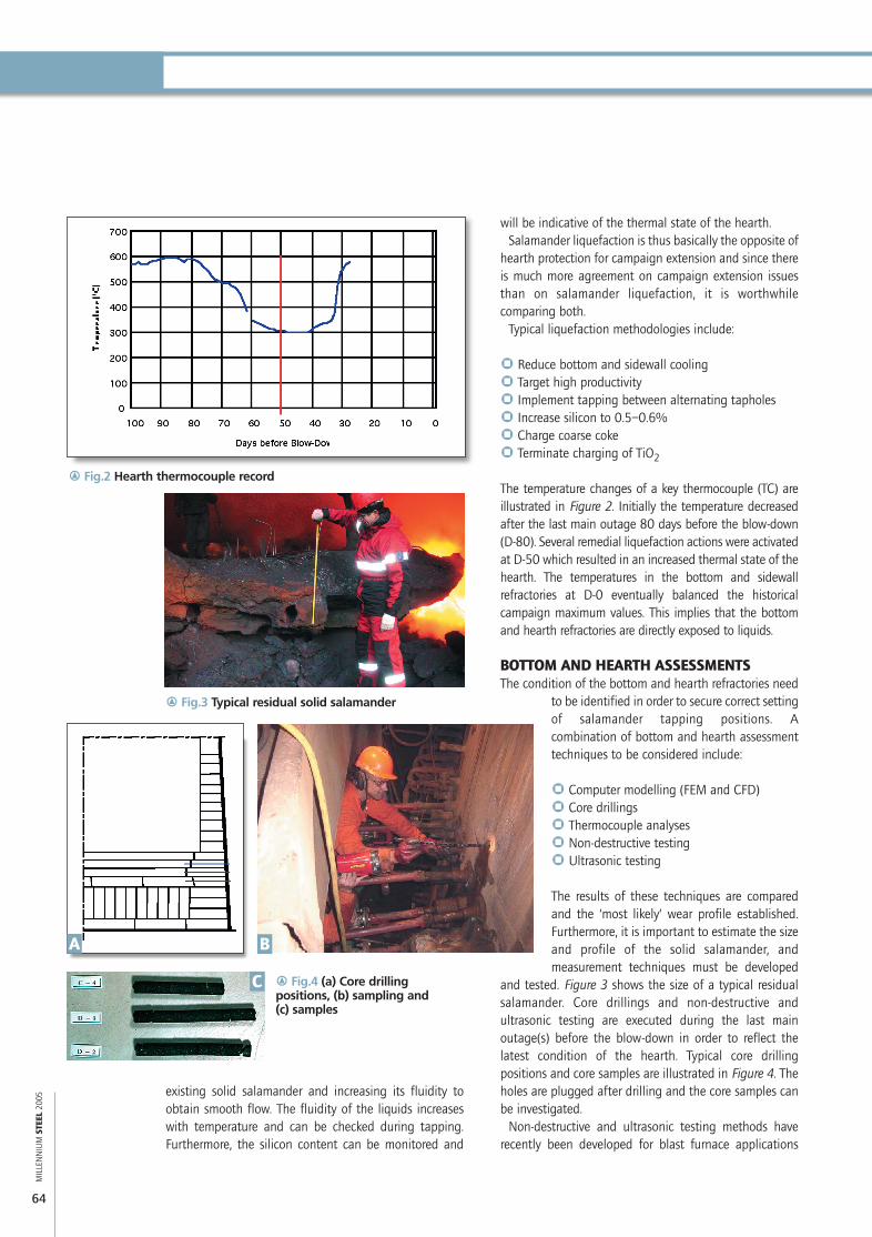
The temperature changes of a key thermocouple (TC) areillustrated in Figure 2. Initially the temperature decreasedafter the last main outage 80 days before the blow-down(D-80). Several remedial liquefaction actions were activatedat D-50 which resulted in an increased thermal state of thehearth. The temperatures in the bottom and sidewallrefractories at D-0 eventually balanced the historicalcampaign maximum values. This implies that the bottomand hearth refractories are directly exposed to liquids.
BOTTOM AND HEARTH ASSESSMENTSThe condition of the bottom and hearth refractories need
to be identified in order to secure correct settingof salamander tapping positions. Acombination of bottom and hearth assessmenttechniques to be considered include:
` Computer modelling (FEM and CFD)` Core drillings` Thermocouple analyses` Non-destructive testing` Ultrasonic testing
The results of these techniques are comparedand the ‘most likely’ wear profile established.Furthermore, it is important to estimate the sizeand profile of the solid salamander, andmeasurement techniques must be developed
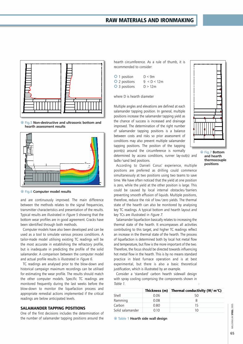
and tested. Figure 3 shows the size of a typical residualsalamander. Core drillings and non-destructive andultrasonic testing are executed during the last mainoutage(s) before the blow-down in order to reflect thelatest condition of the hearth. Typical core drillingpositions and core samples are illustrated in Figure 4. Theholes are plugged after drilling and the core samples canbe investigated.
Non-destructive and ultrasonic testing methods haverecently been developed for blast furnace applications
existing solid salamander and increasing its fluidity toobtain smooth flow. The fluidity of the liquids increaseswith temperature and can be checked during tapping.Furthermore, the silicon content can be monitored and
r Fig.2 Hearth thermocouple record
r Fig.3 Typical residual solid salamander
r Fig.4 (a) Core drillingpositions, (b) sampling and (c) samples
A
C
B
MS05-50 pp63-67 20/5/05 5:05 pm Page 64
65
and are continuously improved. The main differencebetween the methods relates to the signal frequencies,transmitter characteristics and presentation of the results.Typical results are illustrated in Figure 5 showing that thebottom wear profiles are in good agreement. Cracks havebeen identified through both methods.
Computer models have also been developed and can beused as a tool to simulate various process conditions. Atailor-made model utilising existing TC readings will bethe most accurate in establishing the refractory profile,but is inadequate in predicting the profile of the solidsalamander. A comparison between the computer modeland actual profile results is illustrated in Figure 6.
TC readings are analysed prior to the blow-down andhistorical campaign maximum recordings can be utilisedfor estimating the wear profile. The results should matchthe other computer models. Specific TC readings aremonitored frequently during the last weeks before theblow-down to monitor the liquefaction process andappropriate remedial actions implemented if the criticalreadings are below anticipated levels.
SALAMANDER TAPPING POSITIONSOne of the first decisions includes the determination ofthe number of salamander tapping positions around the
MIL
LEN
NIU
M S
TEEL
2005
RAW MATERIALS AND IRONMAKING
a
hearth circumference. As a rule of thumb, it isrecommended to consider:
` 1 position D < 9m` 2 positions 9 < D < 12m` 3 positions D > 12m
where D is hearth diameter
Multiple angles and elevations are defined at eachsalamander tapping position. In general, multiplepositions increase the salamander tapping yield asthe chance of success is increased and drainageimproved. The determination of the right numberof salamander tapping positions is a balancebetween costs and risks so prior assessment ofconditions may also prevent multiple salamandertapping positions. The position of the tappingpoint(s) around the circumference is normallydetermined by access conditions, runner lay-out(s) andladle/sand bed positions.
According to Danieli Corus’ experience, multiplepositions are preferred as drilling could commencesimultaneously at two positions using two teams to savetime. We have often noticed that the yield at one positionis zero, while the yield at the other position is large. Thiscould be caused by local internal obstacles/barrierspreventing smooth effusion of liquids. Multiple positions,therefore, reduce the risk of low/zero yields. The thermalstate of the hearth can also be monitored by analysingkey TC readings. A typical bottom and hearth layout andkey TCs are illustrated in Figure 7.
Salamander liquefaction basically relates to increasing thethermal state of the hearth. It encompasses all activitiescontributing to this target, and higher TC readings reflectan increase in the thermal state of the hearth. The processof liquefaction is determined both by local hot metal flowand temperature, but flow is the more important of the two.Therefore, the focus should be directed towards influencinghot metal flow in the hearth. This is by no means standardpractice in blast furnace operation and is at bestexperimental, but there is also a basic theoreticaljustification, which is illustrated by an example.
Consider a ‘standard’ carbon hearth sidewall designwith spray cooling comprising the components shown inTable 1.
Thickness (m) Thermal conductivity (W/m°C)Shell 0.06 50Ramming 0.08 8Carbon 0.80 15Solid salamander 0.10 10
r Fig.6 Computer model results
r Table 1 Hearth side wall design
r Fig.7 Bottomand hearththermocouplepositions
r Fig.5 Non-destructive and ultrasonic bottom andhearth assessment results
MS05-50 pp63-67 20/5/05 5:07 pm Page 65

MIL
LEN
NIU
M S
TEEL
2005
66
The lowest elevation and angle should first be used, thenthe second elevation and angle if the first drilling isunsatisfactorily, etc. The entire salamander tappingprocess should be executed within ~24 hours: it isimportant to establish clear ‘go-stop’ criteria to ensure thatdelays are prevented. For example, we recommend amaximum of 4 hours drilling and lancing one hole,irrespective of success. This requires specialised andexperienced teams.
The vertical distance between holes should be ~300mmto ascertain that the holes do not merge as effusion ofliquids will increase the diameter of the ‘successful’ hole. Atypical hole drilling diameter is ~80mm and couldincrease to >200mm during tapping. The minimumdistance between two holes will thus ensure that the holesstay intact. We limit the salamander tapping length tothree metres as it is our experience that the holes may beclogged during tapping if the length is too great.
DRILLING METHODOLOGIESThere is a wide variety of drilling equipment. Basically,two types are distinguished:
` Monorail, mounted type` Runner, manual type
It is recommended to use the manual type drillingequipment to maximise flexibility in setting angle(s) andelevation(s) while minimising costs. There are severalmanual types, for example rock-drill and core-drill. DanieliCorus recommends utilising a core-drill type, which can bebetter aligned and has an increased accuracy. It isrecommended to allocate the power and control unitoutside the runner to maximise safety. The drill unit ismounted on a small rail, which is ‘hooked’ or welded tothe shell and supported by the runner.
The field layout of this equipment is shown in Figure10. Two people operate the equipment and onesupervisor normally monitors activities. Drilling of onehole approximately 2m in length, normally takes aboutone hour. Interim temperature measurements should bemade to control the drilling process.
Re-allocating the manual type to another point (higherelevation and increased angle) can be done inapproximately one hour. Oxygen lancing (see Figure 11) isnearly always required as drilling should be haltedtimeously. It is recommended to halt drilling attemperatures of ~800ºC to allow for safe removal of thedrilling equipment otherwise drilling will automatically behalted once the drill bit melts at higher temperatures dueto friction heat-up. This is especially important when thebottom and hearth refractories are re-used and damageshould be limited. In such a situation, oxygen lancing
Each lining component and the solid salamanderare characterised by a thermal resistance. An extrathermal resistance is introduced by the heattransfer coefficient between the liquids and thehot face of the lining, which is related to the squareroot of the iron velocity. The hot face temperatureof the carbon versus hot metal velocity can becalculated for a constant hot metal temperature.The hot face temperature of the carbon versus thehot metal temperature for a constant hot metalvelocity can also be calculated. The results areillustrated in Figure 8 where the red line is metalvelocity and the blue line is hot metal temperature.
The hot face temperature of the carbon decreasesrapidly for lower metal velocities and is onlyslightly affected by the hot metal temperature. Thismeans that the hot metal temperature is arelatively ineffective tool in establishing a higher
thermal state of the hearth. Lower hot metal velocities atthe bottom and hearth sidewall should be prevented asthey result in a very low thermal state of the hearth, andwill thus jeopardise the salamander tapping process.
The correct setting of the salamander tapping anglesand elevations is normally a compromise betweentheoretical calculations and considerations, and practicallimits. Structural elements on site such as piping andcabling may limit access conditions and the elevation(s)of the ladle track(s) may inhibit selection of the mostoptimum theoretical salamander tapping elevation.
Danieli Corus normally considers at least three sets ofincreasing angles and elevations at each salamandertapping position (see Figure 9). It is common practice todetermine two or three angles and elevations at eachcircumferential salamander tapping position. The verticaldistance between the starting points is ~300mm.
r Fig.8 Liquefaction parameters
r Fig.9 Typicalsalamandertappingangles andelevations
MS05-50 pp63-67 20/5/05 5:08 pm Page 66

67
which has allowed us to establish general methodologies tomaximise the quantity of salamander tapping andminimise risks.
Most recently, successful salamander tapping of POSCOGwangyang No.2 BF, South Korea, allowed for a completedemolition of the BF, from top dome to bottom coolingsystem, in 16 days as no residual salamander was left. Thiscould be considered a world record and would not havebeen achieved if a salamander remained.
It is acknowledged that plant experiences and historiesare also crucial in achieving high yields and it isrecommended that tailor-made procedures be establishedfor each project based on mutual understanding andagreement of the requirements and methodologies.Operational optimisation with regard to liquefaction ofthe solid salamander increases the yield significantly. Re-pressurising the blast furnace during salamander tappingalso contributes to a higher yield.
The effects of the salamander tapping can be furtherenhanced by considering quenching of the residualhearth materials in order to accelerate cool-down of theblast furnace. In general, Danieli Corus prefers to combinesalamander tapping and quenching to provide the bestconditions for a successful repair outage and eliminate allrisks. Alternatively, hearth residuals can be cooled downby means of spray lances through the tuyeres.
ACKNOWLEDGEMENTSThe author wishes to acknowledge Cho Bong-Rae, KimGap Yeol and Gyoung-Yoen Son of POSCO for theirexcellent cooperation in and approval of this paper.Furthermore, the author wishes to express his appreciationto Maarten Geerdes and Leo Heida for their supportduring last year’s salamander tapping project. MS
Reinoud J.van Laar is Engineering Technologist and TonA Spiering is Consultant Blast Furnace Operations, bothat Danieli Corus BV, IJmuiden, The Netherlands
CONTACT: [email protected]
MIL
LEN
NIU
M S
TEEL
2005
duration should be limited to one hour ateach hole to prevent large cavities forming.
Salamander drilling of two holes wascompleted within two hours at oneposition at POSCO and 15 minutes oxygenlancing was applied: salamander drillingof one hole at the opposite side resulted inhot metal liquids flow within two hoursand without lancing.
SEQUENCE OF EVENTSThe salamander tapping activities include:
` Removal of plate` Install ramming` Dry-out ramming` Set-up drilling equipment` Salamander drilling` Oxygen lancing` Salamander tapping
The salamander tapping activities are on the critical pathof the reline and can normally be executed within 24hours. The duration is mainly determined by the numberof circumferential positions and associated labour crews.Repetitive drilling and oxygen lancing may be required.The typical duration for the above-mentioned activities islimited to 12 hours. Sometimes, pre-drilling is practisedduring the pre-outage, but it is our experience that thisdoes not contribute to accelerating the salamandertapping activities during the reline. Installation oframming at the runner/shell interface and subsequentdry-out may be eliminated if a correct design is appliedand associated works are executed during the pre-outage.
The set-up of the drilling equipment, salamander drilling,oxygen lancing and start of the salamander tapping wasless than three hours during our last project at POSCO.More than 1,000t was tapped in 5 hours and the quenchcould start within 12 hours after the end of the blow-down.This schedule was only achievable because all preparationsand conditions had been optimised and synchronised.
CONCLUSIONSSalamander tapping is a critical project activity during anyreline and repair project. A successful salamander tapping– resulting in a high yield of liquids removed beforequenching and a low weight of solid residuals – preventslong delays and improves health and safety conditionsduring demolition. Therefore, it is important to ensurethat all available techniques and experiences areinvestigated and utilised.
Since the early 1980s, Danieli Corus has gained vastexperience in worldwide salamander tapping projects
RAW MATERIALS AND IRONMAKING
r Fig.10 Field layout of salamander drilling equipment r Fig.11 Oxygenlancing
MS05-50 pp63-67 20/5/05 5:09 pm Page 67