MS Incremental Magnetic Scales - RLS
30
® DATA SHEET MSD01_01 Issue 01, 3 rd December 2020 The robust MS incremental magnetic scales consist of a stainless steel carrier and an elastomer-bonded ferrite. The elasto-ferrite layer is magnetised with 2 mm, 2.032 mm or 5 mm long alternating magnetic poles that form an incremental magnetic pattern. Features and benefits MS Incremental Magnetic Scales ⯈ Customer selectable position of reference mark ⯈ Four accuracy grades available: ±10 μm/m, ±20 μm/m, ±40 μm/m, ±100 μm/m ⯈ Partial arc application possibility ⯈ Optional protective cover foil for heavy duty applications ⯈ Excellent resistance to dirt, dust and humidity ⯈ Easy installation with adhesive tape, end clamps or track section ACCURACY UP TO ±10 µm/m DISTANCE CODED REFERENCE MARK UP TO 150 m LENGTH PRINTING TECHNOLOGY SMT PICK AND PLACE INDUSTRIAL AUTOMATION ASSEMBLY LINES LINEAR MOTOR
Transcript of MS Incremental Magnetic Scales - RLS

®DATA SHEETMSD01_01Issue 01, 3rd December 2020
The robust MS incremental magnetic scales consist of a stainless steel carrier and an elastomer-bonded ferrite. The elasto-ferrite layer is magnetised with 2 mm, 2.032 mm or 5 mm long alternating magnetic poles that form an incremental magnetic pattern.
Features and benefits
MSIncrementalMagnetic Scales
⯈ Customer selectable position of reference mark
⯈ Four accuracy grades available: ±10 μm/m, ±20 μm/m, ±40 μm/m, ±100 μm/m
⯈ Partial arc application possibility
⯈ Optional protective cover foil for heavy duty applications
⯈ Excellent resistance to dirt, dust and humidity
⯈ Easy installation with adhesive tape, end clamps or track section
ACCURACY UP TO ±10 µm/m
DISTANCE CODED
REFERENCE MARK
UP TO 150 m LENGTH
PRINTING TECHNOLOGYSMT PICK AND PLACE INDUSTRIAL AUTOMATION ASSEMBLY LINESLINEAR MOTOR

The incremental RLS magnetic scales are compatible with RLS standard LM and component level RoLin readheads, which ensure reliable operation due to the non-contact design.
For readhead specifications see data sheets available at RLS media center.
Selection guide
Scale
Pole length[mm]
Scale width [mm]
Accuracy[μm/m]
Compatibility with readheads
LM10 LM13 LM15 RLB2 RLC2HD RLC2IC RLM2
MS05 2 5 ±10 / ±20 / ±40 - - - No Ri No Ri Ri+DCRM Ri+DCRM
MS07 2.032 5 ±40 - - - - - - Ri*
MS10 2 10 ±10 / ±20 / ±40 Ri+DCRM Ri+DCRM - No Ri No Ri Ri+DCRM Ri+DCRM
MS12 2.032 10 ±40 Ri* Ri* - - - - -
MS15 5 10 ±100 - - Ri+DCRM - - - -
Ri - Unique and multiple reference mark or only incremental track availableNo Ri - No unique and multiple reference mark option, only incremental track availableRi+DCRM - Unique, multiple, distance-coded reference mark or only incremental track available
* Compatible with DPI version only.
Pole length
Scalewidth
General information
2
DATA SHEETMSD01_01

>75 mm
N S
Storage and handling
PackagingThe type of packaging depends on both the length of the magnetic scale and its accuracy class. Shorter scales are packed individually, while scales with a longer length are rolled.
To maintain accuracy, special packaging is used for magnetic scales of accuracy class D; Scales shorter than 1 m are packed in a plastic tube, while spiral packaging is used for longer lengths. This prevents demagnetisation of the scale by maintaining the distance between the scale rolls.
If option B, H or N is selected, the protective cover foil is supplied together with the scale. The cover foil is not mounted on the scale.
All MS magnetic scales have 12 months shelf life and should be installed within this period.
Chemical resistanceThe use of alcohol for cleaning is considered safe, but it is not allowed to immerse the scale in alcohol. Furthermore, the scale surface print and drawn reference mark may disappear if the scale is not carefully cleaned.
For more information on chemical resistance contact RLS.
Storage temperature Operating temperature
–40 °C to +60 °C
Scale applied on the linear guide: –40 to +100 °C
Scale applied on the curved surface: –40 °C to +80°C
Up to 100 % RH
Humidity
It is strongly recommended that the scale is factory cut at RLS otherwise product warranty does not apply.
The magnetic scale should not be exposed to magnetic field densities higher than 50 mT on its surface, as this can damage the scale.
3
®
A associate company

Overall errorScale errorSDENoise
Magnetisation errorThe magnetisation error is caused by imperfections in the elasto-ferrite material and possible deviations resulting from the magnetisation process.
The following factors influence the result:
• Magnetic inhomogeneity of the elasto-ferrite layer,• Oscillations in the elasto-ferrite thickness,• Measurement uncertainty of the magnetisation system
during manufacturing process
Sub-divisional error (SDE)The sub-divisional or interpolation error is a periodic accuracy error. It is influenced by the following factors:
• Inhomogeneity and cycle definition of magnetic poles,• Sensing distance (ride height) of the installed readhead,• Quality of signal processing,• Properties of the sensor.
The SDE leads to speed undulations in applications where the encoder is used as a feedback, e.g. in speed control loops.
HysteresisHysteresis is a difference in the measurement results when approaching the same point from different directions. The ferromagnetic materials maintain the magnetised state in response to external fields and try to change their direction. Hysteresis in the encoder systems depends on the magnetic field strength. A stronger magnetic field leads to a smaller hysteresis and vice versa. Therefore hysteresis is strongly influenced by the sensing distance at which the readhead is installed.
Typical error plot representation.
Encoder-specific errorsThe accuracy of the linear encoder measurement is influenced by the encoder-specific errors and the installation-dependent error. To evaluate the overall accuracy, each of the significant errors must be taken into account.
The accuracy class is a sum of Sub-Divisional Error (SDE) and magnetisation error. The extreme values of the measurement curves over any one-meter section of the measuring length are within the accuracy class, as shown on the right. If measuring length is shorter than one meter, the accuracy class corresponds to this length. Magnetic scales are produced in four accuracy classes:
⦁ Class D: ±10 μm/m ⦁ Class A: ±20 μm/m ⦁ Class B: ±40 μm/m ⦁ Class C: ±100 μm/m
For accuracy class D (±10 µm/m) a special packaging is provided to ensure the performance of the scale (see Packaging). Example for accuracy class A.
Representation of a Hysteresis as a function of ride height (for 2 mm pole length only).
Representation of an SDE as a function of the ride height.
Erro
r [µm
]
Position [mm]
Erro
r [µm
]
Position [m]2 2.5 3.51.5 3 4
±20 μm
1 m
Hys
tere
sis
[µm
]
Ride height [mm]
30
20
10
40
0 0.4 0.6 1.41.0 1.60.2 0.8 1.2
SDE
[µm
]
Ride height [mm]
20
10
30
0 0.4 0.6 1.41.0 1.60.2 0.8 1.2
-2 0 1 53 6-1 2 4
0
30
20
10
40
50
All figures below are for representation purpose only.
0
30
20
10
–10
–20
–30
Guaranteed SDEMeasured SDE
Accuracy of linear encoder systems
4
DATA SHEETMSD01_01

ABBE ERROR = tan(Θ) * offset ABBE ERROR
Offset
Angle Θ
Reported movement
Actual movement
Scale length LS
L = LS cos θ
Scale axis
Axis of travel
θ
Measured length L
Installation and temperature-dependent errorsIn addition to the given encoder-specific error, the installation of the encoder system has a considerable influence on the total accuracy of the encoder system. Of particular importance are the installation eccentricity and the effect of deformations caused by scale installation.
Temperature-dependent errorTemperature-dependent error is an effect of a thermal expansion coefficient α that can be used to calculate the thermal expansion coefficient (CTE) ΔL
where L is an effective length of the magnetic scale in [m] and ΔT is a relative temperature difference in [K]. RLS offers steel with CTE ΔL = 17 x 106 [m/mK].
Influence of stress during installationThe accuracy of the system is influenced by the repeated cycling of the load. The tensile load of 1 kg causes the magnetic scale to expand for 17 μm. The linear expansion ΔL can be calculated as
where F is tensile force in [N], A cross-sectional area in [m2], E Young’s modulus of elasticity in [Pa] and L scale length in [m].
Abbe or sine errorAbbe or sine error occurs when the axis of measurement is offset from the axis to be measured. If the axis of linear movement is curved, the difference between the actual movement and the reported movement contains an error proportional to the offset and the tangent of the angle θ.
ΔL = L . α . ΔT
ΔL = A . E
FL
Cosine errorThe cosine error results from an angular offset between the axis of motion and the position-giving element (encoder). The cosine error is as small as the angle θ.
5
®
A associate company

®
OPTIONAL: Cover foil and double-sided adhesive tape
OPTIONAL: VHB Double-sided acrylic adhesive tape
Magnetic layer and stainless steel carrier
Structure
Appearance and print
Scale surface print description
MS 10 B / A WW YY BB NNN
Scale type
Accuracy class
Back adhesive options Week of scale production
Year of scale production
Batch number
Counter designator(100 mm = +1 count)Magnetic scale
Magnetic field viewerIncremental track
Reference mark
The shape of the reference mark may vary. The image is for representation purposes only.
The orientation of the magnetised reference mark and the incremantal track is always the same, relative to the scale print as shown in the figure below.
Scale surface print appears every 100 mm and contains the RLS logo and a unique code.
Magnetic scale designDimensions and tolerances are in mm.
6
DATA SHEETMSD01_01

Technical specifications
System dataPole length 2 mm, 2.032 mm, 5 mm
Reference mark Unique, DCRM, multiple reference marks
Scale accuracy Class A ±20 µm/m
Class B ±40 µm/m
Class C ±100 µm/m
Class D ±10 µm/m
Mechanical dataMaterial Carrier 1.4310 stainless steel
Magnetic scale NBR elasto-ferrite
Thickness Carrier 0.3 ±0.05 mm
Double-sided acrylic adhesive tape VHB 3M9469
0.13 mm
Cover foil 0.076 ±0.006 mm
Double sided tape 0.05 mm
Scale 1.43 ±0.1 mm (with back adhesive)1.3 ±0.1 mm (without back adhesive)
Mass MS05, MS07 0.031 kg/m
MS10, MS12, MS15 0.062 kg/m
Width MS05, MS07 5 mm
MS10, MS12, MS15 10 mm
Cover foil width CF05 (MS05, MS07) 4.8 ±0.35 mm
CF08 (MS10, MS12, MS15) 7.6 ±0.35 mm
CF10 (MS10, MS12, MS15) 9.5 ±0.1 mm
Maximum length Accuracy class A, B, C 50 m (150 m with longer lead time*)
Accuracy class D 20 m
Expansion coefficient (carrier) ~17 × 10-6 [m/mK]
Minimum bending radius 75 mm
* Not applicable for MS05 and MS07.
Environmental dataTemperature Operating Scale applied on the linear guide: –40 °C to +100 °C
Scale applied on the curved surface: –40 °C to +80 °C
Storage –40 °C to +60 °C
–0.05 +0.15
–0.05 +0.15
7
®
A associate company

Distance coded reference marks (DCRM)The readhead must be ordered with reference mark option A (see corresponding readhead data sheet). The magnetic scale must be ordered with a reference mark option D and a basic increment value stated as K (see Part numbering). The distance coded reference mark option provides multiple magnetised reference marks that are individually spaced according to a specific mathematical algorithm. The absolute position is calculated after traversing 2 consecutive reference marks. Maximum length and minimum traverse depend on basic spacing (K) between reference marks, as shown in the figure below. which is customer selectable at point of order.
Multiple reference markThe readhead must be ordered with reference mark option A (see corresponding readhead data sheet). The magnetic scale must be ordered with reference mark option P (see Part numbering). Multiple reference marks are magnetised, factory predefined and spaced every 50, 100, or 200 mm on a 20 m long scale. For custom options please contact RLS.
Unique reference mark The readhead must be ordered with reference mark option A (see corresponding readhead data sheet). The magnetic scale must be ordered with reference mark (see Part numbering). If required, the cover foil can be installed over the reference mark. See below table of default reference marks for each magnetic scale. MS10 can also be ordered with magnetised reference mark (see Part numbering for Reference mark option M).
The shape and the position of the cut or magnetised reference mark are critical so these options are only available as factory order.
Cut reference mark Magnetised reference mark
Scale Default reference mark
MS05 magnetised
MS07 magnetised
MS10 cut
MS12 cut
MS15 magnetised
Reference mark options
The basic increment K (in mm) is chosen at the point of order and must be divisible by 2 × P with no remainder. K determines:Maximum codable length:
Minimum distance along the measuring scale which needs to be traversed in order to calculate the absolute position. The minimum travel distance equals the basic increment K - 2P.
Lmax - Maximum codable length (in mm)K - Basic increment (in mm)P - Pole length (in mm)
2P12PΚ
Lmax −
−=Κ
8
DATA SHEETMSD01_01

K
K/2 + 2 mm
K + 2 mmLmax
K + 2 mm
K
K/2 - 2 mm K/2 + 4 mm K/2 - 4 mm K/2 + 6 mmK + 2 mm
K - 4 mm *6 mm
K/2
MS10A/A-WWYY-BB-2000-NNN
* Depends on magnetic scale length.
The distribution of the reference marks is shown in the figure below. DCRMs are produced by additional magnetisation of the magnetic scale.
K (mm)Maximum codable length (mm)
P = 2 mm P = 5 mm
20 76
40 356
60 836
80 1,516
100 2,396 890
200 9,796 3,790
300 22,196 8,690
400 39,596 15,590
500 61,996 24,490
600 89,396 35,390
700 48,290
800 63,190
900 80,090
1,000 98,990
( ) ( ) ( ) ( ) )[ ] (2
sgn2sgn2
12sgn211 RIabsDKRIKKRIKRIabsP
RI ∆×−−∆×+×
−−∆×−−∆××=
How the absolute position is evaluated
The absolute position of the first traversed reference mark is calculated by the following formula:
Basic increment (K in mm) - Represents the distance in mm between odd reference marks; it determines the maximum codable length over which the absolute position can be defined. It also determines the minimum distance which needs to be traversed to capture 2 neighbouring reference marks. The basic distance should be divisible by the length of 2 poles (in mm). K is customer selectable.
Maximum codable length (Lmax in mm) - Is the maximum length of the magnetic scale over which the DCRM feature can be applied and still provide a unique absolute position. Lengths shorter than the maximum length can also be used (see Table 1).
Pole lenght (P in mm) - Is the length of one magnetised pole (S or N). We currently offer magnetic scales with pole lenghts 2 mm (MS10) and 5 mm (MS15).
Timing of reference mark capturingThe minimum distance between 2 successive reference marks equals 3 × P. Subsequent electronics must be able to capture position of 2 successive reference marks under the maximum speed condition. Minimum time at which 2 successive reference marks appear is given by formula:
maxRimin
v3PT =
VariablesRI1 - Absolute position of first traversed reference mark (in mm)ΔRI - Distance between two successively traversed reference
marks (in mm)K - Basic increment between two fixed reference marks
(in mm)D - Direction of movement (+1 or –1)
Operatorsabs - Absolute valuesgn - Sign function (+1 or –1)
TRimin - Minimum time between 2 successive reference marks (in ms)P - Pole length (in mm)vmax - Maximum traverse speed (in m/s)
9
®
A associate company

Reference mark designator
Stick-on reference markThe readhead must be ordered with reference mark option A (see corresponding readhead data sheet). The magnetic scale must be ordered without reference mark option (see Part numbering). After the scale is installed, a reference mark sticker can be applied to the desired position on top of the scale using the reference mark applicator tool. Make sure that the reference mark sticker is aligned with the corresponding side of the readhead where the reference mark designator is located. It is recommended that the stick-on reference mark is applied for prototyping purposes only. As soon as the applications go to serial production, it is recommended to use a predefined reference mark (cut or magnetised). For the part number of the reference mark and applicatior tool, see Accessories on page 28.
Periodic reference markThe readhead must be ordered with reference mark option C (see corresponding readhead data sheet). The magnetic scale must be ordered without reference mark option (see Part numbering). The position information is output in incremental quadrature format with periodic reference pulses. The periodic reference pulses correspond to the magnetic pole length.
Stick-on reference mark is only available for MS10 scale.
10
DATA SHEETMSD01_01

Installation with adhesive tapeApplicable for MS05, MS07, MS10, MS12 and MS15
Installation surface preparationMagnetic scales can be equipped with VHB backside adhesive tape. Most substrates are best prepared by cleaning with a 50:50 mixture of isopropyl alcohol and water before applying the magnetic scale. Exceptions to the general procedure that may require additional surface preparation include:
⦁ Heavy oil/grease: To remove heavy oil or grease from a surface, a degreaser or solvent-based cleaning agent may be required, followed by cleaning with IPA/water.
⦁ Abrasion: Sanding a surface and then cleaning with IPA/water can remove heavy dirt or oxidation and improve adhesion. ⦁ Adhesion promoters: Priming a surface can significantly improve initial and ultimate adhesion to many materials such
as plastics and paints. ⦁ Porous surfaces: Most porous and fibrous materials such as wood, chipboard, concrete, etc. must be sealed to provide
a unified surface. ⦁ Unique materials: Special surface preparation may be required for glass and glass-like materials, copper and copper-
containing metals, plastics or rubber containing migrating components (e.g. plasticisers).Further information can be found under “Surface Preparation for 3M™ VHB™ Tape Applications”.
Shelf lifeAll MS magnetic scales have 12 months shelf life and should be installed within this period.
Scale applicationGood surface contact can be achieved by applying a pressure of about 100 kPa. At room temperature, approximately 50 % of the final bond strength is achieved after 20 minutes, 90 % after 24 hours and 100 % after 72 hours. Dynamic overlap shear (peak force to separate is measured after 72 hours dwell time): 830 kPa.
Installation of self-adhesive scale using the applicator tool
The following figures show the installation of LM10/LM15 using LM10ASC00 Applicator tool. A video presentation of the following installation process for LM10/LM15 is available in the RLS Media Center. For LM13 readhead please use the LM13ASC00 Applicator tool.
Prepare the mounting surface.Ensure the mounting surface for the magnetic scale has been cleaned and degreased before proceeding.
1.
Install the applicator tool.Mount the applicator tool to the readhead bracket. Use two fasteners as per readhead mounting configuration.
2.
Fastener mounting variants
Or
Readhead mounting bracket(not supplied)
Mounting fasteners
Spacers
Guide plate
Installation instructions
11
®
A associate company

To prevent the scale sticking to the mounting surface during this operation it may be necessary to re-apply approximately 20 mm of backing paper to the end of the scale before inserting through applicator tool.
Load the scale into the applicator tool.Separate the backing paper from the first 40 mm of scale and feed the scale into the applicator tool.
3.
Apply the scale.Push the scale carefully through to the end of scale mark, ensuring that it does not stick to the mounting surface until it is in position. Attach the end of the scale to the mounting surface with light finger pressure.
4.
Traverse the axis through its full travel at a slow, steady speed. While moving the axis apply a light pressure (with a finger) to the scale behind the applicator tool to attach it to the mounting surface and gently pull the backing paper away from the applicator tool as it is separated.
Ensure complete adhesion.Apply firm finger pressure along the full length of the scale from the centre outwards to each end.
5.
Apply cover foil (if used).Degrease the scale surface with alcohol and install as per scale installation instructions in step 3 onwards.
6.
Remove the applicator tool.When the scale has been applied unbolt the applicator tool from the readhead mounting bracket.
7.
12
DATA SHEETMSD01_01

Steps 8-10 apply for MS10 system only.
Self-aligning reference mark applicator tool Magnetic scale
Correct orientation of the reference mark is crucial. The mark on the sticker should be on the same side as the reference mark designators.
Reference mark designatorReference mark sticker
Do not remove the scale for refitting or use elsewhere once it has been applied to the mounting surface. The scale can be applied only once.
Apply the stick-on reference mark (if used).Place the LM10ARM00 reference mark applicator tool on scale in the correct orientation/required position along the length.
8.
Stick the reference mark on the scale.Remove the backing paper from the reference mark sticker and carefully attach it to the surface of the scale by placing it next to the applicator tool.
9.
Remove the stick-on reference mark applicator tool.Remove the applicator tool leaving the reference mark sticker in the desired position.
10.
13
®
A associate company

Magnetic scale Minimum distance of the reference mark from the edge (A)
MS10, MS15 13 mm
MS12 10 mm
MS10B/A-1213-18-2000-85
3.5 ±0.5
6
Scale length
End clamp
1.3
±0.2
Mounting surface
Hole for M2.5 × 6 fasteners
End clamp
10
Magnetised reference mark
Hole to hole distance (HHD)a
3 ±0.5
3 ±0.5
a HHD = (SL + 6) ±1 mm (for end clamp mounting)b Measuring length with end clamps = SL - 26 mm
Scale length (SL)b
A
Position of reference mark
A End clamp
Installation with end clampsApplicable for MS10, MS12 and MS15
End clamp kit has been designed to anchor the ends of the MS magnetic scale. Make sure the installation surface is clean and free of debris. Included in the kit are 2 end clamps and 2 fasteners M2.5 × 6 DIN 965.
Installation processExample given for magnetic scale MS10 with LM10 readhead
Partial arc installationApplicable for MS05, MS07, MS10, MS12 and MS15
The minimum bending radius of the magnetic scale is 75 mm. It is advised using the end-clamps on both ends to prevent the scale from peeling off the surface.
Please note that installing the scale around the circular part will reduce the system total accuracy.
Prepare the mounting surface.Drill the holes to the mounting surface as shown below. Refer to the table below for the minimum distance of the reference mark from the edge (marked A).
1.
–0.0
5 +0
.15
14
DATA SHEETMSD01_01

10
Ø2.8
3
+0.30
+0.20
Magnetic scale with removed rubber on the end
3.5 ±0.5
End clamp with a hole for M2.5 × 6 mm fasteners DIN 965
Magnetic scale
Prepare the magnetic scale.If the scale was not ordered pre-prepared for installation with end clamps, please make sure that:
⦁ the hole to hole distance is correct (SL + 6 mm), ⦁ the rubber surface at the ends of the scale was cut and removed as shown in the figure below.
2.
Install the scale to the surface.Make sure that the scale has been cut to the correct length and the mounting surface has been cleaned. Install the self-adhesive scale using the scale applicator tool.
3.
Install the end clamp.Use the supplied fasteners and attach the end clamps so that the magnetic scale is held under the clamp.
4.
15
®
A associate company

TRE004A00scale clamp
max. ±0.5 mm
Installation with TRSApplicable for MS10 and MS15
TRS system is designed for applications that require an easily removable scale. The track system consists of aluminium guide rails, available in 1 m and 2 m sections, and a scale clamp element. It holds the magnetic scale securely while allowing it to expand and contract freely. The scale clamp provides a fixed point from which the MS scale can expand.
If damaged, the scale can be pulled out of the guide rails and replaced even if access is limited, reducing machine downtime. This feature also makes the system ideal for large machines that need to be disassembled for transport.
The design of the track section allows installation next to most standard guide rails or freely on any surface. This makes it suitable for many applications, such as automated assembly lines, packaging equipment, printing and other machines where the scale must be installed/removed for transport, or simply for all applications where the thermal expansion of the scale must be independent of the machine structure.
Installation tips
Thermal expansion controlThe scale can be fixed either at the left/right end or at the center depending on the thermal expansion scheme.
Alignment of different-level-substrateThe TRS system helps secure the level alignment of the scale across the whole axis.
The scale expands to the right. The scale expands to the left.The scale expands in both directions.
TRS technical specificationsMaterial Aluminium, EN AW-6060
Mass 157 g/m
Thermal expansion ~25 µm/m/°C
Dimensions - cross section 20 mm × 4 mm
Available section lengths 1 m, 2 m
16
DATA SHEETMSD01_01

Installation method 1(see page 17)
Installation method 2(see page 18)
No reference surface available. Reference surface available for alignment of track section.
30b 10c
Magnetised reference mark
Scale length (SL)
Measuring length (ML)a
Position of reference mark
10
8.5
±0.2
a ML = SL - 10 mmb Minimum distance of reference mark from left edgec Minimum distance of reference mark from right edge
Positive counting
–0.0
5 +0
.15
Example: LM10 on MS10 scale with track system
Installation methods
Number of TRC00 (fasteners and washers) required
Track section Installation method 1 Installation method 2
TRS100A00 8 4
TRS200A00 16 8
17
®
A associate company

Detail B cutscaled ×2
6
2
31 4
5
1 Aluminium section2 Magnetic scale3 Washer4 Fasteners M3 × 8 CBSS 3-8 Misumi5 Mounting surface6 LM10 readheadA : A Cut
scaled ×2
4.55
+0.1
–0.2
Scale clamp TRE004A00
5
1030
40
20 ± 5
Fastener M3 × 8 CBSS 3-8 Misumi on base
N × 250 ± 20
Lp (1000)
Scale length
Thread M3 8
20 ± 520 ± 520 ± 5
26 ±
0.3
Aluminium section TRS100A00 or TRS200A00
Section anchor (fastener M3 × 10 with ultra low head torx cap)
1st Section anchor
5
5
21
34 A
A
B
Fastener M2 × 4 for magnetic scale fixing
2nd or last section anchor
Dimensions in mm
Installation method 1
18
DATA SHEETMSD01_01

12
34
7
6
5 1 Aluminium section2 Magnetic scale3 Washer4 Fasteners M3 × 8 CBSS 3-8 Misumi5 Rail example6 Mounting surface7 LM10 readheadA : A Cut
scaled ×2
Scale clamp TRE004A00
5
1030
40
20 ± 5Fastener M3 × 8 CBSS 3-8 Misumi on base N × 250 ± 20
Lp (1000)
Scale length
Thread M3 8 20 ± 520 ± 520 ± 5
13 ±
0.2
Aluminium section TRS100A00 or TRS200A00
Section anchor (fastener M3 × 10 with ultra low head torx cap)
1st Section anchor
5
5
21 3
4
6
A
A
B
Fastener M2 × 4 for magnetic scale fixing
2nd or last section anchor
Detail B cutscaled ×2
Dimensions in mm
Installation method 2
19
®
A associate company

LM10/LM13 LM15 RLB, RLC, RLM
AV, IA, IB, IC outputs AS output* All outputs All outputs
Nocoverfoil
No Ri 0.3 +1.2–0.2 0.3 +1.2
–0.2 0.5 +3.5–0.4
0.3 +0.5–0.2Cut Ri
0.3 +0.7–0.2
– –
Magnetised Ri 0.3 ± 0.2 0.5 +2.5–0.4
Stick-on Ri 0.6 +0.4–0 – – –
Withcoverfoil
No Ri 0.3 +1.1–0.2 0.3 +1.1
–0.2 0.5 +3.4–0.4
0.3 +0.4–0.2Cut Ri
0.3 +0.6–0.2
– –
Magnetised Ri 0.3 +0.1–0.2 0.5 +2.4
–0.4
LM10/LM13 LM15 RLB, RLC, RLM
For AV, IA, IB, IC outputs For AS output* All outputs All outputs
No Ri 0 ± 1 0 ± 1 0 ± 1
0 ± 0.5Cut Ri0 ± 0.7
– –
Magnetised Ri 0 ± 0.2 0 ± 0.7
Stick-on Ri 0 ± 1 – – –
LM10/LM15 LM13 RLB RLC2HD RLC2IC RLM
Ride height (RH)
Lateral offset (LO)
RLC2HDLM10/LM15 LM13 RLB RLC2IC RLM
RH RH
LO LO LO LO LO LO
RLC2HDLM10/LM15 LM13 RLB RLC2IC RLM
All figures are for presentation purpose only.
*AS Output is available for LM10 only.
*As Output is available for LM10 only.
Scale and readhead installationDimensions and tolerances are in mm.
20
DATA SHEETMSD01_01

MS05B/A-WWYY-BB-2000-NNN
MS05B/A-WWYY-BB-2000-NNNMS05B/A-WWYY-BB-2000-NNN
Positive direction
Positive direction
Positive direction
(±0.5 for AS output)
LM13
RLB
LM10/LM15Roll
Roll
Roll
Yaw
Yaw
Yaw
Pitch
Pitch
Pitch
±3°
±3°
±2° ±2°
±2°
±3°
±1°
±1°
±3°
21
®
A associate company

Positive direction
Positive direction
Positive direction
MS05B/A-WWYY-BB-2000-NNN
MS05B/A-WWYY-BB-2000-NNN
MS05B/A-WWYY-BB-2000-NNN
MS05B/A-WWYY-BB-2000-NNN
MS05B/A-WWYY-BB-2000-NNN
MS05B/A-WWYY-BB-2000-NNN
MS05B/A-WWYY-BB-2000-NNN
MS05B/A-WWYY-BB-2000-NNN
MS05B/A-WWYY-BB-2000-NNN
MS05B/A-WWYY-BB-2000-NNN
MS05B/A-WWYY-BB-2000-NNN
MS05B/A-WWYY-BB-2000-NNN
MS05B/A-WWYY-BB-2000-NNN
MS05B/A-WWYY-BB-2000-NNN
MS05B/A-WWYY-BB-2000-NNN
MS05B/A-WWYY-BB-2000-NNN
MS05B/A-WWYY-BB-2000-NNN
MS05B/A-WWYY-BB-2000-NNN
RLC2HD
RLC2IC
RLM
Roll
Roll
Roll
Yaw
Yaw
Yaw
Pitch
Pitch
Pitch
±2°
±2°
±2°
±2°
±2°
±2°
±2°
±2°
±2°
22
DATA SHEETMSD01_01

MS05, MS10
Readheads LM10, RLB, RLC2HD, RLC2IC, RLM
Resolution [µm] Counts / 2 mm Maximum speed [m/s]
≈ 0.244 8,192 1.82 0.91 0.23 0.11 0.06 0.03 0.02 0.01 0.01
≈ 0.488 4,096 3.65 1.82 0.46 0.23 0.12 0.06 0.05 0.02 0.01
≈ 0.976 2,048 7.30 3.65 0.91 0.46 0.24 0.12 0.10 0.05 0.02
1 2,000 7.47 3.73 0.93 0.47 0.24 0.12 0.10 0.05 0.02
1.25 1,600 9.33 4.67 1.17 0.58 0.30 0.16 0.12 0.06 0.03
≈ 1.953 1,024 14.58 7.30 1.82 0.91 0.48 0.24 0.19 0.10 0.05
2 1,000 14.93 7.47 1.87 0.93 0.49 0.25 0.20 0.10 0.05
2.5 800 18.67 9.33 2.34 1.17 0.61 0.31 0.25 0.12 0.06
≈ 3.906 512 29.17 14.58 3.65 1.82 0.95 0.49 0.38 0.19 0.10
4 500 29.87 14.93 3.73 1.87 0.97 0.50 0.39 0.20 0.10
5 400 37.33 18.67 4.67 2.34 1.22 0.62 0.49 0.25 0.12
6.25 320 46.67 23.33 5.84 2.91 1.52 0.78 0.61 0.31 0.16
≈ 7.812 256 58.34 29.17 7.30 3.65 1.90 0.97 0.77 0.39 0.19
10 200 74.67 37.33 9.33 4.67 2.43 1.24 0.98 0.50 0.25
12.5 160 46.67 23.33 5.84 2.91 1.52 0.78 0.61 0.31 0.16
15.625 128 80.00 58.34 14.58 7.30 3.81 1.94 1.53 0.77 0.39
20 100 74.67 37.33 9.33 4.67 2.43 1.24 0.98 0.50 0.25
25 80 46.67 23.33 5.84 2.91 1.52 0.78 0.61 0.31 0.16
31.25 64 80.00 80.00 29.17 14.58 7.62 3.89 3.07 1.55 0.78
50 40 46.67 23.33 5.84 2.91 1.52 0.78 0.61 0.31 0.16
62.5 32 80.00 80.00 58.34 29.17 15.22 7.78 6.14 3.10 1.56
125 16 n/a 80.00 80.00 58.34 30.43 15.56 12.28 6.19 3.11
250 8 n/a n/a 80.00 80.00 60.86 31.11 24.56 12.39 6.23
Minimum edge separation [μs] 0.07 0.13 0.50 1 2 4 5 10 20
Maximum count frequency [MHz] 15 8 2 1 0.5 0.25 0.2 0.1 0.05
Part numbering K A B C D E F G H
Maximum speed tables
23
®
A associate company

MS05, MS10
Readheads LM13 and LM13_20 (high speed version)
Resolution [µm] Counts / 2 mm Maximum speed (values in orange for special option 20) [m/s]
≈ 0.244 8,192 1.82 0.91 0.23 0.11 0.06 0.03 0.02 0.01 0.01
≈ 0.488 4,096 3.65 1.82 0.46 0.23 0.12 0.06 0.05 0.02 0.01
≈ 0.976 2,048 7.30 3.65 0.91 0.46 0.24 0.12 0.10 0.05 0.02
1 2,000 7.47 3.73 0.93 0.47 0.24 0.12 0.10 0.05 0.02
1.25 1,600 9.33 4.67 1.17 0.58 0.30 0.16 0.12 0.06 0.03
≈ 1.953 1,024 14.58 7.30 1.82 0.91 0.48 0.24 0.19 0.10 0.05
2 1,000 14.93 7.47 1.87 0.93 0.49 0.25 0.20 0.10 0.05
2.5 800 18.67 9.33 2.34 1.17 0.61 0.31 0.25 0.12 0.06
≈ 3.906 512 20 / 29.17 14.58 3.65 1.82 0.95 0.49 0.38 0.19 0.10
4 500 20 / 29.87 14.93 3.73 1.87 0.97 0.50 0.39 0.20 0.10
5 400 20 / 37.33 18.67 4.67 2.34 1.22 0.62 0.49 0.25 0.12
6.25 320 20 / 46.67 20 / 23.33 5.84 2.91 1.52 0.78 0.61 0.31 0.16
≈ 7.812 256 20 / 58.34 20 / 29.17 7.30 3.65 1.90 0.97 0.77 0.39 0.19
10 200 20 / 74.67 20 / 37.33 9.33 4.67 2.43 1.24 0.98 0.50 0.25
12.5 160 20 / 46.67 20 / 23.33 5.84 2.91 1.52 0.78 0.61 0.31 0.16
15.625 128 20 / 80 20 / 58.34 14.58 7.30 3.81 1.94 1.53 0.77 0.39
20 100 20 / 74.67 20 / 37.33 9.33 4.67 2.43 1.24 0.98 0.50 0.25
25 80 20 / 46.67 20 / 23.33 5.84 2.91 1.52 0.78 0.61 0.31 0.16
31.25 64 20 / 80 20 / 80 20 / 29.17 14.58 7.62 3.89 3.07 1.55 0.78
50 40 20 / 46.67 20 / 23.33 5.84 2.91 1.52 0.78 0.61 0.31 0.16
62.5 32 20 / 80 20 / 80 20 / 58.34 20 / 29.17 15.22 7.78 6.14 3.10 1.56
125 16 N/A 20 / 80 20 / 80 20 / 58.34 20 / 30.43 15.56 12.28 6.19 3.11
250 8 N/A N/A 20 / 80 20 / 80 20 / 60.86 20 / 31.11 20 / 24.56 12.39 6.23
Minimum edge separation [μs] 0.07 0.13 0.50 1 2 4 5 10 20
Maximum count frequency [MHz] 15 8 2 1 0.5 0.25 0.2 0.1 0.05
Part numbering K A B C D E F G H
24
DATA SHEETMSD01_01

Resolution [dpi] Counts / 2 mm Maximum speed [m/s]
25,600 2,048 4.11 1.03 0.52 0.25 0.13
25,000 2,000 4.23 1.06 0.53 0.25 0.13
20,000 1,600 5.28 1.32 0.66 0.31 0.16
12,800 1,024 8.24 2.05 1.03 0.49 0.25
12,500 1,000 8.45 2.11 1.06 0.50 0.26
10,000 800 10.57 2.63 1.32 0.63 0.32
6,400 512 16.50 4.11 1.59 0.98 0.50
6,250 500 16.91 4.23 2.11 1.01 0.52
5,000 400 21.13 5.28 2.63 1.26 0.64
4,000 320 25.00 6.60 3.30 1.57 0.81
3,200 256 25.00 8.24 4.11 1.95 1.01
2,500 200 25.00 10.57 5.28 2.50 1.29
2,000 160 25.00 6.60 3.30 1.64 0.81
1,600 128 25.00 16.50 8.24 3.92 2.00
1,250 100 25.00 10.57 5.28 2.50 1.29
1,000 80 25.00 6.60 3.30 1.64 0.81
800 64 25.00 25.00 16.50 7.85 4.02
500 40 25.00 6.60 3.30 1.57 0.81
400 32 25.00 25.00 25.00 15.72 8.05
200 16 N/A 25.00 25.00 25.00 16.09
100 8 N/A 25.00 25.00 25.00 25.00
Edge separation [μs] 0.12 0.50 1 2 4
Count frequency [kHz] 8333 2000 1000 500 250
MS07, MS12
Readhead LM13 (DPI), RLM (DPI)
25
®
A associate company
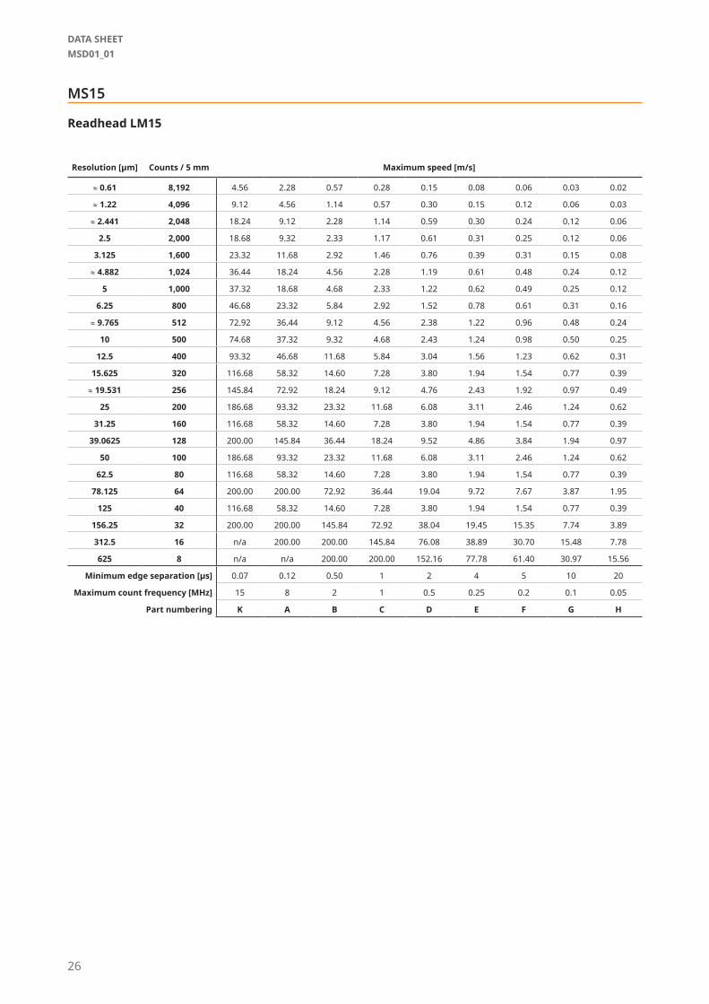
MS15
Readhead LM15
Resolution [µm] Counts / 5 mm Maximum speed [m/s]
≈ 0.61 8,192 4.56 2.28 0.57 0.28 0.15 0.08 0.06 0.03 0.02
≈ 1.22 4,096 9.12 4.56 1.14 0.57 0.30 0.15 0.12 0.06 0.03
≈ 2.441 2,048 18.24 9.12 2.28 1.14 0.59 0.30 0.24 0.12 0.06
2.5 2,000 18.68 9.32 2.33 1.17 0.61 0.31 0.25 0.12 0.06
3.125 1,600 23.32 11.68 2.92 1.46 0.76 0.39 0.31 0.15 0.08
≈ 4.882 1,024 36.44 18.24 4.56 2.28 1.19 0.61 0.48 0.24 0.12
5 1,000 37.32 18.68 4.68 2.33 1.22 0.62 0.49 0.25 0.12
6.25 800 46.68 23.32 5.84 2.92 1.52 0.78 0.61 0.31 0.16
≈ 9.765 512 72.92 36.44 9.12 4.56 2.38 1.22 0.96 0.48 0.24
10 500 74.68 37.32 9.32 4.68 2.43 1.24 0.98 0.50 0.25
12.5 400 93.32 46.68 11.68 5.84 3.04 1.56 1.23 0.62 0.31
15.625 320 116.68 58.32 14.60 7.28 3.80 1.94 1.54 0.77 0.39
≈ 19.531 256 145.84 72.92 18.24 9.12 4.76 2.43 1.92 0.97 0.49
25 200 186.68 93.32 23.32 11.68 6.08 3.11 2.46 1.24 0.62
31.25 160 116.68 58.32 14.60 7.28 3.80 1.94 1.54 0.77 0.39
39.0625 128 200.00 145.84 36.44 18.24 9.52 4.86 3.84 1.94 0.97
50 100 186.68 93.32 23.32 11.68 6.08 3.11 2.46 1.24 0.62
62.5 80 116.68 58.32 14.60 7.28 3.80 1.94 1.54 0.77 0.39
78.125 64 200.00 200.00 72.92 36.44 19.04 9.72 7.67 3.87 1.95
125 40 116.68 58.32 14.60 7.28 3.80 1.94 1.54 0.77 0.39
156.25 32 200.00 200.00 145.84 72.92 38.04 19.45 15.35 7.74 3.89
312.5 16 n/a 200.00 200.00 145.84 76.08 38.89 30.70 15.48 7.78
625 8 n/a n/a 200.00 200.00 152.16 77.78 61.40 30.97 15.56
Minimum edge separation [μs] 0.07 0.12 0.50 1 2 4 5 10 20
Maximum count frequency [MHz] 15 8 2 1 0.5 0.25 0.2 0.1 0.05
Part numbering K A B C D E F G H
26
DATA SHEETMSD01_01

Part numbering
MS 10 B 1000 B 0032
Scale type05 - 2 mm pole length, 5 mm width07 - 2.032 mm pole length, 5 mm width10 - 2 mm pole length, 10 mm width12 - 2.032 mm pole length, 10 mm width15 - 5 mm pole length, 10 mm width
Reference mark0000 - No reference markxxxx - Reference mark; xxxx equals position of reference mark in cm
(Reference mark position will be within ±1 mm from requested position)Mxxx - Reference mark; xxxx equals position of reference mark in mm
(Reference mark position will be within ±1 mm from requested position)Dxxx - Distance coded reference mark; xxx equals basic increment KxxxxM - Magnetised reference mark; xxxx equals position of magnetised reference mark in cm
(Available only for MS10. Reference mark position will be within ±1 mm from requested position)
MxxxM - Magnetised reference mark in mm; xxx equals position of magnetised reference mark in mm(Available only for MS10. Reference mark position will be within ±1 mm from requested position)
Pxxx - Multiple reference marks in mm; xxx equals distance between magnetised reference marks in mm, factory predefined to 50 mm, 100mm and 200 mm.(each reference mark position will be within ±1 mm from requested position)
Not all part number combinations are valid. Please refer to the table of available combinations on the next page.
Accuracy classA - ±20 µm/mB - ±40 µm/m
Scale lengthxxxx - xxxx equals scale length in cm
OptionsA - VHB back adhesive tape (standard)B - VHB back adhesive tape; with cover foil *C - VHB back adhesive tape; ends prepared for end clampingG - No VHB back adhesive tape; sides prepared for insertion into track sectionH - No VHB back adhesive tape, sides prepared for insertion into track section; with cover foil *I - No back adhesive tapeN - No back adhesive tape; with cover foil *P - No back adhesive tape; ends prepared for end clamping **
See next page for scale length defining.
Cover foil part numbering
C - ±100 µm/mD - ±10 µm/m
Mxxx - xxx equals scale length in mm
Cover foil width05 - 5 mm08 - 8 mm (for track system option only)10 - 10 mm
CF 10 1000
Cover foil lengthxxxx - xxxx equals foil length in cm
* Cover foil is not factory mounted on the scale and must be ordered separately.** It can only be used when the magnetic scale is installed in the groove to prevent lateral sliding.
The groove dimension must correspond to the scale width.
27
®
A associate company

Series Scale type Accuracy class Scale length Options Reference mark
MS
05 A / B / D xxxx / MxxxA / B / C / I / N / P
0000 / xxxx / Mxxx /Dxxx
07 B xxxx / Mxxx 0000 / xxxx / Mxxx
10 A / B / Dxxxx / Mxxx
A / B / C / G / H / I / N / P
0000 / xxxx / Mxxx /Dxxx / xxxxM /
MxxxM
2000 P050 / P100 / P200
12 B xxxx / Mxxx 0000 / xxxx / Mxxx
15 C xxxx / Mxxx 0000 / xxxx / Mxxx /Dxxx
Table of available combinations
How to define scale length
A
B
Measuring length (C)
Scale length (D)
B
Readhead A B C
LM10* 9 mm Min. 10 mm D – 20 mm
LM13* 7 mm Min. 10 mm D – 20 mm
LM15* 9 mm Min. 10 mm D – 20 mm
RLB 1 mm – D – 10 mm
RLC2HD 1 mm – D – 10 mm
RLC2IC 2 mm Min. 8 mm D – 16 mm
RLM 0 Min. 8 mm D – 10 mm
* For magnetic scale with ends prepared for end clamping (options C and P) refer to page 14.
28
DATA SHEETMSD01_01

Magnet viewerMM0001
Stick-on reference markLM10SRM00
End clamp kitLM10ECL00
(2 clamps + 2 fasteners)
Applicator tool for stick-on reference markLM10ARM00
Track section, 1.00 mTRS100A00
(1x fastener M3x10 included)
Track section, 2.00 mTRS200A00
(1x fastener M3x10 included)
Fastener and washerTRC00
Applicator tool for magnetic scale and cover foilLM10ASC00
Applicator tool for magnetic scale and cover foilLM13ASC00
Scale clamp with fasteners, 0.04 mTRE004A00
(2x fastener M3x10 and 1x fastener M2x4 included)
Accessories
29
®
A associate company

A associate company
®
RLS merilna tehnika d.o.o.
Poslovna cona Žeje pri KomendiPod vrbami 2SI-1218 KomendaSlovenia
Head office
Global support
T +386 1 5272100F +386 1 5272129E [email protected]
RLS Merilna tehnika d.o.o. has made considerable effort to ensure the content of this document is correct at the date of publication but makes no warranties or representa-tions regarding the content. RLS Merilna tehnika d.o.o. excludes liability, howsoever arising, for any inaccuracies in this document. © 2020 RLS d.o.o.
This product is not designed or intended for use outside the environmental limitations and operating parameters expressly stated on the product’s datasheet. Products are not designed or intended for use in medical, military, aerospace, automotive or oil & gas applications or any safety-critical applications where a failure of the product could cause severe environmental or property damage, personal injury or death. Any use in such applications must be specifically agreed to by seller in writing, and is subject to such additional terms as the seller may impose in its sole discretion. Use of products in such applications is at buyer’s own risk, and buyer will indemnify and hold harmless seller and its affiliates against any liability, loss, damage or expense arising from such use. Information contained in this datasheet was derived from product testing under controlled laboratory conditions and data reported thereon is subject to the stated tolerances and variations, or if none are stated, then to tolerances and variations consist-ent with usual trade practices and testing methods. The product’s performance outside of laboratory conditions, including when one or more operating parameters is at its maximum range, may not conform to the product’s datasheet. Further, information in the product’s datasheet does not reflect the performance of the product in any appli-cation, end-use or operating environment buyer or its customer may put the product to. Seller and its affiliates make no recommendation, warranty or representation as to the suitability of the product for buyer’s application, use, end-product, process or combination with any other product or as to any results buyer or its customer might obtain in their use of the product. Buyer should use its own knowledge, judgment, expertise and testing in selecting the product for buyer’s application, end-use and/or operating environment, and should not rely on any oral or written statement, representation, or samples made by seller or its affiliates for any purpose. EXCEPT FOR THE WARRANTIES EXPRESSLY SET FORTH IN THE SELLER’S TERMS AND CONDITIONS OF SALE, SELLER MAKES NO WARRANTY EXPRESS OR IMPLIED WITH RESPECT TO THE PRODUCT, INCLUDING ANY WARRANTY OF MERCHANTABILITY OR FITNESS FOR ANY PARTICULAR PURPOSE, WHICH ARE DISCLAIMED AND EXCLUDED. All sales are subject to seller’s exclusive terms and conditions of sale which, where the seller is (a) RLS Merilna tehnika d.o.o., are available at https://www.rls.si/eng/salesterms, (b) Renishaw, Inc., are available at https://www.renishaw.com/legal/en/--42186, or (c) another person, are available on request, and in each case, are incorporated herein by reference, and are the exclusive terms of sale. No other terms and conditions apply. Buyer is not authorized to make any statements or representations that expand upon or extend the environmental limitations and operating parameters of the products, or which imply permitted usage outside of that expressly stated on the datasheet or agreed to in writing by seller.
www.rls.si
Visit our website to contact your nearest sales representative.