MRF & Cosylab on timing system: integration support Joze Dedic...
21
MRF & Cosylab on timing system: integration support Joze Dedic ( [email protected] ) the best people make cosylab … Head of Hardware
-
Upload
bryan-jefferson -
Category
Documents
-
view
219 -
download
1
Transcript of MRF & Cosylab on timing system: integration support Joze Dedic...

MRF & Cosylab on timing system:integration support
Joze Dedic ([email protected])
t h e b e s t p e o p l e m a k e c o s y l a b
… Head of Hardware

Positioning, wrt timing systems
Cosylab provides support on the system-integration level …and (unlike MRF) we are not focused on the timing transmission
layer Jukka/MRF remains essential part
we understand very well how the EVR and EVG work and we know how to add accelerator specific logic
still hard real-time
…but we are also soft providing drivers or application level SW
Cosylab 2010

…to be on the same page about system integration and our role
Cosylab 2010

Let’s talk dimensions
Cosylab 2010
te
rmin
olo
gy
tim
ing
eve
nt, t
ran
smis
sio
n
rate
,
clo
ck, t
ime
, res
olu
tion
, jit
ter,
accu
racy
,
time
-sta
mp
ing
, re
spo
nse
ra
te,
d
ela
y p
ropa
gat
ion
co
mpe
nsa
tion
…
eve
nt,
dat
a a
nd
pa
ylo
ad
del
ay
com
pen
satio
n
stra
tegy
P
TP
(IE
EE
15
88),
eq
ual
fib
er
len
gth
, ...
a
uto
ma
tic d
ela
y co
mpe
nsa
tion
d
ata
dis
trib
utio
n
pro
toco
l an
d p
rio
ritie
s
RT
da
ta b
us
timing domain knowledge
huh?
timing master
GPS
clock (=signal)
output
RF
clock (=signal)
splitter (1 to n)splitter (1 to n)
receiver m
receiver n
splitter (1 to n)
Resolution
Timetime (=data)
Clock
Jitter
100
10011
10010011
Timing event
10010011
10010011
10010011
timeline
Event transmission rate
output
10010011
Response to event
Propagation delay
timeline
timeline
the two outputs should
change at the very same
moment (at mark o), however
they differ due to accuracy
and precision
Accuracy
Precision
time of actual output
Cosylab, Control System Laboratory
Teslova ulica 30
SI-1000 Ljubljana
Slovenia Accuracy (thesaurus: The quality of being near to the true value) is the mean of the time error between
the time under test and a perfect reference time, over an ensemble of measurements.
Precision (thesaurus: The quality of being reproducible in amount or performance) is a measure of the
deviation of the time error between the time under test and a perfect reference time from the mean
time error.Jitter is unwanted variation of a periodic signal's property (e.g. period).
Latency is time delay between the moment something is triggered on the source's end and the moment it is detected on the receiving end..
Signal propagation delay is the time that is required for a signal to travel along the transmission layer. For accelerator timing systems this cannot be
neglected; e.g. it takes ~1s to transmit a pulse over 200m of fiber (speed of signal delivery in optical fiber is ~c/1.5). If required, timing system design
enables compensation of different propagation delays (due to different cable lengths).
Resolution is defined by a minimum discrete step in which a) outputs can be set or b) inputs can be time-stamped. I.e., it is the granularity by which
actions can be made or stimuli perceived.
Cosylab timing team cheat-sheet; for further explanation contact - [email protected]
2009-12-07
inputResolution
00
0?
11
11
Time-stamping
the process of
determining time when
signal changed (with the
perception of local time)
Accuracy
Timing event is a sequence of bits (corresponding to event encoding and, if applicable, also to event
payload), sent over the real-time dedicated timing system network. It originates from master timing generator
and must be decoded in hard real-time by all timing receiver components when received.

Let’s talk dimensions
Cosylab 2010
timing domain knowledge
“har
dwar
e”
dedicated FPGA, must have VHDL
timing-receiver code
special devices, tightly integrated in
timing system
SW
drivers
add IOs for HW
triggers (for dumm
y
devices)
sm
all add-on to basic FPGA FW code
PCB layout; board design is not trivial
anymore, and costly
VM
E, PXI…
target platform
FPGA FW
code not complex
prototype
(Xilinx dev board for <$500)
8b/10b, fiber link
FPGA + SFP

Let’s talk dimensions
Cosylab 2010
timing domain knowledge
“har
dwar
e”
integration know-how
tests, documentation, support, training… (straightforward) implementation slaves; RT part; FPGA,SW part; integrate
with “simple” devices, tightly embed with complex devices
master; RT part; FPGA, SW part configure hardware (access to the
implementation source code, FPGA expert, low-level SW expert…)
virtual accelerators, execution slots, deliver user data
sync with (patient) breathing, linac grid… sync with mains (but… not too fast for
choppers, etc…) machine physics, accelerator/machine
specific requirements

Let’s talk dimensions
Cosylab 2010
“har
dwar
e”
timing domain knowledge
integration know-how
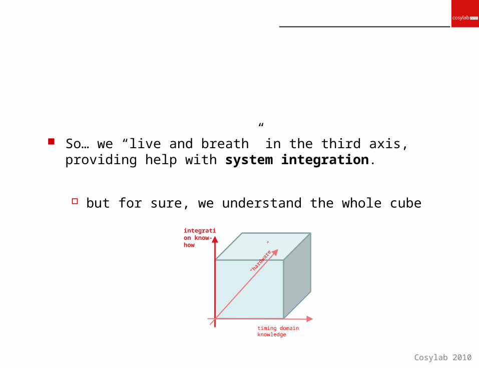
So… we “live and breath” in the third axis, providing help with system integration.
but for sure, we understand the whole cube
Cosylab 2010
“har
dwar
e”
timing domain knowledge
integration know-how

Cosylab 2010
MedAustronMedAustron centre for ion-therapy and researchComplete timing system

MedAustron timing
Cosylab 2010
1x MRF EVG
n-x MRF EVR
REDNET = real-time event and data network
requirement analysis, architecture design development, testing…
FPGA LV driver (complete
development framework)…
MR
F ne
twor
k

MA; EVG++
VAcc (ExecSlots), multiple tables; 256 entries, relative delay all tables synced to internal time grid (VAcc specific offset) command / data / XML real time data distro to receiver clients (all
per ES) asynchronous events priorities automatic heart beat generation
Cosylab 2010
ES 3
ES 2
Global Scheduling
ES 0
ΔtEvent Type
Identifier
Event Table
Commands
Asynchronous Timing Events
Heartbeatevent
generator
214
ES 1
ΔtEvent Type Identifier
Event Table
Commands
Asynchronous Timing Events
33
12
5 8
MRF EVG
VA 4
VA 1
VA 0
ΔtEvent Type Identifier
Event Table
Commands
Asynchronous Timing Events
Seqencer
Internal Interfaces
5 Virtual Accelerators
Seqencer
HeartbeatEvent
generator
Internal Interfaces
PXI crate controller
ReceivercomponentsReceiver
componentsReceiver
components
Internal HW interface (cPCI)
Fast Equipment Interface - FEI (real-time fiber optic link)
Timestamp
Heartbeat offset

Cosylab 2010
MA; Receiver side
digital/optical signals on the MRF EVR outputs distribute events to clients (neighbor PXI cards) trigger clients (neighbor PXI cards) software IRQ (LV Vis) time stamping support distribute reference clock (10 MHz GPS)
MTR PXI
PXI - System Controller
Device specificFECOS
Component
hard drive
RAM
MTRFECOS
Component
PXI backplane
MRF EVR
Internal HW interface (cPCI)
FlexRIOFlexRIO
AuxiliaryInterface
AI1
4 TTL outputs
4 optic outputs
OR
EVR TTL/opticAuxiliary Interface
FlexRIO
PXI Shared Trigger Lines
PXI Shared Trigger Bus
(ETID distribution)
Notifications to MTR FECOS component

MA; EVR++ (flex. outputs)
Cosylab 2010
Event response configuration table*TIMING CONFIG. PTR
(3:0)P/T(1)
CARD(3:0)
STL(1)
STB(1)
IRQ(1)
AI output(3:0)
256 Rows
AI output timing configuration table*W1
(16)Δt1(16)
16 Rows
Δt2(16)
Δt3(16)
Δt4(16)
W2
(16)W3
(16)W4
(16)
Auxiliary Interface response generation
(FPGA Logic)
Default W(16)
Default Δt(16)
Pulse/Toggle
AI Output Number
Delay and Width parameters (per ETID)
AI Output 1
AI Output 2
AI Output 3
AI Output 4
WL1
(16)ΔtL1
(16)
WL2
(16)ΔtL2
(16)
WL3
(16)ΔtL3
(16)
WL4
(16)ΔtL4
(16)
WL5
(16)ΔtL5
(16)
WL6
(16)ΔtL6
(16)
WL7
(16)ΔtL7
(16)
Star Trigger Line response generation
(FPGA Logic)
Shared Trigger Bus response generation
(FPGA Logic)
PXI PCI Interupt generation
(FPGA Logic)
PXI Star Trigger lines (7)
PXI Shared Trigger Bus (8)
PXI PCI Interface
PXI PCI IRQ
8 ETID
Card Number (indicating Star Trigger Line)4
Response gen. on PXI Star Trigger Lines enabled (for received ETID)
Response gen. on PXI Shared Trigger Bus enabled (for received ETID)
Generation of PCI interrupts is enabled (for received ETID)
ETID
ESGPS TS
TS rel. to CS
CID
ETID
8
7
8
4
Star Trigger Line timing configuration table*
Default AI output timing configuration registers*
* All memory tables and registers are accessible to the MTR FECOS component through the PXI PCI interface.
Card Number (indicating Star Trigger Line)4
4 aux outputs
7 start trigger lines
8 backplane trigger bus
PCI IRQ; VIs
delay propagation compensationfully flexible output configurationconcurrent response generation
all events can map to any of the 16 different settings: pulse, delay, width, toggle/pulse (per output, per event)
…but still optimized for resource usage

ORNL SNSSpallation neutron sourceTiming master renovation
Cosylab 2010

SNS
in the period 2008-2010 we cooperated on SNS timing system renovation
old HW (several VME crates) moved to single Virtex 5 LX-50
requirements, architecture, development, testing
did not touch transfer layer, only the master
Cosylab 2010
I2C
16x RF
20MHz
EL
VME
EL_EventTableEL_SoftEventFIFOEL_EventConfigTableEL_SuperCycleTable
RTDL_Table
registers I/F
IRQ handler
generic VME I/F
RTDL
master ref. generator
line frequency measurement
DDS frequency generator
GPIO control
EL_ResetTurnCounter
LineZeroCrossing
EL_to_VM
E_CycleSt
art
trigger IRQ
EL_to_VM
E_5050
clear Autoclea
rMask_reg
& clear RequestR
TDLtransm
it_reg
EL_to_GP
IO_CycleS
tart
rese
t lat
ched
inpu
ts
and
occu
rren
ce m
onito
ring
RTDL_LatchTime @ cycle start
RTDL_LoadData @ end of cycle
RTDL_StartTransmit
GPIO_StartRTDLxmitReq
even
t req
uest
RTDL_Tran
smitDone
IRQ_sources(17:0)
EL_HWeventFIFO
EL out(LVPECL)
RTDL out(LVPECL)
VME P1 VME P2
20MHz
16x RF
20MHz
VMEclk
VMEclk
Crossing clock domainsØ DS - double sample clock cross-
domain registersØ EDS - extend and double sample
clock cross-domain signalsØ UCF must handle this, to avoid
timing errors
Clock
RTDL_TableUpd
ateDone
trigger IRQ
HW_mask_inputs(5:0)
DCMs and buffers
USB I/Fnot supported
Fiber optics module I/F + I2C
not supported
Fiber optics CDR I2Cnot supported
RTC SPInot supported
VMEclk
20MHz
16x RF
SPARE_FRONT_PANEL_OUT
MPS_AR_CARRIER_IN
MPS_LATCH_CARRIER_IN
SPARE_FRONT_PANEL_IN(3:0)
SPARE_P2_OUTPUT(7:0)
SPARE_P2_INPUT(7:0)
VME_FAN_FAIL_LOW_IN
POWER_LINE_REF_IN
GPS_PPS_IN
VME_SYSTEM_FAIL_LOW_IN
GPS_PPS_IN
GPS_TRIGGER_OUT
EL_HWeventFIFO
Turn counter
Collecting, masking & encoding the event
Measuring line phase
Super cycle counter
Overwriting RTDL table
Sending out RTDL frames
Time stamp of the next CycleStart
Reading input and setting
output signals
IRQ control
EL HW eventsEvent masking;
HW-signal sources
EL prim clkCLK_EVENT_LINK_LVDS_0
EL bckp clkCLK_EVENT_LINK_LVDS_2
CLK_LOCAL_HI/LO_IN
CLK_20MHZ16xRF selection
RF measure
System monitor
I2C_SCL_BI,I2C_SDA_BI
SiLabs SI570I2C prog. clock
VMEclk
20x5MHz
20x5MHz
VMEclk
DRP memory mapping
reset
20MHzreset
reset
reset
reset
reset
reset
hold reset after
power up
reset

SNS; Event Link (EL)
Cosylab 2010
sniff for RTDL
start transmit
Ø there is no RTDL start transmit event in RTDL tableØ RTDL transmit is either triggered through host
register or RTDL send timeoutØ once triggered, RTDL start transmit event request is
raised to be stuffed to HW event FIFOØ once it is to be sent out, RTDL start transmit is
requestedØ when finished, RTDL transmit done event also
comes through HW event FIFO
TurnCounter19 bit, init: 0
All events should start at turn tick, the only exception is cycle start, which should start 1/16 earlier. This can be handled in several ways; one might be that after sending out first event (cycle start), 1/16 of the delay is injected into the chain (making this period effectively 17/16 long) and all of the subsequent periods 16/16...
EL_SuperCycleTable1k x 16
EL encoding & sending
SuperCycleCounter:Ø 10 bitØ initialize to 0x000Ø count; 0-599 and restart
EL sourcespriority
event = 0xFF if
nothing there
FSM
RTDL
1 x 32, RSuperCycleCounter_reg
event(7:0)
EL_EventTable16k x 8
EL_HWeventFIFO16 x 8
EL_SoftEventFIFO513 x 8
1
2
3
EL_EventConfigTable512 x 32
1 x 32, RWSoftwareMask_reg
1 x 32, RWAutoclearMask_reg
GPIO control
event configuration(31:0)
supercycle info(11:0)
HW inputs(5:0)
AutoclearMask_reg(5:0)
SoftwareMask_reg(7:0)&
==
CLK_16xRF
EL_ResetTurnCounter
GPS_TRIGGER_OUT
EL out(LVPECL)
CLK distribution
master refgen
1 x 32, R (16xRF resolution)LinePhase_reg
latch @ 0-crossingLineZeroCrossing
turn counter decoderØ cycle start, @0Ø 5050Ø EndOfCycle_reg, def 5150 Ø DelayRTDLsendTimeout_reg, def 500
RTDL send timeout
VME
increment
@ 5050
if(( )
)event_out <= event;
elseelse event_out <= 0x00;
counter value
HW_ma
sk_inpu
ts
EL_to_VME_CycleStart
trigger IRQ
RTDL_LoadData @ end of cycle
RTDL start-transmit logic
1 x 32, RWRequestRTDLtransmit_reg RTD
L_Start
Transm
it
GPIO_StartRTDL
xmitReq
counter value
GPIO control
EL_to_GPIO_CycleStartreset latched inputs and occurrence monitoring
*auto cleared in VME, init as 0
EL_to_VME_5
050
clear AutoclearM
ask_reg & clear
RequestRTD
Ltransmit_reg
*auto cleared in VME
Provide a 10 to 100 us pulse corresponding to cycle start.
RTDL_LatchTime @ cycle start
Ø MPS Auto ResetØ MPS latchØ Front panel spare 3Ø Front panel spare 2Ø Front panel spare 1Ø Front panel spare 0
event configuration(31:0) Ø Host Alive
Ø Beam OnØ Diagnostic FastØ Diagnostic SlowØ Diagnostic DemandØ Spare
BEAM_ON_LED_OUT
0x00 means no event
if turn counter > 0x3FFF
event table reads 0
init as 0
if clocked with 32xRF, reset of the turn counter must be done when LSB is 1 (i.e. not to infer EL data polarity shift with respect to the RF)if clocked with 16xRF, it does not matter (think in the frame of reading 32 bit LUTs per turn, which have to be fully sent out)
CLK distribution
CLK_16xRF
18:4 – whole turns £ 327673:0 – sub-turn counter £ 15
Ø supercycle counter is incremented @5050(request RTDL transmit reg is also cleared)
Ø RTDL data is loaded @ EndOfCycle_reg; 5150~5650Ø RTDL send timeout happens DelayRTDLsendTimeout_reg
time later 200~1000, default 500
signal out @ cycle start
there must be a constant ‘propagation’ delay from the turn counter changeover to the moment appropriate event starts coming out (it’s length is not important as the phase tracking mechanism handles this implicitly)
Another very neat mechanism is to prepare LUTs for all events for the entire RF period (all 32 bits) and just sent that out (parity bit takes care all the phases match and the output stream could consists simply of concatenating appropriate events, no encoding would have to be done this way). 1/16 of the shift would be implemented as all the events except first one to be shifted by 1/16. Event 0 would also be encoded. All events would start with 1 and end with 0!
ODDR, SAME_EDGE
1 x 32, RWDelayRTDLsendTimeout_reg
1 x 32, RWEndOfCycle_reg
CycleStart event jostle must be prohibited; There are at least two ways to achieve that; a) to prohibit loading new events after 16384 (2^14) or b) to have turn-counter to event-out propagation larger or equal than one turn and prohibit loading new events when reset is detected.
implemented in VME, signal passed to EL
(10101010101010101010101010101010)

SNS; catching mains
Cosylab 2010
Fo as function of tuning word T, expressed as offset from T(60Hz)
59.800
59.840
59.880
59.920
59.960
60.000
60.040
60.080
60.120
60.160
60.200
-4,500 -4,000 -3,500 -3,000 -2,500 -2,000 -1,500 -1,000 -500 0 500 1,000 1,500 2,000 2,500 3,000 3,500 4,000 4,500
5x20 MHz
0-crossing@ 5050
0-crossing@ 5050
reset EL counter
reset EL counter
nominally:16,666 ± 500 µs
1/fRF »911-973 ns
0-crossing@ 5050
local 20 MHz counter:Ø 32-bitØ latch @ line 0-crossing
Ø no reset
+
desired output frequency Fo 60 [Hz]adder freqency Fs 100 [MHz]
desired Fo resolution Fores 50 [Hz]
number of bits required N.round 41 [bit]actual Fo resolution Fores.calc 45.5 [Hz]
ideal output-period step DTo 12.6 [ns]Fo jitter 1/Fs 10 [ns]
1 x 32, RLinePeriod_reg(50 ns resolution)
1 x 32, RWDDS_tuning_word_reg
preset with 60 Hz value
POWER_LINE_REF_IN
EL_ResetTurnCounter
LineZeroCrossing
overflow
detection
ELCLK
distributionCLK_20M
Line frequency counter and the line frequency generator must be derived from the same clock source.
Line frequency counter and the line frequency generator must be derived from the same clock source.
0.033333333 911.2 973.4
Fdesired Tuning word T-T(60) Factual16 x turncounter
16 x turncounter
59.80 1,315,016 -4398 59.80000 293,633 274,870
59.83 1,315,749 -3665 59.83334 293,470 274,717
59.87 1,316,482 -2932 59.86667 293,306 274,564
59.90 1,317,215 -2199 59.90000 293,143 274,411
59.93 1,317,948 -1466 59.93334 292,980 274,259
59.97 1,318,681 -733 59.96667 292,817 274,106
60.00 1,319,414 0 60.00000 292,654 273,954
60.03 1,320,147 733 60.03334 292,492 273,802
60.07 1,320,880 1466 60.06667 292,330 273,650
60.10 1,321,613 2199 60.10000 292,167 273,498
60.13 1,322,346 2932 60.13333 292,005 273,346
60.17 1,323,079 3665 60.16667 291,844 273,195
60.20 1,323,812 4398 60.20000 291,682 273,044
0b1010000 & word(13:0)
Tuning word Factual0b101000000000000000000 1,310,720 59.60464
0b101000011111111111111 1,327,103 60.34966
LINE_STS_LEDecho POWER_LINE_REF / stretch 50%
CLK_20Mx5
phase measurement register is in EL module
Period MeasureØ Mains Frequency Ø TC Reset Frequency
(DDS)1 x 32, RLineZeroCrossingFreq
1 x 32, RTurnCounterResetFreq MainsTracking
complete timing operation breathes with mains and waits for choppers (rotation inertia)
synthesizing ~60 Hz (50 mHz) to follow mains + PID regulator

and others…We can help you time your machine.
Cosylab 2010
And we can save you time.

Cosylab 2010
Our role
MRF support with customization FPGA or drivers customizing timing system to the specific machine
specially for new machines and upgrades: requirements gathering help define conceptual solution
granularity windows, event/payload/data scheme, integrating target devices, concept of virtual accelerators, priorities
take over architectural design; FPGA, drivers… and even complete timing SW support framework
implementation, testing

MPS on MRF
use MRF for robust real-time data distro nodes time sync (post mortem…)
we were showing a demo @ PCaPAC 2010
Cosylab 2010
Local Response
Global Response
MPS Optical Communication
Control System (Ethernet)
CPUMPS Node
I/OMPS
Splitter
CPUMPS
Master
CPUMPS Node
CPUMPS Node
I/O I/O
Active Devices
MPS Inputs
Diagnostic Devices
I/O
generic part; capture inputs, respond locally/globally (data distro)
IOs can should be modular
logic (in/out relation) should be configurable

Cosylab 2010…time out.


![(trom 1st 1 £7' DOY GOPE GRAS GRAZ HERS JOZE KELY … · NYAI averaged Z TD (El-JR-SIO) difference [mm] 7.445 5.644 5.847 3.379 EPN ZTD combined product SIO gb bal so lubon for JOZE](https://static.fdocuments.us/doc/165x107/5d208ae188c993ec448d450f/trom-1st-1-7-doy-gope-gras-graz-hers-joze-kely-nyai-averaged-z-td-el-jr-sio.jpg)