MRF-250 INSTALLATION MANUAL - fccid.io · Page 1 MRF-250 BASE STATION Introduction The combination...
16
Multi-Room “No-Pointing” RF Control of Audio/Video Components MRF-250 INSTALLATION MANUAL
Transcript of MRF-250 INSTALLATION MANUAL - fccid.io · Page 1 MRF-250 BASE STATION Introduction The combination...
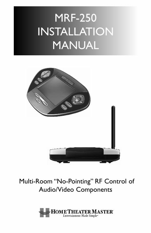
Multi-Room “No-Pointing” RF Control ofAudio/Video Components
MRF-250INSTALLATION
MANUAL

MRF-250 Installation Manual © 2004 Universal Remote Control, Inc.
The information in this manual is copyright protected. No part of this manual may be copiedor reproduced in any form without prior written consent from Universal Remote Control, Inc.
UNIVERSAL REMOTE CONTROL, INC. SHALL NOT BE LIABLE FOR OPERATIONAL,TECHNI-CAL OR EDITORIAL ERRORS/OMISSIONS MADE IN THIS MANUAL.
The information in this manual may be subject to change without prior notice.
Home Theater Master is a registered trademark of Universal Remote Control, Inc.Entertainment Made Simple is a trademark of Universal Remote Control, Inc.
All other brand or product names are trademarks or registered trademarks of their respectivecompanies or organizations.
500 Mamaroneck Avenue, Harrison, NY 10528 Phone: (914) 835-4484 Fax: (914) 835-4532

TTAABBLLEE OOFF CCOONNTTEENNTTSS
Introduction 1
Features and Benefits 2
Parts Guide 2
Front Panel 3
Mounting Plate 3
Power LED 3
Status LED 3
Front Blaster 3
Rear Panel 4
Flashers 4
Power Supply 4
Bottom Panel 4
Receiver ID# 4
A Standard MRF-250 System 5
Standard Installation — Step by Step 5
Front Blaster Overload 7
Disabling the Front Blaster - Step by Step 7
Controlling An Array of Identical TV’s 8
Identical Components - Step by Step 8
Programming For Multiple Equipment Locations 11
Frequently Asked Questions 12
Specifications 12

PPaaggee 11
MMRRFF--225500 BBAASSEE SSTTAATTIIOONN
Introduction
The combination of the MX-3000 with it’s companion MRF-250 base stationwill enable you to place your audio/video components out of sight behindclosed doors and/or in another room of your house. The MX-3000 sendsradio signals to the MRF-250 throughout your house (50-100’ away, indoors oroutdoors). The MRF-250 converts your commands to the infrared signals thatcontrol your A/V components.
3. Self-adhesive “Flashers” affix to theInfrared sensors on the front panelsof your components. The Flashersrelay commands to components outof sight of the MRF-250’s FrontBlaster. The flashers plug in to theMRF-250’s rear flasher line outputsvia their 10 foot cables.
2.The MRF-250’s built-in Front Blaster sends commands tocomponents in the same cabinet space as the MRF-250.
1.The MX-30000 remote con-trol sends radio waves inevery direction, so you don’thave to point the remote any-more!

PPaaggee 22
MMRRFF--225500 BBAASSEE SSTTAATTIIOONN
Features and BenefitsNNoo MMoorree PPooiinnttiinngg -- RRaaddiioo WWaavveess PPeenneettrraattee WWaallllss,, DDoooorrss aanndd FFlloooorrssThe MRF-250 receives the RF signals of the MX-3000 remote control fromany direction. You no longer need to point the remote control at any of yourA/V components. You can also place the components distracting blinking lightsand displays behind closed doors and/or in another room!
RReelliiaabbllee CCoonnttrrooll TThhrroouugghhoouutt YYoouurr HHoouusseeThe MRF-250 receives RF signals from your MX-3000 from within a radius of50 to 100 feet enabling you to control out of sight audio/video componentsbehind walls and closed doors. Range depends on the structure of your homeand the amount of interference generated by computers, microprocessors andother devices within and nearby your home.
UUpp TToo SSiixxtteeeenn EEqquuiippmmeenntt LLooccaattiioonnss CCoonnttrroolllleedd FFrroomm AAnnyy MMXX--33000000Each MX-3000 can be programmed to operate equipment placed throughoutthe house, by installing an MRF-250 base station at each location. Each MRF-250 is assigned one of 16 unique ID#’s. In operation it’s simple: when youselect a device located in the Den, the MX-3000 only talks to the MRF-250 inthe Den. When you select a device located in the Family Room, the MX-3000only talks to it!
NNoo PPooiinnttiinngg RReemmoottee CCoonnttrroollss IInn EEvveerryy RRoooommYou can opt to control a multi-room or multi-zone system via RF remote con-trol by placing an MX-3000 in each room of your home.
CCoonnttrrooll AA MMeeddiiaa RRoooomm AArrrraayy ooff IIddeennttiiccaall TTVV’’ssThe MRF-250’s unique assignable IR flashers enable your installation to controlup to six identical TV’s. The intelligent routing of the MRF-250 will send yourcommands only to the TV you select on your MX-3000. The other identicalTV’s will not receive commands. Of course, if your system utilizes identicalsatellite receivers, cable boxes, VCR’s or disc changers you can utilize IR rout-ing just as easily for them. If you have more than six identical components, upto 16 additional MRF-250’s can be installed to control them (thus allowing upto 96 identical components in one house).
Parts GuideThe MRF-250 RF Base Station includes:
1 - MRF-250 Receiver with integrated antenna1 - Mounting Plate for wall mounting the MRF-2504 - Screws for wall mounting the mounting plate1 - 9V-300mA Power Supply6 - Flashers with 10 foot plug in cables.

PPaaggee 33
MMRRFF--225500 BBAASSEE SSTTAATTIIOONN
The MRF-250’s slots enable theMounting Plate’s matching guidesto slide and “snap” into place formounting on the wall.
Using the four enclosedscrews, you can choose to fixthe mounting plate to a wall orthe back of your componentcabinet.
Front Blaster sends Infrared com-mands to all A/V components inthe same cabinet space.
The MRF-250 Mounting Plate
MRF-250 Details
Red POWER LED lights when theMRF-250’s power supply is pluggedinto an active AC outlet.
Red STATUS LED lights when theMRF-250 receives an RF signalfrom the MX-3000.

PPaaggee 44
MMRRFF--225500 BBAASSEE SSTTAATTIIOONN
Six Plug-In Flashers are suppliedwith 10 foot cables and six extraself-adhesive pads (in case a flash-er has to be repositioned).
Bottom panel Dial sets the Receiver ID# whenmore than one MRF-250 receiver is used.
Included 9V power supplyplugs into the MRF-250’spower connector.
Integrated Antennaswings in any directionto optimize RF recep-tion and range.
Six Rear Flasher Line Output Jacksconnect flashers for control of A/Vcomponents out of sight of the MRF-250’s Front Blaster.

PPaaggee 55
MMRRFF--225500 BBAASSEE SSTTAATTIIOONN
A Standard MRF-250 System
A standard system utilizes no identical components and only one equipmentlocation. However, you can add any number of MX-3000 remote controls toyour home! MX-3000’s are available as an accessory purchase without anMRF-250 for standard system installations that already have an MRF-250.
You can add any number of MRF-250 base stations in a standard system aswell. If you need more than six flasher outputs you may add additional MRF-250 receivers as needed by ordering an accessory MRF-250 base station.
Do not change the factory default settings in RF Control section of MX-3000Editor when you download to your MX-3000’s. You do not need to utilizeMX3000 Editor’s Program Step 9 (RF Control), since the factory settings willwork fine!
Standard Installation — Step by Step
SStteepp 11 -- PPrrooggrraamm aanndd DDoowwnnllooaadd ttoo tthhee MMXX--33000000 Connect your MX-3000 to your PC and program the IR commands and macrosas you like. Since your MX-3000 sends both IR and RF, you can test your pro-gramming as you go by pointing the MX-3000 at the components and using MX-3000 Editor’s TEST and Macro Play features if you place your laptop PC in thesame room as the components (with the cabinet doors open and in line of sight).
For a detailed explanation of how to program, use the downloadableProgramming Manual or the animated Tutorial. Both are available as free down-loads from the www.hometheatermaster.com website.
IImmppoorrttaanntt NNoottee:: DDoo NNOOTT ppoowweerr uupp tthhee MMRRFF--225500 aatt tthhiiss ppooiinntt.. YYoouu nneeeedd ttootteesstt yyoouurr IIRR ccoommmmaannddss aanndd MMaaccrrooss lliinnee ooff ssiigghhtt vviiaa IIRR oonnllyy aatt tthhiiss ppooiinntt!!
Once you have completed and downloaded your programming to the MX-3000 remote control, you are ready to test RF operation via the Front Blasterand (if necessary) the self-adhesive flashers that connect to the MRF-250’sflasher line outputs.
SStteepp 22 -- PPllaaccee tthhee MMRRFF--225500The MRF-250 should be placed so that the Front Blaster will control as manyof the system’s A/V components as possible. If you are connecting the out-board flashers to the rear Flasher outputs only, the MRF-250 may be con-cealed and mounted to the rear wall or back of the system cabinet.The

PPaaggee 66
MMRRFF--225500 BBAASSEE SSTTAATTIIOONN
mounting plate slides apart from the receiver, screws to the wall or cabinetwith the enclosed screws, then the receiver is slid back into place.
SStteepp 33 -- CCoonnnneecctt tthhee PPoowweerr SSuuppppllyy aanndd IInnsseerrtt tthhee BBaatttteerriieessConnect the 9V power supply to an active UNSWITCHED AC outlet. The MRF-250 must always be powered up to operate.The red POWER LED should light.Insert the batteries in the MX-3000 remote control.
SStteepp 44 -- TTeesstt tthhee MMXX--33000000 Observe the MRF-250’s STATUS LED blinking while you press and hold a pro-grammed button (one with an actual command).This tells you that the MRF-250 is receiving the RF commands of the MX-3000. However, if the LED con-tinues to flicker after you release the button, you are receiving RF Interferenceand you must move the MRF-250 to another location.
SStteepp 55 -- OOrriieenntt tthhee AAnntteennnnaa ffoorr OOppttiimmuumm RRaannggeeIf you need to extend the range of the remote, try adjusting the angle of theMRF-250 receiving antenna via it’s pivoting ball mount.
SStteepp 66 -- TTeesstt OOppeerraattiioonn WWiitthhoouutt FFllaasshheerrssWith the MX-3000’s IR output blocked by a jacket or pillow, test the control ofyour components using just the Front Blaster. In most cabinets, the MRF-250’sFront Blaster will control any A/V components in the same cabinet space byreflections from the cabinet walls and doors. Make sure that the componentsoperate with the cabinet doors closed or open. If a component is placed too faraway from the front blaster, you will need to utilize the included Flashers pluggedinto the MRF-250’s rear Flasher Line Output jacks.
If you have problems with components that are close to the Front Blaster, seethe next page and the section on Front Blaster Overload.
SStteepp 77 -- CCoonnnneecctt FFllaasshheerrss ttoo OOuutt ooff SSiigghhtt AA//VV CCoommppoonneennttss IImmppoorrttaanntt NNoottee:: TTeesstt tthhee ooppeerraattiioonn BBEEFFOORREE ssttiicckkiinngg tthhee ffllaasshheerr iinn ppllaaccee..
Use a flashlight to identify the correct location of the component’s IR sensor,then try a few commands while moving the flasher around the face plate ofthe component. The most reliable operation typically occurs a half inch or soaway from the IR sensor.
Once you have found the spot that gives the most reliable operation, peel offthe protective backing of the self-adhesive tape on the included Flashers andstick them in place.
IImmppoorrttaanntt NNoottee:: AAllwwaayyss rreeppllaaccee tthhee sseellff--aaddhheessiivvee ttaabbss iiff yyoouu hhaavvee ttoo rreeppoossii--ttiioonn aa ffllaasshheerr.. SSiixx eexxttrraa sseellff--aaddhheessiivvee ttaabbss aarree ssuupppplliieedd ffoorr tthhiiss ppuurrppoossee..

PPaaggee 77
MMRRFF--225500 BBAASSEE SSTTAATTIIOONN
Front Blaster Overload
A few models of audio/video components can be OVERLOADED by the FrontBlaster. If you are having intermittent or inconsistent results with a particularcomponent, try repositioning the MRF-250 and facing the Front Blaster in adifferent direction. If this improves the situation but is impractical, it may benecessary to utilize the self-adhesive flashers only and follow the steps belowto Disable the Front Blaster. This will limit the number of components yourMRF-250 can control to six. If you have more than six components you canpurchase an additional MRF-250 (available as an accessory alone from yourHome Theater Master dealer). Do not change the receiver ID# (use the sameID # as the first unit) then follow the steps on the following pages:
Disabling the Front Blaster - Step by Step
Plug the MX-3000 back into the PC. Open your saved configuration and followthese steps to turn off the front blaster:
SStteepp 11 -- OOppeenn tthhee RRFF SSeettuupp WWiinnddoowwThe RF Setup window opens after selecting RFControl from the Program Menu.
SStteepp 22 -- RReevveeaall tthhee RReecceeiivveerr sseettttiinnggssExtend the RF Setup window by click-ing on the Receivers button.
SStteepp 33 -- TTuurrnn ooffff tthhee FFrroonntt BBllaasstteerrClick on the cell in the IR Blastercolumn.A list box will appear. SelectOFF from the list.
SStteepp 44 -- SSaavvee aanndd DDoowwnnllooaadd ttoo tthhee MMXX--33000000SAVE your changes using File|Save and DOWNLOAD to the MX-3000.
NNeexxtt,, cclliicckk oonn OOKK ttoo aappppllyy yyoouurrcchhaannggee..

Controlling An Array of Identical TV’s (or VCR’s, Receivers, CD players etc.)
There are several considerations to take into account when you are installingan MRF-250 to control an array of identical components:
1. You cannot use the Front Blaster to control identical components. Youmust use Flashers instead. You can still use the Front Blaster in a cabinetthat is out of sight of the identical components to control the rest of yoursystem.
2. Each identical component must receive IR commands ONLY from a dedicat-ed Flasher affixed to it’s front panel. The IR output of the MX-3000 shouldbe disabled for each identical component. It can still be utilized for the restof your system!
3. You must note the NUMBER of the Flasher Output you have utilized forEACH of the identical components.
NOTE: If the identical components are near each other the Flashers and theactual sensor window of the component should be blocked with blackelectrical tape (sometimes more than one layer is needed).
Identical Components - Step by Step SStteepp 11 -- CCrreeaattee aa DDeevviiccee ffoorr EEaacchh TTVV iinn MMXX--33000000 EEddiittoorrThe MX-3000 can control up to 20 devices. You must create one device foreach of your identical TV’s.
In this example, six iden-tical TV’s are utilized in aMedia Room array.
The programmer hascreated devices for all ofthe equipment in thecabinet on Main Page 1.On Main Page 2, he/shehas created a device foreach of the TV’s.
SStteepp 22 -- PPrrooggrraamm OOnnee DDeevviiccee WWiitthh IIRR ccoommmmaannddss..Using either the IR Database or Learning, program one of the identical devicesto operate one of TV’s (leave the others powered off right now).Test all com-mands and Save your work.
PPaaggee 88
MMRRFF--225500 BBAASSEE SSTTAATTIIOONN

PPaaggee 99
MMRRFF--225500 BBAASSEE SSTTAATTIIOONN
SStteepp 33 -- CCooppyy TThhee PPrrooggrraammmmeedd DDeevviicceeIn tree view, right click on the device you programmed.From the context menu that appears, select COPY.
SStteepp 44 -- PPaassttee TThhee PPrrooggrraammmmeedd DDeevviicceeIn tree view, right click on the first device that is NOTPROGRAMMED. From the context menu that appears,select PASTE.
Repeat this PASTE on all of the other identical device. Saveyour work.
SStteepp 55 -- OOppeenn tthhee RRFF SSeettuupp WWiinnddoowwThe RF Setup window opens after selecting RFControl from the Program Menu.
The RF Setup window is composed of a “spread sheet” of options for EACHof your devices. By looking at the Signal column, you can see that the factorydefault programming sets all of the devices to send both IR and RF commands.If you look at the column for Flashers, you can see that the default sends IRcommands for all devices to ALL of the flashers. Both options must bechanged for identical components.Additionally, if you are not using it, you maywish to disable the Front Blaster (see page 7 for directions).
SStteepp 66 -- AAddjjuusstt tthhee SSiiggnnaall FFoorr EEaacchh ooff tthhee IIddeennttiiccaall DDeevviicceessThe RF Setup window enables you to adjust the Signal output by the MX-3000for each device individually, by clicking on the intersection of a row and a col-umn and then selecting RRFF from the three options shown in the pull down listbox .
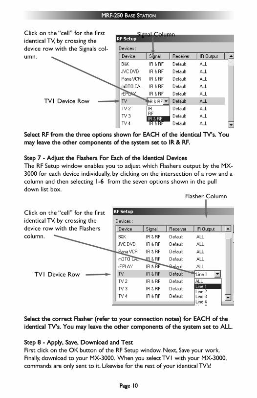
Click on the “cell” for the firstidentical TV, by crossing thedevice row with the Signals col-umn.
SSeelleecctt RRFF ffrroomm tthhee tthhrreeee ooppttiioonnss sshhoowwnn ffoorr EEAACCHH ooff tthhee iiddeennttiiccaall TTVV’’ss.. YYoouummaayy lleeaavvee tthhee ootthheerr ccoommppoonneennttss ooff tthhee ssyysstteemm sseett ttoo IIRR && RRFF..
SStteepp 77 -- AAddjjuusstt tthhee FFllaasshheerrss FFoorr EEaacchh ooff tthhee IIddeennttiiccaall DDeevviicceessThe RF Setup window enables you to adjust which Flashers output by the MX-3000 for each device individually, by clicking on the intersection of a row and acolumn and then selecting 11--66 from the seven options shown in the pulldown list box.
Click on the “cell” for the firstidentical TV, by crossing thedevice row with the Flasherscolumn.
SSeelleecctt tthhee ccoorrrreecctt FFllaasshheerr ((rreeffeerr ttoo yyoouurr ccoonnnneeccttiioonn nnootteess)) ffoorr EEAACCHH ooff tthheeiiddeennttiiccaall TTVV’’ss.. YYoouu mmaayy lleeaavvee tthhee ootthheerr ccoommppoonneennttss ooff tthhee ssyysstteemm sseett ttoo AALLLL..
SStteepp 88 -- AAppppllyy,, SSaavvee,, DDoowwnnllooaadd aanndd TTeessttFirst click on the OK button of the RF Setup window. Next, Save your work.Finally, download to your MX-3000. When you select TV1 with your MX-3000,commands are only sent to it. Likewise for the rest of your identical TV’s!
PPaaggee 1100
MMRRFF--225500 BBAASSEE SSTTAATTIIOONN
Signal Column
TV1 Device Row
Flasher Column
TV1 Device Row

PPaaggee 1111
MMRRFF--225500 BBAASSEE SSTTAATTIIOONN
Programming For Multiple Equipment Locations
You can operate up to 16 different equipment locations, each with an MRF-250 assigned a unique Receiver ID#. You program each of your MX-3000’s totalk to the equipment locations you want by assigning each of your devices toa receiver. First, you must add and name your receivers for the locations theyare placed in:
SStteepp 11 -- OOppeenn tthhee RRFF SSeettuupp WWiinnddoowwThe RF Setup window opens after selecting RF Control from the ProgramMenu.
SStteepp 22 -- RReevveeaall tthhee RReecceeiivveerr sseettttiinnggssExtend the RF Setup window by clicking on theReceivers button of the RF setup window.
SStteepp 33 -- AAdddd,, NNaammee aanndd AAssssiiggnn RReecceeiivveerr IIDD##Using the controls at the bottom extended portion of the RF Control win-dow, add new receivers and rename them for the
SStteepp 44 -- SSaavvee aanndd DDoowwnnllooaadd ttoo yyoouurr MMXX--33000000..
You may rename theDefault receiver tosomething moredescriptive by clickingon the Rename button.
Add new receiversby clicking on theAdd button.
Delete receivers byselecting them firstby clicking on theirName, then clickingthe Delete button.
Assign the correct ReceiverID# for each LOCATION byclicking on the desired CELLand selecting the ID# youwant from the pull down list.Each LOCATION should havea unique ID#. It is ok toinstall multiple MRF-250’s inone location.

PPaaggee 1122
MMRRFF--225500 BBAASSEE SSTTAATTIIOONN
Frequently Asked QuestionsCCaann II uussee ffllaasshheerr//eemmiitttteerrss tthhaatt II hhaavvee aallrreeaaddyy iinnssttaalllleedd iinn tthhee ssyysstteemm ttoo ccoonn--nneecctt ttoo tthhee MMRRFF--225500??Yes, the flashers are compatible, however flashers from other companies are equippedwith a mini plug that is too large to fit the MRF-250’s flasher jacks. Use Radio Shackpart # 274-327 to convert 3.5mm plug Flasher/Emitters to the MRF-250.
II hhaavvee aa rrooww ooff iiddeennttiiccaall TTVV’’ss.. II’’vvee ccoorrrreeccttllyy sseett tthhee ffllaasshheerr oouuttppuuttss uussiinngg MMXX--33000000 EEddiittoorr,, yyeett wwhheenn II sseenndd aa ccoommmmaanndd ttoo oonnee ooff tthheemm,, tthhee TTVV nneexxtt ttoo tthheesseelleecctteedd TTVV aallssoo rreessppoonnddss.. HHooww ddoo II ssttoopp tthhiiss??Use an opaque material like electrical tape to cover the flasher and the front panel sen-sor of each of the TV’s. Sometimes several layers are necessary.
HHooww ccaann II iinnccrreeaassee tthhee rraannggee ooff tthhee MMXX--33000000??Often, you can increase range by repositioning the MRF-250 and/or by re-orienting theantenna. Try to avoid placing the MRF-250 directly adjacent to satellitereceivers, personal computers or any other component using high speedmicroprocessors if possible.
WarrantyThe MRF-250 is covered against any manufacturers defects or workmanshipfor a period of one year from the date of purchase if purchased from anauthorized Home Theater Master dealer. Units purchased from online auctionsites or other unauthorized resellers have no warranty.This warranty does notcover the following items:-Damage from misuse, neglect, or acts of nature.-Products that have been modified or incorporated into other products.-Products purchased more than 12 months ago.-Units purchased from unauthorized dealers or companies.
SpecificationsMMRRFF--225500Power Supply: 9V 300mAIR Flasher Line Outputs: 2.5mm Mono Mini Jack RF Frequency: 418MHzSize: 5 1/8” x 3.5” x 1.25” (4.5” antenna up)

500 Mamaroneck Avenue, Harrison, NY 10528 Phone: (914) 835-4484 Fax: (914) 835-4532