
MRAD Manual
45
MRAD (Multi-Role Adaptive Design) Operator’s Manual PO Box 1077 Murfreesboro, T N 37133 USA / 615.8962938 / 615.896.7313 FAX / [email protected] 03-23-11 P# 12925
-
Upload
blazerman3 -
Category
Documents
-
view
228 -
download
0
Transcript of MRAD Manual

8/3/2019 MRAD Manual
http://slidepdf.com/reader/full/mrad-manual 1/45
MRAD(Multi-Role Adaptive Design)
Operator’s Manual
PO Box 1077 Murfreesboro, TN 37133 USA / 615.8962938 / 615.896.7313 FAX / [email protected]
03-23-11 P# 12925

8/3/2019 MRAD Manual
http://slidepdf.com/reader/full/mrad-manual 2/45
1
Use of this manual
Before you handle the MRAD rifle, read this manual in its entirety. It is
important that you understand the principles of safe gun handling in general
and the unique features of this rifle. This manual is not a substitute for
training from a qualified instructor. Important safety topics are discussed in
this chapter and throughout this manual. This manual should remain with
the rifle and it should be transferred with the rifle to subsequent owners.
Additional manuals can be ordered from Barrett Firearms Manufacturing or
can be downloaded from the company website, www.barrett.net. This manual
covers the MRAD only. Technical specifications are subject to change without
notice.
SAFETY GUIDELINES
Ammunition
Barrett does not condone the use of handloaded, remanufactured, or surplus
ammunition. The use of clean, dry, properly stored, and correct caliber
ammunition will preserve your warranty.
Safety distance
Bullets fired from this rifle may travel as far as 4 miles. Make certain that you
have an adequate backstop.
Hearing protection
Hearing loss is permanent. Hearing loss from gunfire is cumulative, but the
noise from even one shot may cause permanent loss. Wear both ear plugs
and ear muffs. It is also your responsibility to protect the hearing of those
around you. The muzzle brake is integral to the design of your rifle and works
to divert a large portion of a shot’s blast to the side of the muzzle. Your rifle
must not be fired without it. People and objects should not be in the vicinity
of the muzzle brake because its blast consists of high pressure and high
temperature gas. All spectators should use double hearing protection. Thesafest place for a spectator is directly behind the shooter.
WARNING
Failure to follow safety guidelines may cause injury or death.

8/3/2019 MRAD Manual
http://slidepdf.com/reader/full/mrad-manual 3/45
2
Eye protection
Eye protection should be worn when shooting and maintaining your rifle. It is
normal for firing to generate airborne dust and debris. Protect your eyes from
solvents and uncaptured parts under spring pressure while performing
maintenance on your rifle.
Assume every gun is loaded
Always treat every gun as if it were loaded. Look and feel for an empty
chamber. Do not trust your memory and do not take anyone else’s word for it.
Do not trust the extractor to provide an empty chamber.
Beware of barrel obstructions
Ensure the barrel’s bore is free of obstructions before you fire your rifle. Eventhe smallest obstruction such as a stuck patch or even grease will cause
dangerously increased pressures that can rupture the barrel.
Muzzle control
Always keep the muzzle pointed in a safe direction. Never allow your muzzle
to point at anything that you do not intend to shoot.
Keep your finger off the trigger
Keep your finger off the trigger and out of the trigger guard until your sights
are aligned on your target and you intend to fire.
Keep your safety on
Keep your safety on until your sights are aligned on your target and you
intend to fire.
Identify your target and backstop
Before you pull the trigger, make certain of your target and what is in front of,
around and beyond it. The rifle should never be fired at surfaces where
bullets are likely to glance off in unpredictable directions.
Failure to fire
If your rifle fails to fire when you pull the trigger, do not lift the bolt handle to
open the action. Keep the rifle pointed toward a safe area and wait 2
8/3/2019 MRAD Manual
http://slidepdf.com/reader/full/mrad-manual 4/45
3
minutes. If a hangfire (slow ignition) has occurred, the round will probably
fire within two minutes. If the round does not fire, remove and inspect the
cartridge. If the primer is indented properly, discard the cartridge in a safe
manner. If the primer is lightly dented, refer to the troubleshooting chart in
this manual.
Maintain your rifle properly
Performing proper maintenance, as outlined in this manual, ensures that your
rifle will be safe to shoot and will perform to design specification for many
years. Alterations, modifications or adjustments may damage your rifle,
make it unsafe to fire and will void warranty claims.
Store your rifle safelyEven though your rifle represents a significant financial investment, the
greatest value in keeping it secured is preventing it from falling into the
hands of a child, a careless adult, or a thief. It is your responsibility to take
every reasonable precaution to secure your rifle.
Alcohol, medications and drugs
Do not handle or operate your rifle under the influence of alcohol, medicationor drugs.
SUMMARY OF WARNINGS AND CAUTIONS
WARNINGS Summary
• Do not attempt to force a cartridge into the chamber by forcing the boltclosed. If the bolt will not close easily, remove the cartridge and examine
it for damage or defects. Check the chamber for obstructions. (Page 12) • The shooter must be positioned directly behind the rifle with the recoil
pad held firmly against the shoulder. Firing the rifle in any other position
could result in injury by contact with the rifle or rifle scope. (Page 12)
• Unload and clear the rifle before disassembly.
• Ensure no live ammunition is present during disassembly or assembly.
(Page 15)
• Do not remove the coin or other object from the cocking piece while thefiring pin assembly is removed from the bolt tube complete. The firing pin

8/3/2019 MRAD Manual
http://slidepdf.com/reader/full/mrad-manual 5/45
4
spring is under heavy load. Serious injury can occur if the assembly pin is
removed. (Page 25)
• Adjusting the trigger weight too low may cause an accidental discharge.
(Page 31)
• Physically check the chamber and make sure the rifle is not loaded. (Page
35)
• Unload and clear the rifle before cleaning. (Page 36)
CAUTIONS Summary
• The bolt handle must be in the up position before the receivers can be
unlatched. (Page 14)
• Do not force the bolt into place. (Page 23)
• Do not insert cleaning rods through the muzzle. The barrel crown could
be damaged which would severely degrade the accuracy of the rifle. (Page
36)
• To protect the rifle from corrosion, the rifle and the interior of the carrying
case should be moisture free before the rifle is placed in the carrying case
for storage. (Page 36)
WARRANTY AND SERVICEBarrett Firearms Manufacturing Inc. (BFMI), warrants that this firearm was
manufactured free of defects in materials and workmanship. For one year
from the date of purchase by the original owner, BFMI agrees to correct any
defect in this firearm for the original purchaser by repair or replacement with
the same or comparable model.
BFMI will not be responsible for injury, death, or damage to property resulting
from either intentional or accidental discharge of this firearm or from itsfunction when used for purposes or subjected to treatment for which it was
not designed. BFMI will not honor claims involving this firearm which result
from careless or improper handling, unauthorized adjustment or parts
replacement, corrosion, neglect, the use of the wrong caliber ammunition, or
the use of other than commercially manufactured ammunition in good
condition, or any combination thereof. BFMI will not honor claims involving
this firearm when such claims are made by the second or subsequent owner.

8/3/2019 MRAD Manual
http://slidepdf.com/reader/full/mrad-manual 6/45
5
If you need factory service, whether made under warranty or not, please
contact BFMI for instructions on how to have your gun repaired.
Phone: 615.8962938
Fax: 615.896.2938
Email: [email protected] Site: barrett.net
Address: P.O. Box 1077 Murfreesboro, TN USA 37133-1077
Your Responsibility
Your Barrett rifle is well-engineered and manufactured to the highest
standards. It was proof-fired and carefully inspected before it was packagedand shipped from our factory. Its safe use depends on you alone. You are the
ultimate safety device. Much like other mechanical devices, such as electric
power tools, gas-powered lawn equipment, and automobiles, your rifle is safe
unless handled in an irresponsible or uneducated manner.

8/3/2019 MRAD Manual
http://slidepdf.com/reader/full/mrad-manual 7/45
6
TABLE OF CONTENTSUse of this Manual----------------------------------------------------------1Safety Guidelines ----------------------------------------------------------1-3Summary of Warnings and Cautions --------------------------------------3-4Warranty and Service -------------------------------------------------------4-5
Table of Contents-----------------------------------------------------------6Specifications ---------------------------------------------------------------7Contents --------------------------------------------------------------------8Purpose and Capabilities ---------------------------------------------------9Function---------------------------------------------------------------------9Break-in Procedure ---------------------------------------------------------9Loading----------------------------------------------------------------------10-12Unloading and Clearing -----------------------------------------------------13
Operation Under Unusual Circumstances----------------------------------13Disassembly and Assembly ------------------------------------------------14-35
Field Stripping/Disassembly Into Major Components --------------------14-16Removing and Installing Accessory Rail -----------------------------------19Reassembly of Major Components ----------------------------------------17Folding the Stock -----------------------------------------------------------17Length-of-Pull Adjustment ------------------------------------------------18Cheek-Piece Adjustment ---------------------------------------------------18Disassembly, Assembly, and Cleaning Magazine Assembly --------------18-19Removal and Installation of the Barrel ------------------------------------20Headspace Inspection ------------------------------------------------------21-23Caliber Conversion ----------------------------------------------------------23
Removal and Disassembly of the Bolt Carrier Assembly------------------24-26Reassembly of the Bolt Carrier Assembly ---------------------------------27Removal and Installation of Extractor ------------------------------------27-28
Adjusting the Trigger Mechanism -----------------------------------------29-35Cleaning and Lubrication ---------------------------------------------------36Preventative Maintenance Checks and Services---------------------------37-39Inspection of Installed Items-----------------------------------------------40Troubleshooting ------------------------------------------------------------41Exploded View and Parts List ----------------------------------------------42-44

8/3/2019 MRAD Manual
http://slidepdf.com/reader/full/mrad-manual 8/45
7
SPECIFICATIONS
MODEL: MRAD (Multi-RoleAdaptive Design)
CALIBER: .338 Lapua Magnum
BARREL LENGTH: 24.5” (62.23 cm)
OVERALL LENGTH: Folding stock extended: 46.90” (119.13 cm)
Folding stock closed: 39.90” (101.35 cm)
WEIGHT: 14.8 pounds (6.71 kg)
TWIST RATE: 1-10” Right-Hand Twist
SAFETY: Manually-operated reversible thumb-leverSAFETY RANGE NEEDED: 4 miles (estimated)
SCOPE RAIL: Integral M1913 style, 21.75” (55.25 cm) with 30
MOA taper
CARRYING CASE LENGTH: 53 inches
CARRYING CASE WIDTH: 16 inches
CARRYING CASE DEPTH: 6 inches
CARRYING CASE WEIGHT: 24 pounds
Figure 1.

8/3/2019 MRAD Manual
http://slidepdf.com/reader/full/mrad-manual 9/45
8
CONTENTS
Your MRAD rifle includes the following:
• MRAD Rifle
• Two Magazines
• Hard Carrying Case with Foam Insert
• Operator’s Manual
• Bolt-Carrier Disassembly Tool
• Two Short and One Long Accessory Rails
The rifle is shipped from the factory fully assembled. (Figure 2.)
Figure 2.
(Shown with optional accessories.)

8/3/2019 MRAD Manual
http://slidepdf.com/reader/full/mrad-manual 10/45
9
PURPOSE AND CAPABILITIES OF FIREARM
The MRAD is a long-range configurable sniper-rifle system designed to
accurately and precisely engage targets at 1500 meters or beyond. The MRAD
has been designed for complete system modularity, reduced logistical and
operational burden, and maximum operator-level sustainability. The MRAD iscapable of reconfiguration in less than two minutes with no need for re-
zeroing, live fire, and without the use of tools by swapping modular upper
receivers. Barrel changes for maintenance or reconfiguration can be
completed with minimal use of tools and in under 10 minutes.
FUNCTION
The MRAD is a magazine-fed, bolt-action rifle. The shooter manually cycles
the action to feed a new cartridge from the magazine into the chamber. The
firing pin assembly is cocked when the bolt handle is raised. The bolt is
retained in the receiver and is equipped with an extractor to remove a
cartridge or shell casing. A manually-controlled safety prevents or permits
trigger movement.
BREAK-IN PROCEDURE
Because individual barrels, powder, primer and bullet combinations vary
widely and because shooters have strongly held personal opinions on the
subject, Barrett does not offer a specific procedure for barrel break-in. Barrett
does recognize that a clean barrel shoots better. Barrett also recommends
that you do not overheat your barrel, especially when new. Experience has
shown that the bore becomes less prone to fouling over time and thataccuracy may increase as this occurs.

8/3/2019 MRAD Manual
http://slidepdf.com/reader/full/mrad-manual 11/45
10
LOADING
1. With the rifle pointed in a safe direction, lift the bolt handle (Figure 3, Step A.) and draw it to the rear of the rifle. (Figure 3, Step B.)
2. Rotate the safety lever to the “SAFE” (lever horizontal) position. (Figure4.)
Figure 3, Step A.
Figure 3, Step B.
A
B

8/3/2019 MRAD Manual
http://slidepdf.com/reader/full/mrad-manual 12/45
11
Figure 4.
(Safety lever to “SAFE”.)
3. Insert a loaded magazine into the rifle. (Figure 5.) The magazine inserts
straight into the magazine well from the bottom.
Figure 5.
(Inserting the magazine.)
4. Push the bolt handle forward (Figure 6, Step A.) quickly and firmly to loada cartridge into the chamber. Rotate the bolt handle down (Figure 6, StepB), to close the firing chamber.
SAFETY

8/3/2019 MRAD Manual
http://slidepdf.com/reader/full/mrad-manual 13/45
12
WARNING
Do not attempt to force a cartridge into the chamber by forcing the boltclosed. If the bolt will not close with moderate, but firm pressure, remove the
cartridge and examine it for damage or defects. Check the chamber forobstructions.
Figure 6, Step A and B.
(Closing the Bolt)
5. Rotate the safety to the “FIRE” position (45 degrees). The rifle is now
ready to fire.
WARNINGThe shooter must be positioned directly behind the rifle with the recoil pad
held firmly against the shoulder before firing. Firing the rifle in any otherposition could result in injury by contact with the rifle or rifle scope
6. The rifle will fire one (1) cartridge with each pull of the trigger each time
the action is manually cycled.
7. To load a new cartridge, fully lift the bolt handle and draw it fully to the
rear. This action will extract and eject the spent case from the chamber.
Next, push the bolt handle forward and rotate downward. This feeds a
new cartridge from the magazine into the chamber.
B
A

8/3/2019 MRAD Manual
http://slidepdf.com/reader/full/mrad-manual 14/45
13
UNLOADING AND CLEARING
1. Place the safety lever in the “SAFE” position.
2. Lift the bolt handle upward and pull it to the rear to eject a chambered
cartridge or spent case.
3. Remove the magazine from the rifle by pushing the magazine catchforward and removing the magazine from the rifle. (Figure 7, Step A andB.)
Figure 7, Step A and B.
4. With the bolt pulled fully to the rear, look into the chamber to make surethat the cartridge or spent case has been removed and the chamber is
now empty. Insert a finger into the chamber to verify the empty chamber.
OPERATION UNDER UNUSUAL CONDITIONS
Emergency Procedures
The rifle may be fired without the magazine. A single cartridge may be
inserted directly into the chamber.
A
B

8/3/2019 MRAD Manual
http://slidepdf.com/reader/full/mrad-manual 15/45
14
DISASSEMBLY AND ASSEMBLY
WARNING
Unload and clear the rifle before disassembly.
Ensure no live ammunition is present during disassembly or assembly.
CAUTION
The bolt handle must be in the up position before the receivers can be
unlatched and separated.
Field Stripping
The rifle may be field stripped into 5 major components. (Figure 8.)
Major components:• Upper Receiver Assembly (1)• Bolt Carrier Assembly (2)• Lower Receiver Assembly (5)
• Magazine Assembly (7)
Components:• Rear Bolt Guide (3)• Front Bolt Guide (4)• Assembly Pin (6)
Figure 8. (Major Components)

8/3/2019 MRAD Manual
http://slidepdf.com/reader/full/mrad-manual 16/45
15
Disassembly into Major Components
1. Deploy bipod legs (if attached) to let the rifle rest on the bipod feet and
pistol grip of the rifle.
2. Ensure the safety lever is in the safe position and raise the bolt handle
fully. (Figure 9.)
Figure 9.
3. Before separating the receivers, ensure bolt is clear of chamber. Depress
and hold the receiver latch, located on the underside of the lower receiver
just behind the pistol grip. (Figure 10, Step A.) Pivot the receivers apart
until the upper receiver clears the lower receiver. (Figure 10, Step B) Release the receiver latch. Hold the receivers apart and withdraw the bolt
carrier assembly, rear bolt guide, and the front bolt guide. Gently lower
the upper receiver back down until it is resting on the latch mechanism.
Do not latch the receivers back together at this time. Take notice of the
orientation of the bolt guides when they are taken out of the receiver. The
front bolt guide has a tab that protrudes forward. This tab orients at
twelve o’clock in a slot in the receiver.
BOLT HANDLE

8/3/2019 MRAD Manual
http://slidepdf.com/reader/full/mrad-manual 17/45
16
Figure 10, Step A.
Figure 10, Step B.
4. Separate the receiver and the lower receiver. (Figure 10, Step B.)
5. Slide the assembly pin to the left to separate the receivers. The pincannot be completely removed, DO NOT force it out. (Figure 11.)
RECEIVER LATCH

8/3/2019 MRAD Manual
http://slidepdf.com/reader/full/mrad-manual 18/45
17
Figure 11.
NOTE
No further disassembly of the receivers are recommended or
necessary for maintenance.
Reassembly of Major Components
Major components are assembled in reverse order of disassembly.
Folding the Stock
The MRAD has a folding stock for ease of transport. To fold the stock, press
the folding-stock button and swing the buttstock to the ejection port side,locking it firmly into place on the bolt handle. (Figure 12 Step A and B.)
Figure 12, Steps A and B.
B
A
BA

8/3/2019 MRAD Manual
http://slidepdf.com/reader/full/mrad-manual 19/45
18
Length-of-Pull Adjustment1. To adjust the length of pull, depress the adjustment button to release the
cross lock pin and slide the recoil pad to desired location. (Figure 13, Step A and B.)
2. After determining the correct length, release the adjustment button and
allow the recoil pad to lock into place.
3. The notches on the sliding adjustment pin are in increments of .375”.
Figure 13, Steps A and B.
Cheek Piece Adjustment1. Loosen the cheek piece lock knob by turning it counterclockwise.
2. Slide the cheek piece up to a comfortable position and turn the cheekpiece lock knob clockwise until secure.
Disassembly of the Magazine Assembly1. Depress the floor plate retainer tab on the bottom of the assembly.
2. While holding down the tab, slide the floor plate off of the magazine
body. (Figure 14, Step A.) Be sure to hold the floor plate retainer in placebecause the magazine spring is under tension.
A
B

8/3/2019 MRAD Manual
http://slidepdf.com/reader/full/mrad-manual 20/45
19
3. After removing the floor plate, slowly release the magazine spring toremove the floor plate retainer, the spring, and the follower. (Figure 14,Step B.)
Figure 14, Step A and B.
Cleaning of the Magazine Assembly
Remove any debris by tapping the magazine or cleaning it out with cleaningbrush. Wipe the entire magazine down with a cloth and ensure it is free ofdebris and dry. No oil or lubrication is needed in the magazine.
Reassembly of the Magazine AssemblyAssembly is reverse order of disassembly. Magazine spring must be insertedaccording to Figure 14. Either end of spring may be placed against follower.Termination of top spring loop must face to the rear.
NOTEStretching springs will destroy them. Springs should NEVER be stretched.
Removing and Installing the Accessory RailsUsing a T-25 Torx Wrench, remove the accessory rail screws. The rails can beinstalled anywhere along the 3, 6 and 9 o’clock locations on the upperreceiver. The rail located at the 6 o’clock location may be used to attach the
bipod assembly. When installing an accessory rail, coat the threads with 242Loctite and torque the accessory rail screws to 35 in/lbs.
A
B
NOTE SPRINGORIENTATION

8/3/2019 MRAD Manual
http://slidepdf.com/reader/full/mrad-manual 21/45
20
Removal of the Barrel Lift bolt handle to unlock bolt from barrel extension FIRST before removing
barrel cross bolts. Remove the two cross bolts that pass through the barrel
extension using a T-30 Torx Wrench and slide the barrel out of the receiver.
(Figure 16, Step A and B.)
Figure 16, Step A.
Figure 16, Step B.
NOTENo further disassembly of the barrel assembly is recommended or
necessary for maintenance.
Installing Barrel
Barrel is installed in reverse order of removal. Care must be taken to align the
barrel extension properly to receive the bolt. Insert the barrel fully into the
receiver. Gently close the bolt ensuring that the bolt handle rests fully
downward. Gently lift and retract bolt handle. Install two barrel screws.
Torque the barrel screws to 100 in./lbs. Gently cycle the bolt fully closed and
then open to ensure smooth operation.
B
A

8/3/2019 MRAD Manual
http://slidepdf.com/reader/full/mrad-manual 22/45
21
Headspace Inspection
1. Ensure the rifle is unloaded and that the chamber is clear of obstructions.
Ensure that the gages are clean before inserting.
Figure 17.
2. Pull bolt handle backward into the open position (Figure 18 Step A.) and
insert the Go Gage (Figure 17.) into the chamber.(Figure 18, step B.)
Figure 18, Steps A and B.
A
B
GreenBrown

8/3/2019 MRAD Manual
http://slidepdf.com/reader/full/mrad-manual 23/45
22
3. GENTLY slide the bolt forward and down until it stops. (Figure 19.)
Figure 19.
4. Turn the rifle over and inspect the location of the bolt handle. The bottom
of the bolt handle should be making contact with the receiver. (Figure 20.)
Figure 20.
5. Return the rifle to the upright position and slide the bolt backward to the
open position. Remove the Go Gage.
6. Insert the Field Gage (Figure 17.) and GENTLY slide the bolt forward and
down until it stops.

8/3/2019 MRAD Manual
http://slidepdf.com/reader/full/mrad-manual 24/45
23
CAUTIONDO NOT FORCE THE BOLT INTO PLACE.
7. Turn the rifle over and inspect the location of the bolt handle. The bolt
handle should NOT be making contact with the receiver. If the bolt closes
completely on the Field Gage, ensure the barrel is properly installed. If the
bolt still closes on the Field Gage, return for repair. (Figure 21.)
Figure 21.
Caliber Conversion
Use the disassembly method mentioned in the section titled Disassembly
into Major Components to convert your rifle to a different caliber. The bolt
assembly, barrel assembly and the magazine will need to be exchanged. See
the section titled Removal and Disassembly of the Bolt Carrier Assembly forinstruction on removing the Bolt. See the section titled “Unloading and
Clearing” for instruction on removing the magazine.

8/3/2019 MRAD Manual
http://slidepdf.com/reader/full/mrad-manual 25/45
24
Disassembly of the bolt carrier assembly
NOTE
The firing-pin assembly must be cocked to enable disassembly of the bolt
carrier assembly. The firing-pin assembly is cocked when the cocking piece
is outside of the cam slot. (Figure 22.)
1. Lift the bolt handle to the up position. Press the receiver latch andseparate the receivers. (Figures 10-11.) Withdraw the bolt carrier assemblyfrom the back of the receiver.
Figure 22.
(Cocked bolt carrier assembly)
2. Hook the face of the cocking piece on the corner or edge of non-metallicsurface or use a loop of small-diameter rope such as parachute (550) cord.

8/3/2019 MRAD Manual
http://slidepdf.com/reader/full/mrad-manual 26/45
25
It is recommended to use the hard edge of the recoil pad behind thegroove on top of the buttplate assembly. (Figure 23, Step A.)
3. Put pressure on the bolt carrier assembly against its spring tension inorder to pull the cocking piece out enough to expose the 2 (two)
disassembly slots. (Figure 23, Step B.) Only use the amount of forcenecessary to expose the slots in the cocking piece. Additional force couldbe cause damage to the cocking piece or sear slot of the cocking pieceshroud.
4. Insert the bolt carrier disassembly tool into the two slots to retain thecocking piece in the disassembly position. (Figure 23, Step C.)
Figure 23.
WARNINGDo not remove the bolt carrier disassembly tool from the cocking piece
while the firing pin assembly is removed from the bolt tube. The firing pin
spring is under heavy load. Serious injury can occur if the assembly pin is
removed.
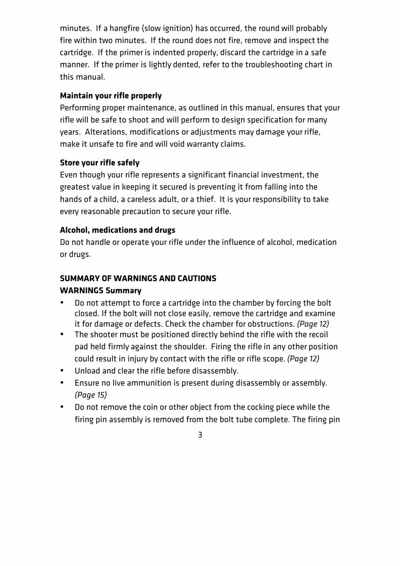
5. Rotate the cocking piece shroud counter clockwise about 120 degrees, or
1/3 of a turn (Figure 24, Step A.) and withdraw cocking piece (Figure 24,
Step B.) from the bolt carrier.
EDGE OF
RECOIL PAD
BOLT CARRIER
DISASSEMBLY TOOL
COCKING
PIECE
A
B
C
8/3/2019 MRAD Manual
http://slidepdf.com/reader/full/mrad-manual 27/45
26
Figure 24.
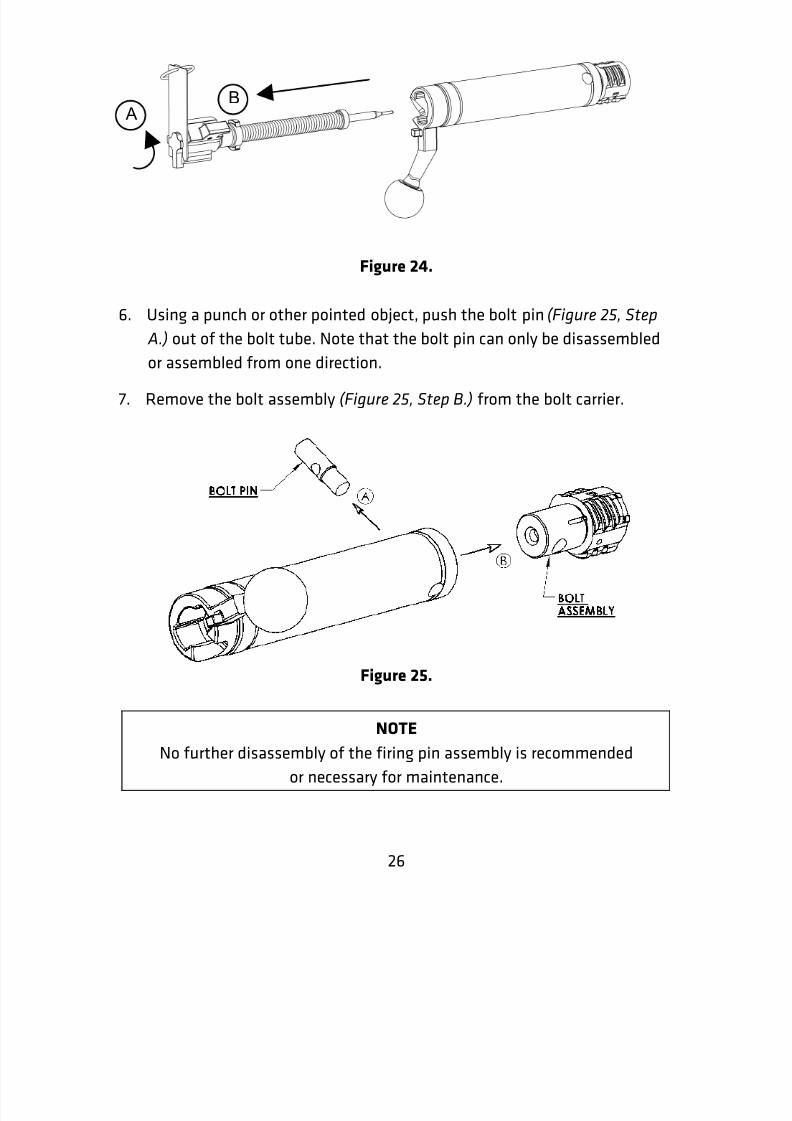
6. Using a punch or other pointed object, push the bolt pin (Figure 25, Step A.) out of the bolt tube. Note that the bolt pin can only be disassembled
or assembled from one direction.
7. Remove the bolt assembly (Figure 25, Step B.) from the bolt carrier.
Figure 25.
NOTE
No further disassembly of the firing pin assembly is recommended
or necessary for maintenance.
BA

8/3/2019 MRAD Manual
http://slidepdf.com/reader/full/mrad-manual 28/45
27
Reassembly of the bolt carrier assembly
Assembly is in the reverse order of its removal. Ensure that the hole in the
bolt pin is in line with the center hole of the bolt so that the firing pin can
pass through.
Disassembly and assembly of extractor
NOTE
If the rifle fails to extract or eject, rule out other causes before
attempting to remove the extractor spring or extractor. The removal of
these components are for replacement only.
Extractor removal
1. Bolt head must be removed from bolt carrier assembly before removing
the extractor.
2. Locate the end of the extractor spring. It is located just behind the bolt
lugs. (Figure 26.) It is a single bent wire.
3. Using a 1/16” punch, or similar pointed object, gently lift the end of theextractor spring and unwrap it counterclockwise from the bolt. With the
circular part of the spring up and fully out of the slot in the bolt, withdraw
the spring. (Figure 27.) Next slide the extractor out of the slot in the bolt.
(Figure 28.)
Figure 26.

8/3/2019 MRAD Manual
http://slidepdf.com/reader/full/mrad-manual 29/45
28
Figure 27.
Figure 28.
Extractor InstallationThe installation of the extractor is in reverse order of its removal. Insert the
straight leg of the spring into the slot (Figure 29, Step A.) and wrap the
circular part around the bolt. Ensure the end of the spring enters the extractor
pocket. Extractor must be properly oriented where the curve of the extractor
edge matched the bolt face. (Figure 28, Step B.)
Figure 29.
BA

8/3/2019 MRAD Manual
http://slidepdf.com/reader/full/mrad-manual 30/45
29
ADJUSTING THE TRIGGER MECHANISM
Removal of the trigger housing assembly
1. Rotate the safety lever half way between the stops on the receiver.
(Figure 30.) From the opposite side of the safety lever push and slightly
rotate, back and forth, the safety out of the receiver. This may require aflat punch, cartridge point, ink pen or other similar tool.
Figure 30.
(Removal of the Safety)
2. Separate the upper receiver from the lower receiver as described in thedisassembly section of this manual, “Disassembly Of Major Components”(Figure 10 and 11.)
3. Grasp the trigger housing assembly and slide the trigger housing assembly
rearward away from the magazine well opening and lift out of the
receiver. (Figure 31.)
SAFETY IN HALF-
ROTATED POSITION.
8/3/2019 MRAD Manual
http://slidepdf.com/reader/full/mrad-manual 31/45
30
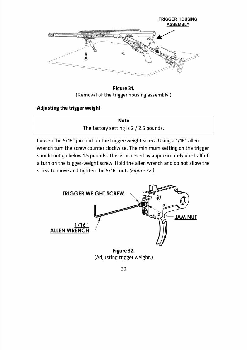
Figure 31. (Removal of the trigger housing assembly.)
Adjusting the trigger weight
Note
The factory setting is 2 / 2.5 pounds.
Loosen the 5/16” jam nut on the trigger-weight screw. Using a 1/16” allen
wrench turn the screw counter clockwise. The minimum setting on the trigger
should not go below 1.5 pounds. This is achieved by approximately one half of
a turn on the trigger-weight screw. Hold the allen wrench and do not allow the
screw to move and tighten the 5/16” nut. (Figure 32.)
Figure 32. (Adjusting trigger weight.)
TRIGGER HOUSING
ASSEMBLY

8/3/2019 MRAD Manual
http://slidepdf.com/reader/full/mrad-manual 32/45
31
Returning trigger weight to factory settings
Warning
Adjusting the trigger weight too low may cause an unintentional discharge.
1. Loosen the 5/16” jam nut on the trigger-weight screw. Turn the trigger-weight screw counter clockwise approximately four turns using a 1/16”allen wrench.
2. Pull the trigger and depress the sear. (Figure 33, Step A and B.) Turn thetrigger-weight screw clockwise until the plunger is fully compressed in thetrigger-weight screw. Turn the trigger-weight screw counter clockwise¼ turn and tighten the brass jam nut.
Figure 33. (Returning the trigger weight to the factory setting.)

8/3/2019 MRAD Manual
http://slidepdf.com/reader/full/mrad-manual 33/45
32
Adjusting the trigger over travel
NOTE
The trigger over travel is set to minimum from the factory
1. Loosen the¼” brass jam nut. Insert a 5/64” allen wrench into the over-travel screw.
2. Look through the hole in the side of the trigger housing and pull thetrigger and press down on the sear.
3. Turn the over-travel screw counter clockwise and observe the trigger
moving away from the sear.
4. Turn the screw until the desired over travel is achieved and lock into placeby turning the brass jam nut clockwise until it is tight against the triggerhousing. (Figure 34.)
5. Test the setting by pulling the trigger and depressing the sear. Releasethe trigger.
6. Slowly release the sear and ensure the trigger has enough clearance to
reset.
Figure 34.
(Adjusting the over travel.)

8/3/2019 MRAD Manual
http://slidepdf.com/reader/full/mrad-manual 34/45
33
Returning the over travel to the factory specifications
1. Loosen the¼” brass jam nut. Insert a 5/64” allen wrench into the over-travel screw.
2. Look through the hole in the side of the trigger housing and pull the
trigger and press down on the sear.
3. Turn the over-travel screw counter clockwise and observe the triggermoving away from the sear.
4. Turn the screw clockwise until it locks up the trigger against the sear.Turn the over travel screw counter clockwise one quarter of a turn andlock into place by turning the brass jam nut clockwise until it is tight
against the trigger housing. (Figure 35.)
5. Test the setting by pulling the trigger and depressing the sear. Releasethe trigger.
6. Slowly release the sear and ensure the trigger has enough clearance toreset.
Figure 35. (Resetting the over travel to the factory settings.)

8/3/2019 MRAD Manual
http://slidepdf.com/reader/full/mrad-manual 35/45
34
Installation of the trigger housing assembly into the receiver
1. Insert the trigger housing assembly into the slot in the lower receiver.(Figure 36, Step A.) Slide the trigger housing assembly forward and alignthe front of the trigger housing onto the pin in the receiver. (Figure 36,Step B.) Next align the safety hole in the lower receiver and the hole in
the trigger housing.
Figure 36. (Installation of the trigger housing.)
2. Insert the safety into the receiver until it stops on the safety detent.
Using the tip of a pen, cleaning rod or similar object, depress the safety
detent and finish inserting the safety into the receiver. The safety lever
must be halfway between the limiting stops on the lower receiver. (Figure
37.) The safety can be inserted on the opposite side to accommodate a
left-handed shooter. Installation is the same.

8/3/2019 MRAD Manual
http://slidepdf.com/reader/full/mrad-manual 36/45
35
Figure 37. (Installation of the safety.)
3. Ensure the bolt handle is in the up position. Close the receivers together.
Functional test of trigger
NOTEEnsure there is no live ammunition present during this test.
WARNING
Visually and physically check the chamber and make sure
the rifle is not loaded.
With the rifle fully assembled, slowly cycle the action of the rifle and pull thetrigger. Next, rapidly lift the bolt handle to the open position then back toclosed. Pull the trigger to make sure the trigger reset. If the trigger did notreset, adjust the trigger weight to heavier poundage by repeating the above
steps in the “Adjusting the trigger weight” section.

8/3/2019 MRAD Manual
http://slidepdf.com/reader/full/mrad-manual 37/45
36
CLEANING AND LUBRICATION
WARNINGUnload and clear the rifle before cleaning.
CAUTIONAlways clean from the chamber towards the muzzle. Do not insert cleaning
rods through the muzzle. The barrel crown could be damaged which wouldseverely degrade the accuracy of the rifle.
CAUTIONTo protect the rifle from corrosion, the rifle and the interior of the carrying
case should be moisture free before the rifle is placed in the carrying casefor storage.
Cleaning procedure
1. The rifle should be cleaned and lubricated after each shooting session.
Regular cleaning prevents the corrosive effects of moisture.
2. Apply cleaning solvent to a chamber brush and clean the chamber.
3. Apply cleaning solvent to a clean cotton patch and clean the bore fromthe chamber to the muzzle. Repeat until patches come out clean.
4. Use a stiff plastic brush to remove carbon from both the extractor and the
ejector. Depress the ejector and extractor by hand to test their smooth
function.
5. Use dry patches as necessary to remove cleaner from the bore and
chamber.
6. Clean the remainder of the rifle with cotton-tipped swabs, general-purpose brushes and rags. Apply light coating of preservative oil only to
exposed Barrel Assembly surfaces and Bolt lugs. In extremely dirty
conditions, a small amount of lubricant applied to the outside of the Bolt
Carrier will allow smoother function.

8/3/2019 MRAD Manual
http://slidepdf.com/reader/full/mrad-manual 38/45
37
PREVENTIVE MAINTENANCE CHECKS AND SERVICES
(Before, During and After Firing)
ITEMNO.
INTER-VAL
ITEM TO BECHECKED
PROCEDURE NOT READY ORAVAILABLE IF:
1 Before MRAD Hand cycle rifle to
ensure it is functi-onal and visuallycheck exterior of therifle and componentsfor damage. Checkcomponents forcracks, breaks, anddamage. Ensure allfasteners are tight. If
any faults are found,notify unitmaintenance.
Parts missing,
loose,damaged, orbroken.
2 Before MuzzleAdapter
Check to see that themuzzle adapter isfirmly secured to the
barrel and that itsports are parallel tothe ground when in a
level shootingposition.
Muzzleadapter isloose or
crooked.
3 Before BarrelAssembly
Check to ensure boreis free of obstruc-tion. Check for
excess lubrication inbore area. Swab dry.
Bore isobstructed.
4 Before Barrel Check headspace onbarrel using “Go” and
Field gages.
Bolt closes onField gage.
5 Before ReceiverAssembly
Pin
Check to see that theassembly pin is
securely installed.
Pin is missingor bent.
6 Before Magazine Ensure that the Free travel of

8/3/2019 MRAD Manual
http://slidepdf.com/reader/full/mrad-manual 39/45
38
magazine has freetravel of the followerand that themagazine body is notdamaged (bent or
cracked).
follower is notpresent ormagazine isdamaged.
7 BeforeandAfter
Magazine Ensure magazine isclean and dry.
Dirty or haslubricant in it.
8 During MuzzleAdapter
Check to see that themuzzle adapter issecured to the barreland that its ports are
parallel to theground when in alevel shootingposition.
Muzzleadapter isloose orcrooked.
9 During ReceiverAssemblyPin
Check to see that theassembly pin issecurely installed.
Pin is missingor bent.
10 During Magazine Ensure that themagazine has freetravel of the followerand that themagazine body is notdamaged (bent orcracked).
Free travel ofthe follower isnot present ormagazine isdamaged.
11 After MRAD Hand cycle rifle to
ensure it is funct-ional and visuallycheck exterior of the
rifle and componentsfor damage. Checkcomponents forcracks, breaks, anddamage. Ensure all
fasteners are tight.If any faults are
Parts missing,
loose,damaged, orbroken.

8/3/2019 MRAD Manual
http://slidepdf.com/reader/full/mrad-manual 40/45
39
found, notify unitmaintenance.
12 After MuzzleAdapter
Check to see that themuzzle adapter is
secured to the barrel
and that its ports areparallel to theground when in alevel shootingposition.
Muzzleadapter is
loose or
crooked.
13 After CleanBarrelBore
Clean chamber andbarrel boreimmediately after
firing.
Chamberand/or barrelobstructed.
14 After Barrel Check headspace onbarrel using “Go” andField gages.
Bolt closes onField gage
15 After ReceiverAssemblyPin
Check to see that theassembly pin issecurely installed.
Pin cannot beinserted farenough to be
secure.
Pin missing.
16 After Magazine Ensure the magazinehas free travel of thefollower and that themagazine body is notdamaged (bent or
cracked).
Free travel offollower is notpresent ormagazine isdamaged.
8/3/2019 MRAD Manual
http://slidepdf.com/reader/full/mrad-manual 41/45
40
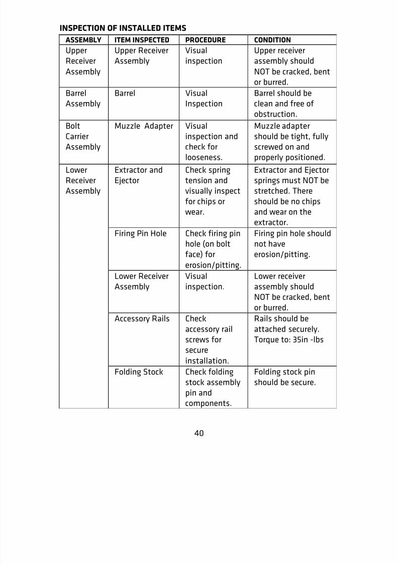
INSPECTION OF INSTALLED ITEMS
ASSEMBLY ITEM INSPECTED PROCEDURE CONDITION
UpperReceiver
Assembly
Upper ReceiverAssembly
Visualinspection
Upper receiverassembly should
NOT be cracked, bent
or burred.BarrelAssembly
Barrel VisualInspection
Barrel should beclean and free ofobstruction.
BoltCarrierAssembly
Muzzle Adapter Visualinspection andcheck forlooseness.
Muzzle adaptershould be tight, fullyscrewed on andproperly positioned.
Extractor andEjector
Check springtension andvisually inspectfor chips orwear.
Extractor and Ejectorsprings must NOT bestretched. Thereshould be no chipsand wear on theextractor.
Firing Pin Hole Check firing pin
hole (on boltface) for
erosion/pitting.
Firing pin hole should
not haveerosion/pitting.
Lower ReceiverAssembly
Visualinspection.
Lower receiverassembly shouldNOT be cracked, bentor burred.
Accessory Rails Checkaccessory railscrews forsecure
installation.
Rails should beattached securely.Torque to: 35in -lbs
LowerReceiverAssembly
Folding Stock Check foldingstock assemblypin and
components.
Folding stock pinshould be secure.

8/3/2019 MRAD Manual
http://slidepdf.com/reader/full/mrad-manual 42/45
41
TROUBLESHOOTING
MALFUNCTION CAUSE CORRECTIVE ACTION
Failure tochamberand lock
1. Damaged cartridge2. Dirty or obstructed
chamber
1. Remove and replacecartridge
2. Clean chamber
Failure tofire
1. Faulty ammunition2. Cocking piece shroud not
properly installed in bolt3. Cocking piece is dragging4. Firing pin or firing pin
spring broken or damaged
5. Bolt handle not down fully
1. Replace ammunition2. Assemble properly3. Clean and lubricate
cocking piece4. Turn in for repair.5. Ensure bolt handle is
down fully
Failure toextract
1. Broken or worn extractor2. Broken or worn extractor
spring3. Extractor not moving
freely4. Dirty ammunition or
chamber5. Broken case rim
6. Faulty Ammo
1. Replace extractor2. Replace extractor
spring3. Clean extractor,
extractor spring, andrecess
4. Clean chamber andensure ammunition is
clean5. Clear with cleaning
rod6. Replace ammunition,
cool if hot
Failure toeject
1. Broken or worn ejector2. Broken or worn ejector
spring
3. Ejector not moving freely
1. Turn in for repair2. Turn in for repair3. Turn in for repair.
Very hardrecoil
1. Faulty or hot ammunition2. Muzzle brake missing3. Improper shooter position4. Extractor not moving
freely.
1. Replace ammunition,cool if hot
2. Turn in for repair3. Firmly shoulder the
buttstock4. Ensure extractor is
properly installed

8/3/2019 MRAD Manual
http://slidepdf.com/reader/full/mrad-manual 43/45
42
MRAD EXPLODED VIEW

8/3/2019 MRAD Manual
http://slidepdf.com/reader/full/mrad-manual 44/45
43
MRAD PARTS LIST

8/3/2019 MRAD Manual
http://slidepdf.com/reader/full/mrad-manual 45/45
MRAD Parts List Continued


![Advanced Optics for Vision - Automate Lp/mm or Cy/mm Cy/mrad Lp/mm = 1 (f) Tan[(1000)(y/ mrad)]-1 Cy/mrad = 1 (1000) Tan ... Astigmatism = Essentially A Cylindrical Departure of The](https://static.fdocuments.us/doc/165x107/5e485ccd5bda80271568782f/advanced-optics-for-vision-automate-lpmm-or-cymm-cymrad-lpmm-1-f-tan1000y.jpg)