
MR330 Instruction Manual - Micronor
17
© COPYRIGHT 2016-2018, MICRONOR INC. CAMARILLO, CALIFORNIA UNITED STATES OF AMERICA FOTEMP1-OEM-MNT Manual Doc No: 98-OPTC-09 Revision A2 dated March-21-2018 MICRONOR INC. 900 Calle Plano, Suite K Camarillo, CA 93012 USA T +1-805-389-6600 F +1-805-389-6605 [email protected] www.micronor.com For Support in Europe: WEIDMANN TECHNOLOGIES DEUTSCHLAND GMBH Washingtonstrasse 16/16a D-01139 Dresden Germany T +49-351-843-5990 F +49-351-843-5991111 [email protected] www.optocon.de Notice of Proprietary Rights The design concepts and engineering details embodied in this manual, which are the property of MICRONOR INC. and WEIDMANN TECHNOLOGIES DEUTSCHLAND GMBH, are to be maintained in strict confidence; no element or detail of this manual is to be spuriously used, nor disclosed, without the express written permission of MICRONOR INC and WEIDMANN TECHNOLOGIES DEUTSCHLAND GMBH. All rights are reserved. No part of this publication may be reproduced, stored in a retrieval system, or transmitted in any form or by any means, electronic, mechanical, photocopying, recording, or otherwise, without prior written permission from MICRONOR INC and WEIDMANN TECHNOLOGIES DEUTSCHLAND GMBH.
Transcript of MR330 Instruction Manual - Micronor

© COPYRIGHT 2016-2018, MICRONOR INC.
CAMARILLO, CALIFORNIA UNITED STATES OF AMERICA
FOTEMP1-OEM-MNT Manual
Doc No: 98-OPTC-09 Revision A2 dated March-21-2018
MICRONOR INC. 900 Calle Plano, Suite K
Camarillo, CA 93012 USA T +1-805-389-6600 F +1-805-389-6605 [email protected] www.micronor.com
For Support in Europe:
WEIDMANN TECHNOLOGIES DEUTSCHLAND GMBH
Washingtonstrasse 16/16a D-01139 Dresden
Germany T +49-351-843-5990
F +49-351-843-5991111 [email protected] www.optocon.de
Notice of Proprietary Rights
The design concepts and engineering details embodied in this manual, which are the property of MICRONOR INC. and WEIDMANN TECHNOLOGIES DEUTSCHLAND GMBH, are to be maintained in strict confidence; no element or detail of this manual is to be spuriously used, nor disclosed, without the express written permission of MICRONOR INC and WEIDMANN TECHNOLOGIES DEUTSCHLAND GMBH. All rights are reserved. No part of this publication may be reproduced, stored in a retrieval system, or transmitted in any form or by any means, electronic, mechanical, photocopying, recording, or otherwise, without prior written permission from MICRONOR INC and WEIDMANN TECHNOLOGIES DEUTSCHLAND GMBH.

FOTEMP1-OEM-MNT Manual
Page 2 of 17
Revision History Revision Date Notes A 12/20/2016 Original Release A1 10/17/2017 Added FOTEMP1-OEM-MNT-4 (with 4-20mA output option) A2 3/21/2018 Corrected polarity of 4-20mA output connections

FOTEMP1-OEM-MNT Manual
Page 3 of 17
Table of Contents Table of Contents ...................................................................................................................... 3
Table of Figures ......................................................................................................................... 3
1. Product Description ............................................................................................................ 4
1.1 FOTEMP1-OEM-MNT .................................................................................................. 4
1.2 Fields of Applications ................................................................................................... 5
1.3 Features ....................................................................................................................... 5
1.4 Ordering Codes ........................................................................................................... 5
2. Specifications ...................................................................................................................... 6
2.1 OPTOCON SPI Protocol .............................................................................................. 8
2.2 Timing Diagrams .......................................................................................................... 9
2.3 Digital Input/Output Signal Requirements ................................................................. 10
2.4 Connections ............................................................................................................... 10
2.5 Application Specific Connections ............................................................................... 11
3. Operation.......................................................................................................................... 13
3.1 Contents .................................................................................................................... 13
3.2 SPI Test Connections ................................................................................................. 14
3.3 Temperature Calibration Using FOTEMP-ASSISTANT Software ................................. 15
3.4 FOTEMP-Assistant Software Installation ..................................................................... 15
4. Warranty Information ........................................................................................................ 16
5. Mechanical Reference Drawing ......................................................................................... 17
Table of Figures Figure 1. FOTEMP1-OEM-MNT PCB-Based Signal Conditioner/Controller. ................ 4 Figure 2: Various Views of Signal Conditioner .............................................................. 7 Figure 3: Timing Diagram of One Complete Read Access ........................................... 9 Figure 4: Oscilloscope Display Shows the "Data Gap" Between the Two Bytes .......... 9 Figure 5: FOTEMP1-OEM-MNT Interface Connections .............................................. 10 Figure 6: Location of DB9 RS232/SPI and J16 Power Connector ............................... 11 Figure 7: Front View and Pin-Outs of Female D89 Connector .................................... 11 Figure 8: Power Connections to J15 on FOTEMP-OEM-MNT .................................... 12 Figure 9: Connections to 4-20mA output on FOTEMP-OEM-MNT-4 ......................... 12 Figure 10: Key Contents of the FOTEMP Temperature System .................................. 13 Figure 11: Test Setup Shown With Micronor SPI Master Test Box .............................. 14

FOTEMP1-OEM-MNT Manual
Page 4 of 17
1. Product Description 1.1 FOTEMP1-OEM-MNT
Figure 1. FOTEMP1-OEM-MNT PCB-Based Signal Conditioner/Controller.
The FOTEMP-OEM-MNT is a small form factor PCB-sandwich module designed for low cost insertion of high precision GaAs-based fiber optic temperature sensor technology into OEM applications where common electrical temperature sensors and thermocouples cannot be used. This OEM product is compatible with all TS series fiber optic temperature probes. The sensors are entirely non-metallic and electrically passive, providing immunity to EMI, RFI, NMR, high voltage, microwaves and radiation The FOTEMP1-OEM-MNT PCB signal conditioner incorporates three digital interface; USB, RS232, and SPI. USB interface is Type B jack while RS232 and SPI share electrical interface connections via a DB9 connector.

FOTEMP1-OEM-MNT Manual
Page 5 of 17
1.2 Fields of Applications
• EMI, RFI, and Microwave Environments • High Voltage Environments • Harsh and Hazardous Environments • Nuclear Environments • Aerospace Applications • Process Monitoring • Medical Applications (MR)
1.3 Features
• Designed for OEM Integration • Very Small Size, Small Footprint • Modular Electronics Support Various Device Configurations • High Accuracy • Built in USB, RS232, and SPI Interface • Attractive OEM Volume Discounts
1.4 Ordering Codes Standard configurations typically available from stock: FOTEMP1-OEM-MNT 1-Channel Controller, USB/RS232/SPI, No Analog Output FOTEMP1-OEM-MNT -4 1-Channel Controller, USB/RS232/SPI, 4-20mA Output Contact Micronor sales concerning other configurations.

FOTEMP1-OEM-MNT Manual
Page 6 of 17
2. Specifications Table 1: FOTEMP-OEM-MNT Specifications Parameter Specification Optical Interface ST plug, Single input compatible with all TS Series fiber optic
temperature probes Fiber 200/220, 0.22NA Step Index Multimode Fiber Measuring Range Standard Calibration: -40°C to +300°C
Extended Calibration: -200°C to +300°C Internal Accuracy +/- 0.2°C Internal Sampling Rate 2 Hz Internal Resolution 0.1°C SPI Communication Protocol
SPI, Slave, Output Only, 16-bit packet (TI TMP123 format)
SPI Clock 1 MHz max OR 10 MHz max with 1µs delay between bytes Power Required 12 VDC, 350 mA Electrical Interface Power Connector (2-pin Molex): +V, GND
DB9 (Female): SPI (Ground, Clock, Serial Out, Chip Select); RS232 (RxD and TxD) USB via Type B receptacle 4-20mA (only available on FOTEMP1-OEM-MNT-4, 2pin Molex))
Operating Temperature Operating 0°C to +50°C, Storage -20°C to +70°C Humidity 0-95%, Non-condensing Ingress Protection IP00 Dimensions 100mm L x 80mm W x 34mm H

FOTEMP1-OEM-MNT Manual
Page 7 of 17
Figure 2: Various Views of Signal Conditioner
FOTEMP1-OEM-MNT Manual
Page 8 of 17
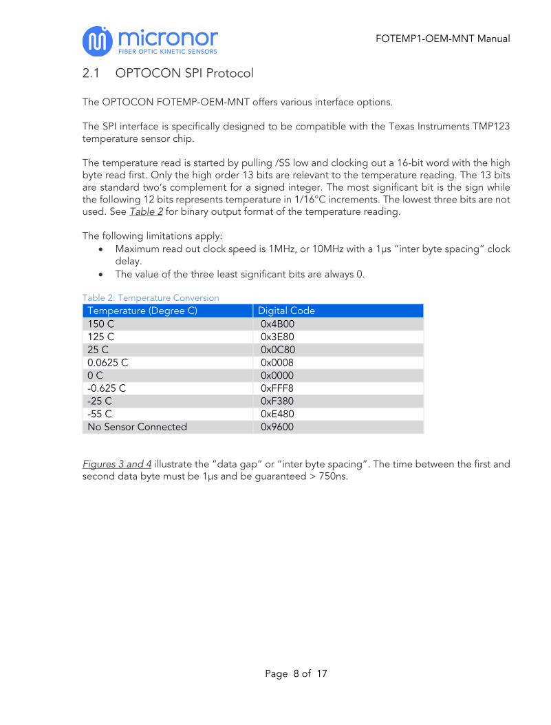
2.1 OPTOCON SPI Protocol The OPTOCON FOTEMP-OEM-MNT offers various interface options. The SPI interface is specifically designed to be compatible with the Texas Instruments TMP123 temperature sensor chip. The temperature read is started by pulling /SS low and clocking out a 16-bit word with the high byte read first. Only the high order 13 bits are relevant to the temperature reading. The 13 bits are standard two’s complement for a signed integer. The most significant bit is the sign while the following 12 bits represents temperature in 1/16°C increments. The lowest three bits are not used. See Table 2 for binary output format of the temperature reading. The following limitations apply:
• Maximum read out clock speed is 1MHz, or 10MHz with a 1µs “inter byte spacing” clock delay.
• The value of the three least significant bits are always 0. Table 2: Temperature Conversion Temperature (Degree C) Digital Code 150 C 0x4B00 125 C 0x3E80 25 C 0x0C80 0.0625 C 0x0008 0 C 0x0000 -0.625 C 0xFFF8 -25 C 0xF380 -55 C 0xE480 No Sensor Connected 0x9600
Figures 3 and 4 illustrate the “data gap” or “inter byte spacing”. The time between the first and second data byte must be 1µs and be guaranteed > 750ns.

FOTEMP1-OEM-MNT Manual
Page 9 of 17
2.2 Timing Diagrams
SCK
/SS
MOSI
MOSI
Temperature High Byte 0x12 Temperature Low Byte 0x34
Inter-byte spacing
Figure 3: Timing Diagram of One Complete Read Access
Figure 4: Oscilloscope Display Shows the "Data Gap" Between the Two Bytes

FOTEMP1-OEM-MNT Manual
Page 10 of 17
2.3 Digital Input/Output Signal Requirements Table 3: Digital Input/Output Electrical Characteristics Signal Condition Min Max Input Logic Levels
VCC = 2.7 - 3.6V
VIH 2 -- VIL -- 0.8V Output Logic Levels
VCC = 2.7 - 3.6V
VOL (IOL=2mA) -- 0.4V VOH (IOH=-2mA) 2.4V -- SPI Clock Frequency
-- 1 MHz or 10 MHz with 1µs
Spacing 2.4 Connections
Figure 5: FOTEMP1-OEM-MNT Interface Connections
ST Connection for TS
Temperature Probes
DSUB9 Connector provides
RS232 and SPI Interface
12V Power Connection
USB Interface
4-20mA Output (FOTEMP1-OEM-
MNT-4 Only)

FOTEMP1-OEM-MNT Manual
Page 11 of 17
2.5 Application Specific Connections
Figure 6: Location of DB9 RS232/SPI and J16 Power Connector Function: SPI and RS232 Connector: DB9, Female with 9x Socket Contacts Mating Connector: DB9 Male Plug with 9x Pin Contacts IMPORTANT NOTE: The RS232 signals uses 12V signals. A special cable must be used that does not connect pins 6-9 as the normal RS232 12V handshake signals appearing on these pins may damage the SPI 5V signals. Table 4: D89 Signal Connections Pin Signal Notes 1 Not connected 2 RxD (RS232) Data Out, RS232, DCE, 12V 3 TxD (RS232) Data In, RS232, DCE, 12V 4 Not connected 5 GND GND 6 MOSI (SPI) L2C, SPI, 5V 7 /SS (SPI) L1C, SPI, 5V 8 SCK (SPI) L4C, SPI, 5V 9 MISO (SPI) L3C, SPI, 5V
Figure 7: Front View and Pin-Outs of Female D89 Connector

FOTEMP1-OEM-MNT Manual
Page 12 of 17
Figure 8: Power Connections to J15 on FOTEMP-OEM-MNT Function: Power, J15 Connector: 2C Pin Header, Mating Connector: 2C, Socket Plug
Figure 9: Connections to 4-20mA output on FOTEMP-OEM-MNT-4 Function: 4-20mA Analog Output, J_MA Connector: 2C Pin Header, Mating Connector: 2C, Socket Plug

FOTEMP1-OEM-MNT Manual
Page 13 of 17
3. Operation 3.1 Contents
Figure 10: Key Contents of the FOTEMP Temperature System The FOTEMP1-OEM-MNT system contains the following:
• FOTEMP1-OEM-MNT Signal Conditioner • AC Power Supply (Upon request for engineering evaluation applications only) • CDROM with FOTEMP-ASSISTANT Software, USB Drivers and other support
documentation (not shown) Available Separately:
• TS Series Temperature Probes
TS Temperature Probe (Purchased Separately)
FOTEMP1-OEM-MNT Signal Conditioner

FOTEMP1-OEM-MNT Manual
Page 14 of 17
3.2 SPI Test Connections The system was connected and tested as shown in Figure 10. The Micronor SPI Master Emulator displays the both the TMP123-type binary reading and temperature in °C. From the FOTEMP signal conditioner.
Figure 11: Test Setup Shown With Micronor SPI Master Test Box Steps
1. Connect TS2 temperature probe to ST optical interface 2. Connect 12 V Power to J15 pin header 3. Connect SPI interface using DB9 Male Connector With Pin Contacts
FOTEMP1-OEM-MNT Signal Conditioner
TS Temperature
Probe

FOTEMP1-OEM-MNT Manual
Page 15 of 17
3.3 Temperature Calibration Using FOTEMP-ASSISTANT Software The FOTEMP1 will need to be calibrated with the actual temperature sensor used. This is achieved using a PC running the supplied FOTEMP-ASSISTANT graphical display/data logging software and connecting to the FOTEMP1 signal conditioner either via RS232 or USB interface. For more information regarding calibration using FOTEMP-Assistant please refer to the FOTEMP-ASSITANT2 Manual. 3.4 FOTEMP-Assistant Software Installation The FOTEMP-ASSISTANT V2 software is provided on the supplied CDROM. It will work with either USB or RS232 Interface For more information regarding the installation of FOTEMP-Assistant please refer to the FOTEMP-ASSITANT2 Manual. For RS232 operation
1. Connect the FOTEMP1 signal conditioner to the PC using Specially Wired RS232 cable. This special cable has Pins 6-9 disconnected so that the 12V RS232 signals do not damage the 5V SPI signals wired to these DB9 pins.
2. Click on the Program File and then [PortSettings]. Be sure that COM1 is selected. 3. Select [OK] and then [Connect] to start the program. After a few seconds, the program
should start and display temperature. For USB operation
1. Connect the FOTEMP1 signal conditioner to the PC using supplied USB cable. If Windows tells you that the device has been properly installed, then continue to Step 3.
2. Disconnect the USB cable. Windows was not able to load the correct Virtual Comm Port (VCP) drivers for the FTDI serial interface chip. You will need to install VCP drivers (either 32-bit or 64-bit depending on your system) supplied on the CD. Then repeat Step 1.
3. Click on the Program File and then [PortSettings]. Select the COMx port that corresponds to VCP assigned to the FOTEMP unit.
4. Select [OK] and then [Connect] to start the program. After a few seconds, the program should start and display temperature.
5. If the program will not start, then contact Micronor for assistance. Note: If developing custom communications software, contact Micronor for ASCII Protocol. Sample National Instruments LabVIEW™ Driver is also available.

FOTEMP1-OEM-MNT Manual
Page 16 of 17
4. Warranty Information Warranty MICRONOR INC. warrants this product to be free from defects in material and workmanship for a period of 1 (one) year from date of shipment. During the warranty period we will, at our option, either repair or replace any product that proves to be defective. To exercise this warranty, write or call your local MICRONOR INC. representative, or contact MICRONOR INC. headquarters. You will be given prompt assistance and return instructions. Send the instrument, transportation prepaid, to the indicated service facility. Repairs will be made and the instrument returned transportation prepaid. Repaired products are warranted for the balance of the original warranty period, or at least 90 days. Limitations of Warranty This warranty does not apply to defects resulting from unauthorized modification or misuse of any product or part. This warranty also does not apply to Fiber Optic Connector interfaces, fuses or AC line cords. This warranty is in lieu of all other warranties, expressed or implied, including any implied warranty of merchantability of fitness for a particular use. MICRONOR INC. shall not be liable for any indirect, special or consequent damages. Contact Information: Micronor Inc. Phone +1-805-389-6600 900 Calle Plano, Suite K Fax +1-805-389-6605 Camarillo, CA 93012 Email sales@micronor,com USA URL www.micronor.com For Europe: Weidman Technologies Deutschland GmbH Phone +49-351-843-5990 Washingtonstrasse 16/16a Fax +49-351-843-5991111 D-01139 Dresden Email [email protected] GERMANY URL www.optocon.de

FOTEMP1-OEM-MNT Manual
Page 17 of 17
5. Mechanical Reference Drawing