MR2 Spyder 2AR-FE Swap Wiring Instructions...Page 1 MR2 Spyder 2AR-FE Swap Wiring Instructions The...
13
Page 1 MR2 Spyder 2AR-FE Swap Wiring Instructions The MR2 Spyder 2AR-FE swap uses a junction box circuit board to replace the contents of the stock ECU and the two following jumpers are used along with a reworked Scion TC engine harness in order to complete the wiring for the car. This documentation is provided as an alternative for those that would rather make their own wiring harness instead of purchasing the Frankenstein Motorworks plug and play solution. This is also the exact same pinout as the solution I sell so it can be used if diagnosis is ever needed. Contents Junction box: ................................................................................................... 2 Junction Box to ECU jumper: ........................................................................... 3 Junction Box to DBW & OBDII: ........................................................................ 4 2ar-fe Engine harness rework: ........................................................................ 5 Appendix A: Sources for connectors ............................................................. 10 Appendix B: How to remove and insert a terminal from a connector .......... 11 All connector layout images in this document are documented as if you’re looking at the connector from the pin side, not the wire side. Feel free to reach out to [email protected] with questions about this documentation or any other part of the 2AR-FE swap into the MR2 spyder.
Transcript of MR2 Spyder 2AR-FE Swap Wiring Instructions...Page 1 MR2 Spyder 2AR-FE Swap Wiring Instructions The...

Page 1
MR2 Spyder 2AR-FE Swap Wiring Instructions
The MR2 Spyder 2AR-FE swap uses a junction box circuit board to replace the contents of the stock ECU and the two following jumpers are used along with a reworked Scion TC engine harness in order to complete the wiring for the car. This documentation is provided as an alternative for those that would rather make their own wiring harness instead of purchasing the Frankenstein Motorworks plug and play solution. This is also the exact same pinout as the solution I sell so it can be used if diagnosis is ever needed.
Contents Junction box: ................................................................................................... 2
Junction Box to ECU jumper: ........................................................................... 3
Junction Box to DBW & OBDII: ........................................................................ 4
2ar-fe Engine harness rework: ........................................................................ 5
Appendix A: Sources for connectors ............................................................. 10
Appendix B: How to remove and insert a terminal from a connector .......... 11
All connector layout images in this document are documented as if you’re looking
at the connector from the pin side, not the wire side.
Feel free to reach out to [email protected] with questions
about this documentation or any other part of the 2AR-FE swap into the MR2
spyder.

Page 2
Junction box: The junction box is a circuit board that gets installed in the stock ECU case and makes wiring this swap
much easier. In the near future it will also provide BEAN network functionality for A/C and gauge cluster
functionality. Both versions use the same circuit board, the non BEAN version simply does not have the
components populated on the board.

Page 3
Junction Box to ECU jumper: This jumper connects between the junction box and the small plug on the 2AR-FE ECU.
E5 A35
Wire as follows:
Pin Name A35 E5 Gauge
Pin Name A35 E5 Gauge
+B2 1 31 16
IGSW 28 30 20
+B 2 21 16
STP 29 15 20
BM+ 3 1 16
ELS1 31 5 18
CANL 5 28 20
EC 32 29 18
MREL 6 14 20
W 36 17 20
TC 7 25 20
ST1 39 16 20
FC 8 8 20
CCS 40 20 20
CG 9 18 20
ELS3 41 6 20
CANH 13 27 20
VPA 55 10 20
VSS 15 26 20
VPA2 56 11 20
BATT 20 9 16
VCPA 57 12 20
FANL 21 3 18
VCP2 58 13 20
FANH 22 4 18
EPA 59 22 20
Tach 26 24 20
EPA2 60 23 20

Page 4
Junction Box to DBW & OBDII: This jumper connects the junction box to the DBW pedal and also provides the OBDII port. Note that
there are extra pins on the junction box, these are provided to assist with installations that do not use
the stock gauge cluster. It is safe to ignore these extra pins if they are not needed.
A2 17P OBDII
Wire as follows: Pin Name A2 17P OBDII Gauge
TACH
2 9 20
Check Engine
3
20
GND
4 5 18
Alternator Light
5
20
Oil Press
6
20
B+
7 16 18
TC
8 13 20
VCP2 4 9
20
VCPA 6 10
20
VPA2 2 11
20
VPA 5 12
20
CANL
13 14 20
CANH
14 6 20
GND
15 4 18
EPA2 1 16
20
EPA 3 17
20
Note1: the CANH and CANL wires need to be twisted together approximately one to two twists per inch.
Alternately they can be run inside a metal shield grounded at only at the 17P plug end.
Note2: The car already contains an OBDII connector but it does not have the pins required for the CAN
bus. If desired the CAN wires could be wired to the stock OBDII connector with appropriate pins added
and everything would work as intended.

Page 5
2ar-fe Engine harness rework: This section is for starting with manual transmission 2011-2016 Scion TC engine harness part number
82121-21540. Note that starting with an automatic transmission harness is not significantly different
from these instructions but it is not currently documented.
We will only be modifying part of the harness to the right of line “A” in this diagram
The connectors labeled above are:
1) Reverse connector, this will be remaining
2) Starter power. This will be removed from the harness but the wire will be modified and used.
3) Starter solenoid, this will be remaining
4) This is the battery terminal side of the starter power (#2 in the diagram), it will be removed
5) This is power to the Scion TC fuse box. This will be removed
6) This is the alternator charging wire. This will be modified lightly and fit into the scion TC fuse box
7) This is the other end of #5, it will also be removed.
8) This connector is the BA1 connector that will need to be remapped into the Spyder’s harness.
9) This is the BA2 connector that will need to be remapped into the Spyder’s harness.
10) This is the BA3 connector that will need to be remapped into the Spyder’s harness.

Page 6
This is the pinout on the BA1, BA2 and BA3 wires. Note that the wire colors are provided but some of
the colors are reused so this swap cannot be wired strictly by color.
BA1 Pin Numbering and Functions:
BA2 Pin Numbering and Functions:
BA3 Pin Numbering and Functions:
All 22 of these wires should get labeled by function and depinned from the scion TC housings in
preparation for insertion into the Spyder’s connector housings.
Page 7
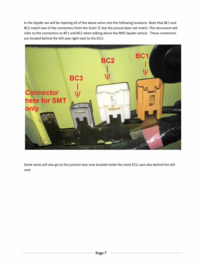
In the Spyder we will be repining all of the above wires into the following locations. Note that BC1 and
BC2 match two of the connectors from the Scion TC but the pinout does not match. This document will
refer to the connectors as BC1 and BC2 when talking about the MR2 Spyder pinout. These connectors
are located behind the left seat right next to the ECU:
Some wires will also go to the junction box now located inside the stock ECU case also behind the left
seat.

Page 8
The following is how BC1, BC2, BC3 and E4 should be pinned. Wire colors given in these pictures are the
Scion TC colors. Note that there are extra pin names that are not from the scion TC harness, These will
be found in pairs and simply mean that a jumper should be placed between these two pins. For example
“DRL” is a wire that goes from BC3 to E4 and does not go into the engine harness but becomes part of
this new combined harness. The wire colors for those new wires are just suggestions.
BC1 Pin Numbering and Functions:
BC2 Pin Numbering and Functions:

Page 9
BC3 Pin Numbering and Functions:
*note, if the DRL pin is left out it will disable daytime running lights. This can be done with no side
effects.
E4 Pin Numbering and Functions:

Page 10
Appendix A: Sources for connectors
The connectors needed for the above work can be sourced from several places, it’s generally
exceedingly expensive to buy them from Toyota directly. Their housings are reasonably priced but the
wire pigtails are absurdly priced. I’ve found the following is the best way to aquire all the connectors if
you choose to not buy the pre-made harnesses from Frankenstein Motorworks:
E5: This connector does not need to be sourced, it exists on the 1zz engine harness that has been
removed from the car to make room for this swap
A35: This connector is best gotten at the same time as the engine is sourced. It can often be picked up
for free with the purchase of the engine. It can also be purchased at a very reasonable cost from
Frankenstein Motorworks: https://frankensteinmotorworks.squarespace.com/mr2-spyder-shop/2-plug-
ecu-small-pigtail and you can also search e-bay for 90920-12588, that’s the part number for the lever
not the connector but it’s the part number that most listings use, sometimes they are quite cheap on e-
bay.
A2: This connector is actually shared with the idle control motor on the 1JZ and 2JZ and has huge
aftermarket support. Searching the internet for “2JZ IACV connector” returns a ton of links at reasonable
prices.
17P: This connector is on many early 90’s Toyota ECUs but there is no really reliable place to get it. The
easiest way to get this is to order 90980-11586 from the dealer, this will give you the housing without
wires for about $10 and wires pigtails can be salvaged from the stock ECU connector to wire it up.
OBDII: This is just an industry standard connector. Searching the internet for “OBDII connector” will
result in many cheap options.

Page 11
Appendix B: How to remove and insert a terminal from a connector
Officially the tool you need to remove the terminals on the connectors needed for this work has these dimensions:
That exact style terminal extractor is expensive but this alternative works well: https://www.amazon.com/beler-Terminal-Maintenance-Fulfilled-hermeshine/dp/B071CVMBBB With
this set there are two tools that are chisel shaped with very similar dimensions to the above mentioned “official” tool dimensions and two others that are “V” shaped that work great for lifting locks.
To remove a pin from a connector first disengage the secondary locks if there is one. Note that the secondary lock only lifts up a little and does not fully get removed. Be careful when working with a connector with a secondary lock because it is easy to accidentally relock it without noticing it and the terminals won’t be possible to remove.

Page 12
Once the secondary lock is disengaged, the retainer on each terminal can be disengaged to remove one wire using the following instructions. Here is a cross section of one wire in the housing and how it is retained, to release the wire we need to lift the retainer and the wire pulls out. Note that you need to lift the retainer before pulling the wire, if there is tension on the wire before lifting the retainer it will be very difficult to lift the retainer.
1) Place the tool in the small opening between the terminal and the retainer, being careful to align the chisel point as indicated by the picture:

Page 13
2) Pivot the tool against the end of the terminal to raise the retainer, it isn’t necessary to raise the retainer until it hits the top of the housing, this usually just results in the tool slipping off the retainer.
3) Pull on the wire gently to remove it. There should be no resistance to removing the wire and terminal. If there is resistance it is likely the retainer or secondary lock is not fully disengaged. Push the wire back in and go back to the start.
4) note that once the terminal has moved more than 1-2mm the retainer no longer needs to be held up and can be removed
If a secondary lock was unlocked at the beginning don’t forget to push it back in after the work is done.