MQXF Design and Conductor Requirements P. Ferracin MQXF Conductor Review November 5-6, 2014 CERN.
34
MQXF Design and Conductor Requirements P. Ferracin MQXF Conductor Review November 5-6, 2014 CERN
-
Upload
donald-harris -
Category
Documents
-
view
218 -
download
2
Transcript of MQXF Design and Conductor Requirements P. Ferracin MQXF Conductor Review November 5-6, 2014 CERN.

MQXF Design and Conductor Requirements
P. Ferracin
MQXF Conductor Review November 5-6, 2014
CERN

Outline
• Overview of MQXF design
• Baseline strand and insulated cable
• Coil design and magnetic analysis
• Magnet parameters
• Mechanical analysis and quench protection
5/11/2014Paolo Ferracin 2

Overview of MQXF design
5/11/2014Paolo Ferracin 3
• Target: 140 T/m in 150 mm coil aperture
• To be installed in 2023 (LS3)
• Q1/Q3 (by US LARP collaboration)– 2 magnets with 4.0 m of magnetic
length within 1 cold mass• Q2 (by CERN)
– 1 magnet of 6.8 m within 1 cold mass, including MCBX (1.2 m)
• Baseline: different lengths, same design– Identical short model magnets SQXF
by E. Todesco
20 40 60 80 100 120 140 160 180distance to IP (m)
Q1 Q3Q2a Q2b D1
Q1-3: 140 T/mMCBX: 2.2 T 2.5/4.5 T mD1: 5.6 T 35 T mD2: 4.5 T 35 T mQ4: 115 T/mMCBY: 3 T 4.5 T m
D2 Q4

From LARP HQ to MQXFStrand, cable and coil
• The aperture/cable width is approximately maintained– Aperture from 120 mm to 150 mm– Cable from 1.5 to 1.8 mm width– Similar stress with +30% forces
• Same coil lay-out: 4-blocks, 2-layer with same angle• Optimized stress distribution
• Strand increase from 0.778 mm to 0.85 mm– Same filament size from 108/127 to 132/169– Maximum # of strands: 40
• Lower Joverall from quench protection (from 580 to 480 A/mm2)
5/11/2014Paolo Ferracin 4
HQ MQXF

From LARP HQ to MQXFMagnet design
• Same structure concept • Pre-load capabilities of HQ design qualified and successfully tested
• Larger OD: from 570 to 630 mm• Additional accelerator features
• Larger pole key for cooling holes• Cooling channels• Slots for assembly/alignment • LHe vessel and welding blocks and slots
5/11/2014Paolo Ferracin 5
HQ MQXF
Overview of MQXF design
5/11/2014Paolo Ferracin 6
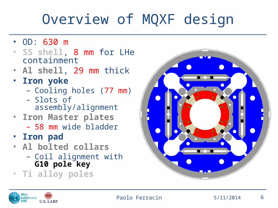
• OD: 630 m• SS shell, 8 mm for LHe
containment• Al shell, 29 mm thick• Iron yoke
– Cooling holes (77 mm) – Slots of assembly/alignment
• Iron Master plates – 58 mm wide bladder
• Iron pad• Al bolted collars
– Coil alignment with G10 pole key
• Ti alloy poles
Overview of MQXF design
5/11/2014Paolo Ferracin 7
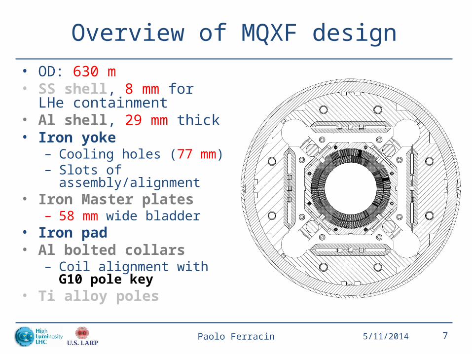
• OD: 630 m• SS shell, 8 mm for LHe
containment• Al shell, 29 mm thick• Iron yoke
– Cooling holes (77 mm) – Slots of assembly/alignment
• Iron Master plates – 58 mm wide bladder
• Iron pad• Al bolted collars
– Coil alignment with G10 pole key
• Ti alloy poles
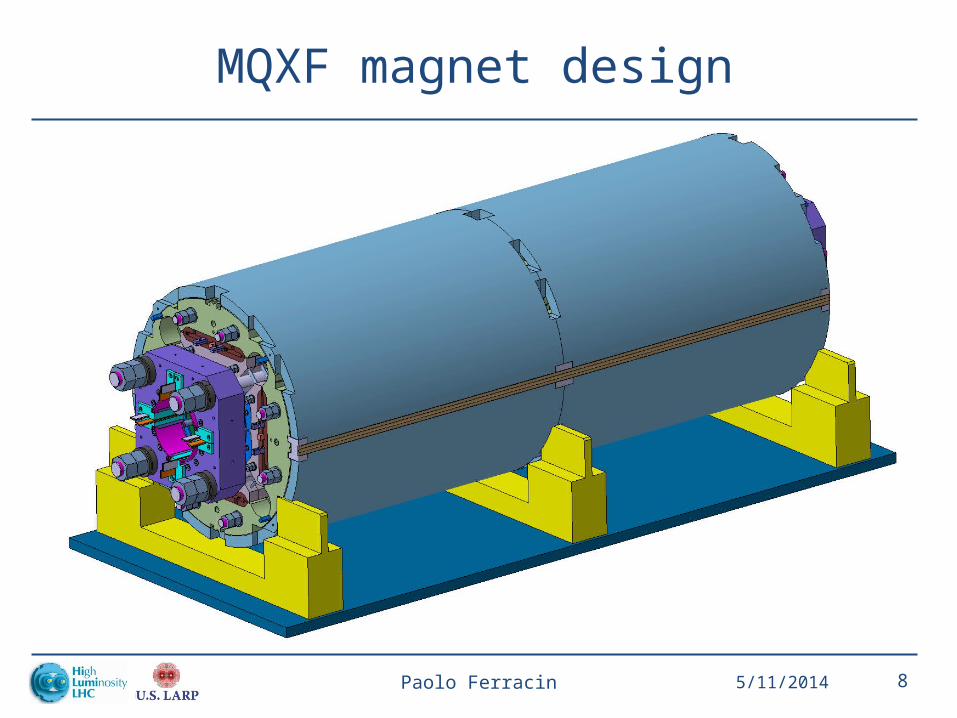
MQXF magnet design
5/11/2014Paolo Ferracin 8

Outline
• Overview of MQXF design
• Baseline strand and insulated cable
• Coil design and magnetic analysis
• Magnet parameters
• Mechanical analysis and quench protection
5/11/2014Paolo Ferracin 9

• 0.85 mm strand
• Filament size <50 μm• OST 132/169: 48-50 μm• Bruker PIT 192: 42 μm
• Cu/Sc: 1.2 0.1 55% Cu
• Critical current at 4.2 K and 15 T– 361 A at 15 T
MQXF strand(from CERN technical specification document)
5/11/2014Paolo Ferracin 10
Bruker PIT strand, 192
OST RRP strand, 132/169

MQXF baseline cable and insulation
5/11/2014Paolo Ferracin 11

MQXF baseline cable
• 40-strand cable• Mid – thickness after cabling
– 1.525 +/- 0.010 mm– Thin/thick edge: 1.438 /1.612 mm
• Width after cabling– 18.150 +/- 0.050 mm
• Keystone angle– 0.55 +/- 0.10 deg.
– Pitch length– 109 mm
– SS core 12 mm wide and 25 μm thick
• Assumed expansion during reaction– 4.5% in thickness: ~70 μm, same
keystone angle– 2% in width: ~360 μm
• Mid – thickness after reaction– 1.594 mm– Thin/thick edge: 1.505/1.682 mm
• Width after reaction– 18.513 mm
5/11/2014Paolo Ferracin 12
PIT
cable R
RP
cable
70 μm
360 μm
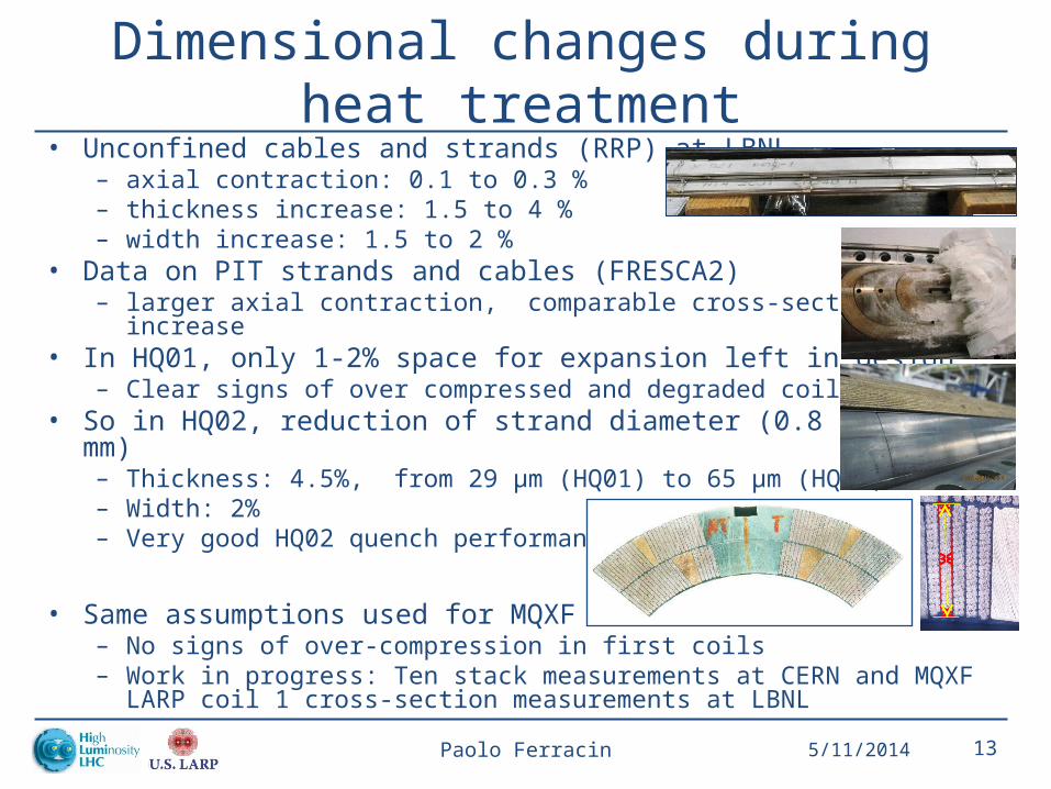
Dimensional changes during heat treatment• Unconfined cables and strands (RRP) at LBNL
– axial contraction: 0.1 to 0.3 %– thickness increase: 1.5 to 4 %– width increase: 1.5 to 2 %
• Data on PIT strands and cables (FRESCA2) – larger axial contraction, comparable cross-section increase
• In HQ01, only 1-2% space for expansion left in design– Clear signs of over compressed and degraded coils
• So in HQ02, reduction of strand diameter (0.8 0.778 mm)– Thickness: 4.5%, from 29 μm (HQ01) to 65 μm (HQ02)– Width: 2%– Very good HQ02 quench performance
• Same assumptions used for MQXF– No signs of over-compression in first coils– Work in progress: Ten stack measurements at CERN and MQXF LARP coil 1 cross-
section measurements at LBNL
5/11/2014Paolo Ferracin 13
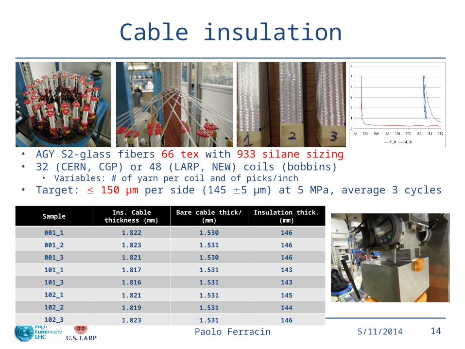
Cable insulation
• AGY S2-glass fibers 66 tex with 933 silane sizing• 32 (CERN, CGP) or 48 (LARP, NEW) coils (bobbins)
• Variables: # of yarn per coil and of picks/inch• Target: 150 μm per side (145 5 μm) at 5 MPa, average 3 cycles
5/11/2014Paolo Ferracin 14
Sample Ins. Cable thickness (mm) Bare cable thick/ (mm) Insulation thick. (mm)
001_1 1.822 1.530 146
001_2 1.823 1.531 146
001_3 1.821 1.530 146
101_1 1.817 1.531 143
101_3 1.816 1.531 143
102_1 1.821 1.531 145
102_2 1.819 1.531 144
102_3 1.823 1.531 146

Tooling design
• Cable dimension after reaction and 150 μm thick insulation
• Coil cured in larger cavity
• Coil closed in reaction fixture in larger cavity
• Coil after reaction and during impregnation in nominal cavity
• Theoretical pressure ~5 MPa
5/11/2014Paolo Ferracin 15
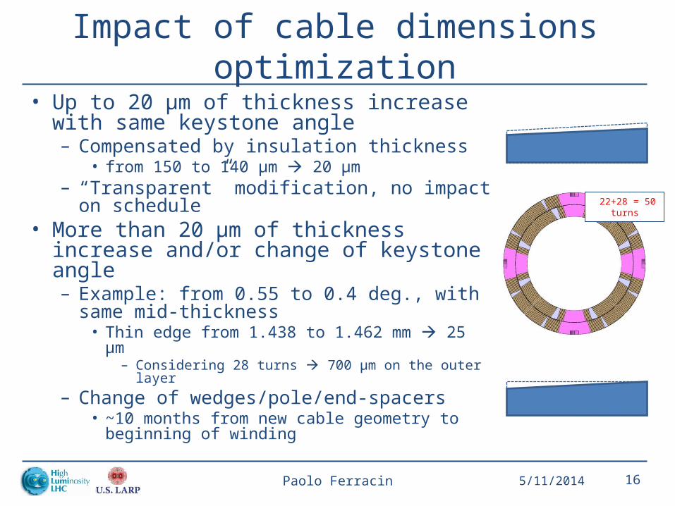
Impact of cable dimensions optimization• Up to 20 μm of thickness increase with same
keystone angle– Compensated by insulation thickness
• from 150 to 140 μm 20 μm– “Transparent” modification, no impact on
schedule• More than 20 μm of thickness increase
and/or change of keystone angle– Example: from 0.55 to 0.4 deg., with same mid-
thickness• Thin edge from 1.438 to 1.462 mm 25 μm
– Considering 28 turns 700 μm on the outer layer– Change of wedges/pole/end-spacers
• ~10 months from new cable geometry to beginning of winding
5/11/2014Paolo Ferracin 16
22+28 = 50 turns
Outline
• Overview of MQXF design
• Baseline strand and insulated cable
• Coil design and magnetic analysis
• Magnet parameters
• Mechanical analysis and quench protection
5/11/2014Paolo Ferracin 17

Coil design and magnetic analysis• Two-layer – four-block design, 22+28 = 50 turns• Criteria for the selection
– Maximize gradient and # of turns (protection) – Distribute e.m. forces and minimize stress
• All harmonics below 1 units at Rref = 50 mm
• 6 blocks in the ends• 1% peak field margin in the end (ss pad)
5/11/2014Paolo Ferracin 18

Persistent currents• Estimates using magnetization measurements of actual QXF
169 wires performed at Ohio State University• Harmonics are provided for second up-ramp following a pre-
cycle corresponding to the one used for strand measurements
5/11/2014Paolo Ferracin 19
Measured magnetization (OSU) Calculated b6 (after pre-cycle)

Persistent-current effect evaluation
• Effect of ±20% magnetization on b6, b10 included– Nominal b6 value of -10 units can be adjusted using current reset level
during pre-cycle– Dynamic aperture simulations have validated a persistent current b6 up
to 20 units at injection• Present value of magnetization average and spread are compatible
with field quality requirements
• For future study: assessment of the variability in wire magnetization and resulting uncertainty and random harmonics
5/11/2014Paolo Ferracin 20
Persistent current harmonics
b6 b10
Nominal D(+20%M) Nominal D(+20%M)
1.0 kA (injection) -10.0 -2.4 3.4 +0.8
17.5 kA (high field) -0.97 -0.12 -0.1 0.0

Coil design and magnetic analysisMagnet lengths
5/11/2014Paolo Ferracin 21
Magnetic length RT = 1198 mm
Coil design and magnetic analysisMagnet lengths
5/11/2014Paolo Ferracin 22
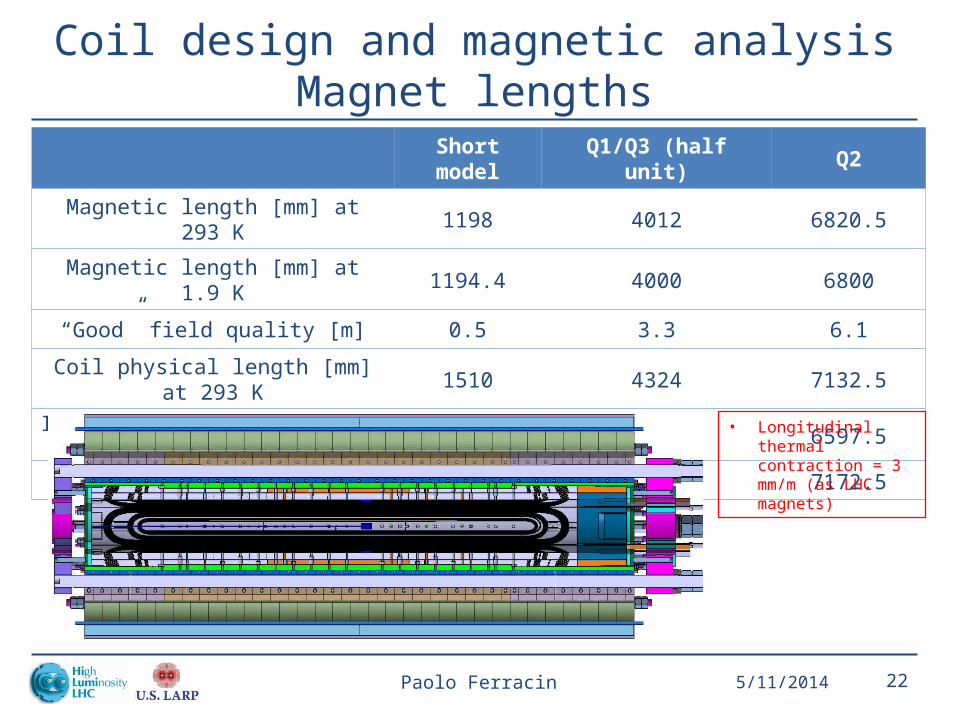
Short model Q1/Q3 (half unit) Q2
Magnetic length [mm] at 293 K 1198 4012 6820.5
Magnetic length [mm] at 1.9 K 1194.4 4000 6800
“Good” field quality [m] 0.5 3.3 6.1
Coil physical length [mm] at 293 K 1510 4324 7132.5
Iron pad length [mm] at 293 K 975 3789 6597.5
Yoke length [mm] at 293 K 1550 4364 7172.5
• Longitudinal thermal contraction = 3 mm/m (as LHC magnets)

Coil design and magnetic analysisConductor quantities
5/11/2014Paolo Ferracin 23
Short model Q1/Q3 (half unit) Q2
Cable length per coil [m] (Roxie) 126 407 687
Cable length per coil [m] (with margin) 150 450 710
Strand per coil [km] (with margin) 6.3 18.9 30.0
Strand per coil [kg] (with margin) 32 95 150
• Strand length = cable length * 40 * 1.05• 1 km of 0.85 mm strand: 5 Kg.

Outline
• Overview of MQXF design
• Baseline strand and insulated cable
• Coil design and magnetic analysis
• Magnet parameters
• Mechanical analysis and quench protection
5/11/2014Paolo Ferracin 24
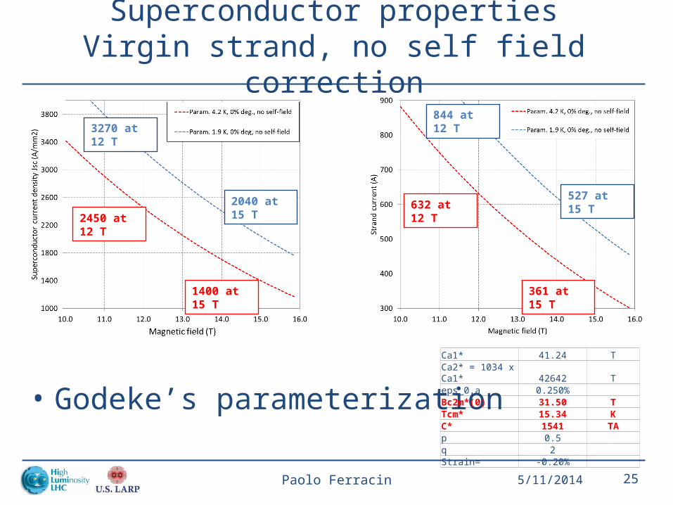
Superconductor propertiesVirgin strand, no self field correction
• Godeke’s parameterization
5/11/2014Paolo Ferracin 25
2450 at 12 T
1400 at 15 T
2040 at 15 T
3270 at 12 T
632 at 12 T
361 at 15 T
527 at 15 T
844 at 12 T
Ca1* 41.24 TCa2* = 1034 x Ca1* 42642 Teps_0,a 0.250% Bc2m*(0) 31.50 TTcm* 15.34 KC* 1541 TAp 0.5 q 2 Strain= -0.20%
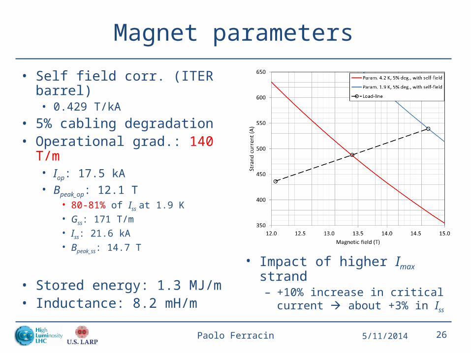
Magnet parameters
• Self field corr. (ITER barrel)• 0.429 T/kA
• 5% cabling degradation• Operational grad.: 140 T/m
• Iop: 17.5 kA• Bpeak_op: 12.1 T
• 80-81% of Iss at 1.9 K• Gss: 171 T/m• Iss: 21.6 kA• Bpeak_ss: 14.7 T
• Stored energy: 1.3 MJ/m• Inductance: 8.2 mH/m
5/11/2014Paolo Ferracin 26
• Impact of higher Imax strand – +10% increase in critical
current about +3% in Iss

Magnet parameters
• Temperature margin (K) • Peak field (T)
5/11/2014Paolo Ferracin 27

Outline
• Overview of MQXF design
• Baseline strand and insulated cable
• Coil design and magnetic analysis
• Magnet parameters
• Mechanical analysis and quench protection
5/11/2014Paolo Ferracin 28

Mechanical analysis• ≥2 MPa of contact pressure at up to
155 T/m (~90% of Iss)
• Peak coil stress: -160/-175 MPa
• Strain effect not included in Iss computation• Similar stress as HQ• ~20% of margin
5/11/2014Paolo Ferracin 29
Inner layer
Outer layer

Quench protection
5/11/2014Paolo Ferracin 30
• Protection studied in the case of 2 magnets in series (16 m) protected by one dump resistor (48 mΩ, 800 V maximum voltage)– Voltage threshold: 100 mV– Cu/Non-Cu: 1.2 – Validation time: 10 ms– Protection heaters on the outer and on the inner layer
• Hot spot T with 1.2 Cu/Non-Cu ratio: ~263 K
• Negligible effect of ~6-7 K from RRR (100-200) and Cu/non-Cu ratio (1.1 to 1.2)

Conclusions• Strand critical current of 361 A at 15 T
– Corresponding to current density of ~2500 A/mm2 at 12 T– ~80-81% of Iss
• Reasonable margin, probably the most critical parameter– 10% of critical strand current 3% of load-line margin
• Cu/non-Cu of 1.2– In HQ: 1.1-1.2
• Intermediate value between 0.85 (HD) and 1.6 (LHC) – Safe margin for protection
• Filament size <50 μm– Same filament size as one used in HQ02 successfully tested– Consistent with field quality requirements
• Cored cable required for reduction of dynamics effects (as in HQ02)
• Peak stress of ~170 MPa, similar to TQ/HQ series
5/11/2014Paolo Ferracin 31

Appendix
5/11/2014Paolo Ferracin 32

MQXF project schedule
5/11/2014Paolo Ferracin 33
• Short model program: 5 CERN-LARP models, 2014-2016– Coil fabrication starts in 02-03/2014– First magnet test (SQXF1) in 07/2015 (3 LARP coils, 1 CERN coil)
• Long model program: 2 (CERN) + 3 (LARP) models, 2015-2018– Coil fabrication starts in 2015: 02 (LARP), 10 (CERN)– First magnet test in 08/2016 (LARP) and 07/2017 (CERN)
• Series production: 10 (CERN) + 10 (LARP) cold masses, 2018-2021– Coil fabrication starts in 01/2018– First magnet test in 10/2019

Impact of cable dimensions optimizationCERN MQXF current schedule
5/11/2014Paolo Ferracin 34
2014 2015 2016 2017 2018
RRP short model 1
RRP short model 2
PIT short model 1
RRP long model 1
PIT long model 1