MP-XP7230GB/MP-XP5230GB - tim.id.autim.id.au/laptops/jvc/jvc mini note mp-xp7230gb 5230gb.pdf · EN...
126
LET0235-002A INSTRUCTIONS Before Use Read and follow the instructions of this manual to use your Mobile mini note PC correctly. Always read the "Safety Precautions" and "Operation Notes." Keep this manual and the warranty card for further reference. Thank you for purchasing the JVC MP-XP7230GB/MP-XP5230GB Mobile mini note PC. MP-XP7230GB/MP-XP5230GB Mobile mini note PC · Packed together with the MP-XP7230GB are a USB Port Replicator (MP-PRX1GB) and a CD-ROM drive (MP-CDX1E). · Packed together with the MP-XP5230GB is a CD-ROM drive (MP-CDX1E). (The operating instructions guide is provided with each item packed.)
Transcript of MP-XP7230GB/MP-XP5230GB - tim.id.autim.id.au/laptops/jvc/jvc mini note mp-xp7230gb 5230gb.pdf · EN...

LET0235-002A
INSTRUCTIONS
Before Use Read and follow the instructions of this manual to use your Mobile mini note PC correctly. Always read the "Safety Precautions" and "Operation Notes." Keep this manual and the warranty card for further reference.
Thank you for purchasing the JVC MP-XP7230GB/MP-XP5230GBMobile mini note PC.
2003 VICTOR COMPANY OF JAPAN, LIMITED
MP-XP7230GB/MP-XP5230GB
Printed in Taiwan0802HNY*IDASS
VICTOR COMPANY OF JAPAN, LIMITED
Mobile mini note PC
·This equipment with RLAN is intended to be used in Germany, UK, Austria and Switzerland.Outdoor use may be restricted to certain frequencies and/or mayrequire a licence for operation.
·The built-in V.90 modem is installed for use on official analog telephone lines in Germany, UK, Austria, France and Switzerland.
·Packed together with the MP-XP7230GBare a USB Port Replicator (MP-PRX1GB) and a CD-ROM drive (MP-CDX1E).
·Packed together with the MP-XP5230GB is a CD-ROM drive (MP-CDX1E).
(The operating instructions guide isprovided with each item packed.)
0197

2 EN
It is recommended that you . . ..... read thoroughly the Safety Precautions. They contain extremely important information regarding the safe
use of this product.
SAFETY PRECAUTIONS
NOTES:● The rating plate (serial number plate) and safety
caution are on the bottom and/or the back ofthe main unit.
● The rating information and safety caution of theAC Adapter are on the bottom of the adapter.
Dear Customer,Thank you for purchasing this Mobile mini note PC. Before use, please read the safety information andprecautions contained in the following pages to ensure safe use of this product.
Hereby, JVC, declares that this equipment is in compliance with the essential requirements and otherrelevant provisions of Directive 1999 / 5 / EC.
The modem incorporated in this product was tested according the standard TBR21.The correct function on a public analogue telephone line and a wireless LAN network is confirmed withthe listed cautions.Should you have any problem on a specific network, we kindly ask you to inform your JVCService Centre the nature of the problem and details of which service provider you are using.
WARNINGDANGEROUS VOLTAGE INSIDE
CAUTIONS:n To prevent shock, do not open the cabinet. No
user serviceable parts inside. Refer servicing toqualified personnel.
n When you are not using the AC Adapter for along period of time, it is recommended that youdisconnect the power cord from the AC outlet.
CAUTION:To avoid electricshock or damage tothe unit, first firmlyinsert the small end ofthe power cord intothe AC Adapter untilit is no longer wobbly, and then plug the largerend of the power cord into an AC outlet.
IMPORTANT for the U.K.DO NOT cut off the mains plug from this equipment. Ifthe plug fitted is not suitable for the power points in yourhome or the cable is too short to reach a power point,then obtain an appropriate safety approved extension leador consult your dealer.BE SURE to replace the fuse only with an identical approvedtype, as originally fitted.If, nonetheless, the mains plug is cut off be sure to re-move the fuse and dispose of the plug immediately, toavoid a possible shock hazard by inadvertent connec-tion to the mains supply.If this product is not supplied fitted with a mains plug thenfollow the instructions given below:IMPORTANT.DO NOT make any connection to the terminal which ismarked with the letter E or by the safety earth symbol orcoloured green or green-and-yellow.The wires in the mains lead on this product are colouredin accordance with the following code:
Blue : NeutralBrown : Live
As these colours may not correspond with the colouredmarkings identifying the terminals in your plug proceedas follows:The wire which is coloured blue must be connected tothe terminal which is marked with the letter N or colouredblack.The wire which is coloured brown must be connected tothe terminal which is marked with the letter L or colouredred.IF IN DOUBT - CONSULT A COMPETENT ELECTRICIAN.
WARNING: TO PREVENT FIRE OR SHOCKHAZARD, DO NOT EXPOSE THIS UNIT TORAIN OR MOISTURE.This unit should be used with 110 – 240 V~, 50/60 Hzonly.CAUTION: To prevent electric shocks and fire hazards,do NOT use any other power source.
CAUTIONS:¡If used near a radio, this unit may interfere with
reception.¡Prevent inflammables, water and metallic objects from
entering the unit.¡Do not disassemble or modify the unit.¡Do not apply shocks to the unit.¡Do not subject the unit to direct sunlight.¡Avoid using the unit in extremely hot or humid places.¡Avoid using the unit in places subject to vibrations.
XP72305230E_02_22 2/25/3, 6:22 PM2

EN3CAUTIONS:●This Mobile mini note PC is designed to be used with the JVC BN-LS12E/LL21E battery packs and, to
recharge them or to supply power to the Mobile mini note PC from an AC outlet, use the provided ACAdapter and Power Cord. (An appropriate conversion adapter may be necessary to accommodatedifferent designs of AC outlets in different countries.)
When the equipment is installed in a cabinet or on a shelf, make sure that it has sufficient space on allsides to allow for ventilation (10 cm or more on both sides, on top and at the rear).
Do not block the ventilation holes.(If the ventilation holes are blocked by a newspaper, or cloth etc. the heat may not be able to get out.)
Do not allow the Mobile mini note PC or AC adapter to operate with the base resting directly on anyone’slap. Allowing sustained contact may cause discomfort or, eventually, a burn.
No naked flame sources, such as lighted candles, should be placed on the apparatus.
When discarding batteries, environmental problems must be considered and the local rules or lawsgoverning the disposal of these batteries must be strictly followed.
The apparatus shall not be exposed to dripping or splashing.
Do not use this equipment in a bathroom or places with water.Also do not place any containers filled with water or liquids (such as cosmetics or medicines, flower vases,potted plants, cups etc.) on top of this unit.(If water or liquid is allowed to enter this equipment, fire or electric shock may be caused.)
SOME DO’S AND DON’TS ON THE SAFE USEOF EQUIPMENTThis equipment has been designed and manufactured to meet international safety standards but, as with anyelectrical equipment, care must be taken if you are to obtain the best results and safety is to be assured.DO read the operating instructions before you attempt to use the equipment.DO ensure that all electrical connections (including the mains plug, extension leads and interconnections
between pieces of equipment) are properly made and in accordance with the manufacturer’sinstructions. Switch off and withdraw the mains plug when making or changing connections.
DO consult your dealer if you are ever in doubt about the installation, operation or safety of yourequipment.
DO be careful with the LCD panel on equipment.DON’T continue to operate the equipment if you are in any doubt about it working normally, or if it is
damaged in any way — switch off, withdraw the mains plug and consult your dealer.DON’T remove any fixed cover as this may expose dangerous voltages.DON’T leave equipment switched on when it is unattended unless it is specifically stated that it is designed for
unattended operation or has a standby mode. Switch off using the switch on the equipment and makesure that your family knows how to do this. Special arrangements may need to be made for infirm orhandicapped people.
DON’T use equipment such as personal stereos or radios so that you are distracted from the requirements ofroad safety. It is illegal to watch the LCD panel while driving.
DON’T listen to headphones at high volume, as such use can permanently damage your hearing.DON’T obstruct the ventilation of the equipment, for example with curtains or soft furnishings. Overheating
will cause damage and shorten the life of the equipment.DON’T allow electrical equipment to be exposed to rain or moisture.ABOVE ALL— NEVER let anyone especially children push anything into holes, slots or any other opening in the case —
this could result in a fatal electrical shock;— NEVER guess or take chances with electrical equipment of any kind — it is better to be safe than sorry!
XP72305230E_02_22 2/25/3, 6:22 PM3

4 EN
CAUTIONTo reduce the risk of fire, use only No. 26 AWG or larger telecommunication line cord.
IMPORTANT SAFETY INSTRUCTIONS:1. Avoid using a telephone (other than a cordless type) during an electrical storm. There may
be a remote risk of electric shock from lightning.
2. Do not use the telephone to report a gas leak in the vicinity of the leak.
3. Use only the power cord and batteries indicated in this manual. Do not dispose of batteriesin a fire. They may explode. Check with local codes for possible special disposalinstructions.
When using the wireless LANWARNINGPlease heed the warning below.• Do not turn on the PC’s power in trains, aircraft, hospitals or other places where the use of
wireless LANs is restricted or prohibited. Use in such places may have an adverse effecton the electronic devices or medical equipment and cause accidents. At present, thepolicy of airline companies is to prohibit the use of electronic devices in aircraft at certainstages of a flight (take-off and landing). This PC is classified as an “electronic device.” Forfurther details, contact the airline companies.
Radio waves emitted from wireless LANsWARNINGPlease heed the warning below.• Do not use the wireless LAN in trains full of passengers and other crowded locations.
Wireless LANs emit radio waves which can adversely affect pacemakers and other medicaldevices.
• Do not use the wireless LAN if you are bringing this PC on board an aircraft or into ahospital. Wireless LANs emit radio waves which may adversely affect measuringinstruments and medical equipment.
• Stop using the wireless LAN in this PC if other equipment is being adversely affected bythe wireless LAN. Wireless LANs emit radio waves which may adversely affect otherequipment and cause accidents triggered by equipment malfunctioning.
Mobile mini note PC with Radio Local Area Network (RLAN)
OPERATING AT 2412 TO 2472 MHz• This equipment with RLAN is intended to be used in Germany, UK, Austria and Switzerland.
Outdoor use may be restricted to certain frequencies and/or may require a licence for operation.
0197
Hereby, JVC, declares that this MP-XP7230GB is in compliance with the essential requirementsand other relevant provisions of Directive 1999 / 5 / EC.
XP72305230E_02_22 2/25/3, 6:22 PM4

EN5
Lithium-ion is vulnerable in colder temperatures.
About BatteriesDANGER! Do not attempt to take the batteries apart, or expose them to flame or excessive heat, as it maycause a fire or explosion.WARNING! Do not allow the battery or its terminals to come in contact with metals, as this can result in ashort circuit and possibly start a fire.Caution! Danger of explosion if the battery is incorrectly replaced. Replace only with the same or equivalenttype.The Benefits Of Lithium-Ion BatteriesLithium-ion battery packs are small but have a large power capacity. However, when one is exposed to coldtemperatures (below 10°C), its usage time becomes shorter and it may cease to function. If this happens, place thebattery pack in your pocket or other warm, protected place for a short time, then re-attach it to the Mobile mininote PC. As long as the battery pack itself is not cold, it should not affect performance.(If you’re using a heating pad, make sure the battery pack does not come in direct contact with it.)
General Battery PrecautionsUse only the following batteries:Please make note of the following rules for batteryuse. When misused, the batteries can leak orexplode.
1. When replacing batteries, refer to page 16.2. Do not use any different size of batteries from
those specified.3. Be sure to install batteries in the correct
direction.4. Do not expose the batteries to excessive heat
as they can leak or explode.5. Do not dispose of the batteries in a fire.
CAUTIONS
Battery PacksThe supplied battery packis a lithium-ion battery.Before using the suppliedbattery pack or anoptional battery pack, besure to read the followingcautions:1. To avoid hazards . . .
....do not burn.
....do not short-circuit the terminals. Whentransporting, make sure the provided batterycap is attached to the battery. If the batterycap is misplaced, carry the battery in aplastic bag.
Terminals
.... do not modify or disassemble.
.... do not expose the battery to temperatures exceeding60°C, as this may cause the battery to overheat,explode or catch fire.
.... use only specified chargers.
2. To prevent damage and prolong service life . . ..... do not subject to unnecessary shock..... charge in an environment where temperatures are
within the tolerances shown in the chart below. Thisis a chemical reaction type battery—coolertemperatures impede chemical reaction, whilewarmer temperatures can prevent completecharging.
.... store in a cool, dry place. Extended exposure to hightemperatures will increase natural discharge andshorten service life.
.... fully charge and then fully discharge the batteryevery 6 months when storing the battery pack over along period of time.
.... remove from charger or power unit when not in use,as some machines use current even when switchedoff.
NOTES:● It is normal for the battery pack to be warm after
charging, or after use.Temperature Range SpecificationsCharging ............. 10°C to 35°COperation ........... 0°C to 40°CStorage ............... –10°C to 30°C
●Recharging time is based on room temperature of 20°C.●The lower the temperature, the longer recharging takes.
XP72305230E_02_22 2/25/3, 6:23 PM5

6 EN
• Mobile mini note PC • MP-ACX1E AC power adapter(including dedicated AC cable)
• Two Application CD-ROMs
• Instruction manual (this book)
Lithium ion battery pack• BN-LL21E Large-capacity
(only MP-XP7230GB)• BN-LS12E standard
(only MP-XP5230GB)
•Warranty card
CHECKING INVENTORYBefore using your Mobile mini note PC (hereinafter Mobile PC), make sure that all of thefollowing system components have been included in the container.If you have found any shortage or problem, contact the sales shop.
* The illustrations provided in these instructions may differ in part from the actual products.
• Modem cable (1.8-meters long)
• Two stick caps
• Protection cover (of battery terminal)
• Start Here manual
• Telephone adapter • External display(MP-VGX1E) cable
(standard)
XP72305230E_02_22 2/25/3, 6:23 PM6

EN7JVC Software License Agreement
Important:Thank you for purchasing JVC Mobile mini note PC ("Product").Please carefully read this End-User License Agreement (“Agreement”) before installing or usingJVC original software accompanied with or pre-installed into the Product (“Software”). The rightto use the Software is granted by Victor Company of Japan, Limited (“JVC”) to You only on thecondition that You agree to the following Agreement. If You do not agree to the terms of theAgreement, you may not use the Software any more. Then, please give the Software with theProduct back to the dealer from whom you bought the Product. HOWEVER, USING THEPRODUCT OR UNPACKING THE PACKAGED MEDIA CONTAINING THE SOFTWAREINDICATES YOUR ACCEPTANCE OF THESE TERMS AND CONDITIONS.
END-USER LICENSE AGREEMENT
1. Copyright; OwnershipYou acknowledge that all copyrights and other intellectual property rights in the Software aswell as associated materials such as instruction manual and other documents (“AssociatedMaterials”) are owned by JVC and its licensor, and remain vested in JVC and such licensor.The Software is protected under the copyright law of Japan and other countries, and relatedConventions.
2. Grant of License(1) Subject to the conditions of this Agreement, JVC grants to You a non-exclusive right to use
the Software.(2) You may install and/or use the Software on a HDD or other storage devices incorporated
in the Product only.(3) You may make a single copy of the Software for the back-up and storage purpose, if a
back-up copy of the Software has not been included with the Product on physical mediasuch as CD-ROM. You may use such back-up copy solely for the archival purpose.
(4) The terms of this Agreement will apply to any updated Software provided by JVC to You atJVC's sole option. Such update will be also deemed as the Software.
3. Restriction(1) You may not reverse engineer, decompile or disassemble (except to the extent as permitted
by the applicable laws) the Software in any manner.(2) You may not modify, copy or otherwise dispose of the Software, in whole or in part, other
than as expressly specified in this Agreement.(3) You have no right to grant a license to use the Software, and may not sell, lease or rent the
Software to any other person for any purpose.
4. Transfer of the SoftwareSubject to the fulfillment of the following conditions, You may assign the license grantedunder this Agreement to other person.(1) You assign and transfer such other person the Product including the Software, any copy of
the Software contained in the packaged media as well as any Associated Materials, andthen will not possess them.
(2) Such other person as assignee agrees to the Agreement
XP72305230E_02_22 2/25/3, 6:23 PM7

8 EN
5. Limited Warranty(1) THE SOFTWARE IS PROVIDED “AS IS” WITHOUT WARRANTY OF ANY KIND. SHOULD
THERE BE ANY PROBLEM ARISING FROM OR CAUSED BY THE SOFTWARE, YOUSHOULD SETTLE ALL SUCH PROBLEM AT YOUR OWN COSTS AND RESPONSIBILITIES.
(2) THIS SECTION PROVIDES JVC’S EXCLUSIVE WARRANTY REGARDING THE SOFTWARE.JVC DOES NOT MAKE ANY OTHER WARRANTIES, EXPRESS OR IMPLIED.
6. Limitation of LiabilityJVC WILL HAVE NO LIABILITY WITH RESPECT TO ITS OBLIGATIONS UNDER THISAGREEMENT OR OTHERWISE FOR CONSEQUENTIAL, EXEMPLARY, INCIDENTAL ORPUNITIVE DAMAGES EVEN IF IT HAS BEEN ADVISED OF THE POSSIBILITY OF SUCHDAMAGES. YOU WILL INDEMNIFY AND HOLD HARMLESS JVC FROM ANY LOSS,LIABILITY OR COSTS ARISING OUT OF OR IN ANY WAY CONNECTED TO CLAIMS FROMANY OTHER PERSONS RELATING TO THE USE OF THE SOFTWARE.
7. TermThis Agreement will become effective on the date when You start to use the Product or Youunpack the packaged media containing the Software, whichever become earlier, and continueto be in effect until termination under Section 8 below.
8. Termination(1) Should You breach any provision of this Agreement, JVC may terminate this Agreement
without giving any notice to You. In this event, JVC may claim against You any damagescaused by Your breach.
(2) Should this Agreement be terminated, You should immediately destroy the Softwareincluding any copy (including erasure from any memory in the Product) and any associatedMaterials, and then will not possess them.
9. Export ControlYou agree that You will not ship, transfer or export the Software or underlying informationand technology to any countries to which Japan and other relevant countries have embargoedgoods.
10.General(1) No modification, change, addition, deletion or other alteration of or to the Agreement
will be valid unless reduced to writing and signed by an authorized representative of JVC.(2) Even if any part of the Agreement is held invalid by or in conflict with any law having
jurisdiction over this Agreement, the remaining provisions will remain in full force andeffect.
(3) To the maximum extent permitted by the applicable law where the Software was acquired,any conditions or warranties imposed or implied by law are hereby excluded. You maynevertheless have the benefit of certain rights or remedies pursuant to the applicable lawin respect of which liability may not be excluded. In any case, however, JVC's entireliability will be limited to those which apply to the Product.
(4) The Agreement shall be governed by and interpreted under the laws of Japan. The TokyoDistrict Court has jurisdiction over all disputes which may arise with respect to theexecution, interpretation and performance of this Agreement.
XP72305230E_02_22 2/25/3, 6:23 PM8

EN9END-USER LICENSE AGREEMENT
Important:Please carefully read this End-User License Agreement ("Agreement") before installing or usingthe G.726 Decoder ("Software") on your PC. The right to use the Software is granted by VictorCompany of Japan, Limited ("JVC") to You only on the condition that You agree to the followingAgreement. If You do not agree to the terms of the Agreement, you may not install the Softwareany more. HOWEVER, INSTALLING OR USING THE SOFTWARE INDICATES YOURACCEPTANCE OF THESE TERMS AND CONDITIONS. The Software also includes the associatedmaterials, and any modification, upgrade and update of the Software granted to You by JVC.
1. Copyright; OwnershipYou acknowledge that all copyrights and other intellectual property rights in the Software isowned by, and remain vested in Sharp Corporation, a Japanese corporation, and JVC is theauthorized licensee of Sharp Corporation to duplicate, use and distribute the Software. TheSoftware is protected under the copyright law of Japan and other countries, and relatedConventions. You must use the Software in the same manner as You use any other copyrightedwork in compliance with these laws and conventions and other regulations.
2. Grant of License(1) Subject to the conditions of the Agreement, JVC grants to You a non-exclusive right to use
the Software.(2) You may install and use the Software in Your PC.(3) You may make a copy of the Software in whole or in part for the back-up and storage
purpose.
3. Restriction(1) You may not modify, reverse engineer, decompile or disassemble (except to the extent as
permitted by the applicable laws) the Software in any manner.(2) You may not copy or use the Software, in whole or in part, other than as expressly specified
in this Agreement.(3) You may not remove the copyright and/or other proprietary rights notice from the Software.
You may make copies of the Software hereunder, provided that each such copy containscopyright and/or other proprietary rights notice in the same manner as appeared originallyon this Agreement and the Software.
(4) You have no right to grant a license to use the Software, and may not sell, lease or rent theSoftware to any other person for any purpose.
4. Transfer of the SoftwareYou may not transfer or assign the Software (either stored in the recording media or not) to anyother person, unless such other person as the transferee or assignee agrees to this Agreement.Such assignee or transferee will be bound by the same conditions as provided for in thisAgreement, and the license originally granted to You hereunder will then be null and void.
5. Limited WarrantyTHE SOFTWARE IS PROVIDED "AS IS" WITHOUT WARRANTY OF ANY KIND. JVC DOESNOT MAKE ANY OTHER WARRANTIES, EXPRESS OR IMPLIED, INCLUDING BUT NOTLIMITED TO WARRANTIES OF MERCHANTABILITY OR FITNESS FOR A PARTICULARPURPOSE. SHOULD THERE BE ANY PROBLEM ARISING FROM OR CAUSED BY THESOFTWARE, YOU SHOULD SETTLE ALL SUCH PROBLEMS AT YOUR OWN COST ANDRESPONSIBILITY.
XP72305230E_02_22 2/25/3, 6:23 PM9

10 EN
6. Limitation of LiabilityJVC WILL HAVE NO LIABILITY WITH RESPECT TO ITS OBLIGATIONS UNDER THISAGREEMENT OR OTHERWISE FOR CONSEQUENTIAL, EXEMPLARY, INCIDENTAL ORPUNITIVE DAMAGES EVEN IF IT HAS BEEN ADVISED OF THE POSSIBILITY OF SUCHDAMAGES. YOU WILL INDEMNIFY AND HOLD HARMLESS JVC FROM ANY LOSS,LIABILITY OR COSTS ARISING OUT OF OR IN ANY WAY CONNECTED TO CLAIMS FROMANY OTHER PERSONS RELATING TO THE USE OF THE SOFTWARE.
7. TermThis Agreement will become effective on the date when You download and/or install theSoftware onto Your machine, and continue to be in effect until termination under the reasonsas below:
Should You breach any provision of this Agreement, JVC may terminate this Agreement withoutgiving any notice to You. In this event, JVC may claim against You any damages caused byYour breach. Should this Agreement be terminated, You should immediately destroy theSoftware stored in Your machine (including erasure from any memory in Your PC), and thenwill not possess such Software.
8. Export ControlYou agree that You will not ship, transfer or export the Software or underlying information andtechnology to any countries to which Japan and other relevant countries have embargoedgoods.
9. Restricted Rights LegendThe Software including related documentation has been developed at private expense ofSharp Corporation, and is commercially available.If the Software is acquired by You under a United States Department of Defense contract, theuse, duplication or disclosure by the Government is subject to the restrictions as set forth insubparagraph (c)(i)(ii) of the Rights in Technical Data and Computer Software clause at DFARS252.227-7013. Contractor: Victor Company of Japan, Limited, 12, 3-chome, Moriya-cho,Kanagawa-ku, Yokohama, Kanagawa 221-8528 Japan.
If the Software is acquired by You as any other agency of the U.S. Government, the use,duplication, or disclosure by the Government is subject to the restriction as set forth insubparagraph (g)(3) of FAR 52.227-14 or FAR 52.227-19, as applicable.
10. General(1) No modification, change, addition, deletion or other alteration of or to the Agreement will
be valid unless reduced to writing and signed by an authorized representative of JVC.(2) To the maximum extent permitted by the applicable law where the Software was acquired,
any conditions or warranties imposed or implied by law are hereby excluded. You maynevertheless have the benefit of certain rights or remedies pursuant to the applicable lawin respect of which liability may not be excluded. In any case, however, JVC's entireliability will be limited to those which apply to your Mobile mini note PC.
(3) Even if any part of the Agreement is held invalid by or in conflict with any law havingjurisdiction over this Agreement, the remaining provisions will remain in full force andeffect.
(4) The Agreement shall be governed by and interpreted under the laws of Japan. The TokyoDistrict Court has jurisdiction over all disputes which may arise with respect to theexecution, interpretation and performance of this Agreement.
XP72305230E_02_22 2/25/3, 6:23 PM10

EN11Table of contentsSAFETY PRECAUTIONS ....................................... 2SOME DO’S AND DON‘TS ON THE SAFEUSE OF EQUIPMENT .......................................... 3WHEN USING THE WIRELESS LAN .................... 4RADIO WAVES EMITTED FROMWIRELESS LANS .................................................. 4CAUTIONS ......................................................... 5CHECKING INVENTORY ..................................... 6
JVC Software License Agreement ...................... 7END-USER LICENSE AGREMENT ..................... 9
PARTS AND COMPONENT NAMES .................. 12
SETTING UPSETTING UP ...................................................... 16TURN-ON ......................................................... 19
Turning (On/Off) Key ON ..................... 19 Initial Setup of Microsoft Windows ............... 20 Turn-OFF ...................................................... 22
JVC ORIGINAL SOFTWARE ANDSYSTEM APPLICATIONSJVC ORIGINAL SOFTWARE ............................... 24
Setup of JVC Original Software ...................... 24DVC’s USB Drivers ......................................... 25CC Converter .................................................. 27
STANDARD APPLICATION ................................ 30To set Up the Standard ApplicationsAgain .............................................................. 32To Uninstall a Standard Application ................ 32
NAVIGATE IN THE INTERNET WORLD!TO CONNECT TO THE INTERNET .................... 34
Contracting with the InternetService Provider .............................................. 34Connection of Telephone Line andModem Setup ................................................. 35The Internet Connection Setup ........................ 37Connecting to the Internet .............................. 42Disconnection from the Internet ..................... 43Accessing a Web Page .................................... 44
E-MAILING ........................................................ 45Setting up E-Mail Software .............................. 45Sending and Receiving E-mails ....................... 48
HARDWAREUsing the Pointing Device ................................. 52Using Hot Keys .................................................. 54Using the Numeric Keypad ................................ 54If a key top has come off .................................... 55Increasing the (Optional) MemoryCapacity ............................................................ 56Adding or Removing a Memory Board ............... 57Checking the Additional Memory Board ............ 59Using the SD Memory Card Slot ........................ 60Using an External Monitor ................................. 61Connecting to a network .................................... 63Setting for network connection .......................... 63General description of wireless LAN .................. 67Types of wireless LAN networks ......................... 67Suggestions for using the wireless LAN .............. 68Setup procedure for the wireless LAN ................ 68How to shut down the wireless LAN functions ... 75Checking the battery level .................................. 76Power-saving mode ............................................ 77Unknown partition on hard disk ........................ 79
PC RECOVERY (REPEATED PC SETUP)Setting Up Your PC Again ................................... 82Before starting the repeated PC setup ................ 82System Recovery Procedure ............................... 83
TROUBLESHOOTINGQ&A .................................................................. 86
Power ............................................................. 86Startup and Operation of Windows ................. 87Display ........................................................... 89Using the Internet ........................................... 90Wireless LAN .................................................. 93Battery ............................................................ 94SD memory cards ........................................... 95USB Port ......................................................... 95Miscellaneous ................................................. 96
APPENDIXList of Support Centres .................................. 100Trademark notice .......................................... 101Specification ................................................. 102Wireless LAN specifications .......................... 103Options (separately available) ....................... 104
XP72305230E_02_22 2/25/3, 6:23 PM11

12 EN
PARTS AND COMPONENT NAMESYour Mobile PC has the following parts and components.
Built-inlithium ionbattery pack
Display panel
Buckle
i-Link connector
RESET button
Keyboard
Speakers
Ventilationslots
PC card slot
SD card slot
PC card eject button
Stick
Scroll button
Headphoneoutput Microphone input
USBconnectors
External monitor output
Modem jack
DC Input connector
LAN connector
(On/Off) Key
Left button
Right button
Wireless LANantenna (model MP-XP7230GB only)
Wireless LANantenna(model MP-XP7230GB only)
Lithium ion battery packBN-LS12E standard(MP-XP5230GB only)BN-LL21E Large-capacity(MP-XP7230GB only)
XP72305230E_02_22 2/25/3, 6:23 PM12

EN13
Wireless LAN antenna(model MP-XP7230GB only)
Wireless LAN antenna(model MP-XP7230GB only)
XP72305230E_02_22 2/25/3, 6:23 PM13

XP72305230E_02_22 2/25/3, 6:23 PM14

SETTING UP
1
XP72305230E_02_22 2/25/3, 6:23 PM15

16 EN
( )
SETTING UPWhen you first use your Mobile PC, always plug the AC power cord into the DC Input connector.
The built-in lithium-ion battery pack will be recharged during your PC setup. To avoid data lossdue to power failure or any others cause, check the points for battery recharging in Page 18.
1. Unplug the jumper pin before recharging the battery packAlways unplug the battery terminal jumper pin from the PC rear panel when recharging thebattery pack by plugging the AC power cord into the DC Input connector.
2. Mounting/Dismounting the Lithium Ion Battery Pack
Mounting the Protection Cover1 Slide lock lever A mounted at
the bottom of the Mobile PCin the direction of the arrow.
2 Mount the battery terminalprotection cover.
3 Slide lock lever A in thedirection of the arrow until itlocks.
Battery terminal jumper pinUnplug the jumper pinusing the tip of a ball pointpen or similar.
TipsCover the battery terminal with the protection cover ofaccessory kit if you use the Mobile PC without using thestandard lithium ion battery pack or the optional largecapacity lithium ion battery pack.
Holes for mountingoptional large-capacitylithium ion battery pack
1 Slide lock lever A in the direction of thearrow (outward).
2 Mount and lock the battery pack until itclicks.
3 Slide lock lever A in the direction of thearrow (inward).
4 Tighten two coin screws (when the largecapacity lithium ion battery pack is used).
1 Slide lock lever A in the direction of the arrow.2 Slide and hold lock lever B in the direction of the
arrow, and pull out and dismount the battery packin direction 3 as shown.
SETTING UP
¡ Mounting Battery Pack ¡ Dismounting Battery Pack
Jumper pin
The jumper pin is factory-mounted todisconnect the battery pack from thecircuitry. The removed pin is not used again.
b N o [A
1
3
2
Lock lever A
XP72305230E_02_22 2/25/3, 6:23 PM16

EN173. Open the display panel
Buckle
1 Slightly pull up the buckle of the NotePC, and the display panel will beunlocked.
2 Carefully open the display panel to the desiredangle. You can open the display panel to 180degrees.
4. Recharge the built-in battery pack by plugging the AC cord into DC Inputconnector
When recharging the built-in battery pack:1 Plug the AC power cord into the AC adapter.2 Plug the DC cord of the adapter into the DC Input connector of the Mobile PC.3 Plug the AC cord of the AC adapter into the power receptacle.
3
2
1
DC cord
XP72305230E_02_22 2/25/3, 6:23 PM17

18 EN
5. Make sure that the battery pack is fully chargedTo avoid an interruption of your operation due to power failure, check the battery voltage whenyou start to use your PC in the field. See "Checking the battery level" (see Page 76) to check thebattery voltage level.
¡ Make sure that the battery pack is fully rechargedWhen you are using the AC adapter and when the battery indicator ( ) lights in green, thebattery pack is fully (100%) recharged. When it lights in orange, the battery pack is being recharged.Battery recharge starts with the built-in battery or external battery pack, whichever has lessremaining power.
1 2
1
2
Built-in battery indicator
External battery indicator Standard battery pack or large capacity battery pack( )
If you have unplugged the DC cable of the AC adapter and if you drive your PC with the lithiumbattery pack, the battery indicator ( ) goes out.
Approximate recharging times (when the PC’s power is off) :
80% recharging time 100% recharging time
Built-in battery pack Approximately 60 minutes Approximately 90 minutes
Both built-in battery pack and BN-LS12E standard battery pack Approximately 170 minutes Approximately 250 minutes
Both built-in battery pack and BN-LL21E large capacity battery pack Approximately 240 minutes Approximately 370 minutes
Cautions• If the battery pack is discharged quickly even after its recharging, the battery service life has
expired. Replace it with a new one. (The built-in battery pack and CMOS backup cells areservice parts.)
• The standard recharging times listed above are typical values in an ambient temperature of20°C to 25°C.
• It may take up to 1.5 times longer to recharge the battery pack if the PC is being used.
SETTING UP
XP72305230E_02_22 2/25/3, 6:23 PM18

EN19
1 2
or
SD 1 A
1 A
TURN-ON
Turning (On/Off) Key On
Press the (On/Off) key.
The PC will turn on and the Windows logo will appear.
Cautions¡ Turn Off the PC (On/Off) key in areas such as hospitals
and aircraft where use of the PC is prohibited. Otherwise,your PC may influence the electronic and medicalequipment and may cause a serious problem.At present, most airlines prohibit the use of electronicdevices in an airplane according to the flight condition(taking off and landing) of the aircraft and others. Thismachine is also grouped in these electronic devices.Consult each airline for details.
¡ Status indicators
Stand By lamp When the PC is turned on Lights up green.
HDD access lamp When the HDD is accessed Lights up green.
Wireless LAN access lamp When wireless LAN is accessed Lights up orange.(model MP-XP7230GB only)
SD access lamp When the SD card is accessed Lights up green.(model MP-XP5230GB only)
Num Lock lamp When the Num Lock key is active Lights up green.
Caps Lock lamp When the Caps Lock key is active Lights up green.
Scroll Lock lamp When the Scroll Lock key is active Lights up green.
CautionsDisconnect all peripheral devices (such as a telephone or printer) when you press the (On/Off) key first. Otherwise, your PC setup may fail.
(On/Off) Key
* This lamp flashes while the access point, etc. is being searched.
SD
*
XP72305230E_02_22 2/25/3, 6:23 PM19

20 EN
Initial Setup of Microsoft WindowsWhen using your PC for first time, you must prepare to use Microsoft Windows.Once you have finished the initial Windows setup, you can use the software and various PCfunctions. Use the following procedure to initially set up Microsoft Windows.For pointing device and keyboard operations, see Pages 52 to 54.
1. When the "Welcome to Microsoft Windows" screen appears, click [Next] at theright lower corner of the screen.
The "The End User License Agreement" screen will appear.
2. Read the "The End User License Agreement" information and click "Yes, I accept it"option if you accept the agreement. Then, click [Next].
The "what’s your computer’s name?" screen will appear.
Note
If you select the "No, I don’t accept it" option, the initial Windows setup is cancelled. Youcannot use the Microsoft Windows and the PC software.
3. Rename your computer and click [Next].
The "An Internet connection could not be chosen" screen appears.
Tips
A unique computer name is required so that your PC is distinguished from other computersif you connect your PC to the network. Although the PC is named automatically and shownin the "Computer name" column, you can change it to a name which is easy to remember.
4. Click [Next].
The "Ready to register with Microsoft?" screen appears.
5. Click "No, not at this time" option, and click [Next].
The "who will use this computer?" screen may appear.
Tips
If you select "Yes, I’d like to register with Microsoft now" option, you can start online userregistration. For Internet connection setup, see Page 34 "To Connect to the Internet" section.
TURN-ON
XP72305230E_02_22 2/25/3, 6:23 PM20

EN216. Enter the user name and click [Next].
The "Thank you!" screen will appear.
Tips
The name you have entered is shown on the "welcome" screen that appears when you turnthe PC power switch on after initial Windows setup. To start up Microsoft Windows, clickthe user name shown on the screen.
7. Click [Finish].
The initial Windows setup has completed.
Cautions
• No guarantees are made for operation if an operating system other than the one alreadyinstalled in your PC is installed.
• When a week has passed after initial startup of the Microsoft Windows, a confirmationscreen asking for the deletion of desktop icons appears.This is the Desktop Cleanup program that can delete icons that you have not used for acertain period from the desktop screen. The software is not deleted even if you havecleared its icon from the desktop screen.
• Use the following procedure to change the Windows date and time.1. Double-click the time display in the task tray at the lower right of the desktop. The
“Date and Time Properties” dialog box appears.
2. Click the “Time Zone” tab and select your time zone from the list box.3. Click the “Date & Time” tab and enter the correct date and time.4. Click “OK” to save your change.
XP72305230E_02_22 2/25/3, 6:23 PM21

22 EN
Turn-Off
Cautions
• Always use this procedure to turn off the PC. Otherwise, your PC may fail.
1. Click [start].
The "start" menu will appear.
2. Click [Turn Off computer].
The "Turn off computer" screen will appear.
3. Click [Turn Off].
The PC will be turned off automatically, and (Stand By) lamp will go out.Before closing the LCD panel, make sure that (Stand By) lamp has turned off.
TipsTo restart Windows without turning off the power, click [Restart] on the “Turn off computer”screen. Alternatively, press the [Shift] button on the keyboard while “Turn off computer”screen is displayed. The screen below will appear and the PC can be put into [Hibernation].
For details on the [Standby] and [Hibernation] modes, refer to pages 77 and 78.
TURN-ON
XP72305230E_02_22 2/25/3, 6:23 PM22

EN 23
JVC ORIGINAL SOFTWAREAND SYSTEM APPLICATIONS
2
XP72305230E_23_33 2/25/3, 5:44 PM23

24 EN JVC ORIGINAL SOFTWARE AND SYSTEM APPLICATIONS
JVC ORIGINAL SOFTWARETo use the JVC original software, you must set it up in the "Original Software Setup Procedure"given below. You can setup the following software programs.
Setup software• CC converter (See Page 27.)• JVC’s DVC (Digital Video Camera) utilities
Tips
• The JVC’s DVC utilities are USB drivers dedicated to GR-DV4000EK, DV3500EK, DV3000EK,DV2000EK, DV700EK, DV600EK, DV500EK, DV400EK, DX300EK, DX100EK, DX95EK,DX75EK, DX70EK, DX60EK, DX55EK, DX35EK, DX25EK, DV70EK, DV60EK, D50EK,D40EK, DVP9EK, DVP8EK, DVP7EK and DVP3EK systems. If you are using any of theseDVC’s, you can use it without uploading its USB driver from the DVC’s CD-ROM disk.
• For DVC connection and operations, see its instruction manual.
Setup of JVC Original SoftwareBefore starting the software setup, quit and save the currently active application if any. Otherwise,your working data will be lost.
1. Click [start] and click [Run first] at the right lower end of the Menu.
The "Preparing to Install... " screen will appear, and the software setup will start up.
2. Read the License Agreement when displayed.
If you accept the Agreement, click [Yes]
3. During setup, the "Sound, video and game controllers has not passed WindowsLogo testing to verify its compatibility with Windows XP." message may be displayed.Ignore it as it does not affect the system operation. Click [Continue Anyway] tocontinue software setup.
XP72305230E_23_33 2/25/3, 5:44 PM24

EN 254. When the software has been set up, a prompt for PC restarting appears. Click
[Finish] to restart the PC.
CautionsThis setup cannot install all DVC utilities.After you have set up the original software, plug the DVC cable into the USB socket of yourPC. The device type will be recognized automatically and setup of its USB driver will startup.
DVC’s USB DriversThe DVC connection and the USB driver to be set up vary depending on the DVC model you use.For details, see the DVC instruction manual.
1. Connect the DVC to the USB connector of your PC.
2. The hardware installation screen will appear.
3. Select the "Install the software automatically" option and click [Next].
Cautions• The driver to be set up depends on the DVC operation mode.• There is no operation problem although the "has not passed Windows Logo testing… "
message appears.
1) If "The hardware: JVC DV Camera Storage" message appears:
XP72305230E_23_33 2/25/3, 5:44 PM25

26 EN
1 Click [Continue Anyway].2 The driver will be installed automatically.3 When "Completing the Found New Hardware Wizard" message appears, click [Finish].
2) If "The hardware: JVC Web Camera" message appears:
1 Click [Continue Anyway].2 The driver will be installed automatically.3 When "Completing the Found New Hardware Wizard" message appears, click [Finish].
Cautions
As your PC has two USB ports, you need to set up both of them if you use them. If you areprompted to set up the USB port when you attach a device to it, repeat the above procedureagain.
JVC ORIGINAL SOFTWARE AND SYSTEM APPLICATIONS
XP72305230E_23_33 2/25/3, 5:44 PM26

EN 27
About the expansion effect modes(see next page for details)
About the intensity(see next page for details)
CC ConverterThis is a data-band expansion system JVC has developed for audio applications. It reproducesthe timbre of the original sound from high-quality and compressed music data as well.The CC converter operates as a system filter so that it takes effect regardless of the playbackapplication.
To make the effect valid or invalid or to change the effect level:
1. Open a shortcut of (CC Converter) icon in the task tray (by clicking the rightmouse button).
2. When the menu above appears, click on the desired option.
Cautions
• If you have disabled the effect, the CC Converter icon is shown in monochrome color in thetask tray.
• The actual sound playback may slightly be delayed due to processing of playback data.
Explanation of menu options
¡ Enable
Makes the CC converter processing valid.
¡ Disable
Makes the CC converter processing invalid.
XP72305230E_23_33 2/25/3, 5:44 PM27

28 EN
The following menu options are effective only when you have checked the "Enable"option.
About the expansion effect modesOne of the following three effect modes can be selected.Each has its own special characteristics as described below depending on the frequency bandpattern which is to be expanded.¡ Harmonic expansion mode
Expanding the harmonic components contained in music accentuates the lingering tonesand gives the sound an added brilliance. This mode is particularly suited to vocals andmusic made by acoustic instruments. It can have an effect on almost all genres of music,and it is the mode which is normally used.
¡ High-range expansion modeExpanding the high-range components enhances the feeling of the sound’s resolution. It isparticularly suited to hard-sounding types of music made by electronic instruments. Withrock or pop music, you can enjoy a more lively sound.
¡ All-range expansion modeThis provides an expansion effect over the all range contained in the music. Since there isno focus on a particular point to be expanded, the CC converter can have an effect with alltypes of music.
About the intensityOne of three menu options can be selected as the intensity level of the effect to be exerted bythe CC converter. It is recommended that you select the level of intensity that matches thesize of the speakers that will reproduce the sound, the performance of the headphones andtype of sound data (compressed or non-compressed).
¡ More presence
The CC converter functions to have the maximum effect.The “More presence” level is suited to playing back compressed music data through the PC’sbuilt-in speakers or other small-sized speakers. With some types of music, the noise may beaccentuated in which case the “Standard” or “More natural” option should be selected.
¡ Standard
With the “Standard” level, the CC converter exerts an effect which is suited to listening tocompressed music data through headphones or mini audio components. This is the settingwhich is normally used.
¡ More natural
The CC converter functions to reproduce the original sound with the highest possible fidelity.The “More natural” level is suited to listening to non-compressed high-quality data throughlarge-sized speakers.
JVC ORIGINAL SOFTWARE AND SYSTEM APPLICATIONS
XP72305230E_23_33 2/25/3, 5:44 PM28

EN 29¡ About CC converter
Shows the CC converter version and other information.Click [OK] to close the displayed subwindow.
¡ Exit
Quits the CC converter. The CC converter status you have set at this point is held. If you wish
to restart the CC converter, you can start up the program from the Start menu.
Cautions
• Do not change the sound playback device when you are playing back the sound data (suchas an audio file).
• If you have changed the sound playback device, wait five (5) or more seconds before playingback the data.
• The CC converter can process two-channel PCM data only. A sound device may transfermulti-channel data or non-PCM data, but the CC converter cannot process such data.
• If you play back data having a high noise level, the noise may be emphasized.• Users other than the computer administrator (even if they have the Administrator’s authority)
may not change the CC converter setup.
XP72305230E_23_33 2/25/3, 5:44 PM29

30 EN
STANDARD APPLICATION
Your Mobile PC has the following standard applications. Open the Help menu of each applicationto check the application usage. If you have any question, contact the nearest support centrelisted on Page 100.
¡Acrobat Reader 5.1
Can display and print out a PDF file.Using the Acrobat Reader, you can display and print out a PDF format file.
¡ Norton AntiVirus 2003
The software to prevent virus infection from the Internet.This is the highly reliable antivirus program. It can automatically restore your system fromvirus infection without interrupting your current works. This program prevents the spread ofviruses as it checks for virus infection during e-mail reception and transmission. Also, it canprevent the script-based virus infection even if you have not yet updated it to the latest antivirusdefinition.
Cautions
• At the third startup after the Windows initial setup, a Norton AntiVirus Information Wizardscreen appears. Follow the on-screen instructions to set up this application program.
• You can update the antivirus definition file of this application within 90 days.
¡ ImageMixer with VCD 1.1 VJ
Can edit an original movie.You can pick up movie pictures using a digital video camera (DVC) and edit them by usingthe effects when you switch the scene, inserting a still image, and adding after-recordingsound and BGM.The edited movie is recorded in the MPEG1 format, and its file size is smaller than the DVformat file. You can distribute the movies to your friends to enjoy the camcorder playback.Furthermore, Video CDs can easily be created from MPEG1 data so that images of cherishedmemories can be reproduced on the TV screen or PC screen.
Cautions
• For communication using the USB connection, this software is supported by JVC’s digitalvideo camera with the GR-DVP9EK and later model numbers. (It is also supported by oldmodel numbers i.Link is used for communication.)
• The functions for creating DVD Videos are supported if they are updated. (A fee will becharged for the updating facility.)
• As this software is a hybrid application, read the items relating to the Windows OS whenyou check the Help menu.
¡ Real Player 8 Basic
Can play back a video file.The Real Player can play back some video files not supported by the Windows Media Player(included in the Windows XP OS).
JVC ORIGINAL SOFTWARE AND SYSTEM APPLICATIONS
XP72305230E_23_33 2/25/3, 5:44 PM30

EN 31¡Pinnacle Studio 8 SE (only MP-XP7230GB)
The video editing software for the broadband age.This software makes it possible to capture moving pictures or still pictures from a digitalvideo camera or digital camera, add various video effects and output them to a digital videocamera or create movies in a variety of formats.The software comes with authoring and writing functions for DVDs, VCDs and SVCDs so thatfinished movies can be viewed on a home-use DVD player, for instance.
Notes:• With Pinnacle Studio 8 SE which is supplied with this PC, frame loss may occur in the created
moving images when transitions (editing function effects) are inserted.• Red is set as the standard color used for the decorative characters when titles are created.
(The color can be changed using a setting.)
Cautions• Depending on the power management setting, the sound may break up in places while an
application using a USB Audio device is being executed. To use an application like this,select [Control Panel] → [Performance and Maintenance] → [Power Options], and thenselect [Always On] as the power scheme setting. Since the power management functions arerestricted and the life of the battery during its use is shortened when this setting is selected, itis recommended that the original setting be restored after exiting the application.
XP72305230E_23_33 2/25/3, 5:44 PM31

32 EN
To Set Up the Standard Applications AgainYou can set up the standard applications using the Application CD-ROM. (The optional CD-ROM drive is required.)If you have erroneously deleted any of the standard applications, you can reinstall it from theApplication CD-ROM. For details, see the "readme.txt" file in the Application CD-ROM.
Warning
• Use the standard CD-ROMs on the CD-ROM drive only. Otherwise, yourears or speaker system may be damaged due to loud noise.
To Uninstall a Standard ApplicationUse the following procedure to uninstall a standard application program.
1. Click the [start] button, then [Control Panel].
2. Click the [Add or Remove Programs] icon.
The programs currently installed are listed.
3. Click an application program you want to uninstall. Click the [Change/Remove]button.
4. When you see a "Are you sure you want to remove ...?" message, click [Yes].
5. The uninstaller will remove the selected application program.
JVC ORIGINAL SOFTWARE AND SYSTEM APPLICATIONS
XP72305230E_23_33 2/25/3, 5:44 PM32

EN 33
NAVIGATE IN THEINTERNET WORLD!
3
XP72305230E_23_33 2/25/3, 5:44 PM33

34 EN NAVIGATE IN THE INTERNET WORLD!
TO CONNECT TO THE INTERNETYou must contract with an Internet service provider. Also, you need to have a telephone line tobe connected to the service provider.
Contracting with the Internet Service ProviderAn Internet service provider (an enterprise or an organization that provides the Internet connectionand related services) is generally called a "provider."
¡ Contract with the provider
Get the information about the sign-up to the provider, connection fee, service contents andother information from an Internet magazine.
We recommend that you compare available services and select the provider that best fitsyour needs.
¡ If you have already contracted with a provider
You can use your provider accounts (such as user ID and password) on your PC.
¡When you have contracted with a provider
You will receive a document showing your user ID, password and e-mail address. Keep thisdocument to hand when you set up the Internet connection.
Caution
• You may need a credit card when contracting with some providers.
XP72305230E_34_51 2/21/3, 7:10 PM34

EN 35Connection of Telephone Line and Modem SetupYour PC has a built-in modem and a cable attached to it. You can enjoy the Internet and e-mailservices by simply connecting your PC to the telephone line.
1. Plug the attached modem cable into the Modem jack of your PC until it clicks.Insert the cable connector into the jack in the correct direction.
Modem cable
2. Plug the other end of the modem cable into the telephone line wall jack.
If a telephone set is already connected to the telephone line, unplug the cable of the telephoneset.
TipsPurchase a line splitter if you wish to plug in your telephone set and your PC to the sametelephone line. Remember that you cannot use the telephone set and The Internet servicessimultaneously even if you have installed the line splitter.
to modem jack
XP72305230E_34_51 2/21/3, 7:10 PM35

36 EN
3. Seting up the modem
1 Click [start] and [Control Panel] in this order.2 Click [Printers and Other Hardware].3 Click [Phone and Modem Options].4 When the "Location Information" screen appears, enter a city code in the "area code"
field. Usually, enter your city code here.Enter the phone company ID number and extension number as necessary. (They areusually not required.)
5 Check the dialing type of your telephone line, and select it correctly.6 Click [OK], and the "Location Information" screen will close. Modem setup will be
complete.
NAVIGATE IN THE INTERNET WORLD!
XP72305230E_34_51 2/21/3, 7:10 PM36

EN 37The Internet Connection SetupUse the following procedure to connect your PC to the Internet network. This setup exampleuses the built-in modem of your PC and Microsoft’s Internet Explorer (IE) for the Internetconnection. If you have already contracted with a provider, you can manually set up the Internetconnection using the following procedure.
TipsAs your PC has networking functions, you can connect it to the Internet via the network. For thesetup procedure, when you connect to the Internet via a network, see Page 63.
1. Click [start] and then click [Internet] in the upper left part of the Menu.
The "Welcome to the New Connection Wizard" screen will appear.
Tips
If the "Welcome to the New Connection Wizard" screen does not appear, click the [start] buttonand select [All Programs], [Accessories], [Communications] to start [New connection wizard].
2. Click [Next].
The "Network Connection Type" screen will appear.
XP72305230E_34_51 2/21/3, 7:10 PM37

38 EN
3. Click [Connect to the Internet] option, and click [Next].
The "Getting Ready" screen will appear.
4. Click [Set up my connection manually] option, and click [Next].
The "Internet Connection" screen will appear.
5. Click [Connect using a dial-up modem] option, and click [Next].
The "Connection Name" screen will appear.
6. Enter the "ISP name" and click [Next].
The "Phone Number to Dial" screen may appear.
Tips
It is convenient to use the contracted provider name as the ISP name.
NAVIGATE IN THE INTERNET WORLD!
XP72305230E_34_51 2/21/3, 7:10 PM38

EN 397. Enter the phone number, and click [Next].
The "Internet Account Information" screen will appear.
8. Enter the User name and Password (and enter the password again for confirmation),and click [Next].
The "Completing the New Connection Wizard" screen will appear.
9. Click [Finish]. The setup for connection wizard is complete.
XP72305230E_34_51 2/21/3, 7:10 PM39

40 EN
Tips
If you need to set up the DNS server address, follow steps 10 to 20.You may need to set up DNS server addresses (the primary and secondary DNS addresses)for some providers. If the DNS server addresses are stated on the documents sent from yourprovider, you need to set them up. If not specified, you need not set these addresses.
10. Click [start] and [Control Panel] in this order.
The "Pick a category" screen of the Control panel will appear.
11. Click [Network and Internet Connection] icon.
The "or pick a Control Panel icon" screen will appear.
12. Click [Network Connection].
The ISP name you have set in Step 6 is shown in the "Dial-up" tag.
13. Double Click the dialup connection icon.
[Connect Dial-up Connection] screen will appear.
14. Click [Properties].
The "Dial-up Connection Properties" screen will appear.
NAVIGATE IN THE INTERNET WORLD!
XP72305230E_34_51 2/21/3, 7:11 PM40

EN 4115. Click [Networking].
16. Click [Internet Protocol (TCP/IP)] and click [Properties].
The "Internet Protocol (TCP/IP) Properties" screen will appear.
17. Click [Obtain an IP address automatically], click [Use the following DNS serveraddresses], and enter the DNS server address printed on the document sent fromthe provider.
18. After you have entered the addresses, click [OK].
19. Respond with [OK] to the "Dial-up Connection Properties".
20. Click [x] at the upper right corner of the "Network Connection" screen.
All screens will close and the Internet connection is complete.
XP72305230E_34_51 2/21/3, 7:11 PM41

42 EN
Connecting to the InternetAfter you have completed the "The Internet Connection Setup" procedure (pages 37 to 41), youcan connect to the Internet. Use the following procedure.
1. Click [start] and click [Internet] at the upper left part of the Menu.
The Internet Explorer will start up and the "Dial-up Connection" screen will appear. If the"Dial-up Connection" does not start, use the following steps.
1 Click [start] and right click [Internet] at the left upper end of the Menu. Then, select[Internet Properties].
2 Click the [Connections] tab and make sure that the ISP name (you have created in Step 6"The Internet Connection Setup" on page 38) has been set to default in the [Dial-up andVirtual Private Network settings]. If not set as default, select the ISP and click [Set Default].
3 Click [Always dial my default connection], and click [OK].
2. Click [Connect].
The dialup connection process will start and your PC will be connected to the Internet.
Tips
When your PC is connected to the Internet, the icon appears in the Task trayat the bottom right corner of the desktop screen.
NAVIGATE IN THE INTERNET WORLD!
XP72305230E_34_51 2/21/3, 7:11 PM42

EN 43Disconnection from the InternetWhen you are connected to the Internet, the use of the telephone line and the access to theprovider are charged.
Disconnect your PC from the Internet in one of the following ways when you are finished usingthe Internet.
¡ Double-click the task tray connection icon at the bottom right corner of the desktopscreen. When the "Auto Disconnect" dialog box appears, click [Disconnect Now].
¡ Quit the Microsoft’s Internet Explorer (IE). When the "Auto Disconnect" dialog box appears,click [Disconnect Now].
XP72305230E_34_51 2/21/3, 7:11 PM43

44 EN
Accessing a Web PageThere is a large number of Web sites available. You can access a Web site using Microsoft’sInternet Explorer in your PC. The following shows three typical ways you can use to access aWeb site.
Before starting the following steps, connect your PC to the Internet using the "Connecting tothe Internet" procedure on Page 42.
When Microsoft’s Internet Explorer is active, you can access a Web site in one of the followingways.
1. Directly enter the URL in the address bar.
2. Jump to the destination link.
3. Click [Favorites] and select Call a Web site from the Favorites.
Method 1
Method 2
Method 3
NAVIGATE IN THE INTERNET WORLD!
XP72305230E_34_51 2/21/3, 7:11 PM44

EN 45E-MAILINGYou need to set up a mailing software to send and receive E-mails.
Setting up E-Mail SoftwareSet up the E-mail transmission using the Outlook Express installed on your PC.
TipsIt is convenient for E-mail setup if you have the document sent from the provider to hand.
1. Click [start] and click [E-mail] on the Menu.
Outlook Express will start and the "Internet Connection Wizard" screen will appear.
2. Enter the name you wish to display in the "Display name" and click [Next].
The "Internet E-mail Address" screen will appear.
XP72305230E_34_51 2/21/3, 7:11 PM45
46 EN NAVIGATE IN THE INTERNET WORLD!
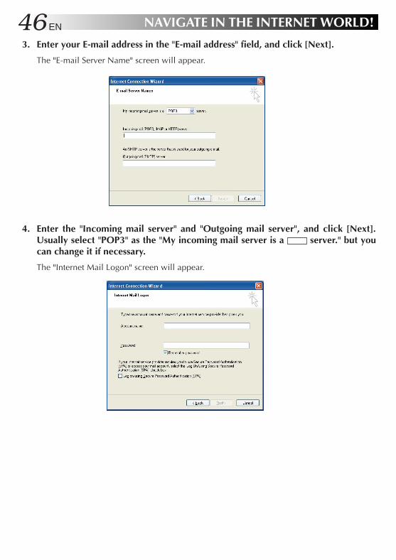
3. Enter your E-mail address in the "E-mail address" field, and click [Next].
The "E-mail Server Name" screen will appear.
4. Enter the "Incoming mail server" and "Outgoing mail server", and click [Next].Usually select "POP3" as the "My incoming mail server is a server." but youcan change it if necessary.
The "Internet Mail Logon" screen will appear.
XP72305230E_34_51 2/21/3, 7:11 PM46

EN 475. Enter the "Account name" and "Password," and click [Next].
The "Congratulations" screen will appear.
6. Click [Finish].
The "Congratulations" screen will close, and Outlook Express will start up.The setup for the E-mail software is complete.
7. To quit Outlook Express, click [x] at the upper right corner of the screen.
XP72305230E_34_51 2/21/3, 7:11 PM47

48 EN NAVIGATE IN THE INTERNET WORLD!
Sending and Receiving E-mailsYou can create and send E-mail messages, and receive and read E-mail from others. You canlearn procedures to enjoy E-mailing. Use Outlook Express installed on your PC for E-mailtransmission.
1. Click [start] and click [E-mail] on the Menu.
Outlook Express will start.
2. Click [Create a new Mail message] on the screen or click [Create Mail] in thetoolbar.
The "New Message" screen will appear.
Tips
To minimize the access fee to the provider and the use of the telephone line, create your E-mail messages before connecting to the Internet.
Disconnect from the provider.Connect to the provider.
(Create a responsereturnE-mail message)
Transmission
Create Read
XP72305230E_34_51 2/21/3, 7:11 PM48

EN 493. Create a message.
Destination: Enter the receiver's E-mail address. (Enter your E-mail address first to testE-mail transmission.)
Title: Enter the message title.
4. Click [Send] at the left upper end of the screen to send the created message.
The "Dial-up Connection" screen will appear.
Tips
If you have already connected to the Internet, the "Dial-up Connection" screen is not displayedbut the message is directly sent when you click [Send].
5. Click [Connect] in the "Dial-up Connection" screen to connect to the Internet.
You will be connected to the Internet, and the created mail will be sent to the specifiedaddress.
6. If your mail transmission is successful, try to receive E-mail. When you are connectedto the Internet, click [Send/Recv] at the left upper end of the screen.
Your PC will be connected to the provider’s mail server and you can receive E-mail.Assuming you have set your E-mail address correctly in Step 3, you can now receive the testE-mail you have sent to yourself.Tips
If message "You are currently working offline. Would you like to go online now?" appearswhen you have clicked [Send] or [Send/Recv], respond with [Yes].
Enter the E-mail address
Enter the message title
Enter the message text here
XP72305230E_34_51 2/21/3, 7:11 PM49

50 EN NAVIGATE IN THE INTERNET WORLD!7. To check the received messages, click [Inbox] on the screen.
The received E-mail messages will be displayed.
8. To quit Outlook Express, click [x] at the upper right corner of the screen.
Caution• Disconnect your PC from the Internet after you have transmitted E-mail and finished
accessing a Web site.
• It may not be possible to send mail properly using a company network or roamingservice. If this problem arises, the method below may solve it.Before sending the mail, first perform the receive mail operation even if no mail hasbeen received, and then click [Send].
XP72305230E_34_51 2/21/3, 7:11 PM50

EN 51
HARDWARE
4
XP72305230E_34_51 2/21/3, 7:11 PM51

52 EN
Using the Pointing DeviceThe pointing devices allow you to move the mouse pointer on the screen. You can move thecursor using the centre stick and three buttons in the similar way as the mouse.
¡ Stick operations
Usually operate the stick using your index finger. The mouse pointer moves in the directionyou press the stick. You can adjust the pointer moving speed by controlling the power topress. You can control the speed of mouse pointer movement by changing the pressure to thestick.
When you press the stick harder, the mouse pointer moves more quickly.
Notes
• If you press the stick slightly and move the pointer slowly for several seconds, the pointermay return backward. This is not a fault.
• Two stick caps are included in the PC accessory pack. When the cap has deteriorated,replace it with a new one.
¡ How to press the buttons
Usually press the three buttons using your thumb.
• ClickPress the mouse left button once and release it immediately.Use this operation to select a menu option or to press the [OK] or [Cancel] button.
• Right clickPress the mouse right button once.Use this operation to display a popup menu (called the shortcut).
Mouse pointer
Left button
Scroll button
Right buttonStick
HARDWARE
XP72305230E_52_65 2/21/3, 7:12 PM52

EN 53• Double-click
Press the mouse left button twice in succession and release it immediately.• Drag
Use this operation to move an icon or a file. To do so, select an icon or a file, hold down themouse left button and move it to the desired position, and release the mouse button.
Notes
The pointing devices have initially been set for the "right-handed person" on the "Mouseproperties" tab.
• Scroll buttonsYou can scroll the screen in the desired direction by holding down the scroll button andmoving the stick horizontally or vertically.
Notes
Some applications may not support the scroll buttons.
XP72305230E_52_65 2/21/3, 7:12 PM53

54 EN HARDWARE
Using Hot keys
You can use the coloured hot keys of the PC keyboard. Hold down the Fn key and press one ofthe Hot keys to execute its command.List of hot keys F1 Reduces the screen brightness level. Use this command to reduce the brightness level if
the screen is too bright. F2 Increases the screen brightness level. Use this command to increase the brightness level
if the screen is too dark. F3 Stand by the Mobile PC. F4 Hibernate the Mobile PC. F5 Reduces the volume. F6 Increases the volume. F7 Turns the PC speaker on or off. F9 Sets the wireless LAN to ON or OFF (XP-7230GB only).
(Refer to “Network connections using a wireless LAN” on pages 67 and 68.) F10 Switches between the LCD display and an external monitor. (Mode switching from LCD
panel to LCD plus CRT display, to CRT display) F11 Turns the Num Lock key on or off. For operation details, see "Using the Numeric Keypad"
of the next section. F12 Turns the Scroll Lock key on or off. Ins Issues the Print Screen (PrtSc) command. The screens displayed in the Windows are
copied onto the clipboard. You can select a window and copy it using the Alt keytogether.
Note• The hot keys are not supported in the MS-DOS environment.• If a key top has come off, refer to page 55.
Using the Numeric Keypad
Sixteen keys of the keyboard have been assigned to the numeric keypad. Each of these keys hastwo labels in different colours to identify their functions. (Blue characters printed on the diagonalpart of the key are numeric keypad keys.)
To use the numeric keypad:Hold down the Fn key and press the NumLK key. When the numeric keypad is functional, theNum Lock lamp lights. (See the "Status Indicators" on Page 19. Now, you can enter a numeralprinted in blue on the diagonal part of the key.
XP72305230E_52_65 2/21/3, 7:12 PM54

EN 55If a key top has come off
If a key top has come off from the keyboard, put it back in place by following the procedurebelow.
¡ How to attach the Enter key, left Shift key or Space key top1 Take out the disengaged wire rod, and snag it onto the two projections as shown in the
figure below.2 Place the disengaged rubber cushion at the position shown in the figure below.3 Align the center position of the key top with the center position of the rubber cushion, and
press the key top down until it clicks into place.4 Operate the key with its key top now in place as you would operate it normally, and check
that it does not come off.
¡ How to attach any other key topThe wire rod shown above is provided with Enter key, left Shift key and Space key only. Whenthe key top of any other key has come off, follow steps 2 to 4 above.
Note• As soon as the key top clicks into place in step 3 of the procedure to attach the key top, donot apply any further pressure to it or the key may be damaged.
S N b V
b h
L [ g b vª ' u J ‘ b v„ “ • Ø ¯
Rubber cushion
Wire rod
key topPress down until itclicks into place.
XP72305230E_52_65 2/21/3, 7:12 PM55

56 EN
Increasing the (Optional) Memory CapacityYou can increase the PC memory capacity up to 384M bytes. For the built-in memory capacity,see the Product Specifications on Page 102. You can reduce the application startup time andincrease the data process speed by adding an optional memory board.
Consult the JVC PC Technical Support Centre listed at the end of this manual for memoryexpansion.
Notes
¡Check the memories supported by your PC by accessing:http://www.jvc.co.ukThe memory boards which have been checked for reliable operations are listed on ourWeb site. Any other memory board may not be recognized by your PC or its operationmay be unreliable.
¡The PC inside contains precision components. If you have damaged the memory board byadding a memory, it is not covered by the warranty. Also, if you have damaged your PC,you will be charged for its repair.
¡Take care not to cause excessive static electricity. Do not add a memory board in a placewhere static electricity may be generated.
¡When you add or replace a memory board, take care not to drop water or other liquidsonto your PC or the memory board. Also, take care not to drop screws or other foreignmaterials that may cause the failure of your PC.
¡Data stored in the PC may be corrupted or damaged in the following cases.
• The battery is used incorrectly.• The PC is affected by static electricity or electrical noise.• The battery has discharged.• The PC is faulty or under repair.• The PC is dropped or exposed to severe impact.• The PC is involved in force majeure including lightning or power failure.
HARDWARE
XP72305230E_52_65 2/21/3, 7:12 PM56

EN 57 Adding or Removing a Memory Board
If you have operated your PC, its inside may be hot and you may get a burn. Turn the powerswitch off and wait for the PC to cool down.
1. Turn the PC Power switch off, and disconnect AC adapter from your PC. Then,remove the standard lithium ion battery pack (if any) and all other peripheralsfrom your PC.
2. Remove the built-in lithium ion battery pack and the memory expansion cover bytaking the following steps.1) Turn your PC upside down, and remove screws 1 to 4.2) Remove the built-in lithium ion battery pack.3) Open the memory expansion cover.
1)
3)Remove the batterypack by sliding itin this direction.
2)
Cautions• Screw 1 (10 mm) is different in length from screws 2 to 4 (3 mm). Using a wrong screw can
damage your PC.• Do not loosen any other screws, otherwise, your PC may fail.
3. Discharge any static electricity from your body by touching something metallicnearby.(Not on the PC)
4. Add or remove a memory board.
CautionsThe MP-XP7230GB PC already has 128M-byte memory in its memory slot. You need toreplace it with a 256M-byte memory board to expand the PC memory capacity to the maximum384M bytes. To do so, remove the 128M-byte memory board from the slot. See Procedure“2) Remove the memory board” on Page 58.
XP72305230E_52_65 2/21/3, 7:12 PM57

58 EN
1) Mounting a memory board1 Check the correct mounting direction of memory board (by observing the cut area).2 Slant the memory board and insert it into its socket.3 Push the memory board until it is locked, but do not apply excessive force to it.
CautionsIf it is difficult to lock the memory board, make sure that the board has been inserted securely.Do not apply excessive force to it, or the memory board may be damaged.
2) Removing the memory board1 Open the right and left support levers of the memory board by pressing them outward.2 Pull out the memory board in the arrow direction.
5. Return the memory expansion cover, mount the battery pack, and retighten thefour screws.
CautionThe screws have different lengths. Be careful to use the right screw in the right place.
Cut area of memory board
Memory slot
Memory board
Memory slot
Memory board
HARDWARE
XP72305230E_52_65 2/21/3, 7:12 PM58

EN 59 Checking the Additional Memory Board
Use the following procedure to check the memory board installation.
1. Turn on your PC and start Windows.
2. Click [start] and select [Control Panel].
3. Click the [Performance and Maintenance] icon.
4. Click the [System] icon.The "System Properties" screen will appear.
5. The total amount of memory appears on the screen.• 368 MB RAM appears when 384 MB (128 MB + 256 MB) of memory is installed.• 240 MB RAM appears when 256 MB (128 MB + 128 MB) of memory is installed.
NoteThe size of the video memory (assigned size) was set to 16MB prior to shipment from thefactory.
Checking here
XP72305230E_52_65 2/21/3, 7:12 PM59

60 EN
Using the SD Memory Card SlotYour PC has an SD memory card slot.An SD memory card or multimedia card can be used.When you use an SD memory card, remove the dummy card from the SD memory card slot.
1. Remove the dummy card.
2. Insert an SD memory card.
Caution: Insert the SD card in the correct direction.
Notes
• The SD memory card and multimedia card are optional.
• The SD memory card slot of your PC does not support the SD I/O function and datatransfer using the copyright protection functions.
• If you do not use an SD memory card on your PC, keep the dummy card inserted in theslot to prevent dust or other foreign bodies getting into the PC.
• When formatting an SD memory card or MultiMedia card in this PC’s SD memory cardslot for use in a DVC or digital camera, first select [FAT] rather than [FAT32] on the WindowsXP format screen, and then proceed with the formatting.
* Before formatting a memory card, back up its contents on the PC’s hard disk drive, forinstance.
1 Press the dummy card slightly, and it will be ejected.2 Hold the ejected card and remove it from your PC.
12
Check the cut area.(The terminal sidemust face downward.)
HARDWARE
XP72305230E_52_65 2/21/3, 7:12 PM60

EN 61Using an External MonitorTo attach an external monitor to your PC, use the MP-VGX1E external display cable.
Connecting an external monitor
When you connect an external monitor to your PC, it looks like an ordinary desktop PC. Youcan use the monitor by just connecting it with the MP-VGX1E cable. You can display images onthe external monitor for other people and you can watch them on the LCD panel of your PC.
For display switching between the external monitor and the LCD panel of your PC, see "Usingthe hot keys" on Page 54.
Note
• To disconnect the external display connecting cable (MP-VGX1E), be absolutely sure to pullit straight out while pressing the PUSH button at the same time.
Face the PUSH buttondownward.
XP72305230E_52_65 2/21/3, 7:12 PM61

62 EN
• The display max resolution you can set for the external monitor is 1600 x 1200 x 32 bits,which depends on monitor performance.
• When the display resolution is set to 1024 x 600 x 32-bit colours, enabling the simultaneousdisplay of internal and external monitors automatically changes the number of display coloursto 16-bit colour display. If you then select the separate display of internal and external monitors,the number of colours is not automatically changed. Thus, to enable the 32-bit colour display,you must re-define the number of colours with the Display Properties dialog box.
• Caution when the expansion display with a resolution of 800 x 600 is disabled. (shipmentsetting: enabled)Since the mirror mode (screens displayed by the LCD and external display unit) is set afterstartup when the power is turned on with the PC connected to the external display, use thehot key ( Fn + F10 : see page 54) to select the display again in line with the mode that willbe used.
* How to enable and disable the expansion display with an LCD resolution of 800 x 6001) Press the Alt + F2 keys when the system starts up (when the JVC logo is displayed).2) The “Award BIOS Setup Utility” screen will appear. Select [Advanced] using the → cursor
key.3) Select “LCD Expansion” using the ↓ cursor key and press Enter . Then select [Enabled] or
[Disabled] using the ↓ cursor key, and press Enter .4) Next, press the F10 key. “Setup confirmation” will appear so select [Yes], and press Enter .
(If you are not thoroughly familiar with PCs, do not change the BIOS settings. Selecting thewrong settings may not only make it impossible for the PC to start up but it may even causemalfunctioning.)
HARDWARE
XP72305230E_52_65 2/21/3, 7:12 PM62

EN 63Connecting to a networkWith the network function, you can connect to a network at your office or home to transfer databetween PCs and access the Internet from multiple PCs. For setting for intranet connection,consult a system administrator at your company. Connection to a network requires the followingitems.
• LAN cable• Communication devices including a hub or router
Important
LAN cables are available in straight and cross types. Use a cable of the correct type for yourLAN environment.
You must contract with an Internet service provider.
Using a LAN cable, connect the LAN connector on the unit with a communication device (hubor router).See the following for setting.
Setting for network connection
¡Setting the IP address manually
Important
This PC will acquire the necessary initial settings automatically. When you use this PC ina home network environment and the IP address is assigned automatically, the followingsteps are not necessary.1 Click the [start] button and [Control Panel].2 Click the [Network and Internet Connections] icon.3 Click the [Network Connections] icon.
The “Network Connections” screen will appear.
XP72305230E_52_65 2/21/3, 7:12 PM63

64 EN
4 Double-click [Local Area Connection].The “Local Area Connection Status” screen will appear.
5 Click the [Properties] button.The “Local Area Connection Properties” screen will appear.
6 On the [General] tab, double-click [Internet Protocol (TCP/IP)].The “Properties of Internet Protocol (TCP/IP)” screen will appear.
7 Enter appropriate values in the [Use the following IP address] and [Use the followingDNS server addresses] fields.
8 Click the [OK] button to save the setting.
¡Setting a computer name or work group
Tips
To share data or a printer among a group of computers, you must set the computers in thesame work group. This enables you to transfer data between computers.1 Click the [start] button and [Control Panel].2 Click the [Performance and Maintenance] icon.3 Click the [System] icon.
The “System Properties” screen will appear.4 Click the [Computer Name] tab.5 Click the [Change] button.6 Change the “Computer name”and/or “workgroup” as necessary.7 Click the [OK] button to save the setting.
The “Change in computer name” screen containing the “Welcome to the ***workgroup.” message will appear.
HARDWARE
XP72305230E_52_65 2/21/3, 7:12 PM64

EN 658 Click the [OK] button.
A message prompting you to restart the computer will appear.9 Click the [OK] button to make the change take effect.0 Restart the computer.
¡Checking the MAC address
Use the following procedure to check the MAC address of the internal LAN card.
Important
To check the MAC address, you have to set a LAN (local area) connection in the [Networkconnection] screen.
1 Click the [start] button and [Control Panel].2 Click the [Network and Internet Connections] icon.3 Click the [Network Connections] icon.
With the correct LAN connection, the following screen will appear.
4 Check that [Local Area Connection] is enabled.
Tips
it is disabled, move the mouse pointer to [Local Area Connection] and press the rightmouse button to bring up a menu, click [Enable] to enable the connection.
XP72305230E_52_65 2/21/3, 7:12 PM65

66 EN
5 Double-click [Local Area Connection].The “Local Area Connection Status” screen will appear.
6 Click the [Support] tab and the [Details] button.The “Network Connection Details” screen will appear.
7 The MAC address is displayed as the “Physical Address” on the list.
HARDWARE
XP72305230E_66-81 2/25/3, 5:44 PM66

EN 67Network connections using a wireless LAN (MP-XP7230GB only)The model MP-XP7230GB PC comes with wireless LAN functions. (The MP-XP5230GB seriesdoes not come with these functions, and the details provided in “Network connections using awireless LAN” do not apply.)You can connect to a LAN system from any location within the wireless communication area toaccess the Internal LAN or send and receive mail. By using a wireless LAN access point (availablefrom a retail store) which is connected to an ADSL modem (available from a retail store), youcan access broadband environments from a multiple number of PCs. Furthermore, you canbring your PC to one of the public wireless LAN services which have been increasing of late andenjoy accessing the Internet by wireless means.For the wireless network settings and details, refer to [Help and Support] on the [Start] menu.
General description of wireless LAN
The wireless LAN in this PC supports the following functions.• Automatic communication speed selection function:11, 5.5, 2 and 1 (Mbps)• Frequency channel selection : All 13 channels (2412 to 2472 MHz)• Roaming between multi-channels• Power management function• Compliance with IEEE802.11 and IEEE802.11b standards
Types of wireless LAN networks
• AdHoc ModeIn this mode, the data is transferred directly between PCs. It is suited to wireless networks inwhich data is transferred between several laptops. The peer-to-peer workgroup setting forproviding equal handling for all the laptops is established.
• Infrastructure ModeIn this mode, the PCs are connected through an access point. If the access point is connectedto an ADSL, CATV, ISDN or other such line, the PCs can be connected to the Internet as well.
XP72305230E_66-81 2/25/3, 5:44 PM67

68 EN HARDWARE
Suggestions for using the wireless LAN
• Use the wireless LAN in a location where there are as few obstacles as possible. To maximizethe distance over which communication with the wireless LAN is possible, open the display,and point its reverse side (the side with JVC logo) at the access point. Do not place anyobstacles such as books or thick stacks of paper between the PC and access point.
Setup procedure for the wireless LAN
CautionIn order to make it easier to check the operation of the PC’s wireless LAN, start the access pointbefore proceeding to use the wireless LAN in the infrastructure mode. For use in the AdHocmode, start the PC that serves as the other end of the communication where the wireless LANsettings have already been completed if possible before proceeding to use the wireless LAN inthis mode.
Wireless LAN antenna
Wireless LAN antenna
XP72305230E_66-81 2/25/3, 5:44 PM68

EN 691 Start up the PC.
2 Set the IP address to be used by the wireless LAN.1 Click [Start], and select [Show all connections] from [Connect To] on the start menu.
2 Select [Wireless Network Connection] on the [Network Connections] screen, and select[Properties] on the [File menu].
XP72305230E_66-81 2/25/3, 5:45 PM69

70 EN HARDWARE3 Select [Internet Protocol (TCP/IP)] on the [General] screen of [Wireless Network Connection
Properties].
4 The [Internet Protocol (TCP/IP) Properties] screen appears.
5 Use the following example as a reference, and proceed with the settings depending onhow the wireless LAN is to be used.
XP72305230E_66-81 2/25/3, 5:45 PM70

EN 71For making the wireless network connection using a public wireless LAN service :With a public wireless LAN service, it is customary for the DHCP server function thatautomatically allocates the IP address to be enabled. On the “Internet Protocol (TCP/IP)Properties” screen, click and select “Obtain an IP address automatically” and “ObtainDNS server automatically” , and click the [OK] button.
For directly communicating with another PC using a peer-to-peer connection :Set the IP address which has the same network address as the IP address of the PC thatserves as the other end of the communication. If, for example, the IP address at the otherend is 192.168.1.1, click and select “Use the following IP address” on the “Internet Protocol(TCP/IP)” screen, and input 192.168.1.2, for instance, in the “IP address” field. Input255.255.255.0 for “Subnet mask,” and click the [OK] button.
For making the wireless network connection via an access pointIn cases involving an in-company LAN, etc. where a DHCP server is in operation on thewired network to which the access point is connected, click and select “Obtain an IPadress automatically”and “Obtain DNS server automatically” on the “Internet Protocol(TCP/IP) Properties” screen, and click the [OK] button. (Check with a network administratorto ascertain whether the DHCP server is in operation.)In a home or other such environment where a DHCP server is not in operation, manuallyset the IP address to the one that has the same network address as the IP address of theaccess point. If, for example, the IP address of the access point has been set to 192.168.10.1,click and select “Use the following IP address” on the PC’s “Internet Protocol (TCP/IP)”screen, and input 192.168.10.2, for instance, in the “IP address“ field. Input 255.255.255.0for “Subnet mask,” and click the [OK] button.When connecting to the Internet using a wireless LAN access point connected to an ADSLmodem (available from a retail store), check the method used to set the IP address withthe Internet service provider.
3 Press the Fn and F9 keys at the same time to turn on the wireless LAN.The wireless LAN starts, and the wireless LAN start icon appears at the top left of the display.
The wireless LAN indicator above the F10 key flashes while a search is being conducted,and it stops flashing and remains lighted once the connection is made.
NoteAt the time of shipment, the wireless LAN is set to ON. The previous settings will apply whenthe PC is started up or when its operation is resumed from the standby or hibernation mode.In order to prevent other electronic devices in places such as aircraft and hospitals from beingadversely affected, set the wireless LAN to OFF and close down its functions using the hotkeys (pressing the Fn and F9 keys at the same time) if it is possible for the PC to be used inplaces like these.
XP72305230E_66-81 2/25/3, 5:45 PM71

72 EN HARDWAREWhen the wireless LAN status icon is clicked on the task tray, the main menu of the wirelessLAN setting utility is opened, enabling the wireless LAN status to be checked or set.
The color of the wireless LAN status icon indicates the connection status and signal strengthstatus.Green on a white ground: Now connected (signal strength: strong)Yellow on a white ground: Now connected (signal strength: weak)Red on a white ground: Now searching the base stationRed cross on a white ground: Wireless LAN in the OFF statusRed cross on a green ground: Now connected (an error has occurred); the wireless network
cannot be used. Re-check the encryption (page 74).
4 Perform the wireless network settings.1 Status
Wireless LAN connection status display and wireless LAN ON/OFF switchThe connection status, current transmission rate (Mbps) communication channel,throughput (bps), link quality and signal strength are displayed.
When [Rescan] is clicked, the connection destination is searched again.When [Disable Radio] is clicked while connected, the wireless LAN function is set toOFF.When [Disable Radio] is clicked while the wireless LAN is OFF, the wireless LAN functionis set to ON, the connection destination is searched, and the connection is established.The wireless LAN can also be set to ON or OFF by pressing the hot keys ( Fn + F9 ).
NoteIn the case of a peer-to-peer network type, the link quality and signal strength are notdisplayed.
XP72305230E_66-81 2/25/3, 5:45 PM72

EN 732 Settings
Perform the wireless LAN communication settings.
This utility can retain multiple sets of setting information, and these sets can be selectedfor use. The settings are each managed by a [Profile]. When new settings are to beadded, input the profile name of your choice, and then proceed with the settings.
[SSID]Perform the ESS-ID setting for the network name. The wireless LAN group can be createdby setting the ESS-ID. When it has been set, communication is possible only with theconnection destination for which the same ID has been set.[Mode]Select either access point (infrastructure mode) or peer-to-peer (AdHoc mode) as thenetwork type to be used.For details on each of these network types, refer to the unit’s instruction manual (page 78).NotesWhen constructing a peer-to-peer network, select the channel number to be used using[AdHoc Channel].[Power Save Mode]Select On, Off or Auto as the power-saving mode setting.[Transmit Rate]1Mb: The transmission rate is fixed at 1 Mbps.2Mb: The transmission rate is fixed at 2 Mbps.Auto 1 or 2Mb: The transmission rate is automatically selected from 1 Mbps or 2 Mbps.5.5Mb: The transmission rate is fixed at 5.5 Mbps.11Mb: The transmission rate is fixed at 11 Mbps.All auto: The transmission rate is automatically selected.
When [OK] or [Apply] is clicked, the settings are saved or changed.
XP72305230E_66-81 2/25/3, 5:45 PM73

74 EN HARDWARE3 Encryption
Perform the encryption (WEP security) settings for communication.
The WEP function encrypts key words and scrambles them in the transmission data. Anetwork using a high level of security can be configured when it is activated. While thefunction is activated, the same WEP keys must be used by all the computers in the group.Set the WEP keys by following the steps below.
[Encryption (WEP security)]As the WEP function setting, select “64 bit,” “128 bit” or “Not Used.”As the WEP key input method, select [Create Keys Manually] or [Create Keys withPassphrase].[Create Keys Manually]• Alphanumerics: 5 or 13 characters
Select this setting to designate the WEP keys using specific alphanumerics.Set 5-character keys with the 64-bit WEP function setting and 13-character keys withthe 128-bit WEP function setting.
• Hexadecimal: 10 or 26 charactersSelect this setting to designate the WEP keys using hexadecimal notation (0-9, A-F).Set 10-character keys with the 64-bit WEP function setting and 26-character keys withthe 128-bit WEP function setting.
• Key 1 to key 4Input the WEP keys. Input the prescribed number of characters as alphanumerics or ahexadecimal character string. Up to four WEP keys can be registered. Designate theregistered WEP keys (1 to 4) using [Use WEP Key].
[Create Keys with Passphrase]This input method is used when generating the WEP keys (key 1 to key 4) using a password.
When [OK] or [Apply] is clicked, the settings are saved or changed.
XP72305230E_66-81 2/25/3, 5:45 PM74

EN 754 About
The software version information and MAC address of the wireless LAN mode are displayed.
[Network Driver]The network driver version information is displayed.[Configuration Utility]The configuration utility version information is displayed.[NIC Firmware]The version information and MAC address of the wireless LAN module’s firmware aredisplayed.
5 When the PC is connected to the wireless network, the following message appearson the task tray:
How to shut down the wireless LAN functions
Follow the steps below to shut down the wireless LAN functions.
1 Press the Fn and F9 keys at the same time.
2 The wireless LAN shutdown icon will appear on the display, and the wireless LANindicator above the F10 key will go off.
• In order to conserve power, it is recommended that the wireless LAN functions be shut downwhen they are not in use.
XP72305230E_66-81 2/25/3, 5:45 PM75

76 EN
Checking the battery levelOn the “Power Option Properties” screen, click the [Power Meter] tab. The current total batterylevel is displayed. Use the following procedure.
1. Click the [start] button and [Control Panel].
2. Click the [Performance and Maintenance] icon.
3. Click the [Power Options] icon.The [Power Option Properties] screen will appear.
4. Click the [Power Meter] tab.
Battery gauges #1 (built-in battery) and #2 (external battery), and the total level of these twobatteries are displayed.
Important• Battery gauge #2 (external battery) is displayed only when a standard lithium ion battery
pack or large-capacity lithium ion battery pack is used.• Note that the external battery is consumed first.
HARDWARE
XP72305230E_66-81 2/25/3, 5:45 PM76

EN 77Power-saving modeIn compliance with the operation regulations of the International Energy Star Program, this unitenters the power-saving mode when no operation is performed for a certain period.
On the [Power Schemes] tab in the “Power Option Properties” screen (page 76), you can specifythe time that must expire before the unit enters the power-saving mode. The table below showsthe factory settings.
Operating onAC power Status
1 Turn off monitor: 15 minutes 5 minutes
2 Turn off hard disks: 30 minutes 5 minutes
3 System standby: 20 minutes 5 minutes
4 System hibernates: 3 hours 2 hours
The LCD screen turns off.The (Stand By) lamp is still lit in green.
The hard disk power is turned off withthe LCD screen kept off. The (Stand By) lamp is still lit in green.
The PC stores the current system statuson the hard disk. The (Stand By) lampwill go out.
The LCD screen is turned off.The (Stand By) lamp flashes in green.
Tips
To exit status 1 or 2 , move the stick or press any key on the keyboard.To exit status 3 , press the Power key or any key on the keyboard.To exit status 4 , press the Power key.
Important
• In statuses 1 through 3, Windows is still running. Note that the current condition islost if the PC is turned off by pressing the Power key for more than 4 seconds.
Operatingon battery
XP72305230E_66-81 2/25/3, 5:45 PM77

78 EN
• System in standby status
The built-in battery discharges whilst the PC is in system standby status. As a result,any unsaved data may be lost or the system may not start up. Be sure to turn off the PCwhen it is not used for a long time.Under fully charged condition, the unit can maintain the system standby status for thefollowing periods.1 About 20 hours with the built-in battery pack alone2 About 55 hours with the built-in and standard battery packs
• System in halt status
Continued operation on the PC displaying a battery-low warning causes the result asfollows:1 When the halt status is enabled
The PC turns off while maintaining the current data.2 When the halt status is disabled
The PC does not save the current data, which will be lost.
We recommend that you enable the halt status setting. This function is enabled at thefactory.
HARDWARE
XP72305230E_66-81 2/25/3, 5:45 PM78

EN 79Unknown partition on hard disk
IMPORTANT!!
This PC reserves the image data required for recovery as a “recovery area” in the hard disk. If youaccidentally delete a partition of the recovery area, you cannot recover it. The important points tokeep in mind are:
• DO NOT attempt to delete a hard disk area shown as an “Unknown partition” using theWindows XP “Administrative Tools”, or to assign it as another drive name.
• DO NOT attempt to delete the recovery area using specific software available in the market byinitializing or changing any partition in the hard disk.
Should you delete the recovery area and ask us to re-setup your PC, you will be liable for the cost.
XP72305230E_66-81 2/25/3, 5:45 PM79

XP72305230E_66-81 2/25/3, 5:45 PM80

PC RECOVERY(REPEATED PC SETUP)
5
XP72305230E_66-81 2/25/3, 5:45 PM81
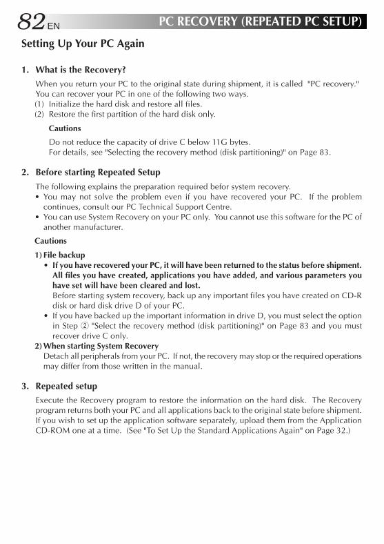
82 EN PC RECOVERY (REPEATED PC SETUP)
Setting Up Your PC Again
1. What is the Recovery?
When you return your PC to the original state during shipment, it is called "PC recovery."You can recover your PC in one of the following two ways.(1) Initialize the hard disk and restore all files.(2) Restore the first partition of the hard disk only.
Cautions
Do not reduce the capacity of drive C below 11G bytes.For details, see "Selecting the recovery method (disk partitioning)" on Page 83.
2. Before starting Repeated Setup
The following explains the preparation required befor system recovery.• You may not solve the problem even if you have recovered your PC. If the problem
continues, consult our PC Technical Support Centre.• You can use System Recovery on your PC only. You cannot use this software for the PC of
another manufacturer.
Cautions
1) File backup• If you have recovered your PC, it will have been returned to the status before shipment.
All files you have created, applications you have added, and various parameters youhave set will have been cleared and lost.Before starting system recovery, back up any important files you have created on CD-Rdisk or hard disk drive D of your PC.
• If you have backed up the important information in drive D, you must select the optionin Step 2 "Select the recovery method (disk partitioning)" on Page 83 and you mustrecover drive C only.
2) When starting System RecoveryDetach all peripherals from your PC. If not, the recovery may stop or the required operationsmay differ from those written in the manual.
3. Repeated setup
Execute the Recovery program to restore the information on the hard disk. The Recoveryprogram returns both your PC and all applications back to the original state before shipment.If you wish to set up the application software separately, upload them from the ApplicationCD-ROM one at a time. (See "To Set Up the Standard Applications Again" on Page 32.)
XP72305230E-82-104 2/26/3, 8:57 AM82

EN 83System Recovery Procedure
1. Hold down the Alt and F8 keys and press the Power button to start up your PC.When message "Do you wish to continue? (Y/N)" appears, respond with Y.
Tips
• If you respond with N, the recovery is canceled. The PC will restart and the Windows OSwill start up.
• If too much time is taken to press the key or a continuous beep is heard for other reasons,turn off the power, and repeat the process.
• If Windows starts up after a delay, exit Windows, turn off the power, and repeat the process.
2. Read the License Agreement when displayed.If you accept the Agreement, type Y.
Tips
If you respond with N, the recovery is canceled. The PC will restart and the Windows OSwill start up.
3. Select the recovery method (disk partitioning).When message "Select the recovery method (A (Recommended)/C)" appears, respond withthe 1 or 2 key as follows.1 If you respond with A:
All disk partitions and files of the hard disk are recovered, and the entire PC system isinitialized to its original state.
2 If you respond with C:The files of drive C are recovered and initialized.(Usually, all data of drive D remains unaltered, as they are, and only the data of drive Cis initialized. If drive D has already been removed, the PC only has drive C.)
4. The system recovery starts, and its progress is shown on the screen.
XP72305230E-82-104 2/26/3, 8:57 AM83

84 EN COMPUTER WIEDERHERSTELLUNG (RECOVERY)
5. After the system recovery has been completed, the message "Turn Power switch offand restart the PC." appears. Restart your PC.Your PC has been returned to the original state before shipment.
6. Set up the Windows OS by following the "Initial Setup of Microsoft Windows"procedure on Page 20.
XP72305230E-82-104 2/26/3, 8:57 AM84

EN 85
TROUBLESHOOTING
6
XP72305230E-82-104 2/26/3, 8:57 AM85

86 EN
Q&AThere are several troubleshooting keys. If you are not sure how to operate your PC, your PC doesnot work well, or you suspect that your PC has been damaged, follow the relevant troubleshootingsteps in the Q&A section.
If the Q&A does not help you
Contact us.
If you cannot remove the trouble successfully, contact the JVC PC Technical Support Centre.See the back cover for the phone number.
Power
Q. The power does not turn on.
A. Check the following.
¡ Check that the Power key is pressed.Press the (On/Off) key to turn on your PC. See “Turning (On/Off) key On” on page19.
When you are using your PC on AC power ¡ Check that the AC adapter is connected.
For connection, see “4. Recharge the built-in battery pack by plugging the AC cord into DCInput connector” on page 17.
When you are using your PC on the battery ¡ Check that the battery is fully charged.
For how to charge the battery, see “5. Make sure that the battery pack is fully charged” onpage 18.
TROUBLESHOOTING
XP72305230E-82-104 2/26/3, 8:57 AM86

EN 87Startup and Operation of Windows
Q. The screen has hung.
A. Use the following procedure to forcibly exit the applications running on your PC.
ImportantWhen applications are forcibly terminated through this procedure, any unsaved unsaveddata will be lost.
Terminating an application forcibly1. While holding down the [Ctrl] and [Alt] keys, press the [Del] key once.
The “Windows Task Manager” screen will appear.2. Click the [Applications] tab.3. Click the application that hung, then [End Task]. In most cases, applications that have
hung are indicated as “Not Responding.”4. When a confirmation message for terminating the application appears, click [End Now].5. Click [x] on the Windows Task Manager screen.
Tips
When the application cannot be terminated, forcibly restart Windows. To restart Windowsforcibly, start Windows Task Manager, click [Shut Down] on the toolbar, then click [Restart].If your PC does not restart through the above procedure, press the RESET button on theside of the unit (page 12) or keep pressing the Power key for 4 seconds or longer to turnoff the power.
About the message appearing if Windows is not exited normallyIf you turn off the power without terminating Windows, the “Checking file system on c:”message appears at the next Windows startup, Windows and hard disk conditions will bechecked, and data will be restored as necessary.
XP72305230E-82-104 2/26/3, 8:57 AM87

88 EN
Q. Starting the PC in the safe mode
A. If some kind of trouble occurs on the PC, use the safe mode where the PC starts up withminimum functions.Use the following procedure to start up your PC in the safe mode.1. Turn on the PC.2. As soon as the JVC logo appears, hold down the F8 key.
Tips
If the F8 key is pressed too late, Windows tries to make a normal startup.Restart your PC and go back to step 2.
3. Select [Safe Mode] and press Enter .4. Check that the operating system is selected on the “Please select the operating system to
start:” screen. Press Enter .5. When you see the “To begin, click your user name” message, click an account with
which you want to start the PC in the safe mode.6. Clicking [Yes] starts your PC in the safe mode.
TROUBLESHOOTING
Q. If Windows will not start
A. When “Power On Self Test” is carried out at the time of power on and something wrong orout of order is detected, an error code (2 digits) is indicated on the screen, and start-up issuspended.
If you think that Windows will not start confirm whether an error code is indicated on thescreen. When you ask for service, please report this error code to the service centre.
An error code may not always be indicated dependent on the cause of the trouble.
XP72305230E-82-104 2/26/3, 8:57 AM88

EN 89Display
Q. The PC is turned on but nothing appears on the screen.
A. If the screen blacks out during operation, check the following.
¡ When the (Stand By) lamp is lit.• Move the stick or press any key on the keyboard to check if the power-saving function is
working.
• Check if the display is configured as an external display device.[While pressing Fn , press F10 . (Each time you do this, you can change betweenexternal display and LCD modes.)
• To adjust the LCD display brightness:Pressing Fn and F1 turns the screen darker.Pressing Fn and F2 turns the screen brighter.
¡ When the (Stand By) lamp is flashing.The PC is in standby mode (The power-saving mode is working).Press the On/Off key or any key on the keyboard.ImportantPressing the (On/Off) key for more than 4 seconds terminates Windows forcibly, discardingthe unsaved data.
¡ When the (Stand By) lamp is not lit.The PC is turned off. Press the (On/Off) key to turn on your PC.
XP72305230E-82-104 2/26/3, 8:57 AM89

90 EN TROUBLESHOOTINGUsing the Internet
Q. I cannot dial up.
A. Check the connection.
¡ Check that the modem cable is connected.If you see the “There was no dial tone.” message, check the connection between the unitand the telephone line connector on the wall. Insert the modem fully until it is locked.
¡ When a divider is usedConnect the modem cable directly to the phone jack for checking.
¡ When you are connecting via an ISDN lineCheck that the terminal adapter is ready.For details, refer to the instruction manual for your terminal adapter.
¡ Check that the modem is recognized properly.1. Click the [start] button and [Control Panel].2. Click the [Printers and Other Hardware] icon.3. Click the [Phone and Modem Options] icon, then the [Modems] tab.4. Select the modem by clicking it, click [Properties], then the [Diagnostics] tab.5. Click [Query Modem].
When the modem is recognized properly, the inquiry command and response to it willbe displayed.
ImportantIf the modem is not recognized properly, check if it conflicts with any other device.If the modem device is displayed with a “!” mark on the Device Manager screen, it mayconflict with another device.
XP72305230E-82-104 2/26/3, 8:57 AM90

EN 91Q. The PC dials but connection is not established.
A. Check the dialing setting.
¡ Check that the dialing type (tone or pulse) is correctly set for your telephone line.For checking and configuration procedures, see “3. Setting up the modem” on page 36.
¡ When no connection operation occurs, check the destination setting.Use the following procedure to check the setting for connecting to your Internet ServiceProvider (ISP) or network.1. Click the [start] button and [Control Panel].2. Click the [Network and Internet Connections] icon.3. Click the [Network Connections] icon.4. Right-click the icon for the destination of connection to bring up a pop-up menu. Click
[Properties] in the menu.5. Check the setting according to the instruction manual provided from your ISP.
• On the [General] tab, check the “Connect using” and “Phone number” settings.
Tips
Some ISPs have different phone numbers for access points via ISDN lines from thosefor points via ordinary lines. Contact your ISP for details.
• For how to check and set the DNS server addresses (primary DNS and secondaryDNS), see DNS server address setting procedure (10-20) on pages 40 and 41.
ImportantIf your ISP specifies no DNS server address, click [Obtain DNS server address automatically].
XP72305230E-82-104 2/26/3, 8:57 AM91

92 EN
Q. The PC makes a connection operation but connection is not established.
A. Check the following.
¡ Check the user name and password.Refer to the material sent from your ISP for correct user name and password.
¡ The internal modem dials but negotiation is not made.The access point may have a problem. Try to establish a connection later. If this attemptfails, use a different access point.
¡ Advice when using the internal modemIf “Max Battery” or “Presentation” has been selected for “Power Options” in the “PowerOptions”/”Power Schemes” tab from [Power Option Properties] and the battery is beingused to power the PC, this may cause the internal modem to slow down its speed ofcommunication or fail to dial up, depending on the condition of the telephone line. Incases like this, change to a setting other than “Max Battery” or “Presentation” (such as“Portable/Laptop”).
Q. The PC cannot send or receive e-mail messages.
A. If you are using the Outlook Express software, check the e-mail software settings.
If you are using any other mailer than Outlook Express, refer to the pertinent instructionmanual or help.1. Start Outlook Express.
Tips
If the “Dial-up Connection” screen appears, click [Work Offline] or the [x] button.
2. Click [Tools] on the tool bar (at the top of the screen). Click [Accounts] on the Toolsmenu.
3. Click the [Mail] tab.4. Click an account and [Properties].5. Click the tabs to check that the entries are correct.
ImportantUse lower-case letters only.
TROUBLESHOOTING
XP72305230E-82-104 2/26/3, 8:57 AM92

EN 93Wireless LAN (MP-XP7230GB only)
Q. I can’t communicate.
A. Check the following.
¡ Is the device serving as the other end of the communication the kind of device which cancommunicate with the PC?A number of communication systems can be used with the wireless LAN, but unless thesame system is used at both ends, communication will not be possible.
¡ Has the security been set correctly?Select the same setting for the network key (WEP encryption) of this PC’s wireless LAN asthe one used by the access point.
¡ Has the IP address been set correctly?Check whether the IP address been set correctly by taking step 2 (Set the IP address usedwith the wireless LAN) on page 69 in the section entitled “Network connections using awireless LAN.”
¡ If the wireless LAN cannot be set to ON or OFFWhen the PC has been re-started after termination caused by an error, the wireless LAN mayremain inoperable. In a case like this, shut down the PC and then start it up again.
Q. The communication speed is slow.
A. Check the distance between the PC and the other end of the communication. In somecases, the communication speed varies depending on the distance involved.
Q. I can’t share with other computers on the network.
A. If no other computers appear on “Local Network” selected from “My Network Places,”establish the same “Workgroup” or “Domain” setting.
XP72305230E-82-104 2/26/3, 8:57 AM93

94 EN
Q. How can I check the MAC address?
A. Proceed as follows to check the MAC address of the PC’s wireless LAN.* In order to check the MAC address, the wireless network connection must first be set
using [Network Connections].1. Click the [Start] menu, and click [Control Panel].2. Click the [Network and Internet Connections] icon.3. Click the [Network Connections] icon.4. Check that [Wireless Network Connections] is enabled.5. Double-click [Wireless Network Connections].
The “Wireless Network Connection Status” screen appears.6. Click the [Support] tab, and click the [Details] button.
The [Network Connection Details] screen appears.7. The value for “Physical address” displayed on the list indicates the MAC address.
Battery
Q. The battery is not charged.
A. Check the following.
¡ When the built-in battery cannot be chargedThis PC is shipped with a short-circuiting pin on the standard lithium ion battery packterminal. Be sure to remove the pin before use.For removal, see “Mounting/Dismounting the Lithium Ion Battery Pack” on page 16.
¡ When the standard lithium ion battery pack cannot be chargedFor how to mount the standard lithium ion battery pack, see “Mounting/Dismounting theLithium Ion Battery Pack” on page 16.
If you are still unable to charge the battery pack, check the following.
Check that the AC adapter is connected correctly to an appropriate power socket and thePC unit.
For connection, see “4. Recharge the built-in battery pack by plugging the AC cord into DCInput connector” on page 17.
Q. Battery discharge faster than expected
A. This device continues to supply DC current to the USB port in standby in order to respondto the wake-up signals from some USB peripherals.If you keep this device in standby for long time with just battery power, please removeperipherals from the USB port.
TROUBLESHOOTING
XP72305230E-82-104 2/26/3, 8:57 AM94

EN 95SD memory cards
Q. The “Not formatted” or “Not initialized” error message appears when I insert anSD card, CF card or other memory card with a memory capacity exceeding 32MBinto a digital camera or other device even though the card has been formatted,and I cannot use the card.
A. To format an SD card, CF card or other memory card with a memory capacity exceeding32MB in this PC, the “FAT” file system rather than the “FAT32” file system must be selectedon the Windows XP formatting screen. By formatting cards in this way, they can be usedwith digital cameras and other such devices.
* When a memory card is to be formatted, be absolutely sure to first back up its contentsonto the PC’s hard disk, etc. When formatting is executed, all the information stored onthe card will be erased.
Concerning the USB port
Q. The moving pictures or sound breaks up when capturing moving pictures ortransferring high-speed data from a DVC or other device using the USB port.
A. If a device complying with the USB 1.1 Full Speed standard is used while the internalwireless LAN is being used, connect to the USB port at the back of the PC for use.If the PC’s internal wireless LAN and front USB port are used at the same time, the USB maynot be able to perform to the best of its ability.
XP72305230E-82-104 2/26/3, 8:57 AM95

96 EN TROUBLESHOOTING
Miscellaneous
Q. The PC is hot.
A. The PC may become warm when used for a long time, but this is not a failure.Do not block the vents in the bottom or sides through which internal heat is removed.
Q. The PC makes no sound.
A. Check the following¡Check if the speaker is muted.
To use the volume control, press Fn and F7 .(This key combination turns on and off the volume control.)Pressing Fn and F5 turns down the volume.Pressing Fn and F6 turns up the volume.
Q. I forgot the password.
A. If you forgot your password, you cannot start the PC again.Whenever you set a password, be careful not to forget it.
¡If you forget the user account (computer administrator) password1. When a password deleting disk has been prepared
You can delete the password using the disk. For how to prepare a password deleting disk,see “Help and Support Centre” from the [start] menu.
2. When another computer administrator account has been createdIf an additional computer administrator (a user who has the administrator rights) is createdother than the user who forgot the password, log on to the computer as the administratorto change the password.
3. When no computer administrator account has been createdWhen no administrator password is set, you can change the forgotten user password bystarting up Windows in the safe mode and logging on as an administrator.* If any of the above does not solve the problem, you must restore the factory setting. For
procedure for setting up Windows again, see “Setting Up Your PC Again” on page 82.
XP72305230E-82-104 2/26/3, 8:57 AM96

EN 97¡ If you forget the BIOS password
The following passwords can be set on the BIOS.• User password
When this password is set, the user is requested to enter the password to start Windowsor change a BIOS setting.
• HDD passwordThe password required for accessing the hard disk.
Important
• You cannot delete the BIOS password even if you forget it. To delete it forcibly, youhave to return your PC to us for chargeable service. (It may require hard disk drivereplacement.)
• To bring up the BIOS menu, turn on the PC and press the Alt and F2 keys while theJVC logo screen is shown.Do not change the BIOS setting unless you have adequate knowledge of computers. Awrong setting can make your PC unable to start up again or, worse, damage it.
Q. Setting procedure does not complete.
A. If Internet, e-mail, or any other setting does not complete through the procedure describedin this manual, check the following.• If the [Control Panel] display is in Classical mode, change it to the Category mode. All
the setting procedures in this manual assume the Category display mode.
XP72305230E-82-104 2/26/3, 8:57 AM97

FRANGE & ANTWORTEN
XP72305230E-82-104 2/26/3, 8:57 AM98

APPENDIX
7
XP72305230E-82-104 2/26/3, 8:57 AM99

100 EN
List of Support Centres
1. ImageMixer with VCD 1.1 VJ
http://www.imagemixer.com
2. Norton AntiVirus 2003
http://www.symantec.com/region/reg-eu/techsupp/index.html
3. RealPlayer 8 Basic
http://www.service.real.com
4. Pinnacle Studio 8 SE
http://www.pinnaclesys.com
APPENDIX
XP72305230E-82-104 2/26/3, 8:57 AM100

EN 101Trademark notice
1. i.LINK refers to IEEE1394-1995 and their expanded specifications. i.LINK and thei.LINK logo are trademarks of Sony Corporation, devised to make people morefamiliar with IEEE 1394.
2. Microsoft, Windows, Windows Media are trademarks or registered trademarks ofMicrosoft Corporation in the U.S. and other countries. The official name forWindows is Microsoft Windows Operating System.
3. RealPlayer is a registered trademark or pending trademark of RealNetworks, Inc.in the U.S. and other countries.
4. Adobe, the Adobe logo, and Adobe Acrobat are trademarks of Adobe SystemsIncorporated.
5. Symantec, the Symantec logo, and product names are trademarks or registeredtrademarks of Symantec Corporation in the U.S. and other countries.
6. Symantec, the Symantec logo, and Norton AntiVirus are registered trademarks ofSymantec Corporation in the U.S.
7. The SD logo is a registered trademark. 8. CC Converter and the CC Converter logo are trademarks. 9. The Pinnacle System Inc. logo and product names are registered trademarks of
Pinnacle System Inc. in the U.S.10. Other system, product, and service names may be trademarks or registered
trademarks of respective developers.
XP72305230E-82-104 2/26/3, 8:57 AM101

102 EN
Model Name MP-XP7230GB
OS Windows XP Professional
MP-XP5230GB
CPU Model Mobile Intel Pentium III processor-M
Clock speed 933MHz
Bus clock speed 133MHz
Secondary cache memory 512KB
Main memory 256MB, standard (128MB on-board)/384MB, max. 128MB, standard (128MB on-board)/384MB, max.
Extended memory slot (available slot) Memory slot x 1 (0) Memory slot x 1 (1)
Hard disk* 1 30GB 20GB
Graphic accelerator Built-in SiS630ST
Video memory 16MB shared with main memory (max. 64MB)
Built-in monitor Screen size 8.9-type low-temperature polysilicon TFT liquid crystal (with backlight)
LCD screen (machine body) 1024 x 600 dots, 16.77 million colours
External monitors * 2
* 6
* 7
* 9
* 3 * 3 * 3
* 8
* 2
* 4
* 5
640*480 , 800*600 , 1024*600 , 1024*768 , 1280*1024 , 1600*1200
16.77 million colors
Sound Compatible with Sound Blaster ProTM, built-in stereo speakers
Built-in fax/modem Max. transmission speed: 56kbps (data receive), 33.6kbps (data send), 14.4 kbps (fax)
Compliant with V.90/K556flexTM standard (auto-change)
Wireless LAN (in accordance to IEEE 802.11b) x 1 (MP-XP7230GB only)
Interfaces External monitor outputs
Modem jack (RJ-11) x 1
USB(2.0) x 2
iLINK (IEEE1394) 4-pin S400 x 1
LAN connector (10/100BASE-TX) x 1
MIC IN (mini-jack mono) x 1
Headphone OUT (mini-jack stereo) x 1
Type-II PC-card slot x 1 (compatible with CardBus)
SD memory card slot x 1
Keyboard Key pitch 16mm
Key stroke 1.5mm
Pointing device Stick type
Power supply AC adapter or lithium ion battery packs
Power consumption Max. 46W
Batteryoperation
Built-in battery Approx. 2.0 hours (approx. 1.6 hours by JEITA 1.0)
Approx. 2.2 hours (approx. 1.8 hours by JEITA 1.0)
Approx. 5.5 hours (approx. 4.5 hours by JEITA 1.0)
Approx. 6.0 hours (approx. 5.0 hours by JEITA 1.0)
Approx. 9.0 hours (approx. 7.5 hours by JEITA 1.0)
Approx. 10.0 hours (approx. 8.0 hours by JEITA 1.0)
Built-in battery + standard battery pack
Built-in battery + Large battery pack
Battery charging time (OFF times)Built-in battery: Approx. 1.0 hours (80%), 1.5 hours (100%)
Standard battery pack: Approx. 1.3 hours (80%), 2.3 hours (100%)Large battery pack: Approx. 2.0 hours (80%), 3.0 hours (100%)
Dimension 225 mm (W) x 28.0 mm (H)(29.5 mm with battery pack installed) x 152 mm (D)
225 mm (W) x 28.0 mm (H)(29.5 mm with battery pack installed) x 177 mm (D) Dimension with standard battery pack installed
225 mm (W) x 28.0 mm (H)(32.5 mm with battery pack installed) x 197 mm (D) Dimension with large battery pack installed
Weight Approx. 905 g Approx. 880 g
Approx. 1245 g Approx. 1050 gWeight with battery pack installed
Windows XP Professional
Specification
*1 For partitions, approximately 5GB are assigned to D and therest is assigned to C.
*2 The connection to an external monitor requires the optionalexternal display signal cable (MP-VGX1E).
*3 Displayed on an external monitor only.*4 Not all operations of USB-support devices are guaranteed.*5 Not all operations of iLINK-support devices are guaranteed.*6 The battery operation times are those values measured in the
power saving mode; they may change depending on yoursetup or usage.
*7 The battery recharge starts with the built-in battery orexternal battery pack, whichever has less remainingpower.
*8 The LCD screen is made with high-precision technology.However, black points or bright points may appearconstantly on the LCD screen. In addition, change intemperature may result in mottled colors. This is due tothe LCD-specific structure, not a malfunction.
*9 The MP-XP7230GP comes with a large battery pack, andthe MP-XP5230GP comes with a standard battery pack.
APPENDIX
XP72305230E-82-104 2/26/3, 8:57 AM102

EN 103Wireless LAN specifications (MP-XP7230GB only)
Wireless frequency band 2412 to 2472 MHz (all 13 channels)
Modulation system DSS (Direct Spread Spectrum system)
CCK (communication speed: 5.5 Mbps, 11 Mbps)
DQPSK (communication speed: 2 Mbps)
DBPSK (communication speed: 1 Mbps)
Spread spectrum system 11-chip Barker sequence
Rated output 15 dBm
Communication speed 11 Mbps 5.5 Mbps 2 Mbps 1 Mbps
Reception sensitivity -84 dBm -87 dBm -90 dBm -90 dBm
Spread delay (under FER 1%) 81ns 164ns 290ns 290ns
Communication distance Recommended communication distance
between PC and device serving as other end
of communication: 25 metres indoors
Note: There is a correlation between the communication distance of a wireless device and itscommunication speed: The lower the communication speed of the wireless communication,the further the communication distance. Furthermore, the communication distance issusceptible to the effects of the ambient environment, and it may be reduced in the followingcases.• Inside condominiums and other reinforced concrete structures, houses in which metal is
used in the building construction materials• Near large pieces of furniture, etc. made of metal
XP72305230E-82-104 2/26/3, 8:57 AM103

104 EN
Options (separately available)
Option name Model
CD-ROM drive *1 MP-CDX1E
Standard lithium ion battery pack *2 BN-LS12E
Large-capacity lithium ion battery pack *3 BN-LL21E
Battery charger *4 MP-BCX1E
AC adapter *2 MP-ACX1GB
External display cable MP-VGX1E
APPENDIX
*1 Connected with a PC card and powered from the Mobile mini note PC. Maximum readspeed is 16x.
*2 Same items as those supplied with the product.*3 Enables 9 hours of continuous operation when used with the built-in battery.
It comes with a carrying case.*4 High-speed battery charger. It supplies power to the Mobile mini note PC and charges the
built-in battery pack while charging an external battery pack.
XP72305230E-82-104 2/26/3, 8:57 AM104

LET0235-002A
INSTRUCTIONS
Before Use Read and follow the instructions of this manual to use your Mobile mini note PC correctly. Always read the "Safety Precautions" and "Operation Notes." Keep this manual and the warranty card for further reference.
Thank you for purchasing the JVC MP-XP7230GB/MP-XP5230GBMobile mini note PC.
2003 VICTOR COMPANY OF JAPAN, LIMITED
MP-XP7230GB/MP-XP5230GB
Printed in Taiwan0802HNY*IDASS
VICTOR COMPANY OF JAPAN, LIMITED
Mobile mini note PC
·This equipment with RLAN is intended to be used in Germany, UK, Austria and Switzerland.Outdoor use may be restricted to certain frequencies and/or mayrequire a licence for operation.
·The built-in V.90 modem is installed for use on official analog telephone lines in Germany, UK, Austria, France and Switzerland.
·Packed together with the MP-XP7230GBare a USB Port Replicator (MP-PRX1GB) and a CD-ROM drive (MP-CDX1E).
·Packed together with the MP-XP5230GB is a CD-ROM drive (MP-CDX1E).
(The operating instructions guide isprovided with each item packed.)
0197

How you can use the built-in wireless LAN even more easily
You can reduce the wireless LAN connection time by using the accessory utility.The Instructions of this PC are written on the assumption that this accessory utility will beused.The utility can be used by taking the following steps.
1 Double-click the [Wireless Network Connections]
icon on the task tray. Click the [Advanced...]button on the [Wireless Network Connections]screen.
2 The [Wireless Network Connection Properties]screen will appear. Remove the check mark for [UseWindows to configure my wireless network settings],and click [OK].
3 Restart the PC.
When the wireless LAN status icon on the task tray is double-clicked, the main menu of theaccessory setting utility is opened, enabling the wireless LAN status to be checked or set. Fordetails on how to set the wireless network, refer to pages 71 and following in the Instructions.
Printed in Taiwan0802HNY*IDASS
LE 40949-002A
A5_E 2/24/3, 6:04 PM1

Supplementary instructions for using internal wireless LAN
If the wireless network connection has been disabled, the wireless LAN status icon and
the wireless network icon may not appear on the taskbar.The wireless LAN ON/OFF hot keys ( Fn + F9 ) will not work, either.When the wireless LAN is to be used in a situation like this, the wireless network connectionmust be enabled. Take the following steps to enable the wireless network connection.
1 Click [Start], and select [Show All Connec-tions] from [Connect to].If [Connect to] fails to appear on the startmenu, double-click the [Network Connec-tions] icon on the control panel to open the[Network Connections] window.
2 Select [Wireless Network Connections] on the[Network Connections] window, select[Enable] on the [File] menu, and then restartthe PC.
3 The wireless LAN status icon and wirelessnetwork icon will now appear on the taskbar,and the wireless LAN is ready to use.
Printed in Taiwan0802HNY*IDASS
LE 40950-002A
A5_E2 2/25/3, 3:15 PM1

LET0238-001A
INSTRUCTIONS
Before Use Read and follow the instructions of this manual to use your USB PortReplicator.Always read the "Safety Instructions". Keep this manual for furtherreference.
Thank you for purchasing the JVC MP-PRX1GB USB Port Replicator.
2003 VICTOR COMPANY OF JAPAN, LIMITED
MP-PRX1GB
Printed in Taiwan0203KHY*IDASS
VICTOR COMPANY OF JAPAN, LIMITED
USB Port ReplicatorUSB PORT REPLICATOR
MP-PRX1

2 EN
Dear Customer,Thank you for purchasing the JVC USB Port Replicator. This unit is to be used withJVC AC Adapter AA-E5025GB. To avoid problems and obtain the best results, pleaseread this instruction booklet carefully before use.
WARNING:TO PREVENT FIRE OR SHOCK HAZARD, DO NOT EXPOSE THIS UNIT TO RAINOR MOISTURE.
CAUTION:To prevent electric shock, do not open the cabinet. No user serviceable parts inside.Refer servicing to qualified service personnel.
NOTE:The rating plate (Serial number plate) is on the bottom of the unit.
When the equipment is installed in a cabinet or on a shelf, make sure that it hassufficient space on all sides to allow for ventilation (10 cm or more on both sides, ontop and at the rear).
Do not block the ventilation holes.(If the ventilation holes are blocked by a newspaper, or cloth etc. the heat may not beable to get out.)
Do not allow the USB Port Replicator or AC adapter to operate with the base restingdirectly on your laps and others. Allowing sustained contact with may cause discom-fort or, eventually , aburn.
No naked flame sources, such as lighted candles, should be placed on the apparatus.
The apparatus shall not be exposed to dripping or splashing.
Do not use this equipment in a bathroom or places with water.
Also do not place any containers filled with water or liquids(such as cosmetics or medicines, flower vases, potted plants, cups etc.) on top of thisunit.
(If water or liquid is allowed to enter this equipment, fire or electric shock may becaused.)
CAUTIONS:• If used near a radio, this unit may interfere with reception.• Prevent inflammables, water and metallic objects from entering the unit.• Do not disassemble or modify the unit.• Do not apply shocks to the unit.• Do not subject the unit to direct sunlight.• Avoid using the unit in extremely hot or humid places.• Avoid using the unit in places subject to vibrations.
This USB Port Replicator is for use exclusively with JVC Mobile mini note PC.
MP-PRX1GB p.m 2/21/03, 5:11 PM2

EN3
Introduction
This USB Port Replicator is a unique expansion unit specially designed to comple-ment the Notebook Computer and make it equivalent in many ways to a desktop PC.It provides some of the connection functions found on a desktop system.The USB Port Replicator allows you to add multiple high–performance USB 2.0 pe-ripheral devices to your PC. Moreover, this product is fully backward compatiblewith the USB Revision 1.1 products, which means your previous USB 1.1 deviceswill continue to function as well. There are no complex installation, confusing ca-bles, plug-ins or IRQ’s (Interrupt request) to worry about. Now, you can simply plugand play all of your peripherals without re-booting your PC.
Features• Compliant with Universal Serial Bus Specification Revision 2.0• Data transfer rate up to 480 Mbps• Two USB 2.0 downstream ports• PS/2 keyboard port• PS/2 mouse port• USB file transfer data link port• Serial port• Printer port
Standard IEEE-1284 parallel port• The USB Port Replicator uses USB bus power and self power.
(Depending on the devices connected, it may not work unless the AC adapter isused.)
• 10/100 Ethernet LAN port
MP-PRX1GB p.m 2/21/03, 5:11 PM3

4 EN
Package Contents
USB Port Replicator
USB PORT REPLICATOR
MP-PRX1
AA-E5025GB AC Power Adapter USB Cable (1.8 meters long)
Software CD-ROM Instruction Manual (this booklet)
MP-PRX1GB p.m 2/21/03, 5:11 PM4

EN5
Hardware Installation
LED Status Indicators
LED Color Descriptions
POWER Red Indicates that the power is on.
2 PORT HUB Green Indicates that both USB 2.0 ports are now readyand active.
LAN (10/100) Green Indicates a data transfer rate of up to 100 Mbps.
LAN (LINK) Green Indicates that an external device is connected tothe LAN port and is ready to communicate.
Figure 1: LED
USB PORT REPLICATOR
MP-PRX1
POWER
2 PORT HUB
LAN (10/100) and LAN (LINK)
MP-PRX1GB p.m 2/21/03, 5:11 PM5
6 EN
Connection to Mobile Mini Note PC
Figure 2: Connection to Mobile mini note PC
• Insert the jack of the AC adapter into the power adapter port ( ).• Connect the TO PC port to the Mobile mini note PC using the USB cable.• In the case of the Mobile mini note PC MP-XP7210GB/XP5230GB/XP3210GB,
Windows will automatically find the USB Port Replicator at this point and startinstalling the drivers for the USB Port Replicator. Windows will prompt you toinstall the Software CD-ROM. See the ‘Software Installation’ section for details onhow to install the software.
• In the case of the Mobile mini note PC MP-XP7230GB, the drivers for the USB PortReplicator have already been installed and the port replicator is ready to be used.
USB PORT REPLICATOR
MP-PRX1
Power adapterport ( )
TO PC port
MP-PRX1GB p.m 2/21/03, 5:11 PM6

EN7
Other I/O Ports
Figure 3: Other I/O ports
USB 2.0 PortsBefore connecting a USB 2.0 device to one of the USB 2.0 ports, refer to the SoftwareInstallation section of this Instruction Manual.
PS/2 KEYBOARD and MOUSE PortsIf you connect an IBM PC compatible PS/2 standard keyboard or mouse to the USBPort Replicator, Windows will automatically install the driver without the CD-ROM.Otherwise, you will need to follow the driver installation guide that came with thekeyboard or mouse.
DATA LINK Port (Purchase separately the cable that is to be connected to thisport.)You need a Type A to Type B USB cable for connecting two PCs. This port supportsthe software drivers for Windows XP and for the Windows installer, access the rootdirectory of the Software CD-ROM. You need the PC-Linq Software CD-ROM toenable this DATA LINK port. Refer to help the instructions for how to install the PC-Linq Software.
SERIAL PortThis serial port is not a plug and play interface.
PARALLEL PortYou can attach your computer to almost any parallel printer device through this portfor faster printing.
LAN PortThis port supports the Ethernet 10/100 Mbps function. It is a USB 2.0 to fast Ethernetadapter integrated with a USB 2.0 bus Ethernet controller for high performance func-tionality. It is compliant with the IEEE 802.3/IEEE802.3u LAN standard.
USB PORT REPLICATOR
MP-PRX1
USB 2.0 Ports
KEYBOARD Port
MOUSE Port
SERIAL Port (RS-232C)
PARALLEL Port
DATA LINK Port
LAN Port
MP-PRX1GB p.m 2/21/03, 5:11 PM7

8 EN
Software Installation
STEP 1Connect the CD-ROM drive to the Mobile mini note PC and turn it on. Insert theSoftware CD-ROM. Supply power to USB Port Replicator using AC power adapter.Connect the Mobile mini note PC and the USB Port Replicator using the High-SpeedCable (USB cable) included with this port replicator.
STEP 2The Mobile mini note PC finds the GWU2E (USB 2.0 10/100 Base Ethernet Adapter)device of the USB Port Replicator.
Select “Install the software automatically [Recommended]”.Click Next to continue.
Click “Continue Anyway” to continue.
MP-PRX1GB p.m 2/21/03, 5:12 PM8

EN9
The wizard has finished installing the software. Click Finish to continue.
STEP 3The Mobile mini note PC finds the USB Bridge Cable (USB device) of the USB PortReplicator.
This wizard helps you install the device driver.Select “Install the software automatically [Recommended]”.Click Next to continue.
MP-PRX1GB p.m 2/21/03, 5:12 PM9

10 EN
The wizard has finished installing the software. Click Finish to continue.
STEP 4Next the PC-Linq Software is installed to enable the data link connection betweenthe Mobile mini note PC and other external PC via the USB file transfer data link port(DATA LINK port).
The “Welcome to the Install Shield Wizard for PC-linq” dialog window appears.Click Next to continue.
MP-PRX1GB p.m 2/21/03, 5:12 PM10

EN11
Click Next to continue.
Setup will add the program icon to the Program Folder.You may type a new folder name or select the default folder name.Click Next to continue.
The PC-Linq icon will appear on the desktop.
• Support Center PC-Linq software and driver
http://www.goodway.com.tw/shop/online_service.asp
MP-PRX1GB p.m 2/21/03, 5:12 PM11

12 EN
STEP 5The Mobile mini note PC finds the Prolific USB-to-Serial Comm Port of the USB PortReplicator.
This wizard helps you install the device driver.Select “Install the software automatically [Recommended]”.Click Next to continue.
The wizard has finished installing the software. Click Finish to continue.
MP-PRX1GB p.m 2/21/03, 5:12 PM12

EN13
STEP 6Installation Verification
MP-PRX1GB p.m 2/21/03, 5:12 PM13

14 EN
Appendix:
Installing the PC-Linq Software and Driver in an External PC
If you connect an external PC to the Mobile mini note PC via the DATA LINK port ofthe USB Port Replicator, you must install the PC-Linq software and driver on theexternal PC as well as instructed below.
STEP 1AStart the PC you want to connect to.Insert the software CD-ROM into the CD-ROM driver of the PC you have just started.
STEP 2ASupply power to USB Port Replicator using the AC power adapter. Then connect theexternal PC to the DATA LINK port of the USB Port Replicator using the USB cable.
STEP 3AThe external PC finds the USB Bridge Cable (USB device) of the USB Port Replicator.
This wizard helps you install the device driver.Select “Install the software automatically [Recommended]”.Click Next to continue.
MP-PRX1GB p.m 2/21/03, 5:12 PM14

EN15
The wizard has finished installing the software.Click Finish to continue.
STEP 4AThe PC-Linq Software is now installed.
The “Welcome to the Install Shield Wizard for PC-Linq” dialog window appears.Click Next to continue.
MP-PRX1GB p.m 2/21/03, 5:12 PM15

16 EN
Click Next to continue.
Setup will add the program icon to the Program Folder.You may type a new folder name or select the default folder name.Click Next to continue.
The PC-Linq icon will appear on the desktop of the external PC.
• Support Center PC-Linq software and driver
http://www.goodway.com.tw/shop/online_service.asp
MP-PRX1GB p.m 2/21/03, 5:12 PM16

EN17
Specifications
Computer Port TO PC port (Upstream port)Type B receptacle
I/O Ports 2 USB 2.0 portsType A receptacles
PS/2 KEYBOARD portMini Din 6 pin
PS/2 MOUSE portMini Din 6 pin
DATA LINK portType B receptacle
SERIAL portDB 9 pin male
PARALLEL portDB 25 pin female
10/100Base-T LAN port8P8C RJ45 shielding
Power DC Input 5V, 2.5A
Dimensions 178.0 (W) x 25.9 (H) x 55.5 (D) mm
Weight Approx. 151g
Environment Operating temperature: 5˚C -35˚CStorage temperature: 0˚C - 40˚CHumidity: 85 %RH (No condensation)
MP-PRX1GB p.m 2/21/03, 5:12 PM17

LET0238-001A
INSTRUCTIONS
Before Use Read and follow the instructions of this manual to use your USB PortReplicator.Always read the "Safety Instructions". Keep this manual for furtherreference.
Thank you for purchasing the JVC MP-PRX1GB USB Port Replicator.
2003 VICTOR COMPANY OF JAPAN, LIMITED
MP-PRX1GB
Printed in Taiwan0203KHY*IDASS
VICTOR COMPANY OF JAPAN, LIMITED
USB Port Replicator
USB PORT REPLICATOR
MP-PRX1

Setting Up of USB Port Replicator (MP-PRX1GB)
Installing the device driver
Note● Log on to the computer using user with administrator privilege to install.● If the setting for "Driver Signing Options" is set to "Block", then the device driver
cannot be installed. Change the "Driver Signing Options" settings.
1. Turn the PC’s power on.
2. Connect ths unit to the PC.The unit’s power is automatically turned on, and thePOWER Indicator lamp turns green.[Welcome to the Found New Hardware Wizard] screenis displayed.
3. Check the drive display.GWU2E
4. Select [Install from a list or specific location] and click[Next].[Please choose your search and installation options] isdisplayed.
5. Select [Search for the best driver in these locations].
6. Select [Include this location in the search] and enterC:\Drivers\PR and click [Next].
Printed in Taiwan0802HNY*IDASS
LE 40951-001A
7. [Hardware Installation] screen isdisplayed. Confirm the displayed driveand click [Continue Anyway].Message "The software you are installingfor this hardware…has not passed Win-dows Logo testing to verify its compalibiliywith Windows XP" is displayed, however,this does not affect operation.
8. The device driver is installed and the[Completing the Found New HardwareWizard] is displayed.Click [Finish].
nageE03 2/25/3, 7:35 PM1