MP L4 Assembly
99
The x86 PC Assembly Language, Design, and Interfacing By Muhammad Ali Mazidi, Janice Gillespie Mazidi and Danny Causey © 2010, 2003, 2000, 1998 Pearson Higher Education, Inc. Pearson Prentice Hall - Upper Saddle River, NJ 07458 ORG ; TWO Dec Hex Bin 2 2 00000010 Assembly Language Programming
-
Upload
abdurrahman-hut -
Category
Documents
-
view
18 -
download
0
description
Assembly Language Mazidi 5th ed.
Transcript of MP L4 Assembly

The x86 PC
Assembly Language, Design, and Interfacing
By Muhammad Ali Mazidi, Janice Gillespie Mazidi and Danny Causey
© 2010, 2003, 2000, 1998 Pearson Higher Education, Inc.
Pearson Prentice Hall - Upper Saddle River, NJ 07458
ORG ; TWO
Dec Hex Bin
2 2 00000010
Assembly
Language
Programming
The x86 PC
Assembly Language, Design, and Interfacing
By Muhammad Ali Mazidi, Janice Gillespie Mazidi and Danny Causey
© 2010, 2003, 2000, 1998 Pearson Higher Education, Inc.
Pearson Prentice Hall - Upper Saddle River, NJ 07458
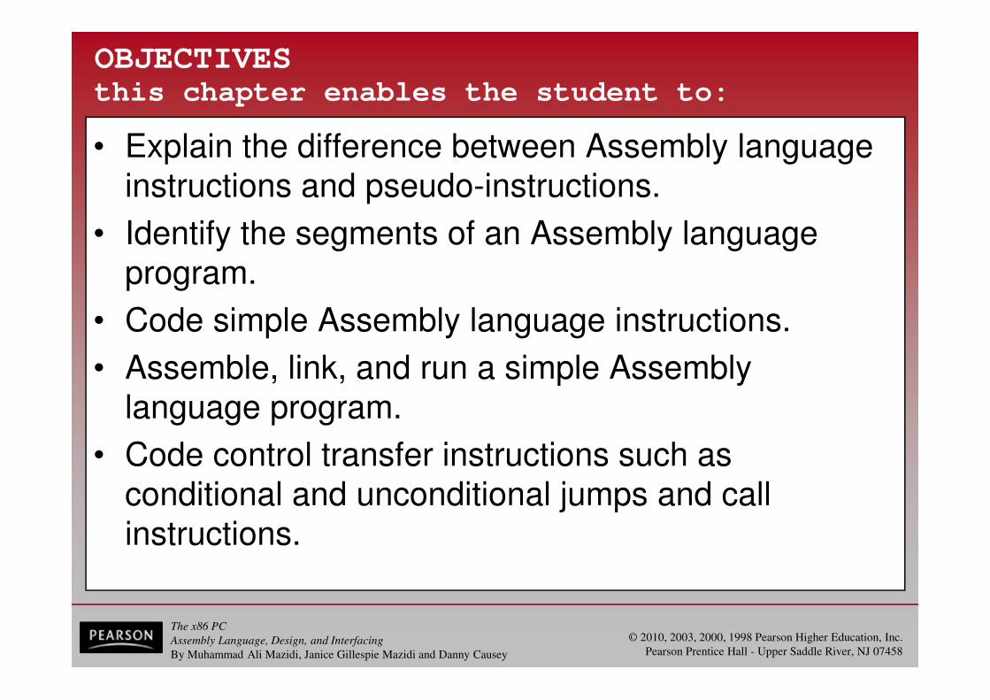
OBJECTIVESthis chapter enables the student to:
• Explain the difference between Assembly language instructions and pseudo-instructions.
• Identify the segments of an Assembly language program.
• Code simple Assembly language instructions.
• Assemble, link, and run a simple Assembly language program.
• Code control transfer instructions such as conditional and unconditional jumps and call instructions.

The x86 PC
Assembly Language, Design, and Interfacing
By Muhammad Ali Mazidi, Janice Gillespie Mazidi and Danny Causey
© 2010, 2003, 2000, 1998 Pearson Higher Education, Inc.
Pearson Prentice Hall - Upper Saddle River, NJ 07458
OBJECTIVESthis chapter enables the student to:
• Code Assembly language data directives for binary, hex, decimal, or ASCII data.
• Write an Assembly language program using either the simplified segment definition or the full segment definition.
• Explore the use of the MASM and emu8086 assemblers.
(cont)

The x86 PC
Assembly Language, Design, and Interfacing
By Muhammad Ali Mazidi, Janice Gillespie Mazidi and Danny Causey
© 2010, 2003, 2000, 1998 Pearson Higher Education, Inc.
Pearson Prentice Hall - Upper Saddle River, NJ 07458
2.0: ASSEMBLY LANGUAGE
• An Assembly language program is a series of statements, or lines.
– Either Assembly language instructions, or statements called directives.
• Directives (pseudo-instructions) give directions to the assembler about how it should translate the Assembly language instructions into machine code.
• Assembly language instructions consist of four fields:
[label:] mnemonic [operands][;comment]
– Brackets indicate that the field is optional.
• Do not type in the brackets.

The x86 PC
Assembly Language, Design, and Interfacing
By Muhammad Ali Mazidi, Janice Gillespie Mazidi and Danny Causey
© 2010, 2003, 2000, 1998 Pearson Higher Education, Inc.
Pearson Prentice Hall - Upper Saddle River, NJ 07458
2.1: DIRECTIVES AND A SAMPLE PROGRAM
assembly language instructions
• The label field allows the program to refer to a line of code by name.
– The label field cannot exceed 31 characters.
• A label must end with a colon when it refers to anopcode generating instruction.
[label:] mnemonic [operands][;comment]
The x86 PC
Assembly Language, Design, and Interfacing
By Muhammad Ali Mazidi, Janice Gillespie Mazidi and Danny Causey
© 2010, 2003, 2000, 1998 Pearson Higher Education, Inc.
Pearson Prentice Hall - Upper Saddle River, NJ 07458
2.1: DIRECTIVES AND A SAMPLE PROGRAM
assembly language instructions
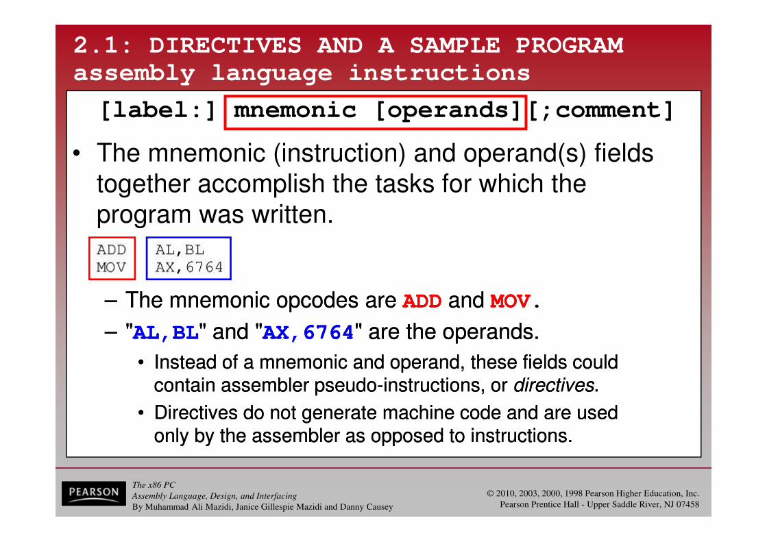
• The mnemonic (instruction) and operand(s) fields together accomplish the tasks for which the program was written.
[label:] mnemonic [operands][;comment]
– The mnemonic opcodes are ADD and MOV.
– "AL,BL" and "AX,6764" are the operands.
• Instead of a mnemonic and operand, these fields couldcontain assembler pseudo-instructions, or directives.
• Directives do not generate machine code and are usedonly by the assembler as opposed to instructions.
– The mnemonic opcodes are ADD and MOV.
– "AL,BL" and "AX,6764" are the operands.
• Instead of a mnemonic and operand, these fields couldcontain assembler pseudo-instructions, or directives.
• Directives do not generate machine code and are usedonly by the assembler as opposed to instructions.

The x86 PC
Assembly Language, Design, and Interfacing
By Muhammad Ali Mazidi, Janice Gillespie Mazidi and Danny Causey
© 2010, 2003, 2000, 1998 Pearson Higher Education, Inc.
Pearson Prentice Hall - Upper Saddle River, NJ 07458
2.1: DIRECTIVES AND A SAMPLE PROGRAM
assembly language instructions
• Examples of directives are DB, END, and ENDP.
[label:] mnemonic [operands][;comment]

The x86 PC
Assembly Language, Design, and Interfacing
By Muhammad Ali Mazidi, Janice Gillespie Mazidi and Danny Causey
© 2010, 2003, 2000, 1998 Pearson Higher Education, Inc.
Pearson Prentice Hall - Upper Saddle River, NJ 07458
2.1: DIRECTIVES AND A SAMPLE PROGRAM
assembly language instructions
• The comment field begins with a ";" and may be at the end of a line or on a line by themselves.
– The assembler ignores comments.
• Comments are optional, but highly recommended tomake it easier to read and understand the program.
[label:] mnemonic [operands][;comment]
The x86 PC
Assembly Language, Design, and Interfacing
By Muhammad Ali Mazidi, Janice Gillespie Mazidi and Danny Causey
© 2010, 2003, 2000, 1998 Pearson Higher Education, Inc.
Pearson Prentice Hall - Upper Saddle River, NJ 07458
2.1: DIRECTIVES AND A SAMPLE PROGRAM
model definition
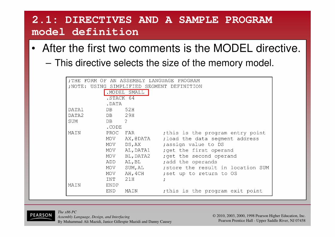
• After the first two comments is the MODEL directive.
– This directive selects the size of the memory model.
The x86 PC
Assembly Language, Design, and Interfacing
By Muhammad Ali Mazidi, Janice Gillespie Mazidi and Danny Causey
© 2010, 2003, 2000, 1998 Pearson Higher Education, Inc.
Pearson Prentice Hall - Upper Saddle River, NJ 07458
2.1: DIRECTIVES AND A SAMPLE PROGRAM
model definition
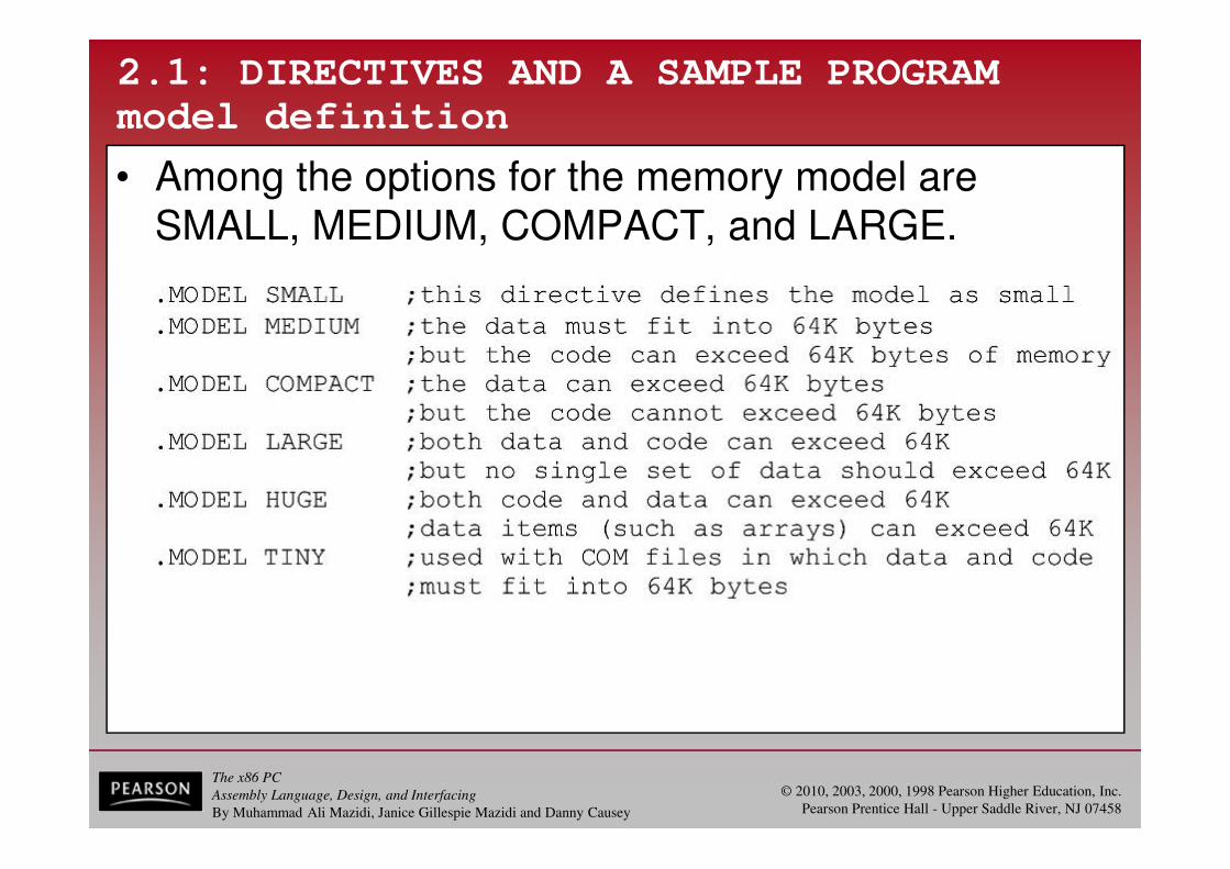
• Among the options for the memory model are SMALL, MEDIUM, COMPACT, and LARGE.

The x86 PC
Assembly Language, Design, and Interfacing
By Muhammad Ali Mazidi, Janice Gillespie Mazidi and Danny Causey
© 2010, 2003, 2000, 1998 Pearson Higher Education, Inc.
Pearson Prentice Hall - Upper Saddle River, NJ 07458
2.1: DIRECTIVES AND A SAMPLE PROGRAM
segment definition
• Every line of an Assembly language program must correspond to one an x86 CPU segment register.
– CS (code segment); DS (data segment).
– SS (stack segment); ES (extra segment).
• The simplified segment definition format uses three simple directives: ".CODE" ".DATA" ".STACK“
– Which correspond to the CS, DS, and SS registers.
• The stack segment defines storage for the stack.• The data segment defines the data the program will use.• The code segment contains Assembly language instructions.

The x86 PC
Assembly Language, Design, and Interfacing
By Muhammad Ali Mazidi, Janice Gillespie Mazidi and Danny Causey
© 2010, 2003, 2000, 1998 Pearson Higher Education, Inc.
Pearson Prentice Hall - Upper Saddle River, NJ 07458
2.1: DIRECTIVES AND A SAMPLE PROGRAM
stack segment
• This directive reserves 64 bytes of memory for the stack:

The x86 PC
Assembly Language, Design, and Interfacing
By Muhammad Ali Mazidi, Janice Gillespie Mazidi and Danny Causey
© 2010, 2003, 2000, 1998 Pearson Higher Education, Inc.
Pearson Prentice Hall - Upper Saddle River, NJ 07458
2.1: DIRECTIVES AND A SAMPLE PROGRAM
data segment
• The data segment defines three data items:
– DATA1, DATA2, and SUM.

The x86 PC
Assembly Language, Design, and Interfacing
By Muhammad Ali Mazidi, Janice Gillespie Mazidi and Danny Causey
© 2010, 2003, 2000, 1998 Pearson Higher Education, Inc.
Pearson Prentice Hall - Upper Saddle River, NJ 07458
2.1: DIRECTIVES AND A SAMPLE PROGRAM
data segment
• The DB directive is used by the assembler to allocate memory in byte-sized chunks.
– Each is defined as DB (define byte).
• Memory can be allocated in different sizes.
– Data items defined in the data segment will beaccessed in the code segment by their labels.
• DATA1 and DATA2 are given initial values in the data section.
• SUM is not given an initial value.
– But storage is set aside for it.

The x86 PC
Assembly Language, Design, and Interfacing
By Muhammad Ali Mazidi, Janice Gillespie Mazidi and Danny Causey
© 2010, 2003, 2000, 1998 Pearson Higher Education, Inc.
Pearson Prentice Hall - Upper Saddle River, NJ 07458
2.1: DIRECTIVES AND A SAMPLE PROGRAM
code segment definition
• The first line of the segment after the .CODE directive is the PROC directive.

The x86 PC
Assembly Language, Design, and Interfacing
By Muhammad Ali Mazidi, Janice Gillespie Mazidi and Danny Causey
© 2010, 2003, 2000, 1998 Pearson Higher Education, Inc.
Pearson Prentice Hall - Upper Saddle River, NJ 07458
2.1: DIRECTIVES AND A SAMPLE PROGRAM
code segment definition
• A procedure is a group of instructions designed to accomplish a specific function.
– A code segment is organized into several small procedures to make the program more structured.
• Every procedure must have a name defined by the PROC directive.
– Followed by the assembly language instructions, and closed by the ENDP directive.
• The PROC and ENDP statements must have the same label.
– The PROC directive may have the option FAR or NEAR.
• The OS requires the entry point to the user programto be a FAR procedure.
The x86 PC
Assembly Language, Design, and Interfacing
By Muhammad Ali Mazidi, Janice Gillespie Mazidi and Danny Causey
© 2010, 2003, 2000, 1998 Pearson Higher Education, Inc.
Pearson Prentice Hall - Upper Saddle River, NJ 07458
2.1: DIRECTIVES AND A SAMPLE PROGRAM
code segment definition
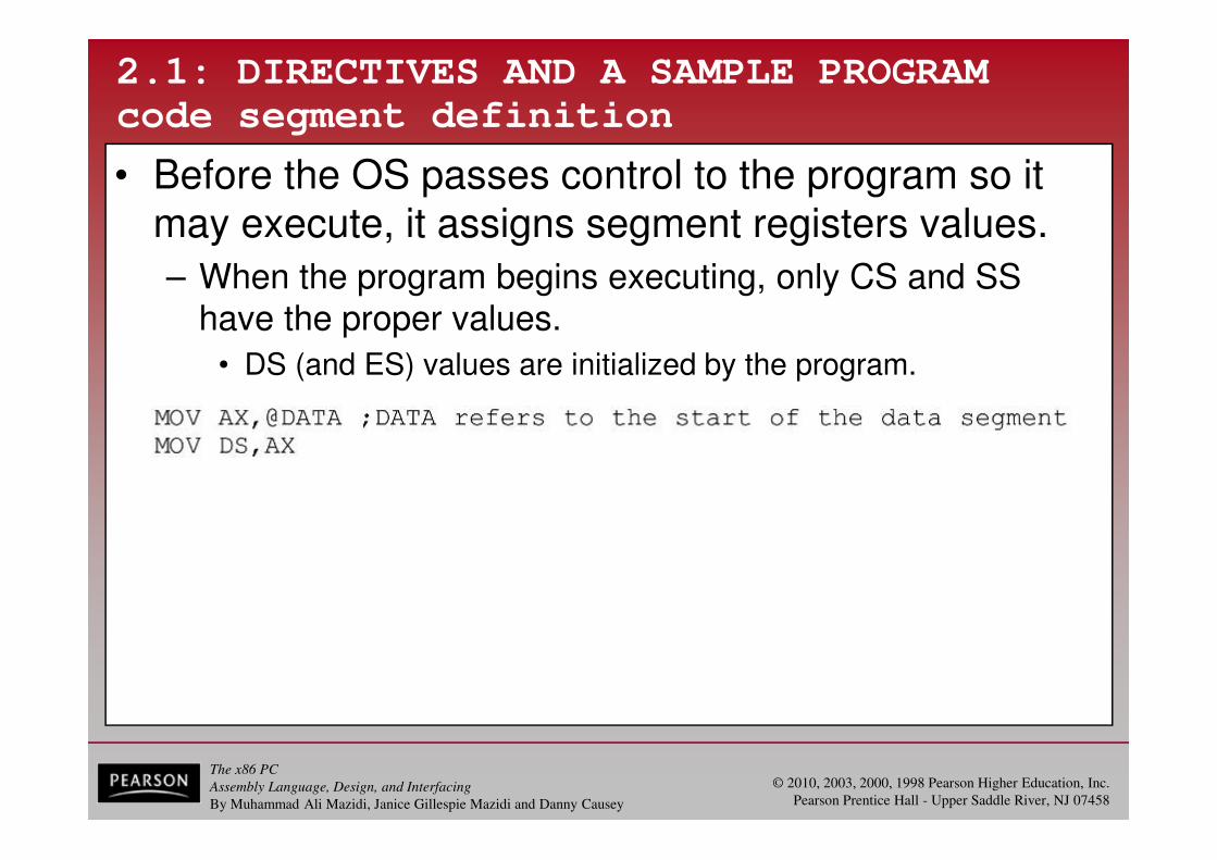
• Before the OS passes control to the program so it may execute, it assigns segment registers values.
– When the program begins executing, only CS and SS have the proper values.
• DS (and ES) values are initialized by the program.
The x86 PC
Assembly Language, Design, and Interfacing
By Muhammad Ali Mazidi, Janice Gillespie Mazidi and Danny Causey
© 2010, 2003, 2000, 1998 Pearson Higher Education, Inc.
Pearson Prentice Hall - Upper Saddle River, NJ 07458
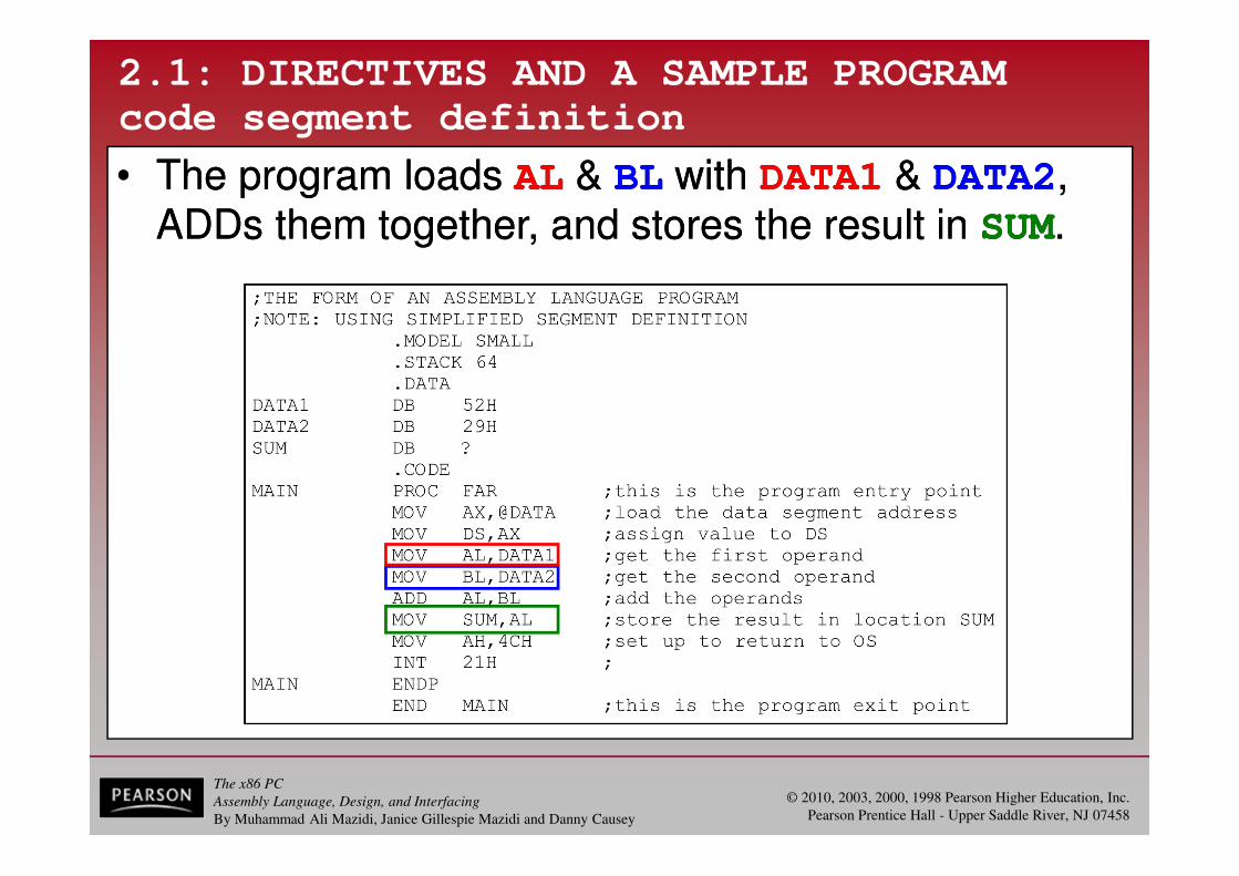
• The program loads AL & BL with DATA1 & DATA2, ADDs them together, and stores the result in SUM.
2.1: DIRECTIVES AND A SAMPLE PROGRAM
code segment definition
• The program loads AL & BL with DATA1 & DATA2, ADDs them together, and stores the result in SUM.

The x86 PC
Assembly Language, Design, and Interfacing
By Muhammad Ali Mazidi, Janice Gillespie Mazidi and Danny Causey
© 2010, 2003, 2000, 1998 Pearson Higher Education, Inc.
Pearson Prentice Hall - Upper Saddle River, NJ 07458
2.1: DIRECTIVES AND A SAMPLE PROGRAM
code segment definition
• The last instructions, "MOV AH,4CH" & "INT 21H"
return control to the operating system.
The x86 PC
Assembly Language, Design, and Interfacing
By Muhammad Ali Mazidi, Janice Gillespie Mazidi and Danny Causey
© 2010, 2003, 2000, 1998 Pearson Higher Education, Inc.
Pearson Prentice Hall - Upper Saddle River, NJ 07458
2.1: DIRECTIVES AND A SAMPLE PROGRAM
code segment definition
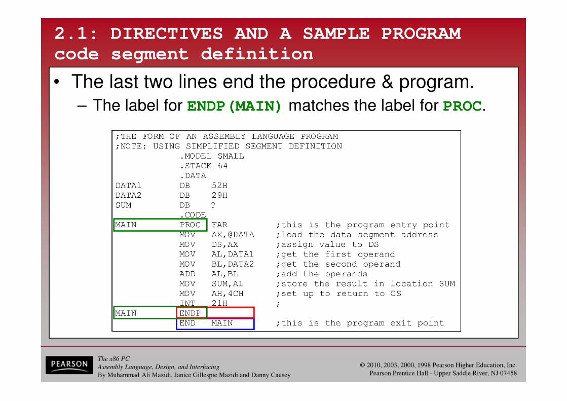
• The last two lines end the procedure & program. – The label for ENDP(MAIN) matches the label for PROC.

The x86 PC
Assembly Language, Design, and Interfacing
By Muhammad Ali Mazidi, Janice Gillespie Mazidi and Danny Causey
© 2010, 2003, 2000, 1998 Pearson Higher Education, Inc.
Pearson Prentice Hall - Upper Saddle River, NJ 07458
2.1: DIRECTIVES AND A SAMPLE PROGRAM
code segment definition
• It is handy to keep a sample shell & fill it in with the instructions and data for your program.

The x86 PC
Assembly Language, Design, and Interfacing
By Muhammad Ali Mazidi, Janice Gillespie Mazidi and Danny Causey
© 2010, 2003, 2000, 1998 Pearson Higher Education, Inc.
Pearson Prentice Hall - Upper Saddle River, NJ 07458
2.2: ASSEMBLE, LINK, AND RUN A PROGRAM
• MASM & LINK are the assembler & linker programs.
– Many editors or word processors can be used to createand/or edit the program, and produce an ASCII file.
– The steps to create an executable Assembly language program are as follows:

The x86 PC
Assembly Language, Design, and Interfacing
By Muhammad Ali Mazidi, Janice Gillespie Mazidi and Danny Causey
© 2010, 2003, 2000, 1998 Pearson Higher Education, Inc.
Pearson Prentice Hall - Upper Saddle River, NJ 07458
2.2: ASSEMBLE, LINK, AND RUN A PROGRAM
• The source file must end in ".asm“.
– The ".asm" file is assembled by an assembler, like MASM.
• The assembler will produce an object file and a list file, along with other files useful to the programmer.
• The extension for the object file must be ".obj".
– This object file is input to the LINK program, to producethe executable program that ends in ".exe".
– The ".exe" file can be run (executed) by the microprocessor.

The x86 PC
Assembly Language, Design, and Interfacing
By Muhammad Ali Mazidi, Janice Gillespie Mazidi and Danny Causey
© 2010, 2003, 2000, 1998 Pearson Higher Education, Inc.
Pearson Prentice Hall - Upper Saddle River, NJ 07458
2.2: ASSEMBLE, LINK, AND RUN A PROGRAM
Before feeding the ".obj" fileinto LINK, all syntax errorsmust be corrected.
Fixing these errors will notguarantee the program willwork as intended, as the program may contain conceptual errors.

The x86 PC
Assembly Language, Design, and Interfacing
By Muhammad Ali Mazidi, Janice Gillespie Mazidi and Danny Causey
© 2010, 2003, 2000, 1998 Pearson Higher Education, Inc.
Pearson Prentice Hall - Upper Saddle River, NJ 07458
2.2: ASSEMBLE, LINK, AND RUN A PROGRAM
• Figure 2-4 shows how an executable program is created & run by following the steps outlined above.
See the entire program listing on page 61 of your textbook.
The x86 PC
Assembly Language, Design, and Interfacing
By Muhammad Ali Mazidi, Janice Gillespie Mazidi and Danny Causey
© 2010, 2003, 2000, 1998 Pearson Higher Education, Inc.
Pearson Prentice Hall - Upper Saddle River, NJ 07458
2.2: ASSEMBLE, LINK, AND RUN A PROGRAM
PAGE and TITLE directives
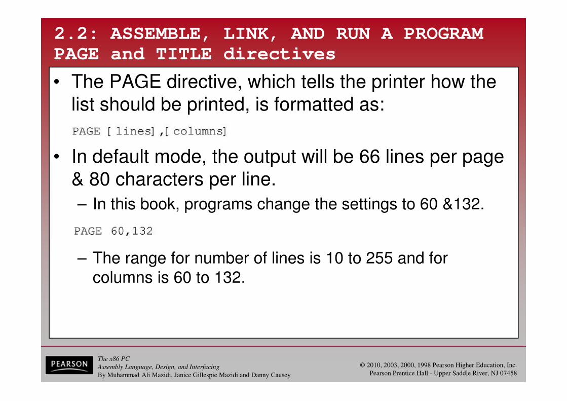
• The PAGE directive, which tells the printer how the list should be printed, is formatted as:
• In default mode, the output will be 66 lines per page & 80 characters per line.
– In this book, programs change the settings to 60 &132.
– The range for number of lines is 10 to 255 and for columns is 60 to 132.

The x86 PC
Assembly Language, Design, and Interfacing
By Muhammad Ali Mazidi, Janice Gillespie Mazidi and Danny Causey
© 2010, 2003, 2000, 1998 Pearson Higher Education, Inc.
Pearson Prentice Hall - Upper Saddle River, NJ 07458
2.2: ASSEMBLE, LINK, AND RUN A PROGRAM
PAGE and TITLE directives
• When the list is printed, the assembler can print the title of the program on top of each page.
– It is common to put the name of the program immediately after the TITLE pseudo-instruction.
• And a brief description of the function of the program.
– The text after the TITLE pseudo-instruction cannot be exceed 60 ASCII characters.

The x86 PC
Assembly Language, Design, and Interfacing
By Muhammad Ali Mazidi, Janice Gillespie Mazidi and Danny Causey
© 2010, 2003, 2000, 1998 Pearson Higher Education, Inc.
Pearson Prentice Hall - Upper Saddle River, NJ 07458
2.2: ASSEMBLE, LINK, AND RUN A PROGRAM
PAGE and TITLE directives .crf
• MASM produces another optional file, the cross-
reference, which has the extension ".crf".
– An alphabetical list of all symbols & labels in the program.
• Also program line numbers in which they are referenced.

The x86 PC
Assembly Language, Design, and Interfacing
By Muhammad Ali Mazidi, Janice Gillespie Mazidi and Danny Causey
© 2010, 2003, 2000, 1998 Pearson Higher Education, Inc.
Pearson Prentice Hall - Upper Saddle River, NJ 07458
2.2: ASSEMBLE, LINK, AND RUN A PROGRAM
LINKing the program
• The assembler (MASM) creates the opcodes, operands & offset addresses under the ".obj" file.
• The LINK program produces the ready-to-run program with the ".exe" (EXEcutable) extension.
– The LINK program sets up the file so it can be loadedby the OS and executed.
• The program can be run at the OS level, using the following command: C>myfile
– When the program name is typed in at the OS level, the OS loads the program in memory.
• Referred to as mapping, which means that the program is mapped into the physical memory of the PC.
The x86 PC
Assembly Language, Design, and Interfacing
By Muhammad Ali Mazidi, Janice Gillespie Mazidi and Danny Causey
© 2010, 2003, 2000, 1998 Pearson Higher Education, Inc.
Pearson Prentice Hall - Upper Saddle River, NJ 07458
2.2: ASSEMBLE, LINK, AND RUN A PROGRAM
LINKing the program .map
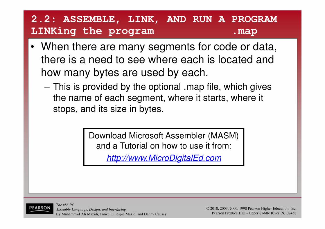
• When there are many segments for code or data, there is a need to see where each is located and how many bytes are used by each.
– This is provided by the optional .map file, which givesthe name of each segment, where it starts, where itstops, and its size in bytes.
Download Microsoft Assembler (MASM)and a Tutorial on how to use it from:
http://www.MicroDigitalEd.com
The x86 PC
Assembly Language, Design, and Interfacing
By Muhammad Ali Mazidi, Janice Gillespie Mazidi and Danny Causey
© 2010, 2003, 2000, 1998 Pearson Higher Education, Inc.
Pearson Prentice Hall - Upper Saddle River, NJ 07458
2.3: MORE SAMPLE PROGRAMS
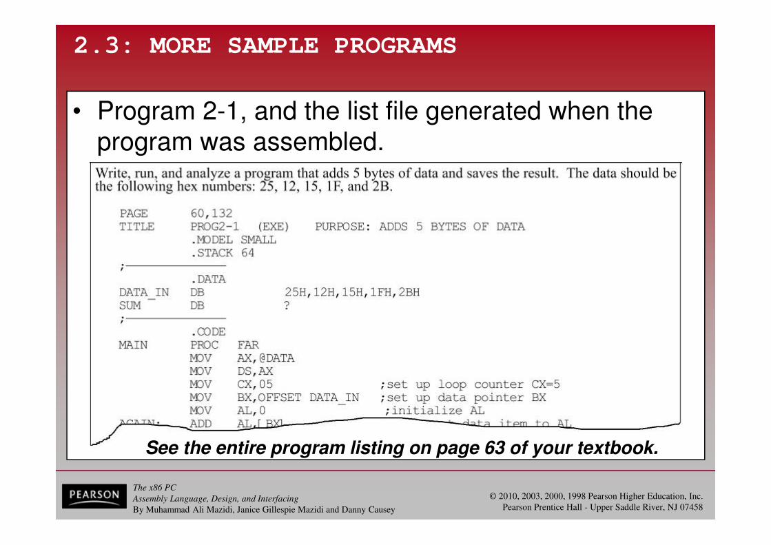
See the entire program listing on page 63 of your textbook.
• Program 2-1, and the list file generated when the program was assembled.

The x86 PC
Assembly Language, Design, and Interfacing
By Muhammad Ali Mazidi, Janice Gillespie Mazidi and Danny Causey
© 2010, 2003, 2000, 1998 Pearson Higher Education, Inc.
Pearson Prentice Hall - Upper Saddle River, NJ 07458
2.3: MORE SAMPLE PROGRAMS
analysis of Program 2-1
• The commands used in running Program 2-1 were:
– (1) u, to unassemble the code from cs:0 for 19 bytes.
– (2) d, to dump the contents of memory from 1066:0 for the next F bytes.
– (3) g, to go. (run the program)

The x86 PC
Assembly Language, Design, and Interfacing
By Muhammad Ali Mazidi, Janice Gillespie Mazidi and Danny Causey
© 2010, 2003, 2000, 1998 Pearson Higher Education, Inc.
Pearson Prentice Hall - Upper Saddle River, NJ 07458
2.3: MORE SAMPLE PROGRAMS
analysis of Program 2-1
• Program 2-1, explained instruction by instruction:– "MOV CX,05" will load the value 05 into the CX register.
• Used by the program as a counter for iteration (looping).
– "MOV BX,OFFSET DATA_IN" will load into BX the
offset address assigned to DATA.
• The assembler starts at offset 0000 and uses memory forthe data, then assigns the next available offset memory for SUM (in this case, 0005).
– "ADD AL,[BX]" adds the contents of the memory
location pointed at by the register BX to AL. • Note that [BX] is a pointer to a memory location.
– "INC BX" increments the pointer by adding 1 to BX.
• This will cause BX to point to the next data item. (next byte)

The x86 PC
Assembly Language, Design, and Interfacing
By Muhammad Ali Mazidi, Janice Gillespie Mazidi and Danny Causey
© 2010, 2003, 2000, 1998 Pearson Higher Education, Inc.
Pearson Prentice Hall - Upper Saddle River, NJ 07458
2.3: MORE SAMPLE PROGRAMS
analysis of Program 2-1
• Program 2-1, explained instruction by instruction:
– "DEC CX" will decrement (subtract 1 from) the CX
counter and set the zero flag high if CX becomes zero.
– "JNZ AGAIN" will jump back to the label AGAIN as
long as the zero flag is indicating that CX is not zero. • "JNZ AGAIN" will not jump only after the zero flag has been
set high by the "DEC CX" instruction (CX becomes zero).
– When CX becomes zero, this means that the loop is completed and all five numbers have been added to AL.

The x86 PC
Assembly Language, Design, and Interfacing
By Muhammad Ali Mazidi, Janice Gillespie Mazidi and Danny Causey
© 2010, 2003, 2000, 1998 Pearson Higher Education, Inc.
Pearson Prentice Hall - Upper Saddle River, NJ 07458
2.3: MORE SAMPLE PROGRAMS
various approaches to Program 2-1
• Variations of Program 2-1 clarify use of addressing modes, and show that the x86 can use any general-purpose register for arithmetic and logic operations.

The x86 PC
Assembly Language, Design, and Interfacing
By Muhammad Ali Mazidi, Janice Gillespie Mazidi and Danny Causey
© 2010, 2003, 2000, 1998 Pearson Higher Education, Inc.
Pearson Prentice Hall - Upper Saddle River, NJ 07458
2.3: MORE SAMPLE PROGRAMS
analysis of Program 2-2
See the entire program listing on page 66 of your textbook.
• The 16-bit data (a word) is stored with the low-order byte first, referred to as "little endian."
The x86 PC
Assembly Language, Design, and Interfacing
By Muhammad Ali Mazidi, Janice Gillespie Mazidi and Danny Causey
© 2010, 2003, 2000, 1998 Pearson Higher Education, Inc.
Pearson Prentice Hall - Upper Saddle River, NJ 07458
2.3: MORE SAMPLE PROGRAMS
analysis of Program 2-2
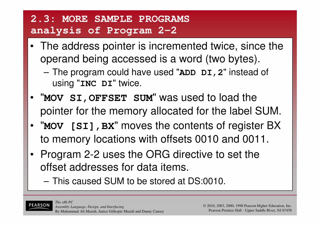
• The address pointer is incremented twice, since the operand being accessed is a word (two bytes). – The program could have used "ADD DI,2" instead of
using "INC DI" twice.
• "MOV SI,OFFSET SUM" was used to load the
pointer for the memory allocated for the label SUM.
• "MOV [SI],BX" moves the contents of register BX
to memory locations with offsets 0010 and 0011.
• Program 2-2 uses the ORG directive to set the offset addresses for data items.
– This caused SUM to be stored at DS:0010.

The x86 PC
Assembly Language, Design, and Interfacing
By Muhammad Ali Mazidi, Janice Gillespie Mazidi and Danny Causey
© 2010, 2003, 2000, 1998 Pearson Higher Education, Inc.
Pearson Prentice Hall - Upper Saddle River, NJ 07458
2.3: MORE SAMPLE PROGRAMS
analysis of Program 2-3
See the entire program listing on page 67 of your textbook.
• Program 2-3 shows the data segment being dumped before and after the program was run.
The x86 PC
Assembly Language, Design, and Interfacing
By Muhammad Ali Mazidi, Janice Gillespie Mazidi and Danny Causey
© 2010, 2003, 2000, 1998 Pearson Higher Education, Inc.
Pearson Prentice Hall - Upper Saddle River, NJ 07458
2.3: MORE SAMPLE PROGRAMS
analysis of Program 2-3
• C4 was coded in the data segments as 0C4.
– Indicating that C is a hex number and not a letter.
• Required if the first digit is a hex digit A through F.
• This program uses registers SI & DI as pointersto the data items being manipulated.
– The first is a pointer to the data item to be copied.
– The second points to the location the data is copied to.
• With each iteration of the loop, both data pointers are incremented to point to the next byte.
The x86 PC
Assembly Language, Design, and Interfacing
By Muhammad Ali Mazidi, Janice Gillespie Mazidi and Danny Causey
© 2010, 2003, 2000, 1998 Pearson Higher Education, Inc.
Pearson Prentice Hall - Upper Saddle River, NJ 07458
2.4: CONTROL TRANSFER INSTRUCTIONS
FAR and NEAR
• In the sequence of instructions, it is often necessary to transfer program control to a different location.
– If control is transferred to a memory location within the current code segment, it is NEAR.
• Sometimes called intrasegment. (within segment)
– If control is transferred outside the current code segment, it is a FAR jump.
• Or intersegment. (between segments)
The x86 PC
Assembly Language, Design, and Interfacing
By Muhammad Ali Mazidi, Janice Gillespie Mazidi and Danny Causey
© 2010, 2003, 2000, 1998 Pearson Higher Education, Inc.
Pearson Prentice Hall - Upper Saddle River, NJ 07458
2.4: CONTROL TRANSFER INSTRUCTIONS
FAR and NEAR
• As the CS:IP registers always point to the address of the next instruction to be executed, they must be updated when a control transfer is executed.
– In a NEAR jump, the IP is updated and CS remains the same, since control is still inside the current code segment.
– In a FAR jump, because control is passing outside the current code segment, both CS and IP have to be updated to the new values.

The x86 PC
Assembly Language, Design, and Interfacing
By Muhammad Ali Mazidi, Janice Gillespie Mazidi and Danny Causey
© 2010, 2003, 2000, 1998 Pearson Higher Education, Inc.
Pearson Prentice Hall - Upper Saddle River, NJ 07458
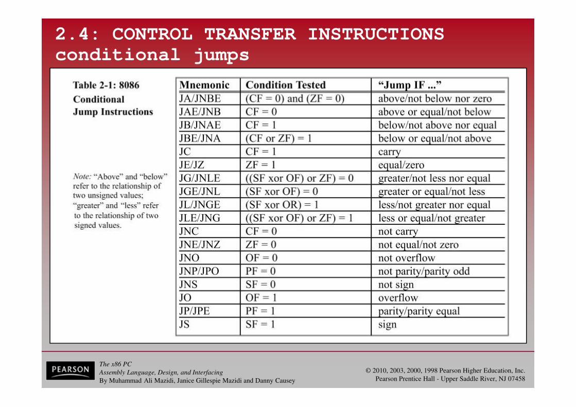
2.4: CONTROL TRANSFER INSTRUCTIONS
conditional jumps
• Conditional jumps have mnemonics such as JNZ (jump not zero) and JC (jump if carry).
– In the conditional jump, control is transferred to a new location if a certain condition is met.
– The flag register indicates the current condition.
• For example, with "JNZ label", the processor looks at the zero flag to see if it is raised.
– If not, the CPU starts to fetch and execute instructions from the address of the label.
– If ZF = 1, it will not jump but will execute the next instruction below the JNZ.
The x86 PC
Assembly Language, Design, and Interfacing
By Muhammad Ali Mazidi, Janice Gillespie Mazidi and Danny Causey
© 2010, 2003, 2000, 1998 Pearson Higher Education, Inc.
Pearson Prentice Hall - Upper Saddle River, NJ 07458
2.4: CONTROL TRANSFER INSTRUCTIONS
conditional jumps
The x86 PC
Assembly Language, Design, and Interfacing
By Muhammad Ali Mazidi, Janice Gillespie Mazidi and Danny Causey
© 2010, 2003, 2000, 1998 Pearson Higher Education, Inc.
Pearson Prentice Hall - Upper Saddle River, NJ 07458
2.4: CONTROL TRANSFER INSTRUCTIONS
short jumps
• All conditional jumps are short jumps.
– The address of the target must be within -128 to +127 bytes of the IP.
• The conditional jump is a two-byte instruction.
– One byte is the opcode of the J condition.
– The second byte is a value between 00 and FF.
• An offset range of 00 to FF gives 256 possible addresses.
• In a jump backward, the second byte is the 2's complement of the displacement value
The x86 PC
Assembly Language, Design, and Interfacing
By Muhammad Ali Mazidi, Janice Gillespie Mazidi and Danny Causey
© 2010, 2003, 2000, 1998 Pearson Higher Education, Inc.
Pearson Prentice Hall - Upper Saddle River, NJ 07458
2.4: CONTROL TRANSFER INSTRUCTIONS
short jumps
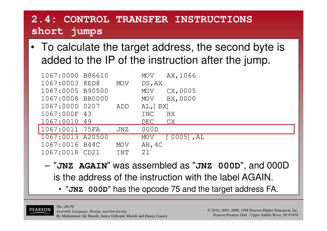
• To calculate the target address, the second byte is added to the IP of the instruction after the jump.
– "JNZ AGAIN" was assembled as "JNZ 000D", and 000D
is the address of the instruction with the label AGAIN. • "JNZ 000D" has the opcode 75 and the target address FA.
The x86 PC
Assembly Language, Design, and Interfacing
By Muhammad Ali Mazidi, Janice Gillespie Mazidi and Danny Causey
© 2010, 2003, 2000, 1998 Pearson Higher Education, Inc.
Pearson Prentice Hall - Upper Saddle River, NJ 07458
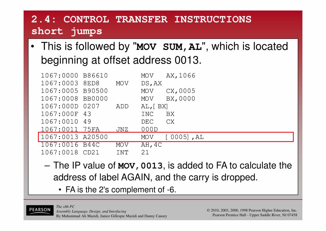
– The IP value of MOV,0013, is added to FA to calculate the
address of label AGAIN, and the carry is dropped.
• FA is the 2's complement of -6.
2.4: CONTROL TRANSFER INSTRUCTIONS
short jumps
• This is followed by "MOV SUM,AL", which is located
beginning at offset address 0013.

The x86 PC
Assembly Language, Design, and Interfacing
By Muhammad Ali Mazidi, Janice Gillespie Mazidi and Danny Causey
© 2010, 2003, 2000, 1998 Pearson Higher Education, Inc.
Pearson Prentice Hall - Upper Saddle River, NJ 07458
2.4: CONTROL TRANSFER INSTRUCTIONS
short jumps
• Calculate a forward jump target address by adding the IP of the following instruction to the operand.
– The displacement value is positive, as shown.
– "JB NEXT" has the opcode 72, the target address 06and is located at IP = 000A and 000B.
• The jump is 6 bytes from the next instruction, is IP = 000C.
• Adding gives us 000CH + 0006H = 0012H, which is the exact address of the NEXT label.

The x86 PC
Assembly Language, Design, and Interfacing
By Muhammad Ali Mazidi, Janice Gillespie Mazidi and Danny Causey
© 2010, 2003, 2000, 1998 Pearson Higher Education, Inc.
Pearson Prentice Hall - Upper Saddle River, NJ 07458
2.4: CONTROL TRANSFER INSTRUCTIONS
short jumps
• For conditional jumps, the address of the target address can never be more than -128 to +127 bytes away from the IP associated with the instruction following the jump.
– Any attempt is made to violate this rule will generate a "relative jump out of range" message.

The x86 PC
Assembly Language, Design, and Interfacing
By Muhammad Ali Mazidi, Janice Gillespie Mazidi and Danny Causey
© 2010, 2003, 2000, 1998 Pearson Higher Education, Inc.
Pearson Prentice Hall - Upper Saddle River, NJ 07458
2.4: CONTROL TRANSFER INSTRUCTIONS
unconditional jumps
• An unconditional jump transfers control to the target location label unconditionally, in the following forms:– SHORT JUMP - in the format "JMP SHORT label".
• A jump within -128 to +127 bytes of memory relative to the address of the current IP, opcode EB.
– NEAR JUMP - the default, has the format "JMP label".
• A jump within the current code segment, opcode E9.
• The target address can be any of the addressing modes of direct, register, register indirect, or memory indirect:
– Direct JUMP - exactly like the short jump.
• Except that the target address can be anywhere in the segment in the range +32767 to -32768 of the current IP.

The x86 PC
Assembly Language, Design, and Interfacing
By Muhammad Ali Mazidi, Janice Gillespie Mazidi and Danny Causey
© 2010, 2003, 2000, 1998 Pearson Higher Education, Inc.
Pearson Prentice Hall - Upper Saddle River, NJ 07458
2.4: CONTROL TRANSFER INSTRUCTIONS
unconditional jumps
• An unconditional jump transfers control to the target location label unconditionally, in the following forms:
– Register indirect JUMP - target address is in a register. • In "JMP BX", IP takes the value BX.
– Memory indirect JMP - target address is the contentsof two memory locations, pointed at by the register.
• "JMP [DI]" will replace the IP with the contents of memory
locations pointed at by DI and DI+1.
– FAR JUMP - in the format "JMP FAR PTR label".
register.
• A jump out of the current code segment
• IP and CS are both replaced with new values.
The x86 PC
Assembly Language, Design, and Interfacing
By Muhammad Ali Mazidi, Janice Gillespie Mazidi and Danny Causey
© 2010, 2003, 2000, 1998 Pearson Higher Education, Inc.
Pearson Prentice Hall - Upper Saddle River, NJ 07458
2.4: CONTROL TRANSFER INSTRUCTIONS
CALL statements
• The CALL instruction is used to call a procedure, to perform tasks that need to be performed frequently.
– The target address could be in the current segment, in which case it will be a NEAR call or outside the current CS segment, which is a FAR call.
• The microprocessor saves the address of the instruction following the call on the stack.
– To know where to return, after executing the subroutine.
• In the NEAR call only the IP is saved on the stack.
• In a FAR call both CS and IP are saved.

The x86 PC
Assembly Language, Design, and Interfacing
By Muhammad Ali Mazidi, Janice Gillespie Mazidi and Danny Causey
© 2010, 2003, 2000, 1998 Pearson Higher Education, Inc.
Pearson Prentice Hall - Upper Saddle River, NJ 07458
– Since this is a NEAR call, only IPis saved on the stack.
• The IP address 0206, which belongsto the "MOV AX,142F" instruction,
is saved on the stack.
– Since this is a NEAR call, only IPis saved on the stack.
• The IP address 0206, which belongsto the "MOV AX,142F" instruction,
is saved on the stack.
2.4: CONTROL TRANSFER INSTRUCTIONS
CALL statements
• For control to be transferred back to the caller, the last subroutine instruction must be RET (return).
– For NEAR calls, the IP is restored.
– For FAR calls, CS & IP are restored.
• Assume SP = FFFEH:
The x86 PC
Assembly Language, Design, and Interfacing
By Muhammad Ali Mazidi, Janice Gillespie Mazidi and Danny Causey
© 2010, 2003, 2000, 1998 Pearson Higher Education, Inc.
Pearson Prentice Hall - Upper Saddle River, NJ 07458
2.4: CONTROL TRANSFER INSTRUCTIONS
short jumps
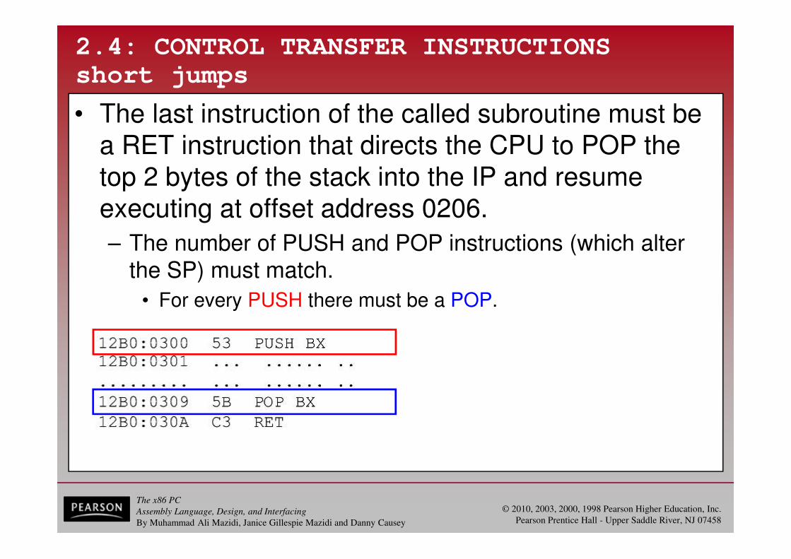
• The last instruction of the called subroutine must be a RET instruction that directs the CPU to POP the top 2 bytes of the stack into the IP and resume executing at offset address 0206.
– The number of PUSH and POP instructions (which alter the SP) must match.
• For every PUSH there must be a POP.
The x86 PC
Assembly Language, Design, and Interfacing
By Muhammad Ali Mazidi, Janice Gillespie Mazidi and Danny Causey
© 2010, 2003, 2000, 1998 Pearson Higher Education, Inc.
Pearson Prentice Hall - Upper Saddle River, NJ 07458
2.4: CONTROL TRANSFER INSTRUCTIONS
assembly language subroutines
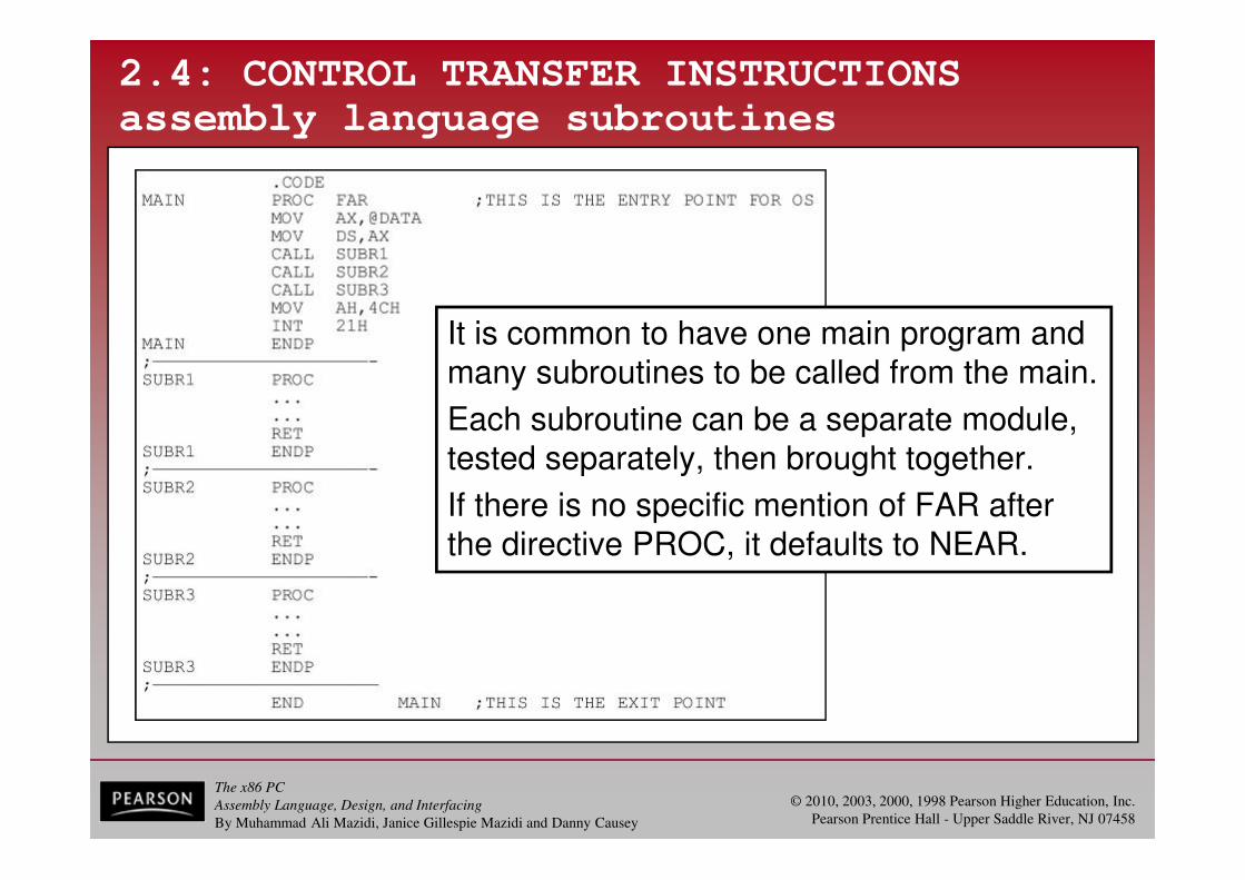
It is common to have one main program and many subroutines to be called from the main.
Each subroutine can be a separate module, tested separately, then brought together.
If there is no specific mention of FAR afterthe directive PROC, it defaults to NEAR.
The x86 PC
Assembly Language, Design, and Interfacing
By Muhammad Ali Mazidi, Janice Gillespie Mazidi and Danny Causey
© 2010, 2003, 2000, 1998 Pearson Higher Education, Inc.
Pearson Prentice Hall - Upper Saddle River, NJ 07458
2.4: CONTROL TRANSFER INSTRUCTIONS
rules for names in Assembly language
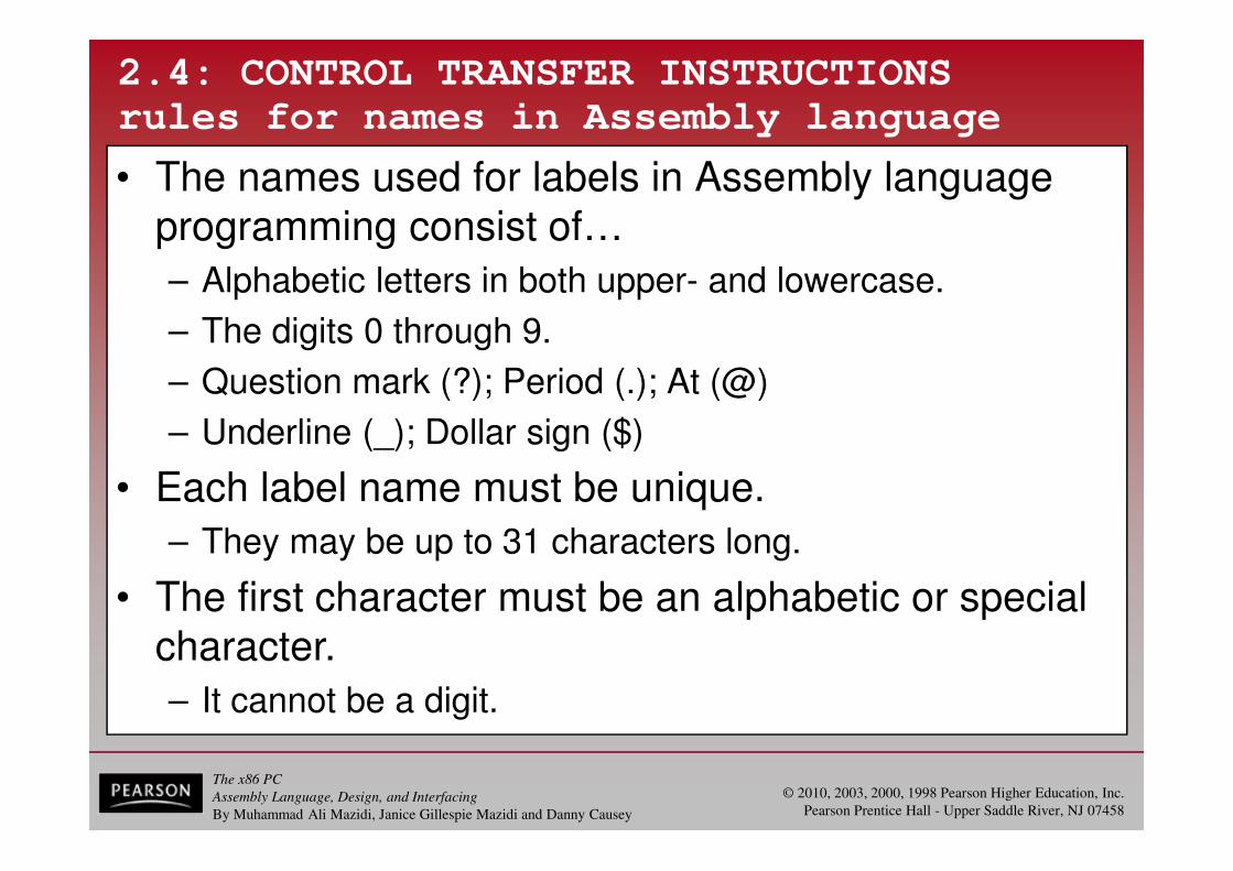
• The names used for labels in Assembly language programming consist of…
– Alphabetic letters in both upper- and lowercase.
– The digits 0 through 9.
– Question mark (?); Period (.); At (@)
– Underline (_); Dollar sign ($)
• Each label name must be unique.
– They may be up to 31 characters long.
• The first character must be an alphabetic or special character.
– It cannot be a digit.

The x86 PC
Assembly Language, Design, and Interfacing
By Muhammad Ali Mazidi, Janice Gillespie Mazidi and Danny Causey
© 2010, 2003, 2000, 1998 Pearson Higher Education, Inc.
Pearson Prentice Hall - Upper Saddle River, NJ 07458
2.4: CONTROL TRANSFER INSTRUCTIONS
rules for names in Assembly language
• The period can only be used as the first character.
– This is not recommended since later versions of MASM have several reserved words that begin with a period.

The x86 PC
Assembly Language, Design, and Interfacing
By Muhammad Ali Mazidi, Janice Gillespie Mazidi and Danny Causey
© 2010, 2003, 2000, 1998 Pearson Higher Education, Inc.
Pearson Prentice Hall - Upper Saddle River, NJ 07458
2.5: DATA TYPES AND DATA DEFINITION
x86 data types
• The 8088/86 processor supports many data types.
– Data types can be 8- or 16-bit, positive or negative.
• The programmer must break down data larger than16 bits (0000 to FFFFH, or 0 to 65535 in decimal).
– A number less than 8 bits wide must be coded asan 8-bit register with the higher digits as zero.
• A number is less than 16 bits wide must use all 16 bits.

The x86 PC
Assembly Language, Design, and Interfacing
By Muhammad Ali Mazidi, Janice Gillespie Mazidi and Danny Causey
© 2010, 2003, 2000, 1998 Pearson Higher Education, Inc.
Pearson Prentice Hall - Upper Saddle River, NJ 07458
2.5: DATA TYPES AND DATA DEFINITION
ORG origin
• ORG is used to indicate the beginning of the offset address.
– The number after ORG can be either in hex or in decimal.
• If the number is not followed by H, it is decimal and the assembler will convert it to hex.

The x86 PC
Assembly Language, Design, and Interfacing
By Muhammad Ali Mazidi, Janice Gillespie Mazidi and Danny Causey
© 2010, 2003, 2000, 1998 Pearson Higher Education, Inc.
Pearson Prentice Hall - Upper Saddle River, NJ 07458
2.5: DATA TYPES AND DATA DEFINITION
DB define byte
• One of the most widely used data directives, it allows allocation of memory in byte-sized chunks.
– This is the smallest allocation unit permitted.
– DB can define numbers in decimal, binary, hex, & ASCII. • D after the decimal number is optional.
• B (binary) and H (hexadecimal) is required.
• To indicate ASCII, place the string in single quotation marks.
• DB is the only directive that can be used to define ASCII strings larger than two characters.
– It should be used for all ASCII data definitions.

The x86 PC
Assembly Language, Design, and Interfacing
By Muhammad Ali Mazidi, Janice Gillespie Mazidi and Danny Causey
© 2010, 2003, 2000, 1998 Pearson Higher Education, Inc.
Pearson Prentice Hall - Upper Saddle River, NJ 07458
2.5: DATA TYPES AND DATA DEFINITION
DB define byte
• Some DB examples:
– Single or double quotes can be used around ASCII strings.
• Useful for strings, which should contain a single quote,such as "O'Leary".

The x86 PC
Assembly Language, Design, and Interfacing
By Muhammad Ali Mazidi, Janice Gillespie Mazidi and Danny Causey
© 2010, 2003, 2000, 1998 Pearson Higher Education, Inc.
Pearson Prentice Hall - Upper Saddle River, NJ 07458
2.5: DATA TYPES AND DATA DEFINITION
DB define byte
• List file for DB examples.
The x86 PC
Assembly Language, Design, and Interfacing
By Muhammad Ali Mazidi, Janice Gillespie Mazidi and Danny Causey
© 2010, 2003, 2000, 1998 Pearson Higher Education, Inc.
Pearson Prentice Hall - Upper Saddle River, NJ 07458
2.5: DATA TYPES AND DATA DEFINITION
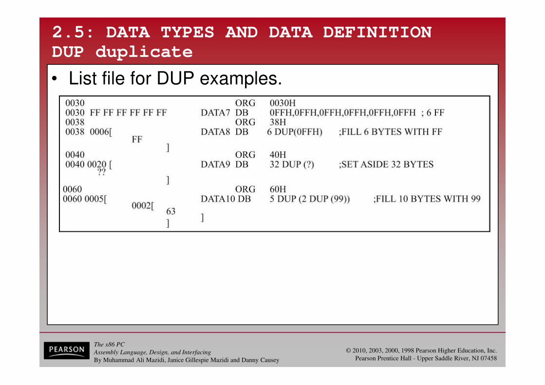
DUP duplicate
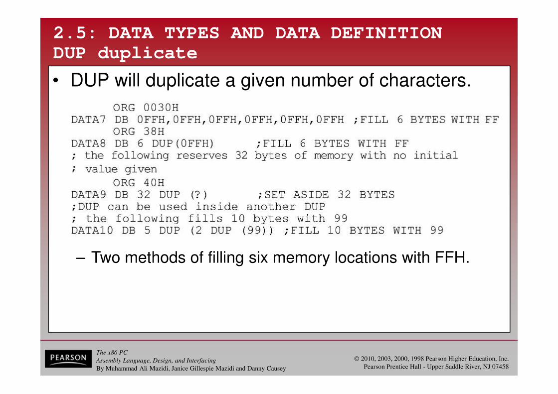
• DUP will duplicate a given number of characters.
– Two methods of filling six memory locations with FFH.
The x86 PC
Assembly Language, Design, and Interfacing
By Muhammad Ali Mazidi, Janice Gillespie Mazidi and Danny Causey
© 2010, 2003, 2000, 1998 Pearson Higher Education, Inc.
Pearson Prentice Hall - Upper Saddle River, NJ 07458
2.5: DATA TYPES AND DATA DEFINITION
DUP duplicate
• List file for DUP examples.

The x86 PC
Assembly Language, Design, and Interfacing
By Muhammad Ali Mazidi, Janice Gillespie Mazidi and Danny Causey
© 2010, 2003, 2000, 1998 Pearson Higher Education, Inc.
Pearson Prentice Hall - Upper Saddle River, NJ 07458
2.5: DATA TYPES AND DATA DEFINITION
DW define word
• DW is used to allocate memory 2 bytes (one word) at a time:
• List file for DW examples.
The x86 PC
Assembly Language, Design, and Interfacing
By Muhammad Ali Mazidi, Janice Gillespie Mazidi and Danny Causey
© 2010, 2003, 2000, 1998 Pearson Higher Education, Inc.
Pearson Prentice Hall - Upper Saddle River, NJ 07458
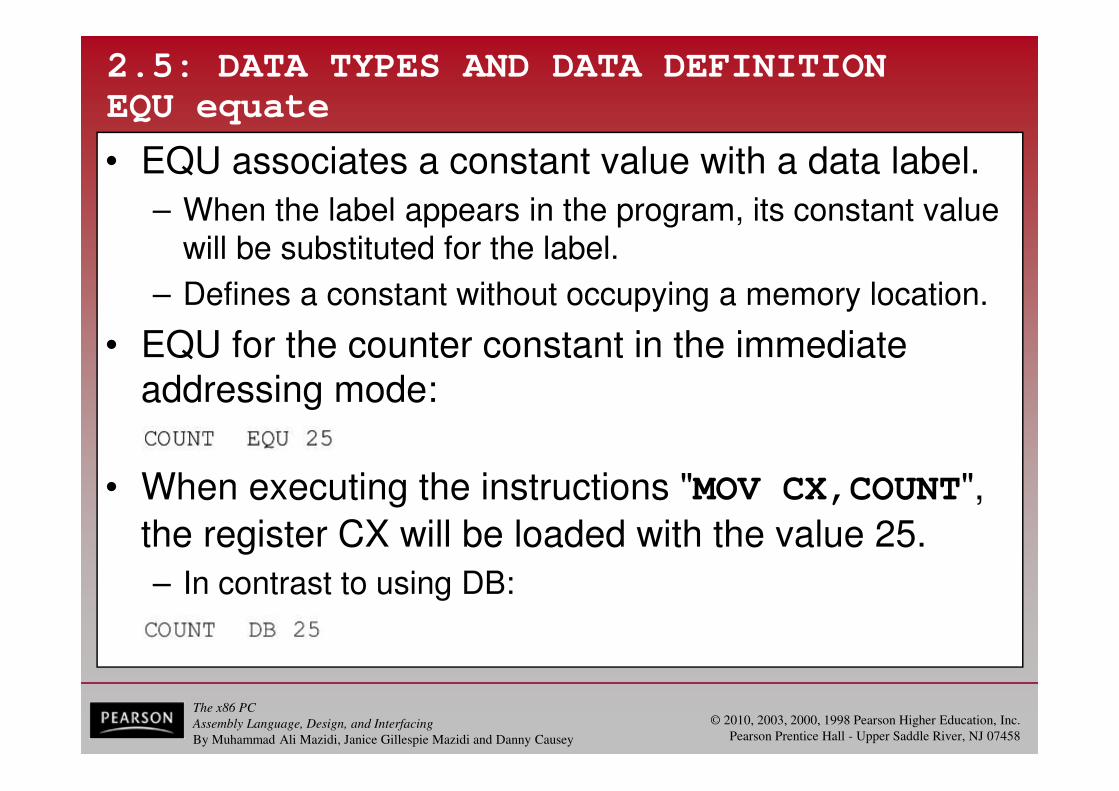
• When executing the instructions "MOV CX,COUNT",
the register CX will be loaded with the value 25.
– In contrast to using DB:
2.5: DATA TYPES AND DATA DEFINITION
EQU equate
• EQU associates a constant value with a data label.
– When the label appears in the program, its constant value will be substituted for the label.
– Defines a constant without occupying a memory location.
• EQU for the counter constant in the immediate addressing mode:

The x86 PC
Assembly Language, Design, and Interfacing
By Muhammad Ali Mazidi, Janice Gillespie Mazidi and Danny Causey
© 2010, 2003, 2000, 1998 Pearson Higher Education, Inc.
Pearson Prentice Hall - Upper Saddle River, NJ 07458
2.5: DATA TYPES AND DATA DEFINITION
EQU equate
• When executing the same instruction "MOV CX,COUNT" it will be in the direct addressing mode.
– EQU can also be used in the data segment:
– Assume a constant (a fixed value) used in manydifferent places in the data and code segments.
• By use of EQU, one can change it once and theassembler will change all of them.

The x86 PC
Assembly Language, Design, and Interfacing
By Muhammad Ali Mazidi, Janice Gillespie Mazidi and Danny Causey
© 2010, 2003, 2000, 1998 Pearson Higher Education, Inc.
Pearson Prentice Hall - Upper Saddle River, NJ 07458
2.5: DATA TYPES AND DATA DEFINITION
DD define doubleword
• The DD directive is used to allocate memory locations that are 4 bytes (two words) in size.
– Data is converted to hex & placed in memory locations
• Low byte to low address and high byte to high address.
• List file for DD examples.

The x86 PC
Assembly Language, Design, and Interfacing
By Muhammad Ali Mazidi, Janice Gillespie Mazidi and Danny Causey
© 2010, 2003, 2000, 1998 Pearson Higher Education, Inc.
Pearson Prentice Hall - Upper Saddle River, NJ 07458
2.5: DATA TYPES AND DATA DEFINITION
DQ define quadword
• DQ is used to allocate memory 8 bytes (four words) in size, to represent any variable up to 64 bits wide:
• List file for DQ examples.
The x86 PC
Assembly Language, Design, and Interfacing
By Muhammad Ali Mazidi, Janice Gillespie Mazidi and Danny Causey
© 2010, 2003, 2000, 1998 Pearson Higher Education, Inc.
Pearson Prentice Hall - Upper Saddle River, NJ 07458
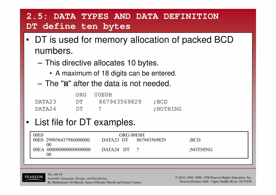
2.5: DATA TYPES AND DATA DEFINITION
DT define ten bytes
• DT is used for memory allocation of packed BCD numbers.
– This directive allocates 10 bytes.
• A maximum of 18 digits can be entered.
– The "H" after the data is not needed.
• List file for DT examples.
The x86 PC
Assembly Language, Design, and Interfacing
By Muhammad Ali Mazidi, Janice Gillespie Mazidi and Danny Causey
© 2010, 2003, 2000, 1998 Pearson Higher Education, Inc.
Pearson Prentice Hall - Upper Saddle River, NJ 07458
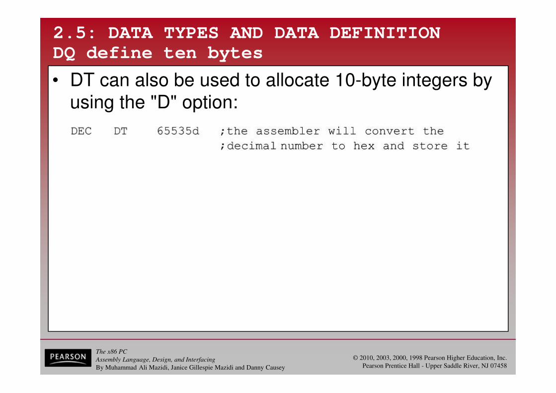
2.5: DATA TYPES AND DATA DEFINITION
DQ define ten bytes
• DT can also be used to allocate 10-byte integers by using the "D" option:
The x86 PC
Assembly Language, Design, and Interfacing
By Muhammad Ali Mazidi, Janice Gillespie Mazidi and Danny Causey
© 2010, 2003, 2000, 1998 Pearson Higher Education, Inc.
Pearson Prentice Hall - Upper Saddle River, NJ 07458
2.5: DATA TYPES AND DATA DEFINITION
directives
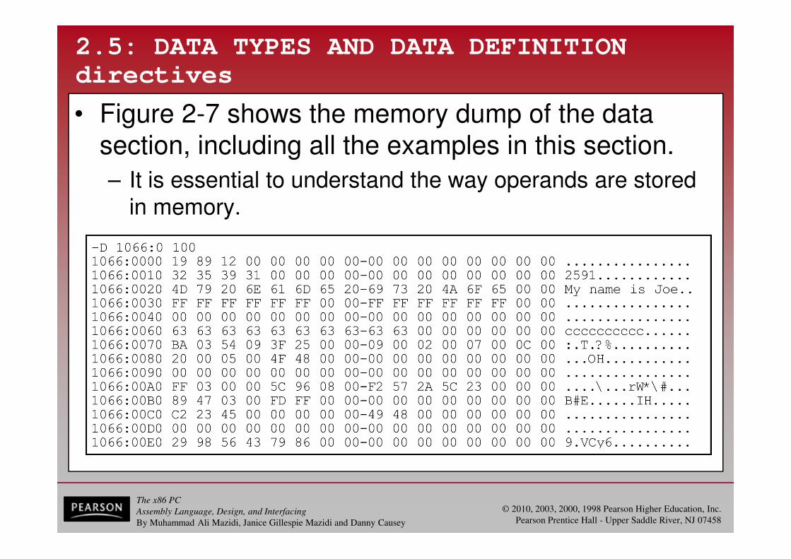
• Figure 2-7 shows the memory dump of the data section, including all the examples in this section.
– It is essential to understand the way operands are stored in memory.

The x86 PC
Assembly Language, Design, and Interfacing
By Muhammad Ali Mazidi, Janice Gillespie Mazidi and Danny Causey
© 2010, 2003, 2000, 1998 Pearson Higher Education, Inc.
Pearson Prentice Hall - Upper Saddle River, NJ 07458
2.5: DATA TYPES AND DATA DEFINITION
directives
• All of the data directives use the little endian format.
– For ASCII data, only DB can define data of any length.
• Use of DD, DQ, or DT directives for ASCII strings of morethan 2 bytes gives an assembly error.

The x86 PC
Assembly Language, Design, and Interfacing
By Muhammad Ali Mazidi, Janice Gillespie Mazidi and Danny Causey
© 2010, 2003, 2000, 1998 Pearson Higher Education, Inc.
Pearson Prentice Hall - Upper Saddle River, NJ 07458
2.5: DATA TYPES AND DATA DEFINITION
directives
• Review "DATA20 DQ 4523C2", residing in memory
starting at offset 00C0H.
– C2, the least significant byte, is in location 00C0, with23 in 00C1, and 45, the most significant byte, in 00C2.
The x86 PC
Assembly Language, Design, and Interfacing
By Muhammad Ali Mazidi, Janice Gillespie Mazidi and Danny Causey
© 2010, 2003, 2000, 1998 Pearson Higher Education, Inc.
Pearson Prentice Hall - Upper Saddle River, NJ 07458
2.5: DATA TYPES AND DATA DEFINITION
directives
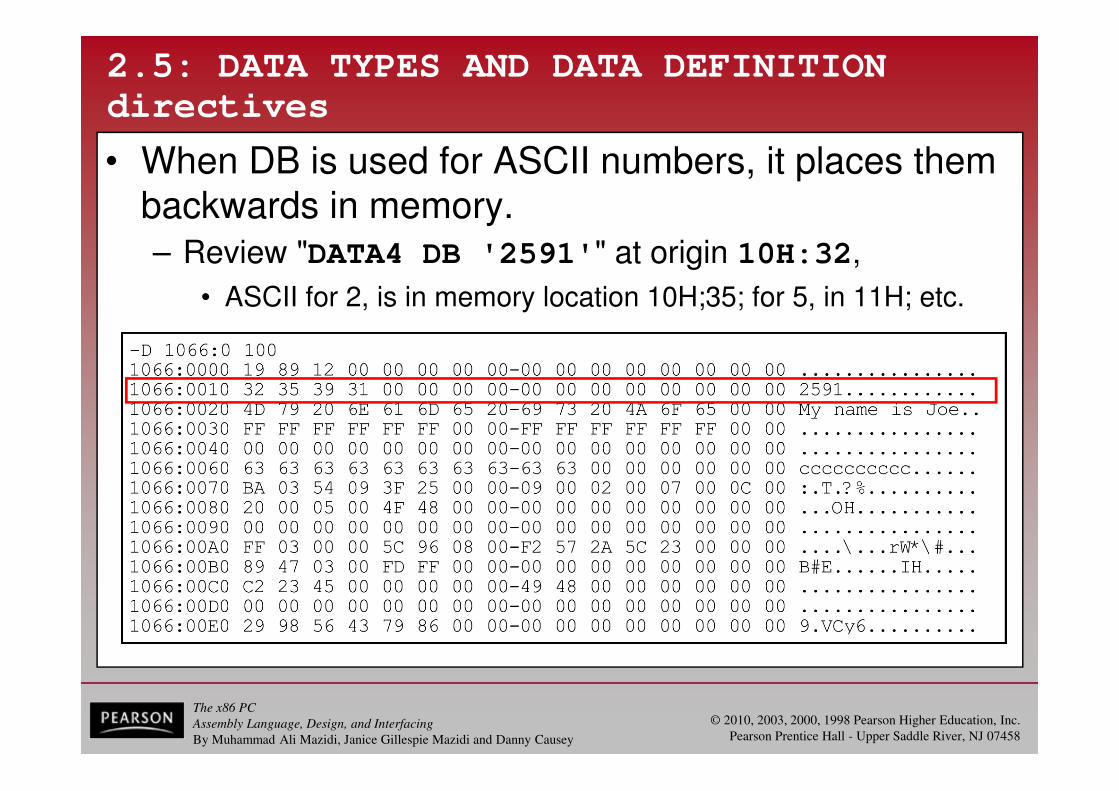
• When DB is used for ASCII numbers, it places them backwards in memory. – Review "DATA4 DB '2591'" at origin 10H:32,
• ASCII for 2, is in memory location 10H;35; for 5, in 11H; etc.

The x86 PC
Assembly Language, Design, and Interfacing
By Muhammad Ali Mazidi, Janice Gillespie Mazidi and Danny Causey
© 2010, 2003, 2000, 1998 Pearson Higher Education, Inc.
Pearson Prentice Hall - Upper Saddle River, NJ 07458
2.6: FULL SEGMENT DEFINITION
segment definition
• The SEGMENT and ENDS directives indicate the beginning &ending of a segment, in this format:
– The label, or name, must follow naming conventions and be unique.
• The [options] field gives important information to the
assembler for organizing the segment, but is not required.
– The ENDS label must be the same label as in the SEGMENT directive.
• In full segment definition, the ".MODEL" directive is not used.

The x86 PC
Assembly Language, Design, and Interfacing
By Muhammad Ali Mazidi, Janice Gillespie Mazidi and Danny Causey
© 2010, 2003, 2000, 1998 Pearson Higher Education, Inc.
Pearson Prentice Hall - Upper Saddle River, NJ 07458
2.6: FULL SEGMENT DEFINITION
segment definition
• The directives ".STACK", ".DATA", and ".CODE" are
replaced by SEGMENT and ENDS directives that surround each segment.
– Figure 2-8 shows the full segment definition andsimplified format, side by side.
• Followed by programs 2-2 and 2-3.

The x86 PC
Assembly Language, Design, and Interfacing
By Muhammad Ali Mazidi, Janice Gillespie Mazidi and Danny Causey
© 2010, 2003, 2000, 1998 Pearson Higher Education, Inc.
Pearson Prentice Hall - Upper Saddle River, NJ 07458
2.6: FULL SEGMENT DEFINITION
segment definition
Figure 2-8
The x86 PC
Assembly Language, Design, and Interfacing
By Muhammad Ali Mazidi, Janice Gillespie Mazidi and Danny Causey
© 2010, 2003, 2000, 1998 Pearson Higher Education, Inc.
Pearson Prentice Hall - Upper Saddle River, NJ 07458
2.6: FULL SEGMENT DEFINITION
segment definition
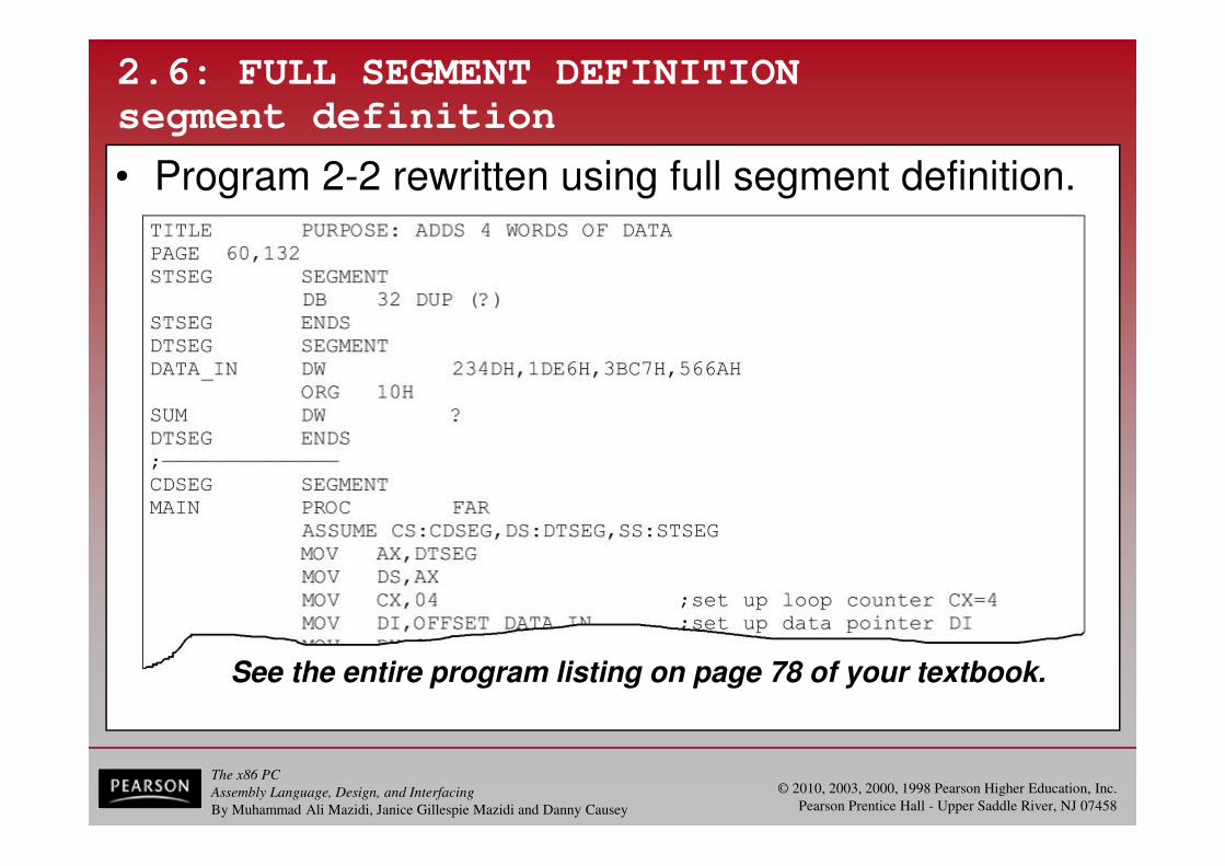
• Program 2-2 rewritten using full segment definition.
See the entire program listing on page 78 of your textbook.

The x86 PC
Assembly Language, Design, and Interfacing
By Muhammad Ali Mazidi, Janice Gillespie Mazidi and Danny Causey
© 2010, 2003, 2000, 1998 Pearson Higher Education, Inc.
Pearson Prentice Hall - Upper Saddle River, NJ 07458
2.6: FULL SEGMENT DEFINITION
segment definition
• Program 2-3 rewritten using full segment definition.
See the entire program listing on page 79 of your textbook.

The x86 PC
Assembly Language, Design, and Interfacing
By Muhammad Ali Mazidi, Janice Gillespie Mazidi and Danny Causey
© 2010, 2003, 2000, 1998 Pearson Higher Education, Inc.
Pearson Prentice Hall - Upper Saddle River, NJ 07458
2.6: FULL SEGMENT DEFINITION
stack segment definition
• The stack segment shown contains the line "DB 64 DUP (?)" to reserve 64 bytes of memory
for the stack.
– The following three lines in full segment definition are comparable to ".STACK 64" in simple definition:
• The stack segment shown contains the line "DB 64 DUP (?)" to reserve 64 bytes of memory
for the stack.
– The following three lines in full segment definition are comparable to ".STACK 64" in simple definition:
The x86 PC
Assembly Language, Design, and Interfacing
By Muhammad Ali Mazidi, Janice Gillespie Mazidi and Danny Causey
© 2010, 2003, 2000, 1998 Pearson Higher Education, Inc.
Pearson Prentice Hall - Upper Saddle River, NJ 07458
2.6: FULL SEGMENT DEFINITION
data segment definition
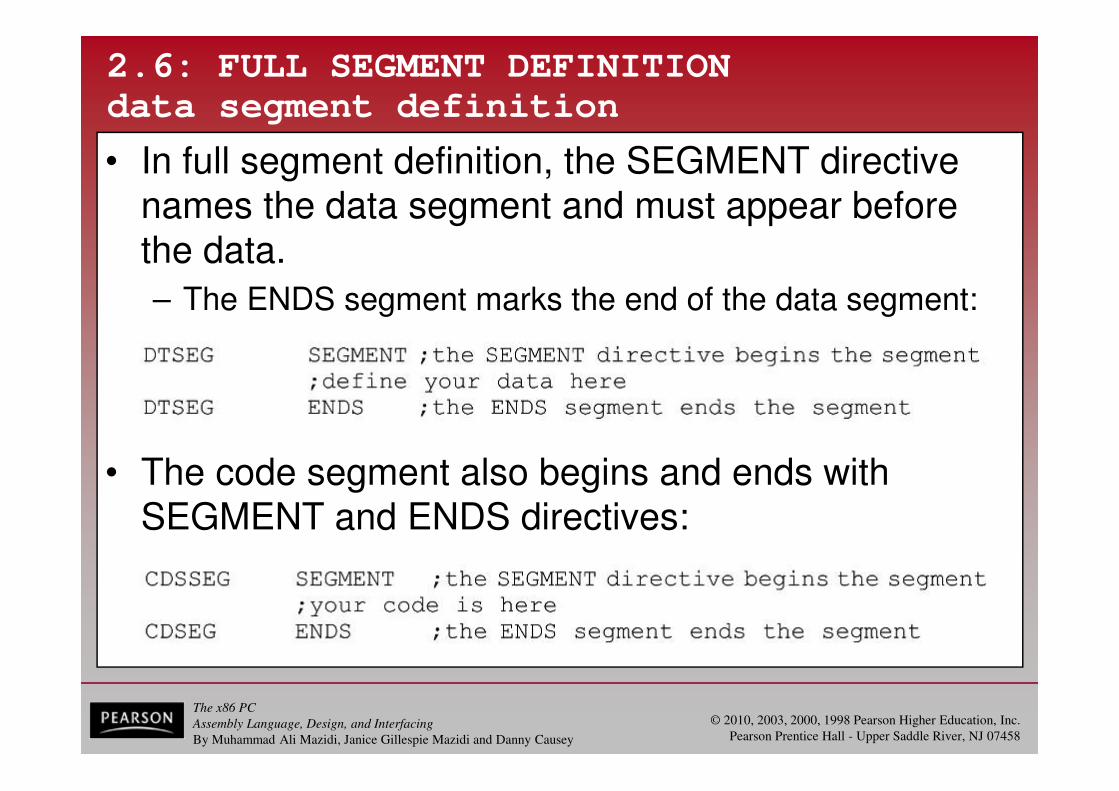
• In full segment definition, the SEGMENT directive names the data segment and must appear before the data.
– The ENDS segment marks the end of the data segment:
• The code segment also begins and ends with SEGMENT and ENDS directives:

The x86 PC
Assembly Language, Design, and Interfacing
By Muhammad Ali Mazidi, Janice Gillespie Mazidi and Danny Causey
© 2010, 2003, 2000, 1998 Pearson Higher Education, Inc.
Pearson Prentice Hall - Upper Saddle River, NJ 07458
2.6: FULL SEGMENT DEFINITION
code segment definition
• Immediately after PROC, the ASSUME directive, associates segments with specific registers.
– By assuming the segment register is equal to the segment labels used in the program.
• If an extra segment had been used, ES wouldalso be included in the ASSUME statement.
– ASSUME tells the assembler which of the segments, defined by SEGMENT, should be used.
• Also helps the assembler to calculate the offsetaddresses from the beginning of that segment.
• In "MOV AL, [BX] " the BX register is the offset of
the data segment.

The x86 PC
Assembly Language, Design, and Interfacing
By Muhammad Ali Mazidi, Janice Gillespie Mazidi and Danny Causey
© 2010, 2003, 2000, 1998 Pearson Higher Education, Inc.
Pearson Prentice Hall - Upper Saddle River, NJ 07458
2.6: FULL SEGMENT DEFINITION
code segment definition
• On transfer of control from OS to the program, ofthe three segment registers, only CS and SS have the proper values.
– The DS value (and ES) must be initialized by the program.
The x86 PC
Assembly Language, Design, and Interfacing
By Muhammad Ali Mazidi, Janice Gillespie Mazidi and Danny Causey
© 2010, 2003, 2000, 1998 Pearson Higher Education, Inc.
Pearson Prentice Hall - Upper Saddle River, NJ 07458
2.6: FULL SEGMENT DEFINITION
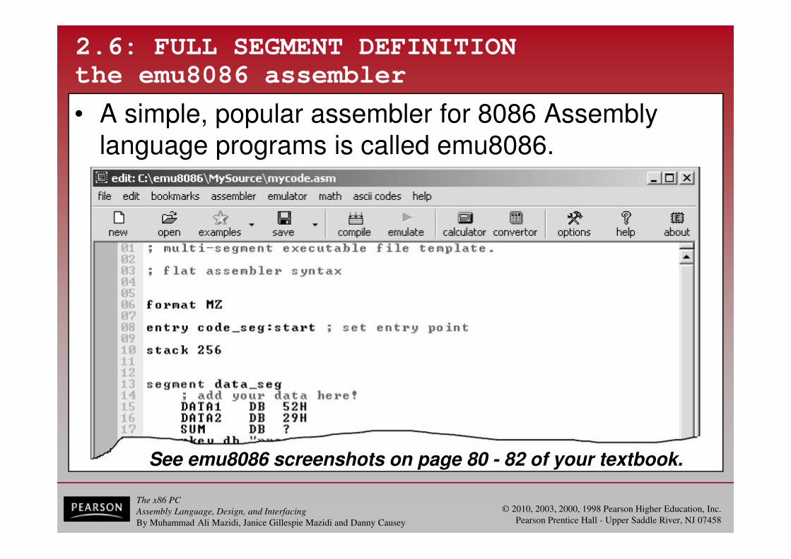
the emu8086 assembler
• A simple, popular assembler for 8086 Assembly language programs is called emu8086.
See emu8086 screenshots on page 80 - 82 of your textbook.

The x86 PC
Assembly Language, Design, and Interfacing
By Muhammad Ali Mazidi, Janice Gillespie Mazidi and Danny Causey
© 2010, 2003, 2000, 1998 Pearson Higher Education, Inc.
Pearson Prentice Hall - Upper Saddle River, NJ 07458
2.6: FULL SEGMENT DEFINITION
the emu8086 assembler
Download the emu8086assembler from this website:
http://www.emu8086.com
See a Tutorial on how to use it at:
http://www.MicroDigitalEd.com
The x86 PC
Assembly Language, Design, and Interfacing
By Muhammad Ali Mazidi, Janice Gillespie Mazidi and Danny Causey
© 2010, 2003, 2000, 1998 Pearson Higher Education, Inc.
Pearson Prentice Hall - Upper Saddle River, NJ 07458
2.6: FULL SEGMENT DEFINITION
EXE vs. COM files
• The EXE file is used widely as it can be of any size.
– There are occasions when, due to a limited amount of memory, one needs to have very compact code.
• COM files must fit in a single segment.
– The x86 segment size is 64K bytes, thus the COM file cannot be larger than 64K.
• To limit the size to 64K requires defining the data inside the code segment and using the end areaof the code segment for the stack.
– In contrast to the EXE file, the COM file has no separate data segment definition.

The x86 PC
Assembly Language, Design, and Interfacing
By Muhammad Ali Mazidi, Janice Gillespie Mazidi and Danny Causey
© 2010, 2003, 2000, 1998 Pearson Higher Education, Inc.
Pearson Prentice Hall - Upper Saddle River, NJ 07458
2.6: FULL SEGMENT DEFINITION
EXE vs. COM files
• The header block, which occupies 512 bytes of memory, precedes every EXE file.
– It contains information such as size, address locationin memory, and stack address of the EXE module.
– The COM file does not have a header block.

The x86 PC
Assembly Language, Design, and Interfacing
By Muhammad Ali Mazidi, Janice Gillespie Mazidi and Danny Causey
© 2010, 2003, 2000, 1998 Pearson Higher Education, Inc.
Pearson Prentice Hall - Upper Saddle River, NJ 07458
2.7: FLOWCHARTS AND PSEUDOCODE
structured programming
• Structured programming uses three basic typesof program control structures:
– Sequence.
– Control.
– Iteration.

The x86 PC
Assembly Language, Design, and Interfacing
By Muhammad Ali Mazidi, Janice Gillespie Mazidi and Danny Causey
© 2010, 2003, 2000, 1998 Pearson Higher Education, Inc.
Pearson Prentice Hall - Upper Saddle River, NJ 07458
2.7: FLOWCHARTS AND PSEUDOCODE
structured programming
• Principles a structured program should follow:
– The program should be designed before it is coded.
• By using flowcharting or pseudocode, the design is clearthose coding, as well as those maintaining the program later.
– Use comments within the program and documentation.
• This will help other figure out what the program doesand how it does it.
– The main routine should consist primarily of calls to subroutines that perform the work of the program.
• Sometimes called top-down programming.
• Using subroutines to accomplish repetitive tasks savestime in coding, and makes the program easier to read.

The x86 PC
Assembly Language, Design, and Interfacing
By Muhammad Ali Mazidi, Janice Gillespie Mazidi and Danny Causey
© 2010, 2003, 2000, 1998 Pearson Higher Education, Inc.
Pearson Prentice Hall - Upper Saddle River, NJ 07458
2.7: FLOWCHARTS AND PSEUDOCODE
• Principles a structured program should follow:
– Data control is very important.
• The programmer should document the purpose of each variable, and which subroutines might alter its value.
• Each subroutine should document its input/output variables, and which input variables might be altered within it.
The x86 PC
Assembly Language, Design, and Interfacing
By Muhammad Ali Mazidi, Janice Gillespie Mazidi and Danny Causey
© 2010, 2003, 2000, 1998 Pearson Higher Education, Inc.
Pearson Prentice Hall - Upper Saddle River, NJ 07458
2.7: FLOWCHARTS AND PSEUDOCODE
flowcharts
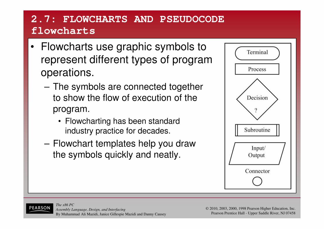
• Flowcharts use graphic symbols to represent different types of program operations.
– The symbols are connected togetherto show the flow of execution of the program.
• Flowcharting has been standardindustry practice for decades.
– Flowchart templates help you drawthe symbols quickly and neatly.

The x86 PC
Assembly Language, Design, and Interfacing
By Muhammad Ali Mazidi, Janice Gillespie Mazidi and Danny Causey
© 2010, 2003, 2000, 1998 Pearson Higher Education, Inc.
Pearson Prentice Hall - Upper Saddle River, NJ 07458
2.7: FLOWCHARTS AND PSEUDOCODE
pseudocode
• An alternative to flowcharts, pseudocode, involves writing brief descriptions of the flow of the code.
– SEQUENCE is executing instructions one after the other.
Figure 2-15SEQUENCEPseudocode vs. Flowchart

The x86 PC
Assembly Language, Design, and Interfacing
By Muhammad Ali Mazidi, Janice Gillespie Mazidi and Danny Causey
© 2010, 2003, 2000, 1998 Pearson Higher Education, Inc.
Pearson Prentice Hall - Upper Saddle River, NJ 07458
2.7: FLOWCHARTS AND PSEUDOCODE
pseudocode
• An alternative to flowcharts, pseudocode, involves writing brief descriptions of the flow of the code.
– IF-THEN-ELSE and IF-THEN are control programming structures, which can indicate one statement or a groupof statements.
Figure 2-16IF-THEN-ELSEPseudocode vs. Flowchart

The x86 PC
Assembly Language, Design, and Interfacing
By Muhammad Ali Mazidi, Janice Gillespie Mazidi and Danny Causey
© 2010, 2003, 2000, 1998 Pearson Higher Education, Inc.
Pearson Prentice Hall - Upper Saddle River, NJ 07458
2.7: FLOWCHARTS AND PSEUDOCODE
pseudocode
• An alternative to flowcharts, pseudocode, involves writing brief descriptions of the flow of the code.
– IF-THEN-ELSE and IF-THEN are control programming structures, which can indicate one statement or a groupof statements.
Figure 2-17IF-THENPseudocode vs. Flowchart
The x86 PC
Assembly Language, Design, and Interfacing
By Muhammad Ali Mazidi, Janice Gillespie Mazidi and Danny Causey
© 2010, 2003, 2000, 1998 Pearson Higher Education, Inc.
Pearson Prentice Hall - Upper Saddle River, NJ 07458
2.7: FLOWCHARTS AND PSEUDOCODE
pseudocode
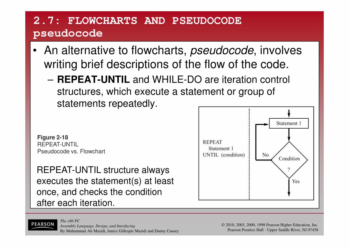
• An alternative to flowcharts, pseudocode, involves writing brief descriptions of the flow of the code.
– REPEAT-UNTIL and WHILE-DO are iteration control structures, which execute a statement or group of statements repeatedly.
Figure 2-18REPEAT-UNTILPseudocode vs. Flowchart
REPEAT-UNTIL structure alwaysexecutes the statement(s) at leastonce, and checks the conditionafter each iteration.

The x86 PC
Assembly Language, Design, and Interfacing
By Muhammad Ali Mazidi, Janice Gillespie Mazidi and Danny Causey
© 2010, 2003, 2000, 1998 Pearson Higher Education, Inc.
Pearson Prentice Hall - Upper Saddle River, NJ 07458
2.7: FLOWCHARTS AND PSEUDOCODE
pseudocode
• An alternative to flowcharts, pseudocode, involves writing brief descriptions of the flow of the code.
– REPEAT-UNTIL and WHILE-DO are iteration control structures, which execute a statement or group of statements repeatedly.
Figure 2-19WHILE-DOPseudocode vs. Flowchart
WHILE-DO may not execute thestatement(s) at all, as the conditionis checked at the beginning ofeach iteration.

The x86 PC
Assembly Language, Design, and Interfacing
By Muhammad Ali Mazidi, Janice Gillespie Mazidi and Danny Causey
© 2010, 2003, 2000, 1998 Pearson Higher Education, Inc.
Pearson Prentice Hall - Upper Saddle River, NJ 07458
2.7: FLOWCHARTS AND PSEUDOCODE
control structures
Flowchart vs. pseudocode for Program 2-1, showing steps for initializing/decrementing counters.
Housekeeping, such as initializing the data segment register in the MAIN procedure are not included in the flowchart or pseudocode.

The x86 PC
Assembly Language, Design, and Interfacing
By Muhammad Ali Mazidi, Janice Gillespie Mazidi and Danny Causey
© 2010, 2003, 2000, 1998 Pearson Higher Education, Inc.
Pearson Prentice Hall - Upper Saddle River, NJ 07458
2.7: FLOWCHARTS AND PSEUDOCODE
control structures
• The purpose of flowcharts or pseudocode is to show the program flow, and what the program does.
– Pseudocode gives the same information as a flowchart,in a more compact form.
• Often written in layers, in a top-down manner.
– Code specific to a certain language or operating platformis not described in the pseudocode or flowchart.
• Ideally, one could take a flowchart or pseudocodeand code the program in any language.
The x86 PC
Assembly Language, Design, and Interfacing
By Muhammad Ali Mazidi, Janice Gillespie Mazidi and Danny Causey
© 2010, 2003, 2000, 1998 Pearson Higher Education, Inc.
Pearson Prentice Hall - Upper Saddle River, NJ 07458
ENDS ; TWO
Dec Hex Bin
2 2 00000010