MP-24 Wireless Bridge/ROuter - dcbnet.com · Chapter 1 Introduction ... This Quick-Start Guide...
17
MP-Series Wireless Bridge/Router Product Family Quick-Start Manual Revised March, 2009 Manual Version 1.1, Firmware 5.10
Transcript of MP-24 Wireless Bridge/ROuter - dcbnet.com · Chapter 1 Introduction ... This Quick-Start Guide...
MP-Series
Wireless Bridge/Router
Product FamilyQuick-Start Manual
Revised March, 2009
Manual Version 1.1, Firmware 5.10
FCC StatementThis device complies with the limits for a Class A digital device, pursuant to Part 15 of the FCC rules.
This equipment has been tested and found to comply with the limits for a Class A digital device pursuant to Part 15 of the FCC Rules. These limits are designed to provide reasonable protection against harmful interference when the equipment is operated in a commercial environment. This equipment generates, uses, and can radiate radio frequency energy and if not installed and used in accordance with the instruction manual may cause harmful interference to radio communications.
Operation of this equipment in a residential area is likely to cause harmful interference, in which case the user will be required to correct the interference at the user's own expense.
CE Mark Warning
This is a class B product. In a domestic environment this product may cause radio interference in which case the user may be required to take adequate measures.
Copyright 2007, 2009 All rights reserved.
Manual version 1.1, Firmware version 5.10
All trademarks and trade names are the properties of their respective owners.
i
TABLE OF CONTENTS
Chapter 1Introduction............................................................................................1
Other Features................................................................................................2Easy Configuration using KarlNet/Terabeam Configurator Software..........2
Point-to-Point and Point-to-MultiPoint Operation.........................................2
On-board Tools..................................................................................................2
.......................................................................................................................2
Package Contents...........................................................................................2Software Requirements..................................................................................2
Chapter 2Installation..............................................................................................3
Overview...................................................................................................3Karlnet/Terabeam Configurator Program ..............................................3Help Screens and Field Edits...................................................................3
Installation and Configuration......................................................................31. Install the Karlnet/Terabeam software on a PC ......................................3
2. Connect the MP-24 and Workstation PC to the same LAN....................3
3. Start the configurator software.................................................................3
4. Select a device to configure........................................................................3
5. Enter the device password.........................................................................4
6. Open the General Setup window...............................................................4
7. Open the Interface Setup window.............................................................4
8. Configure the IEEE 802.11 interface .......................................................5
9. IEEE 802.11 Interface Advanced Setup..................................................6
10. Configure 802.11 Security.......................................................................6
11. IP Host Setup...........................................................................................7
12. Save the Config file for the MP-24..........................................................7
13. Complete the setup and test the link......................................................7
Chapter 3Configuration.........................................................................................8
Overview.........................................................................................................8Monitor/Configuration Help...........................................................................9
Analyze Tab Menu..........................................................................................11
Link Test.........................................................................................................12
ii

Introduction
Appendix ASpecifications..........................................................................................13
MP-24 Wireless Bridge Router Specifications........................................13
iii
Chapter 1
IntroductionThis chapter provides an overview of features and capabilities.
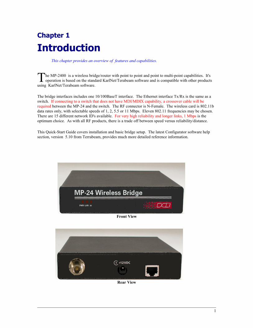
he MP-2400 is a wireless bridge/router with point to point and point to multi-point capabilities. It's operation is based on the standard KarlNet/Terabeam software and is compatible with other products
using KarlNet/Terabeam software.TThe bridge interfaces includes one 10/100BaseT interface. The Ethernet interface Tx/Rx is the same as a switch. If connecting to a switch that does not have MDI/MDIX capability, a crossover cable will be required between the MP-24 and the switch. The RF connector is N-Female. The wireless card is 802.11b data rates only, with selectable speeds of 1, 2, 5.5 or 11 Mbps. Eleven 802.11 frequencies may be chosen. There are 15 different network ID's available. For very high reliability and longer links, 1 Mbps is the optimum choice. As with all RF products, there is a trade off between speed versus reliability/distance.
This Quick-Start Guide covers installation and basic bridge setup. The latest Configurator software help section, version 5.10 from Terrabeam, provides much more detailed reference information.
Front View
Rear View
1

Other Features
Easy Configuration using KarlNet /Terabeam Configurator SoftwareThe KarlNet/Terabeam Configuration software has an easy-to-use graphical interface. Selections are made using radio buttons, check boxes and simple fill-in-the-blank boxes.
Compatibility
The MP-24 is operationally compatible with other KarlNet/Terabeam based wireless bridges. This allows the MP-24 to inter-operate with an existing system.
Point-to-Point and Point-to-MultiPoint Operation
The MP-24 may be used in either Point-to-Point or Multi-Point networks.
On-board Tools
The MP-24 contains numerous performance measurement and diagnostic tools. See the “Monitor”, “Analyze Tab” and “Link Test” section of this manual for information on how to access,use and find additional details about these tools.
TurboCell Polling Technology
The MP-24 uses TurboCell polling to improve upon standard 802.11 protocols. TurboCell polling is adaptive and dynamic, allowing for greater throughput than standard 802.11. Packet sizes and polling intervals are dynamically changed to optimize throughput. Please refer to the Configurator Help section for in depth details of how TurboCell operates.
Package Contents
You should find the following items packaged with your MP-24 Bridge:
• The MP-24 hardware
• Power Adapter (if 120VAC powered)
• This User’s Guide / Configurator CDROM
If any of the above are missing, contact your dealer immediately.
Software Requirements
The MP-24 can be configured as a bridge only or can route IP data. This quick start guide covers bridge setup. Routing details are found in the Configurator Help pages. The MP-24 support both direct routing to IP LANS directly connected to the MP-24, and indirect routing, where an external router is used to relay the data to other IP networks. The bridge function supports IP and associated protocols such as UDP, ICMP, DHCP, etc, and any protocol built upon IP or TCP/IP.
KarlNet/Terabeam Configurator software (supplied with the unit) is required for configuration. The KarlNet Configurator requires the Windows operating system.
2
Configuration
Chapter 2
InstallationThis Chapter details the installation process .
OverviewInstallation and configuration of the MP-24 ranges from a simple set up for a simple bridge-to-bridge link, to complicated configurations for a wireless link that includes routing, filtering, multi-point operation, and other advanced features. Always begin with a simple bridge link to verify link operation before adding advanced features.
Karlnet/Terabeam Configurator Program The Karlnet/Terabeam Configurator program is used to configure the MP-24. This configuration program must be installed on a Windows PC prior to configuring the MP-24.
Help Screens and Field EditsThere is a very detailed help system available within the Configurator. Please consult the “Help” for more detailed information specific to your particular application and special system requirements. This manual covers the TurboCell Base Station and Satellite setup.
Installation and Sample Configuration for Bridging
1. Install the Karlnet software on a PC
Install the Karlnet/Terabeam Configurator software on a Windows workstation connected to the LAN. The Configurator automatically appears as a shortcut on your desktop.
2. Connect the MP-24 and Workstation PC to the same LAN
Configuration is performed using the Karlnet/Terabeam Configurator software via the LAN. Connect the MP-24 to the LAN with the workstation.
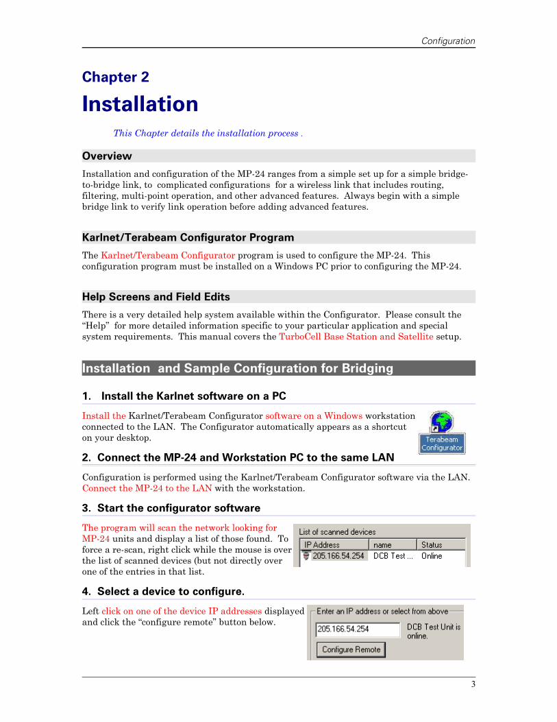
3. Start the configurator software
The program will scan the network looking for MP-24 units and display a list of those found. To force a re-scan, right click while the mouse is over the list of scanned devices (but not directly over one of the entries in that list.
4. Select a device to configure.
Left click on one of the device IP addresses displayed and click the “configure remote” button below.
3
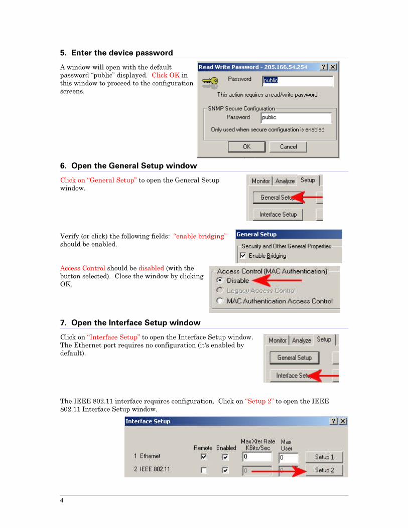
5. Enter the device password
A window will open with the default password “public” displayed. Click OK in this window to proceed to the configuration screens.
6. Open the General Setup window
Click on “General Setup” to open the General Setup window.
Verify (or click) the following fields: “enable bridging” should be enabled.
Access Control should be disabled (with the button selected). Close the window by clicking OK.
7. Open the Interface Setup window
Click on “Interface Setup” to open the Interface Setup window. The Ethernet port requires no configuration (it's enabled by default).
The IEEE 802.11 interface requires configuration. Click on “Setup 2” to open the IEEE 802.11 Interface Setup window.
4

Configuration
8. Configure the IEEE 802.11 interface
The “IEEE 802.11 Interface Setup” window will open.
1. In the “Mode Selection” section, select either “TurboCell Base Station” or “TurboCell Satellite Station”, depending upon which the unit should be.
2. If “TurboCell Base Station” was selected, another section “TurboCell Base Station Mode” will become enabled.
3. Select “Polling Base Station” on that section. Click on “Advanced”
9. IEEE 802.11 Interface Advanced Setup
In the “Radio Transmit Rate” section, select a frequency channel and transmit rate.
5

1. Select a frequency channel (1-11) that matches the other units in the system. There are three non-overlapping channels available (1,6, and 11) if multiple systems are used near each other.
2. Select the transmit rate desired (1, 2, 5.5, 11 Mbps), noting that the faster rates are more appropriate for shorter ranges, and lower rates provide better reliability at greater distances.
3. In the “Network Settings” section, select a network ID (1 to 15) that matches other units in the system. If desired, specify a bandwidth limit for the satellite in the “Bandwidth Control” section. Exit the screen by clicking on OK.
10. Configure 802.11 Security
From the IEEE 802.11 Interface Setup window, click on “Security”. The 802.11 Security screen displays. Disable WEP security or configure WEP to match the other units in the system. Click OK to exit the screen. Exit all configuration windows back to the main configuration screen by clicking OK on each open window.
11. IP Host Setup
From the main window, select the IP Host button.
Within this window, either select DHCP or specify an IP address. When using the MP-24 in Bridge mode, the IP address is used only for managing the unit or SNMP reporting. The Default TTL at the
6
Configuration
bottom of the IP Setup box can be left at the default value of 255. Check the Configuration Help section if more information on the TTL selection is desired. Exit the window by clicking OK.
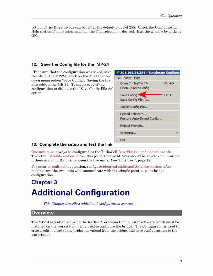
12. Save the Config file for the MP-24
To insure that the configuration was saved, save the file for the MP-24. Click on the File tab drop down menu option “Save Config”. Saving the file also reboots the MR-24. To save a copy of the configuration to disk, use the “Save Config File As” option.
13. Complete the setup and test the link
One unit must always be configured as the TurboCell Base Station, and one unit as the TurboCell Satellite station. From this point, the two MP-24s should be able to communicate if there is a valid RF link between the two units. See “Link Test”, page 12.
For point-to-multipoint operation, configure identical additional Satellite stations after making sure the two units will communicate with this simple point-to-point bridge configuration.
Chapter 3
Additional ConfigurationThis Chapter describes additional configuration screens.
Overview
The MP-24 is configured using the KarlNet/Terabeam Configurator software which must be installed on the workstation being used to configure the bridge. The Configurator is used to create, edit, upload to the bridge, download from the bridge, and save configurations to the workstation.
7

The Configurator software includes a comprehensive help screen system accessible from the “Help” tab.
Main Help Screen
Note that some screens are model specific, and some models do not contain all screens shown.
For example, under the “Analyze” tab, “Wireless Scan” is not implemented in the MP-24. In the Configuration Help, the help screen shows “TBD”. This function in not implemented.
8
Configuration
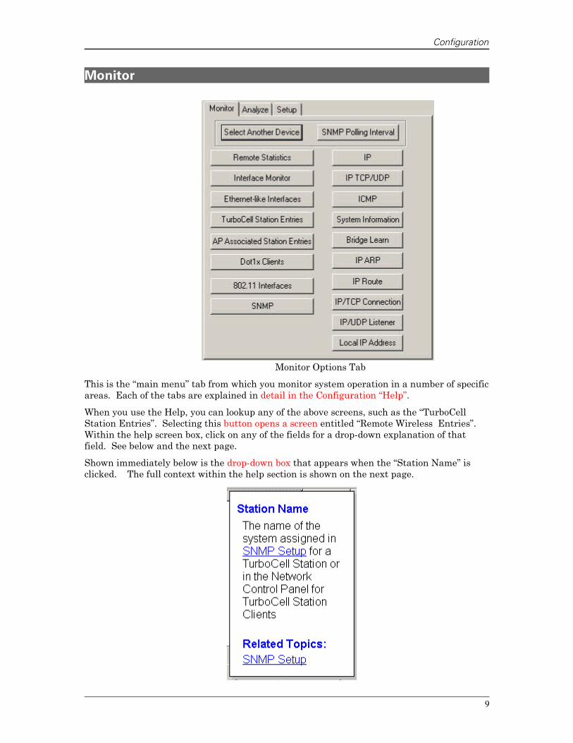
Monitor
Monitor Options Tab
This is the “main menu” tab from which you monitor system operation in a number of specific areas. Each of the tabs are explained in detail in the Configuration “Help”.
When you use the Help, you can lookup any of the above screens, such as the “TurboCell Station Entries”. Selecting this button opens a screen entitled “Remote Wireless Entries”. Within the help screen box, click on any of the fields for a drop-down explanation of that field. See below and the next page.
Shown immediately below is the drop-down box that appears when the “Station Name” is clicked. The full context within the help section is shown on the next page.
9

Below is the Configuration Help screen that shows the drop down box in the full context of the Help. To view the selection shown below, Configuration Help was opened. Then “Remote Wireless Entries” was selected. This opened up the “Remote Wireless Entries -Overview”.
Clicking on the “Station Name” opened the drop-down box.
10
Configuration
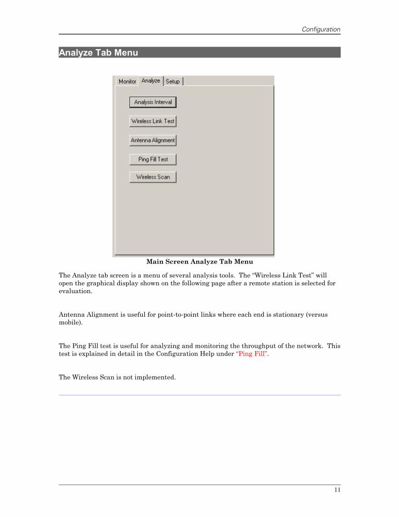
Analyze Tab Menu
Main Screen Analyze Tab Menu
The Analyze tab screen is a menu of several analysis tools. The “Wireless Link Test” will open the graphical display shown on the following page after a remote station is selected for evaluation.
Antenna Alignment is useful for point-to-point links where each end is stationary (versus mobile).
The Ping Fill test is useful for analyzing and monitoring the throughput of the network. This test is explained in detail in the Configuration Help under “Ping Fill”.
The Wireless Scan is not implemented.
11
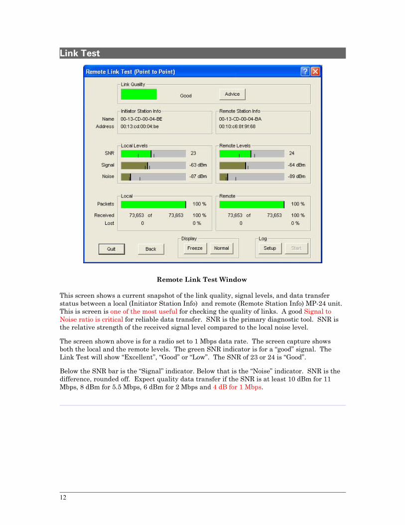
Link Test
Remote Link Test Window
This screen shows a current snapshot of the link quality, signal levels, and data transfer status between a local (Initiator Station Info) and remote (Remote Station Info) MP-24 unit. This is screen is one of the most useful for checking the quality of links. A good Signal to Noise ratio is critical for reliable data transfer. SNR is the primary diagnostic tool. SNR is the relative strength of the received signal level compared to the local noise level.
The screen shown above is for a radio set to 1 Mbps data rate. The screen capture shows both the local and the remote levels. The green SNR indicator is for a “good” signal. The Link Test will show “Excellent”, “Good” or “Low”. The SNR of 23 or 24 is “Good”.
Below the SNR bar is the “Signal” indicator. Below that is the “Noise” indicator. SNR is the difference, rounded off. Expect quality data transfer if the SNR is at least 10 dBm for 11 Mbps, 8 dBm for 5.5 Mbps, 6 dBm for 2 Mbps and 4 dB for 1 Mbps.
12
Appendix A
Specifications MP-24 Wireless Bridge Router Specifications
• Power Input: 12VDC 4 watts, normally supplied by 120VAC wall-mounted power supply or POE (POE 802.3af compatible)
• Temperature -40 to +65 C
• Size: 7 ¼” x 7” x 1 ¾” excluding “N” connector
• LAN Interface: 10 BaseT Auto Duplex, node interface, requires straight through Ethernet cable to a switch if the switch does not support MDI/MDIX
• Antenna Interface: Type “N” female bulkhead connector
• Radio Receive Sensitivity -83 dBm at 11Mbps, -87 dBm at 1 Mbps
• LED (LAN Activity, Radio Activity, Power )
• Stand alone package
• Connection uses KarlNet/Terabeam software
• Data Rate: 1 M, 2 M, 5.5 M, 11 Mbps
• Default IP address: LAN: 192.168.0.1
• Data transport as 802.11 AP, 802.11 client (Super Ethernet Convertor), TurboCell No Base Stations, TurboCell Base Station, TurboCell Satellite Station mode. See Configurator Help for more details.
• Security: WEP, frequency selection, data mode, i.e. TurboCell proprietary polling mode, network channel selection, TurboCell Access List, Protocol Filtering, MAC filtering.
13