MOW227 2014 FASTENERS 2 - Varsity Field · • Turn the nut not the bolt if possible. ... typical...
41
Department of Mechanical and Aeronautical Engineering SCREWS, FASTENERS AND NON PERMANENT JOINTS 2 MOW 227 2014
Transcript of MOW227 2014 FASTENERS 2 - Varsity Field · • Turn the nut not the bolt if possible. ... typical...
Department of Mechanical and Aeronautical Engineering
SCREWS, FASTENERS AND NON
PERMANENT JOINTS
2
MOW 227 2014
Department of Mechanical and Aeronautical Engineering
Department of Mechanical and Aeronautical Engineering
Department of Mechanical and Aeronautical Engineering
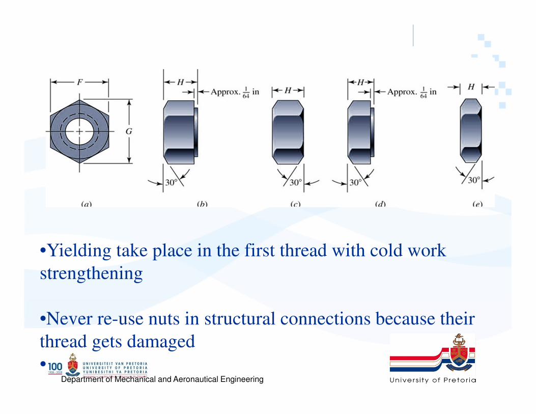
•Yielding take place in the first thread with cold work
strengthening
•Never re-use nuts in structural connections because their
thread gets damaged
•

Department of Mechanical and Aeronautical Engineering
• Washers underneath bolt head
• Purpose of a bolt is to clamp two or more parts
together
• Turn the nut not the bolt if possible. Why?

Department of Mechanical and Aeronautical Engineering
countersunk
Department of Mechanical and Aeronautical Engineering

Department of Mechanical and Aeronautical Engineering
h
t2
BOLTED JOINTS STIFFNESS
ll`
Table 8.7

Department of Mechanical and Aeronautical Engineering
BOLT STIFFNESS
Tensile Stress Area

Department of Mechanical and Aeronautical Engineering
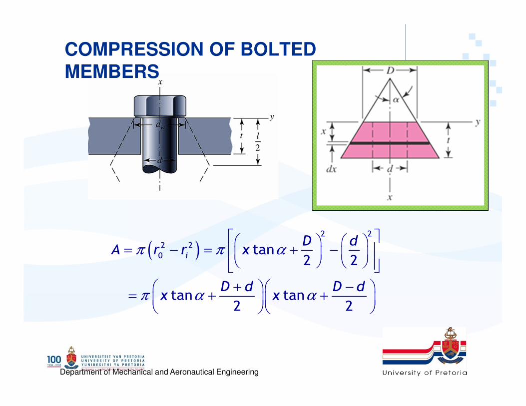
COMPRESSION OF BOLTED MEMBERS
• There may be more than two members in the grip of
the bolt
• The total member stiffness of the joint
– If one of the members is a gasket the stiffness is
so soft relative to the other members that for all
practical purpose, the others can be neglected
and only the gasket used
nm kkkkk
11111
321
++++= L

Department of Mechanical and Aeronautical Engineering
m
kd
kt

Department of Mechanical and Aeronautical Engineering
Department of Mechanical and Aeronautical Engineering
COMPRESSION OF BOLTED
MEMBERS
( )2 2
2 2
0tan
2 2
tan tan2 2
i
D dA r r x
D d D dx x
π π α
π α α
= − = + −
+ − = + +
Department of Mechanical and Aeronautical Engineering
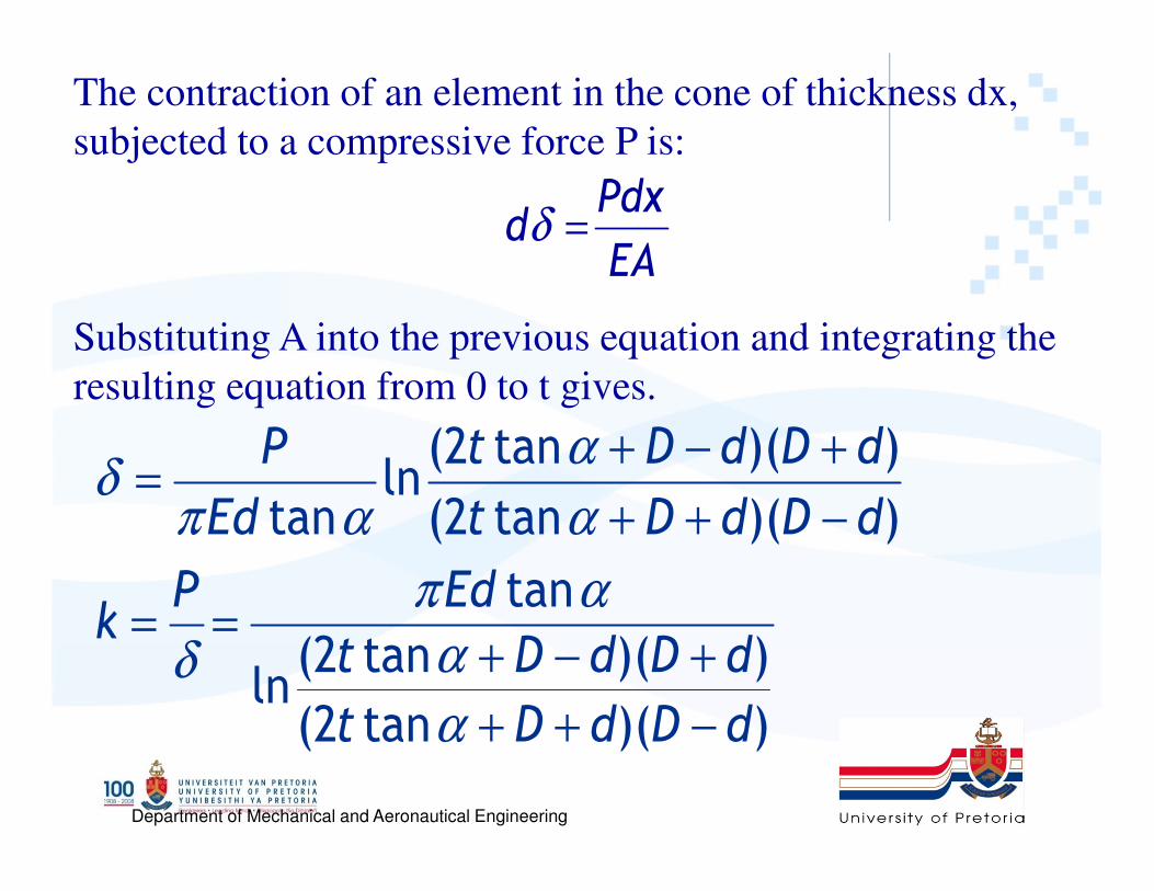
(2 tan )( )ln
tan (2 tan )( )
tan
(2 tan )( )ln(2 tan )( )
P t D d D d
Ed t D d D d
P Edk
t D d D d
t D d D d
αδ
π α α
π α
αδ
α
+ − +=
+ + −
= =+ − +
+ + −
The contraction of an element in the cone of thickness dx,
subjected to a compressive force P is:
Substituting A into the previous equation and integrating the
resulting equation from 0 to t gives.
Pdxd
EAδ =
Department of Mechanical and Aeronautical Engineering
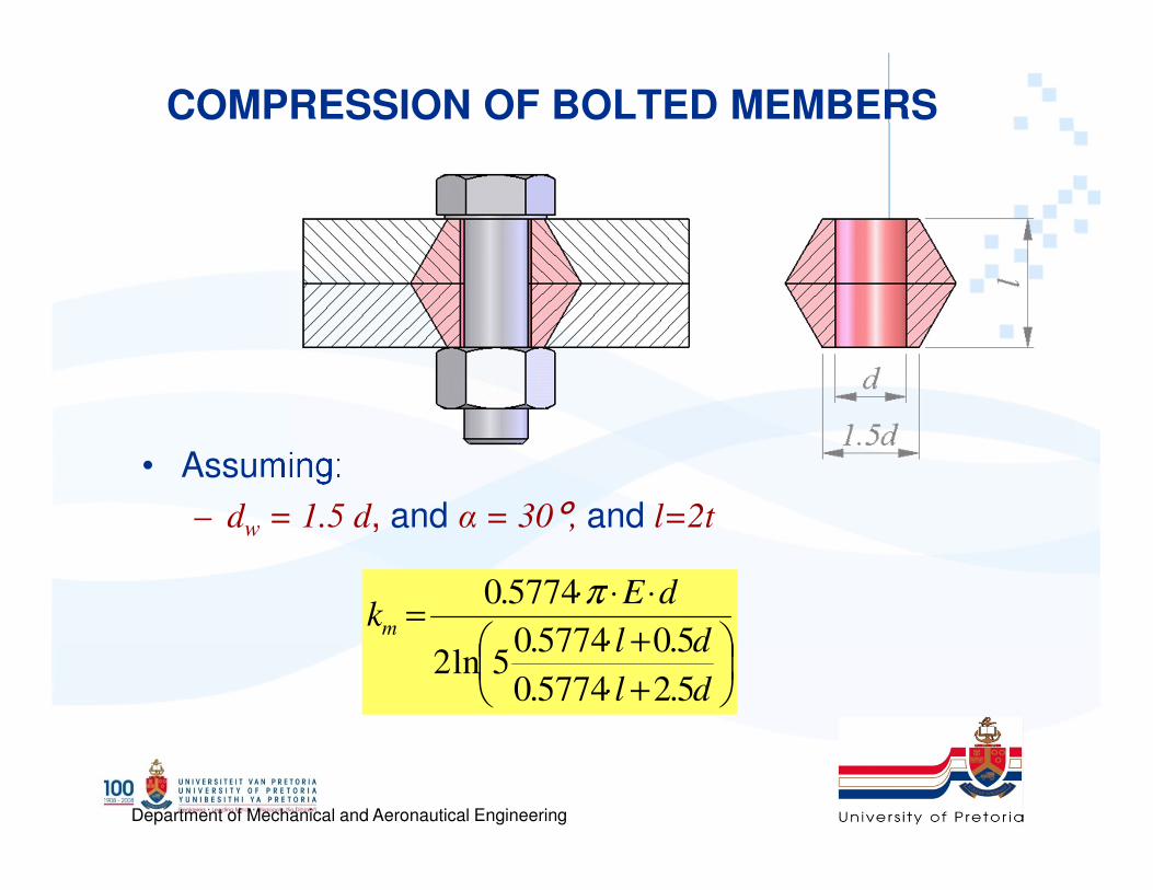
COMPRESSION OF BOLTED MEMBERS
• Assuming:
– dw = 1.5 d, and α = 30°, and l=2t
+⋅
+⋅
⋅⋅⋅=
dl
dl
dEkm
5.25774.0
5.05774.05ln2
5774.0 π

Department of Mechanical and Aeronautical Engineering
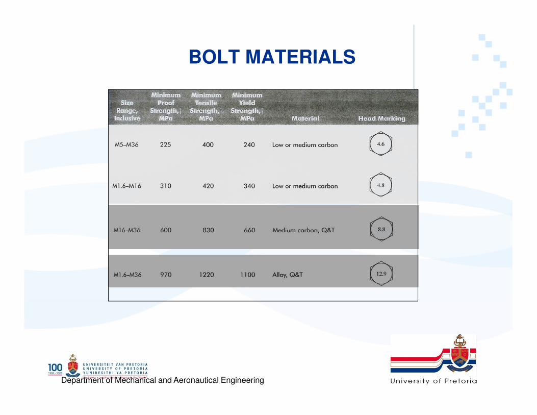
� Bolt strength is specified by:
1. minimum proof strength Sp
2. or minimum proof load Fp, 3. and minimum tensile strength, Sut
� The proof load is the maximum load (force)
that a bolt can withstand without acquiring a
permanent set.
� The proof strength is the quotient of the
proof load and the tensile-stress area.
Table 8-9 to 8-11
Bolt Strength
Department of Mechanical and Aeronautical Engineering
• Read section 8-6
*Use same grade nuts as the bolt

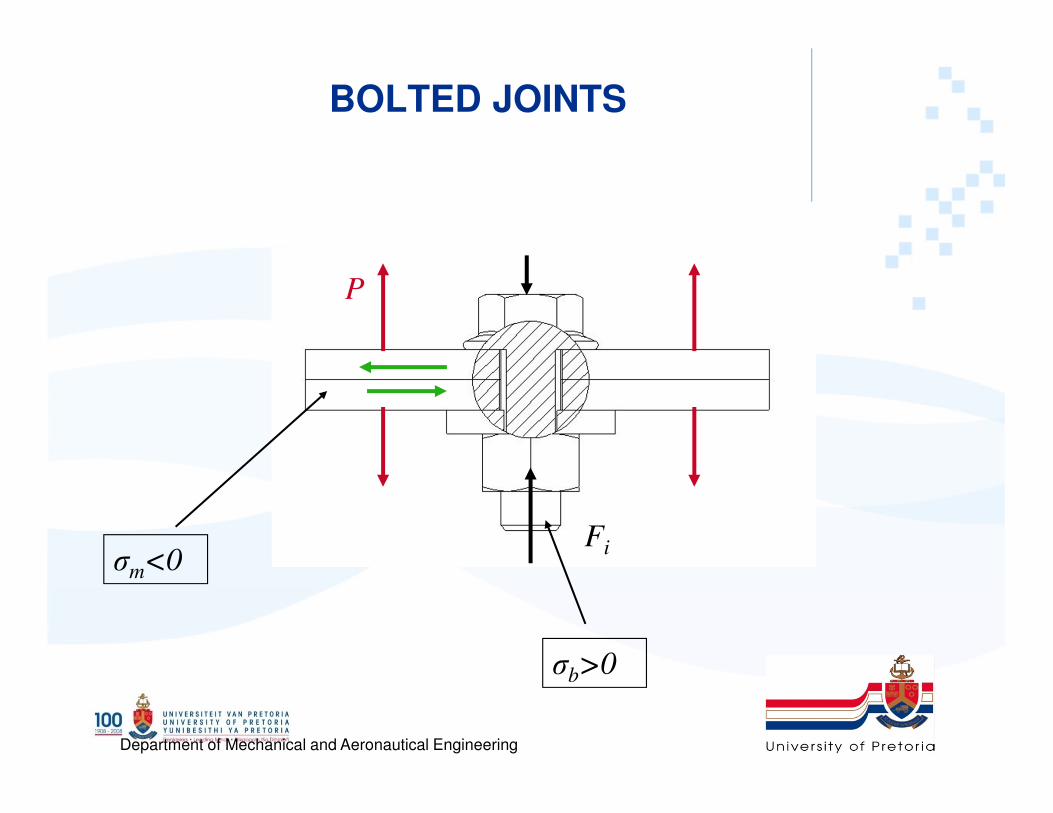
Department of Mechanical and Aeronautical EngineeringFi
P
BOLTED JOINTS IN TENSION
• Clearance between the bolt and hole
• Preload - Fi
• External tensile load – P
• External shear load – Ps
• Collar friction: fc
• Thread friction: ft
Department of Mechanical and Aeronautical Engineering
BOLTED JOINTS
Fi
P
σm<0
σb>0
Department of Mechanical and Aeronautical Engineering
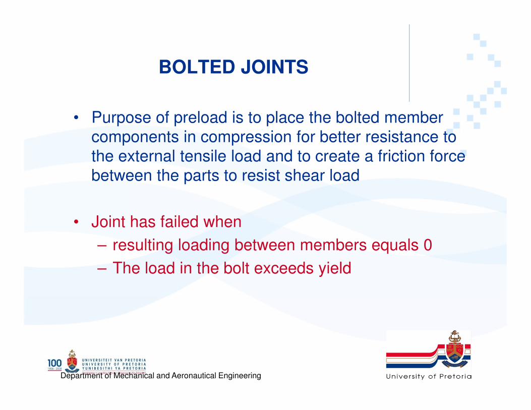
BOLTED JOINTS
• Purpose of preload is to place the bolted member
components in compression for better resistance to
the external tensile load and to create a friction force
between the parts to resist shear load
• Joint has failed when
– resulting loading between members equals 0
– The load in the bolt exceeds yield

Department of Mechanical and Aeronautical Engineering
BOLTED JOINTS
Spring constant or stiffness constant
– δ : Deflection
– F : Force
– A : Area
– E : Modulus of elasticity (Steel: E=200GPa)
Stiffness constant, k
L
EAFk
⋅==
δ
EA
LF
⋅
⋅=δ

Department of Mechanical and Aeronautical Engineering
BOLTED JOINTS
• P – total external load on bolted assembly
• Fi – Preload due to tightening
• Pb – Portion of P taken by bolt
• Pm – Portion of P taken by members
• Fb – Resultant bolt load = Pb + Fi
• Fm – Resultant load on members = Pm - Fi
• C – Fraction of P taken by bolt
mb PPP +=

Department of Mechanical and Aeronautical Engineering
BOLTED JOINTS
• Increase in deformation of the bolt
• Compression of members
b
b
k
P=∆δ
m
m
k
P=∆δ

Department of Mechanical and Aeronautical Engineering
BOLTED JOINTS
• On the assumption that the members have not separated, the
increase in deformation of the bolt must equal the decrease in
deformation of the members
– But
– rearranging
m
m
b
b
k
P
k
P==δ
mb PPP +=
PCPkk
kP
mb
bb ⋅=⋅
+=

Department of Mechanical and Aeronautical Engineering
BOLTED JOINTS
• The resultant load on the bolt is
• The resultant load on the member is
THESE EQUATIONS ARE ONLY VALID AS LONG AS SOME OF
THE INITIAL COMPRESSION REMAINS IN THE MEMBERS
iibb FPCFPF +⋅=+=
iimm FPCFPF −⋅−=−= )1(
mb
b
kk
kC
+=
Department of Mechanical and Aeronautical Engineering
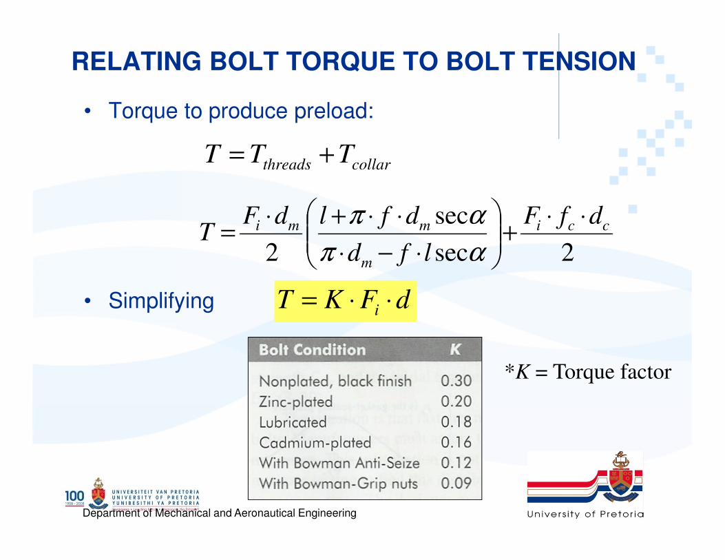
RELATING BOLT TORQUE TO BOLT TENSION
• Torque to produce preload:
• Simplifying
collarthreads TTT +=
2sec
sec
2
cci
m
mmi dfF
lfd
dfldFT
⋅⋅+
⋅−⋅
⋅⋅+⋅=
απ
απ
dFKT i ⋅⋅=
*K = Torque factor

Department of Mechanical and Aeronautical Engineering
• Tension, not torque, indicates proper joint tightness.
– Often, preload can be set more accurately by
controlling the number of turns rather than input
torque.
– Turn-of-nut method
• After the snug-tightening procedure is
completed, each bolt in the connection is pre-
tensioned additionally by the applicable amount
of relative rotation

Department of Mechanical and Aeronautical Engineering
STATICALLY LOADED TENSION JOINT
• Tensile stress failure
– Stress in bolt
– Introducing a load factor n:
• Where Sp is the proof stress
ib FPCF +⋅=
t
i
t
bA
F
A
PC+
⋅=σ
p
t
i
t
b SA
F
A
PnC=+
⋅⋅=σ

Department of Mechanical and Aeronautical Engineering
STATICALLY LOADED TENSION JOINT
• Joint separation
– The value of the load that will cause separation = P0
– At Joint Separation
• The Bolt Is Carrying All The Load
– Safety factor against separation, n0:
0PFb =
0)1( 0 =−⋅−= im FPCF
P
Pn 0
0 =
Portion of external
load carried by member
)1( CP
Fn i
o−−−−
====
Ratio of opening load
compared to external load

Department of Mechanical and Aeronautical Engineering
PRELOAD
• It is recommended that for static and fatigue
loading the following be used for preload
– Fi = 0.75 Fp (reused connections)
– Fi = 0.90 Fp (permanent connections)
– Where Fp is the proof load
ptp SAF ⋅=
Department of Mechanical and Aeronautical Engineering
BOLT MATERIALS
Department of Mechanical and Aeronautical Engineering
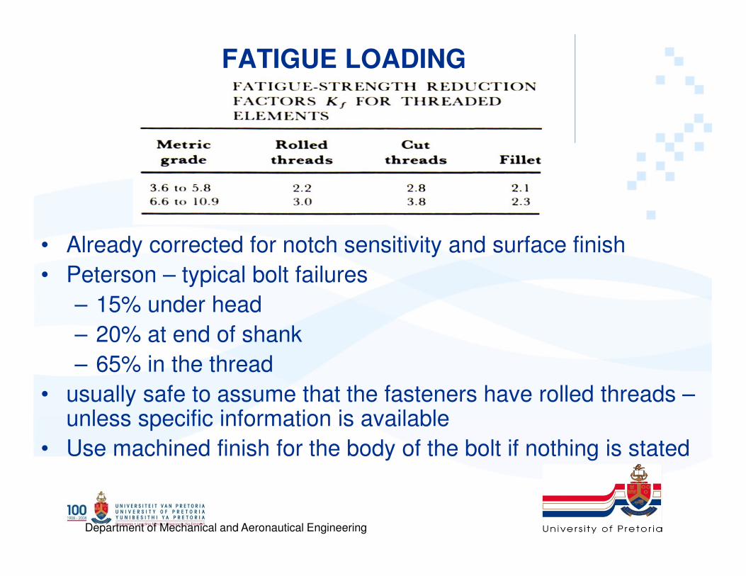
FATIGUE LOADING
• Already corrected for notch sensitivity and surface finish
• Peterson – typical bolt failures
– 15% under head
– 20% at end of shank
– 65% in the thread
• usually safe to assume that the fasteners have rolled threads –unless specific information is available
• Use machined finish for the body of the bolt if nothing is stated

Department of Mechanical and Aeronautical Engineering
Endurance Limit
• Fully corrected (including Kf) axial endurance
strength for rolled threads

Department of Mechanical and Aeronautical Engineering
FATIGUE LOADING• External load fluctuates between 0 and some
maximum force P
– Fmax = Fb
– Fmin = Fi
– Alternating component:
• Fa = (Fmax - Fmin)/2 = (Fb - Fi)/2
– Mean component:
• Fm = (Fmax+ Fmin)/2= (Fb + Fi)/2
– Alternating stress:
– Mean stress:
tt
ii
t
iba
A
PC
A
FFPC
A
FF
⋅
⋅=
⋅
−+⋅=
⋅
−=
22
)()
2(σ
t
i
tt
ii
t
ibm
A
F
A
PC
A
FFPC
A
FF+
⋅
⋅=
⋅
++⋅=
⋅
+=
22
)()
2(σ
iam σσσ +=
Load + pre-tension
Pre-tension
Department of Mechanical and Aeronautical Engineering
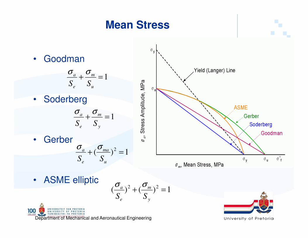
Mean Stress
• Goodman
• Soderberg
• Gerber
• ASME elliptic
1=+u
m
e
a
SS
σσ
1)( 2 =+u
ma
e
a
SS
σσ
1=+y
m
e
a
SS
σσ
1)()( 22 =+y
m
e
a
SS
σσ

Department of Mechanical and Aeronautical Engineering
FATIGUE LOADING
• Goodman
– But
(Applying the load factor to the alternating component only)
1=+u
m
e
a
SS
σσ
iam σσσ +=
1=+
+u
ia
e
a
SS
σσσ
1=+⋅
+⋅
u
iaf
e
af
S
n
S
n σσσ
)(
)(2
eu
ituef
SSPC
FASSn
+⋅
−⋅⋅=

Department of Mechanical and Aeronautical Engineering
160 kN
40 mm Table A-29 nut thickness 14.8 mm
20
20
M16 x 60 Grade 8.8
4 mm
40 + 14.8 + 4 =58.8 mm
..

Department of Mechanical and Aeronautical Engineering
60 mm
2 x 16 + 6 = 38 mm
60 – 38 = 22 mm
18 mm 157 mm2
0.0162 201 m m2
6102215718201
207157201
×+×
××
923.68 MN/m
100 GPa
⋅+⋅
⋅+⋅
⋅
165.2405774.0
165.0405774.05ln2
161005774.0 π
1609.08 MN/m
mMN
e
/19.1594
77871.016100 40/1661616.0
=
⋅⋅= ⋅

Department of Mechanical and Aeronautical Engineering
365.008.160968.923
68.923=
+
11, Sp=600MPa
(157)600 = 70.65kN
96.470650157600
1602365.0=
−⋅
⋅⋅
5
02.2)5160000(365.0
70650157600=
−⋅
5
0.9

Department of Mechanical and Aeronautical Engineering
Gasketed Joints
[[[[ ]]]]
63
)1(
)1(
≤≤≤≤≤≤≤≤
−−−−−−−−====
−−−−−−−−====
−−−−====
Nd
D
A
NCnPFp
FnPCF
NA
Fp
b
g
i
im
g
m
ππππ
Pressure p on gasket
Forces on members
Load Factor
Gasket pressure
To maintain adequate uniformity of pressure the bolts must
be spaced, not more than six diameters apart (rough rule)
Department of Mechanical and Aeronautical Engineering
Summary: BOLT SIZING
• Factors used during bolt sizing
– Bolt size
– Number of bolts
– Bolt material
– Type of loading
– Bolt preload
– Safety factor
– Load/pressure at failure
– Member material
• Note:
– Any of the above can be used as an entry point for
the sizing of a bolted connections