Moving Canning Bus Bridge Sideways - wyche …wyche.com.au/wp-content/uploads/2007/05/Shifting the...
11
Shifting the Canning Bus Bridge Sideways - MacKinlay Page 1 of 11 Shifting the Canning Bus Bridge Sideways Ros MacKinlay – Design Engineer, Wyche Consulting SYNOPSIS The Perth – Mandurah railway proposed in 2002 required the replacement of an existing Kwinana Freeway bus bridge. As a cost saving alternative the successful tenderer proposed that the existing bridge superstructure be moved rather than rebuilt. In 2005 this curved prestressed concrete bridge superstructure was successfully moved a distance of 9.5 metres South West of its original location to remain in use carrying buses from Canning Highway onto the north bound Kwinana Freeway. This paper provides an example of the economy which is achievable by modifying and re-using an existing structure, but also shows that the bridge engineering challenges for keeping old structures are often more difficult than designing new ones. 1 INTRODUCTION The Main Roads WA called tenders in 2003 for the design and construction of the railway, the major bridges and associated road works for the South West Metropolitan Railway Project. The Package E component for this Perth to Mandurah Railway Project included the demolition of the existing Canning Highway bus bridge (MRWA bridge number 1295), and the construction of a new bridge approximately 9.5 metres to the South West. Leighton Contractors, with the assistance of the temporary works consultant, Hawkins Engineering, and their engineering consultants, demonstrated a significant capital cost saving with the relocation of the existing bridge superstructure in its entirety to the new location, in lieu of the construction of a new bridge. This relocation option was included in the final Package E contract with the MRWA. The relocation of the bridge superstructure required:- • Detailed analysis of the existing structure for support options, loads and tolerance bands for the shift. • New design of the complicated West abutment. • Development of a unique temporary works system and staging sequences. • Careful monitoring of the loads and settlements during the move. All with minimum disruption to the Freeway traffic.
Transcript of Moving Canning Bus Bridge Sideways - wyche …wyche.com.au/wp-content/uploads/2007/05/Shifting the...

Shifting the Canning Bus Bridge Sideways - MacKinlay Page 1 of 11
Shifting the Canning Bus Bridge Sideways
Ros MacKinlay – Design Engineer, Wyche Consulting
SYNOPSIS The Perth – Mandurah railway proposed in 2002 required the replacement of an existing Kwinana Freeway bus bridge. As a cost saving alternative the successful tenderer proposed that the existing bridge superstructure be moved rather than rebuilt. In 2005 this curved prestressed concrete bridge superstructure was successfully moved a distance of 9.5 metres South West of its original location to remain in use carrying buses from Canning Highway onto the north bound Kwinana Freeway. This paper provides an example of the economy which is achievable by modifying and re-using an existing structure, but also shows that the bridge engineering challenges for keeping old structures are often more difficult than designing new ones.
1 INTRODUCTION The Main Roads WA called tenders in 2003 for the design and construction of the railway, the major bridges and associated road works for the South West Metropolitan Railway Project. The Package E component for this Perth to Mandurah Railway Project included the demolition of the existing Canning Highway bus bridge (MRWA bridge number 1295), and the construction of a new bridge approximately 9.5 metres to the South West. Leighton Contractors, with the assistance of the temporary works consultant, Hawkins Engineering, and their engineering consultants, demonstrated a significant capital cost saving with the relocation of the existing bridge superstructure in its entirety to the new location, in lieu of the construction of a new bridge. This relocation option was included in the final Package E contract with the MRWA. The relocation of the bridge superstructure required:-
• Detailed analysis of the existing structure for support options, loads and tolerance bands for the shift.
• New design of the complicated West abutment. • Development of a unique temporary works system and staging sequences. • Careful monitoring of the loads and settlements during the move.
All with minimum disruption to the Freeway traffic.

Shifting the Canning Bus Bridge Sideways - MacKinlay Page 2 of 11
2 EXISTING BRIDGE The Bridge No.1295 at the Kwinana Freeway / Canning Highway Interchange was designed in 1988 and constructed during 1988/1989. It is used to carry buses from Canning Highway over the Kwinana Freeway Northbound lanes and onto the centre bus lane on the Kwinana freeway bound for Perth. The existing bridge superstructure is a voided prestressed concrete beam section, curved both vertically and in plan, and is approximately 126 metres long (supported length 124 metres) along the centre line of the bridge. It has a 60 metre long curved section (with a tight 77.5 metre horizontal radius) which was originally incrementally launched from the West abutment area, and joined to the straight cast insitu section ending at the North abutment. It is supported at four locations. Refer to Figure 1 for extracts from the original drawings.
Figure 1: Original Canning Bus Bridge # 1295 Drawing Extracts
The bridge details are: Deck: One lane for vehicles up to T44 loading. Straight section deck width 5.5m
(4m lane) and curved deck width 6.1m (4.6m lane) Spans: North Abutment to Pier 1 : 30 metres (straight)
Pier 1 to Pier 2 : 40 metres (curved near Pier 1) Pier 2 to West Abutment : 54 metres (curved in plan 77.5m radius)
Weight: Permanent superstructure components 1560 T. It is apparent from the physical appearance and survey data of the existing superstructure that the bridge has distorted from its original intended shape. The longest span of 54m (being the curved section over the Freeway) appears to have twisted outwards so that the deck has a reduced cross fall and the soffit slopes slightly in the opposite direction to the intended slope on the original design drawings.

Shifting the Canning Bus Bridge Sideways - MacKinlay Page 3 of 11
Whatever the reality about deflections, our calculations showed that torsion, shear and bending appear to be correctly designed for in the superstructure. It was not a contract requirement to re-establish the original intended shape of the superstructure, and the repositioning was managed so that bridge, in its new position, is almost exactly the same shape as previously. 3 CLIENT REQUIREMENTS The existing superstructure was to be moved approximately 9.5 metres in a south west direction in its ‘as existing’ condition and relocated onto new substructure components which consist of abutments, exit ramp and two intermediate piers. The bridge in its new location was required to provide the same function as originally existed - that being for bus access to the centre lanes of the Kwinana Freeway from Canning Highway. Contract requirements for this bridge were:-
• Only the existing bridge superstructure and modified Western Abutment (approach retaining walls) could be re-used.
• New intermediate piers to be single columns designed to resist train impact loads of 3000kN longitudinal and 1500kN transverse.
• The Northern Abutment barriers to be AS5100 Medium Performance - 500kN transverse outward. (Previous design impact load 90kN)
• Vertical clearance over Freeway in new position to be minimum 5.02 m. (Previous design clearance 4.95m)
• Traffic loading design for T44 (same as existing bridge) 4 DESIGN 4.1 Superstructure Model The superstructure was modelled as a two dimensional grillage as per Figure 2.
RADIU
S 77.5
m
PIER
1
TEM
PORA
RY
SUPP
ORT
2
N0RT
H AB
UTM
ENT
TEM
PORA
RY
SUPP
ORT
1
TEM
PORA
RY
SUPP
ORT
3
TEM
PORA
RY
SUP
PORT
4PIER
2
WEST ABUTMENT
BEAM CROSS SECTION
TRANSVERSE STIFF
MEMBERS
LONGITUDINAL EDGE MEMBERS DEFINE VEHICLE BOUNDARY
NODE SPACING 1m (TYP)
4.0m
4.6m
2.1m
2.4m
LAN
E
LANE0.75m
LANE
10mMODEL SCALE
MAIN LONGITUDINAL BEAM PROPERTIESIx = 2.4 m^4Iy = 7.0 m^4J = 3.4 m^4
Figure 2: Model Data Bridge #1295

Shifting the Canning Bus Bridge Sideways - MacKinlay Page 4 of 11
4.2 Superstructure Results The model provided results which showed significant shear and torsion values around the curved part of the bridge and that the superstructure was very sensitive to applied differences in elevation at the supports (as might be expected during relocation). The critical section of the existing bridge superstructure was west of Pier 2, as this was the longest span and also curved in plan. The “in service” calculated shear and torsion values in this section were significant even under permanent effects only. The required location for the adjacent Temporary support (TS3) was where the prestress cable slope added shear to the construction shear forces and the installed shear reinforcement was less than at the permanent support location. The calculated combined bending, shear and torsion capacity of the existing superstructure at TS3 in this area could only tolerate very small applied vertical differences and still remain within ultimate allowable code values. An additional temporary support between Pier 2 and the West abutment would have provided significantly lower shear forces on the superstructure, but this was not possible as it would have interfered with the Freeway traffic and added significantly to the project costs. After exhaustive calculations, the vertical and horizontal movement tolerance bands and maximum loads at each temporary support were established for the 3 stages of the relocation. Some of the Stage 1 vertical lift tolerances and loads are shown in Figure 3.
NEW WEST ABUTMENT
NEW PIER 2
NEW NORTH
ABUTMENT
NEW PIER 1
EXISTING PIER 1
EXISTING PIER 2
EXISTING WEST ABUTMENT
EXISTINGNORTH
ABUTMENT
TEMPORARY SUPPORT TS2
TEMPORARY SUPPORT TS3
TEMPORARY SUPPORT TS1
TEMPORARY SUPPORT TS4
ORIGINAL POSITION
RELOCATED POSITION
TS1 TS2 TS3 TS4
-30 MM -30 MM
+30 MM+10 MM
TS1 NOT MORE THAN 30 MM ABOVE OR BELOW TS2TS3 NOT MORE THAN 10 MM ABOVE OR 30 MM BELOW LINE JOINING TS2 AND TS4
LINE OF ORIGINAL RELATIVE LEVELS
ALLOWABLE LEVEL TOLERANCE BAND FOR LIFT/ LOWER
10mSCALE
EAST BEARING VERTICAL LOADS FROM
PERMANENT & THERMAL EFFECTS:-
SERVICEABILITY : 3152 kNULTIMATE : 3818 kN
WEST BEARING VERTICAL LOADS FROM
PERMANENT & THERMAL EFFECTS:-
SERVICEABILITY : 2879 kNULTIMATE : 3741 kN
JACKING POINTS / SUPPORTS AT TS3(POSITIONED ALONG LINE OF MOVEMENT)TS1,TS2 & TS4 WERE SIMILARLY DEFINED
Figure 3: Loads and Tolerances for Vertical Lift of Superstructure
Tolerance bands were also established for the Stage 2 horizontal move, as the superstructure was moved by pulling from two TS locations only, potentially causing torsion stresses related to horizontal distortions. Detailed sequencing guidelines and

Shifting the Canning Bus Bridge Sideways - MacKinlay Page 5 of 11
tolerance ranges were also established for the Stage 3 lowering of the bridge onto the new substructures with the aim of minimising additional superstructure stresses that may be caused by differential settlement of the new foundations. 4.3 West Abutment There are significant permanent torsion forces in the superstructure caused by the horizontal curve around the longest span. This causes uplift forces on the inside (NW) corner of the superstructure at the West Abutment. In the original design the superstructure was tied down at this location to the West Abutment with 4 stress bars - each stressed to 500kN. The west abutment footing was also further fixed to the subsoil with ground anchors to prevent uplift. The new west abutment design provides for the bridge to be stressed down to the West abutment at the same superstructure location, but the shape and design of the new abutment put the resultant of the superstructure loads at the centre of a new spread footing, offset from the centreline of the superstructure. In this way the twisting effect of the superstructure on the abutment is transferred to the subsoil as fairly even safe working pressures, and there is therefore no requirement for the ground anchors. The offset footing also fits neatly into the available space within the existing retaining walls as shown in Figure 4.
RL 4.880
RL 3.480
RL 1.250
EXISTING SIDERETAINING WALL BEHIND
RL 4.300RL 4.800
CL N
EW
ABUT
MEN
T
SECTION ON BRIDGE FINAL CENTRE LINE ELEVATION LOOKING WESTERLY DIRECTION(EARTHWORKS EXCLUDED)
RL 6.655
RL 4.800
EXISTING ABUTMENT
NEW ABUTMENT BASE
STRESS BAR TIE DOWN
EXISTING ABUTMENT
RELOCATED SUPERSTRUCTURE
NEW ABUTMENT BASE
FREE
WAY
SHEETPILE
EXISTING FOOTING
NEW FRONT WALL
NEW FRONT WALL
EXISTING
FOOTING
TOP RL 4.300
CL E
XIST
ING
ABUT
MENT
EXISTING FOOTING
TOP RL 3.480
EXISTING FOOTING
TOP RL 4.880
BR 1057 EXISTING FOOTING
TOP RL 1.250
EXISTING FOOTINGTOP RL 5.400
EXIS
TING
FO
OTIN
GTO
P RL
1.25
0
1400
THI
CK
BRIDGE FINAL CL
CL N
EW
ABUT
MENT
NEW
ISOL
ATED
FOO
TING
TOP
RL 1.
250
1000
THI
CK
APPROACH RETAINING WALL
(EXISTING)
TEMPORARY BLADE WALL
RELOCATED SUPERSTRUCTURE
PLAN(VIEW THROUGH ROAD)
STRESS BAR TIE DOWN
NOTE: NEW WEST ABUTMENT STRUCTURE IS TOTALLY ISOLATED FROM EXISTING STRUCTURES
INTERNAL RETAINING WALL
APPROACH SLAB
INTE
RNAL
RET
WAL
L
BRIDGE 1057 CANNING
HIGHWAY EAST BOUND
EXIS
TIN
G
BR 1
057
CANN
ING
HW
YEA
ST B
OU
ND
2m
SCALE
Figure 4: Bridge #1295 West Abutment

Shifting the Canning Bus Bridge Sideways - MacKinlay Page 6 of 11
4.4 North Abutment The North Abutment design was similar to the existing abutment except that the exit ramp vehicle impact barriers were required to be designed for medium performance (500kN) loads. This requirement meant that full height concrete barriers were required at the top of the exit ramp instead of the existing three rail barriers, due to the proximity to the rail corridor to this new structure. 4.5 Piers The new piers and footings were required to be designed to resist train impact loads of 3000kN along the rail line and 1500kN perpendicular to the rail. This was facilitated by integrating the existing pier foundations with the new footing and making the footing shape such that the temporary works blade wall was located on the permanent footing. This design ensured that the soil bearing pressures remained within acceptable limits under all load conditions and that there was minimal differential settlement between the old support, the temporary support and the new pier by the time the final bearing changeover was made. See Figure 5.
NEW PIER 2AND FOUNDATIONS
FOUNDATIONS FOREXISTING PIER 2 4000
750
4000
3300
2500
14300 MIN
OUTLINE OF
RELOCATED BRIDGE
OUTLINE OF
ORIGINAL BRIDGE
BLADE WALL FOR TS3
PLAN PIER 2 AND TS3
CENTRE LINE OF
RAIL UP MAIN
SOFFIT SUPPORT AREA
CL PIER 2
TOP OF NEW PIER RL 7.149
ELEVATION PIER 2 & TS3
CL TS3
APPROX GROUND LEVEL
BLADE WALL (TEMPORARY WORKS) TO BE REMOVED AT BASE OF WALL AFTER BRIDGE MOVE
NEW FOOTINGDOWELED TO EXISTING
700 to 800 CLEARFOR SUPPORT CRADLE
750 TOP OF NEW FOOTING RL 1.543
RAIL UP MAIN
1700
Figure 5: Bridge #1295 Pier 2 Footing

Shifting the Canning Bus Bridge Sideways - MacKinlay Page 7 of 11
5 CONSTRUCTION 5.1 Temporary Works There was close liaison between the contractors, the temporary works specialist and the designers (see 7. Acknowledgment) to establish the locations, sizes, structural aspects, loadings and construction tolerances for the temporary supports. The temporary works contractor designed or arranged the temporary works concepts, the steel cradles and bearings to support the bridge and the horizontal and vertical jacking systems required for the move. The temporary works consisted of concrete blade walls near each permanent support. The blade wall foundations were made integral with the foundations for the new and old permanent structures at Pier 1, Pier 2 (see Figure 5) and at the West abutment the temporary blade wall was integrated with the existing abutment foundations. In this way differential settlement between the old foundations, temporary works and new foundations was minimised. Only the lightly loaded TS1 at the North Abutment was totally separate from the permanent works. A steel cradle was bolted to the sides of the superstructure and grouted to the soffit at each of the temporary support points. Each cradle was supported on bearings located directly under the superstructure webs, and shims above the bearing were used to set the height after jacking. Vertical jacking was achieved by temporary jacks under the cradle either side of the slide bearings. See Figure 6.
Figure 6: Bridge #1295 Temporary Works Diagram
(Reproduced from Hawkins Engineering Drawings)

Shifting the Canning Bus Bridge Sideways - MacKinlay Page 8 of 11
The horizontal movement was achieved by a hydraulic jacking system attached to a frame on the west end of the blade walls for TS2 and TS4 (with option to attach to TS1 and TS3 if required). The horizontal jack was attached to the bridge cradle via a 40mm diameter stress bar. In addition TS1 and TS4 had side guide rollers attached to the cradle to ensure horizontal movement only along the line of the blade wall. During the horizontal movement of the bridge, each cradle was moved along its blade wall on a series of launch pads placed under each bearing – the same as those used in incremental launching systems.
Figure 7: Support Cradle and Horizontal Jacking System at TS2
5.2 Staging of Construction and Relocation The staging of the demolition, construction and moving of the superstructure required careful planning to ensure minimisation of construction stresses on the superstructure and to allow continuity of the Freeway traffic. The basic sequence of the works was:- 5.2.1 Demolition and Construction Special care was required during this phase to ensure that the existing bridge deck, prestress tie-down at the West Abutment and existing bearing arrangements were not disturbed.
• Redirect bus traffic, reduce lane widths on northbound Kwinana Freeway and re-align. Install temporary impact barriers near works on side of Freeway.
• Construct North Abutment (leaving off the East upstand to allow the superstructure to pass across during the move) and construct blade wall TS1 and foundations.
• Construct new columns and footings for Piers 1 and 2, dowel to existing pier footings, and construct blade walls TS2 and TS3.
• Demolish approach slab and underlying earthworks to West Abutment and the side wall of existing abutment back to the location of new abutment base. This excavation exposed the retaining wall footings of the older Canning Bridge #1057, and the bridge #1295 retaining wall. Some of these footings were higher than the level of new abutment and needed to be protected with sheet pile walls during construction.
Shifting the Canning Bus Bridge Sideways - MacKinlay Page 9 of 11
• Construct blade wall TS4 at the West Abutment (this was a detailed sequencing of works utilising part of the existing abutment which was still supporting the bridge).
• Construct the base slab only for the new West Abutment. This abutment is not joined to any part of the existing remaining permanent bridge structures and accordingly allows the relocated structure and new foundations to settle separately to the existing permanent works.
• Install temporary cradles and jacking equipment at TS1, TS2, TS3 and TS4. 5.2.2 Moving the Superstructure The superstructure was moved in three distinct stages, requiring careful monitoring of different ranges of tolerances, levels and loads for each stage. The role of the surveyor was critical to the successful monitoring of the vertical and horizontal tolerance bands during the moving of this bridge. Stage 1 - Vertical lift to jack the superstructure free of the existing bearings, jack to
final height, shim and support it entirely on the temporary support cradles. • Jack in stages at TS1, TS2 and TS3 (staying within tolerance band). • Remove tie down stress bars at the West Abutment . • Jack TS4 and TS3 in stages.
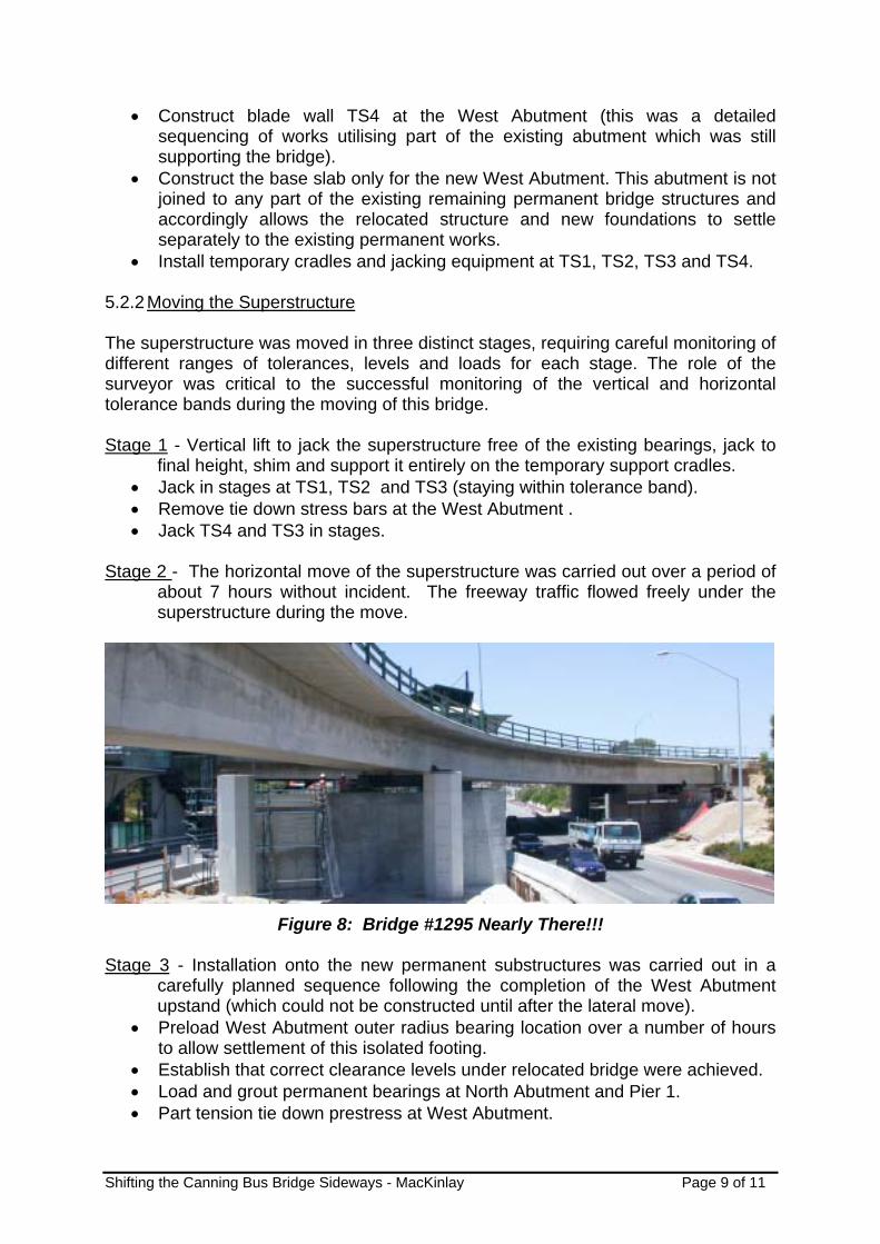
Stage 2 - The horizontal move of the superstructure was carried out over a period of
about 7 hours without incident. The freeway traffic flowed freely under the superstructure during the move.
Figure 8: Bridge #1295 Nearly There!!!
Stage 3 - Installation onto the new permanent substructures was carried out in a
carefully planned sequence following the completion of the West Abutment upstand (which could not be constructed until after the lateral move).
• Preload West Abutment outer radius bearing location over a number of hours to allow settlement of this isolated footing.
• Establish that correct clearance levels under relocated bridge were achieved. • Load and grout permanent bearings at North Abutment and Pier 1. • Part tension tie down prestress at West Abutment.

Shifting the Canning Bus Bridge Sideways - MacKinlay Page 10 of 11
• Install West Abutment bearing and complete tie down prestress. • Install Pier 2 permanent bearings.
5.2.3 Complete Construction
• Remove all above ground temporary works and demolish TS1 and other three blade walls down to footing level.
• Complete the remaining permanent works, including West Abutment retaining wall and approach works, the North Abutment exit ramp, the deck refurbishment works as required and installation of road infrastructure.
• Demolition of old works at North Abutment, ramp and Piers 1 & 2 to ground level and required backfilling.
• Remove temporary road barriers and reinstate freeway lanes. 5.3 Problems Encountered Some of the problems associated with re-use of this existing structure included: 1. The distorted shape of the superstructure made it very difficult to fit a road
design to the bridge and the approaches. 2. The uneven sag of the existing structure also caused difficulties in establishing
existing clearances and predicting relocated position clearances. This was only achieved with many spot heights and extrapolation of the results.
3. Code changes since the original design resulting in theoretically low strength reserves in the structure as well as very tight tolerance bands for the move.
4. Problems in freeing existing West abutment outer bearing, potentially causing undue stress on the superstructure. The abutment below the bearing had to be broken away from the superstructure to free it up.
5. The brake-out friction between the temporary bearings and sliding pads was larger than anticipated, delaying the start of the move. This was overcome by jacking the bridge at each bearing and greasing the pads.
6 CONCLUSIONS The successful relocation of this existing traffic bridge required close liaison between the designers, the temporary works consultant and the construction team, and presented some quite different design and construction challenges compared to the construction of a new bridge. There was much more design emphasis on construction tolerances and more designer involvement during the construction and relocation phase than would be expected for a new bridge of this type. The bridge relocation was achieved well within the time constraints for the overall project as the use of the existing superstructure saved considerable construction time and also minimised disruption to the Freeway traffic. This relocation of an existing superstructure also contributed a significant and worthwhile saving to the South West Metro Rail Project compared to the cost of a new structure and the bridge is now in-service for bus traffic southbound to the city.

Shifting the Canning Bus Bridge Sideways - MacKinlay Page 11 of 11
7 ACKNOWLEDGMENT The Author and Wyche Consulting wish to acknowledge the team that contributed to the successful implementation of this project. They are Leighton Contractors, the temporary works consultant Hawkins Engineering, the geotechnical consultant Coffey, GHD for additional design and the drafting input, as well as the client Main Roads WA.