Moving and rotating faces - Support
124
Moving and rotating faces Publication Number spse01520
Transcript of Moving and rotating faces - Support

Moving and rotating faces
Publication Numberspse01520


Moving and rotating faces
Publication Numberspse01520

Proprietary and restricted rights notice
This software and related documentation are proprietary to Siemens ProductLifecycle Management Software Inc.
© 2010 Siemens Product Lifecycle Management Software Inc. All Rights Reserved.
All trademarks belong to their respective holders.
2 Moving and rotating faces spse01520

Contents
Introduction . . . . . . . . . . . . . . . . . . . . . . . . . . . . . . . . . . . . . . . . . . . . . . 1-1
Part modification by moving and rotating faces and planes . . . . . . . . . 2-1
Moving synchronous faces . . . . . . . . . . . . . . . . . . . . . . . . . . . . . . . . . . . 3-1
Graphic handle (3D steering wheel) . . . . . . . . . . . . . . . . . . . . . . . . . . . . . . . 3-2Moving a face . . . . . . . . . . . . . . . . . . . . . . . . . . . . . . . . . . . . . . . . . . . . . . . 3-6Rotating a face . . . . . . . . . . . . . . . . . . . . . . . . . . . . . . . . . . . . . . . . . . . . . . 3-6Move face workflow . . . . . . . . . . . . . . . . . . . . . . . . . . . . . . . . . . . . . . . . . . . 3-6Activity: Move and rotate faces . . . . . . . . . . . . . . . . . . . . . . . . . . . . . . . . . . 3-7Activity: Copying a face and using keypoints to define movement . . . . . . . . . . 3-8
Selecting faces . . . . . . . . . . . . . . . . . . . . . . . . . . . . . . . . . . . . . . . . . . . . . 4-1
Selection mode . . . . . . . . . . . . . . . . . . . . . . . . . . . . . . . . . . . . . . . . . . . . . . 4-1Selection manager . . . . . . . . . . . . . . . . . . . . . . . . . . . . . . . . . . . . . . . . . . . 4-2
QuickBar options for moving faces . . . . . . . . . . . . . . . . . . . . . . . . . . . . . 5-1
Connected face options . . . . . . . . . . . . . . . . . . . . . . . . . . . . . . . . . . . . . . . . 5-1Copy . . . . . . . . . . . . . . . . . . . . . . . . . . . . . . . . . . . . . . . . . . . . . . . . . . . . . 5-2Detach . . . . . . . . . . . . . . . . . . . . . . . . . . . . . . . . . . . . . . . . . . . . . . . . . . . . 5-3Precedence . . . . . . . . . . . . . . . . . . . . . . . . . . . . . . . . . . . . . . . . . . . . . . . . . 5-4
Working with Live Sections . . . . . . . . . . . . . . . . . . . . . . . . . . . . . . . . . . 6-1
Activity: Live Section . . . . . . . . . . . . . . . . . . . . . . . . . . . . . . . . . . . . . . . . . 6-3
Activity: Moving and rotating faces . . . . . . . . . . . . . . . . . . . . . . . . . . . . A-1
Move a face . . . . . . . . . . . . . . . . . . . . . . . . . . . . . . . . . . . . . . . . . . . . . . . . A-1Move faces . . . . . . . . . . . . . . . . . . . . . . . . . . . . . . . . . . . . . . . . . . . . . . . . . A-3Rotate a face . . . . . . . . . . . . . . . . . . . . . . . . . . . . . . . . . . . . . . . . . . . . . . . A-3Summary . . . . . . . . . . . . . . . . . . . . . . . . . . . . . . . . . . . . . . . . . . . . . . . . . . A-4
Activity: Copying a face and using keypoints to define movement . . . . B-1
Select the hole to copy . . . . . . . . . . . . . . . . . . . . . . . . . . . . . . . . . . . . . . . . . B-1Define the move from point . . . . . . . . . . . . . . . . . . . . . . . . . . . . . . . . . . . . . B-2Define the move direction . . . . . . . . . . . . . . . . . . . . . . . . . . . . . . . . . . . . . . B-3Define the move distance . . . . . . . . . . . . . . . . . . . . . . . . . . . . . . . . . . . . . . . B-4Verify move distance . . . . . . . . . . . . . . . . . . . . . . . . . . . . . . . . . . . . . . . . . . B-6Summary . . . . . . . . . . . . . . . . . . . . . . . . . . . . . . . . . . . . . . . . . . . . . . . . . . B-7
Activity: Using the Selection Manager . . . . . . . . . . . . . . . . . . . . . . . . . . C-1
Select all rounds of equal radius . . . . . . . . . . . . . . . . . . . . . . . . . . . . . . . . . . C-1Change the round radius . . . . . . . . . . . . . . . . . . . . . . . . . . . . . . . . . . . . . . . C-2
spse01520 Moving and rotating faces 3
Contents
Use the selection box . . . . . . . . . . . . . . . . . . . . . . . . . . . . . . . . . . . . . . . . . . C-3Define selection box area . . . . . . . . . . . . . . . . . . . . . . . . . . . . . . . . . . . . . . . C-4Define select box depth . . . . . . . . . . . . . . . . . . . . . . . . . . . . . . . . . . . . . . . . C-5Change radius of select set . . . . . . . . . . . . . . . . . . . . . . . . . . . . . . . . . . . . . C-5Summary . . . . . . . . . . . . . . . . . . . . . . . . . . . . . . . . . . . . . . . . . . . . . . . . . . C-6
Activity: Modifying a part by moving select sets . . . . . . . . . . . . . . . . . . D-1
Suspend Live Rules . . . . . . . . . . . . . . . . . . . . . . . . . . . . . . . . . . . . . . . . . . D-1Select feature to move . . . . . . . . . . . . . . . . . . . . . . . . . . . . . . . . . . . . . . . . . D-1Move the feature . . . . . . . . . . . . . . . . . . . . . . . . . . . . . . . . . . . . . . . . . . . . D-3Select the channel-shaped feature . . . . . . . . . . . . . . . . . . . . . . . . . . . . . . . . D-4Move the channel-shaped feature . . . . . . . . . . . . . . . . . . . . . . . . . . . . . . . . . D-5Extend the legs of the channel-shaped feature . . . . . . . . . . . . . . . . . . . . . . . . D-5Move top face of channel-shaped feature . . . . . . . . . . . . . . . . . . . . . . . . . . . . D-6Move protrusion feature to end of part . . . . . . . . . . . . . . . . . . . . . . . . . . . . . D-7Summary . . . . . . . . . . . . . . . . . . . . . . . . . . . . . . . . . . . . . . . . . . . . . . . . . . D-8
Activity: Copying and attaching a feature (method 1) . . . . . . . . . . . . . . E-1
Select the feature to copy . . . . . . . . . . . . . . . . . . . . . . . . . . . . . . . . . . . . . . . E-1Suspend Live Rules . . . . . . . . . . . . . . . . . . . . . . . . . . . . . . . . . . . . . . . . . . E-2Set the copy option and move the feature . . . . . . . . . . . . . . . . . . . . . . . . . . . E-2Define the move distance and direction . . . . . . . . . . . . . . . . . . . . . . . . . . . . . E-3Change move direction . . . . . . . . . . . . . . . . . . . . . . . . . . . . . . . . . . . . . . . . E-4Move by keying in a distance . . . . . . . . . . . . . . . . . . . . . . . . . . . . . . . . . . . . E-5Attach the copied feature . . . . . . . . . . . . . . . . . . . . . . . . . . . . . . . . . . . . . . . E-7Summary . . . . . . . . . . . . . . . . . . . . . . . . . . . . . . . . . . . . . . . . . . . . . . . . . . E-7
Activity: Copying and attaching a feature (method 2) . . . . . . . . . . . . . . F-1
Suspend Live Rules . . . . . . . . . . . . . . . . . . . . . . . . . . . . . . . . . . . . . . . . . . F-1Select the feature to copy . . . . . . . . . . . . . . . . . . . . . . . . . . . . . . . . . . . . . . . F-1Set the copy option and move the feature . . . . . . . . . . . . . . . . . . . . . . . . . . . F-2Relocate the steering wheel origin . . . . . . . . . . . . . . . . . . . . . . . . . . . . . . . . F-3Move the copied feature using the steering wheel plane . . . . . . . . . . . . . . . . . F-3Summary . . . . . . . . . . . . . . . . . . . . . . . . . . . . . . . . . . . . . . . . . . . . . . . . . . F-4
Activity: Detaching and attaching a feature . . . . . . . . . . . . . . . . . . . . . G-1
Suspend Live Rules . . . . . . . . . . . . . . . . . . . . . . . . . . . . . . . . . . . . . . . . . . G-1Select the feature to detach . . . . . . . . . . . . . . . . . . . . . . . . . . . . . . . . . . . . . G-2Position the steering wheel origin . . . . . . . . . . . . . . . . . . . . . . . . . . . . . . . . . G-2Move the feature . . . . . . . . . . . . . . . . . . . . . . . . . . . . . . . . . . . . . . . . . . . . G-2Attach the feature . . . . . . . . . . . . . . . . . . . . . . . . . . . . . . . . . . . . . . . . . . . G-4Summary . . . . . . . . . . . . . . . . . . . . . . . . . . . . . . . . . . . . . . . . . . . . . . . . . . G-4
Activity: Copying, rotating, and attaching a feature to a newlocation . . . . . . . . . . . . . . . . . . . . . . . . . . . . . . . . . . . . . . . . . . . . . . . . . . H-1
Suspend Live Rules . . . . . . . . . . . . . . . . . . . . . . . . . . . . . . . . . . . . . . . . . . H-1Method one overview . . . . . . . . . . . . . . . . . . . . . . . . . . . . . . . . . . . . . . . . . H-2Select the feature . . . . . . . . . . . . . . . . . . . . . . . . . . . . . . . . . . . . . . . . . . . . H-2Move the copied feature . . . . . . . . . . . . . . . . . . . . . . . . . . . . . . . . . . . . . . . . H-3Align the feature to the angled face . . . . . . . . . . . . . . . . . . . . . . . . . . . . . . . H-4Position the feature . . . . . . . . . . . . . . . . . . . . . . . . . . . . . . . . . . . . . . . . . . . H-5
4 Moving and rotating faces spse01520

Contents
Attach the feature . . . . . . . . . . . . . . . . . . . . . . . . . . . . . . . . . . . . . . . . . . . H-8Method two overview . . . . . . . . . . . . . . . . . . . . . . . . . . . . . . . . . . . . . . . . . H-9Select the feature to copy . . . . . . . . . . . . . . . . . . . . . . . . . . . . . . . . . . . . . . . H-9Copy and paste feature . . . . . . . . . . . . . . . . . . . . . . . . . . . . . . . . . . . . . . . H-10Rotate the feature . . . . . . . . . . . . . . . . . . . . . . . . . . . . . . . . . . . . . . . . . . . H-11Center the feature on the face . . . . . . . . . . . . . . . . . . . . . . . . . . . . . . . . . . H-13Align the feature center to the midpoint on the edge . . . . . . . . . . . . . . . . . . H-15Attach the feature to the model . . . . . . . . . . . . . . . . . . . . . . . . . . . . . . . . . H-16Summary . . . . . . . . . . . . . . . . . . . . . . . . . . . . . . . . . . . . . . . . . . . . . . . . . H-17
Activity: Live Section . . . . . . . . . . . . . . . . . . . . . . . . . . . . . . . . . . . . . . . . I-1
Create a section plane . . . . . . . . . . . . . . . . . . . . . . . . . . . . . . . . . . . . . . . . . . I-1Create a Live Section . . . . . . . . . . . . . . . . . . . . . . . . . . . . . . . . . . . . . . . . . . I-2Move a face . . . . . . . . . . . . . . . . . . . . . . . . . . . . . . . . . . . . . . . . . . . . . . . . . I-4Modify the model shape by manipulating the live section . . . . . . . . . . . . . . . . . I-4Observe model changes . . . . . . . . . . . . . . . . . . . . . . . . . . . . . . . . . . . . . . . . . I-9Delete a face . . . . . . . . . . . . . . . . . . . . . . . . . . . . . . . . . . . . . . . . . . . . . . . I-10Remove material to create a slot . . . . . . . . . . . . . . . . . . . . . . . . . . . . . . . . . I-10Change display to observe the changes . . . . . . . . . . . . . . . . . . . . . . . . . . . . . I-13Summary . . . . . . . . . . . . . . . . . . . . . . . . . . . . . . . . . . . . . . . . . . . . . . . . . . I-14
Activity: Reorient the steering wheel . . . . . . . . . . . . . . . . . . . . . . . . . . . J-1
Move geometry in the primary and secondary axes directions . . . . . . . . . . . . . J-1Change the direction of the primary axis . . . . . . . . . . . . . . . . . . . . . . . . . . . J-3Move geometry in the steering wheel plane . . . . . . . . . . . . . . . . . . . . . . . . . . J-4Use the steering wheel torus to rotate geometry . . . . . . . . . . . . . . . . . . . . . . J-5Swap primary/secondary axes . . . . . . . . . . . . . . . . . . . . . . . . . . . . . . . . . . . J-5Change the direction of the primary/secondary axes using a geometrickeypoint . . . . . . . . . . . . . . . . . . . . . . . . . . . . . . . . . . . . . . . . . . . . . . . . . . J-6Maintain a steering wheel orientation at a different location . . . . . . . . . . . . . J-8Use the steering wheel to reorient and move a feature . . . . . . . . . . . . . . . . . . J-9Summary . . . . . . . . . . . . . . . . . . . . . . . . . . . . . . . . . . . . . . . . . . . . . . . . . . J-12
spse01520 Moving and rotating faces 5


Lesson
1 Introduction
Welcome to self paced training for Solid Edge. This course is designed to educate youin the use of Solid Edge. The course is self-paced and contains instruction followedby activities.
Solid Edge self-paced courses• spse01510—Sketching
• spse01515—Constructing base features
• spse01520—Moving and rotating faces
• spse01525—Working with face relationships
• spse01530—Constructing treatment features
• spse01535—Constructing procedural features
• spse01536—Modeling synchronous and ordered features
• spse01540—Modeling assemblies
• spse01541—Explode-Render-Animate
• spse01545—Creating detailed drawings
• spse01546—Sheet metal design
• spse01550—Practicing your skills with projects
• spse01560—Modeling a Part Using Surfaces
• spse01610—Solid Edge frame design
• spse01640—Assembly patterning
• spse01645—Assembly systems libraries
• spse01650—Working with large assemblies
• spse01655—Revising assemblies
• spse01660—Assembly reports
• spse01665—Replacing parts in an assembly
spse01520 Moving and rotating faces 1-1

Lesson 1 Introduction
• spse01670—Designing in the context of an assembly
• spse01675—Assembly features
• spse01680—Inspecting assemblies
• spse01685—Alternate assemblies
• spse01690—Virtual components in assemblies
• spse01695—XpresRoute (tubing)
• spse01696—Creating a Wire Harness with Harness Design
• spse01424—Working with Solid Edge Embedded Client
Start with the tutorials
Self-paced training begins where tutorials end. Tutorials are the quickest way foryou to become familiar with the basics of using Solid Edge. If you do not have anyexperience with Solid Edge, please start by working through the tutorials for basicpart modeling and editing before starting this self-paced training.
1-2 Moving and rotating faces spse01520

Lesson
2 Part modification by moving androtating faces and planes
Overview
A synchronous solid model is defined as a set of connected facial topology thatencompasses a volume. A synchronous solid model is modified by manipulatingthe facial topology. In this course, you will learn to modify a synchronous modelby moving and rotating facial topology.
• Synchronous model faces and reference planes can be moved or rotated.
• When a face is selected, QuickBar displays the commands available for theselected face.
• Move (1) is the default command .
• Move includes both a linear direction movement and a rotational movement.
Note
Extrude (2) and Revolve (3) commands are covered in the Constructingbase features course.
Relate (4) command is covered in the Working with face relationships course.
spse01520 Moving and rotating faces 2-1


Lesson
3 Moving synchronous faces
When a synchronous face or reference plane is selected, a default graphic handle(1) appears at the select point. If the handle origin is selected, a different graphichandle (2) appears with more move options. Click the primary axis, secondary axis,or torus to start the Move command.
spse01520 Moving and rotating faces 3-1

Lesson 3 Moving synchronous faces
Graphic handle (3D steering wheel)
(1) secondary knob
(2) secondary axis
(3) cardinal points
(4) torus
(5) primary knob
(6) primary axis
(7) origin
(8) tool plane
Reorient the steering wheel
To learn how to use the 2D steering wheel, see the 2D steering wheel overview.
Swap the primary and secondary axes
1. Hold the Shift key down.
3-2 Moving and rotating faces spse01520

Moving synchronous faces
2. Click the steering wheel plane.
Change the direction of the primary axis at 90° increments
• Click a cardinal point on the steering wheel torus.
Change the direction of the primary axis at a user-defined angle
1. Hold the Shift key down.
2. Click the primary axis knob.
3. Move the cursor to define the angle or type an angular value in the dynamicedit box.
spse01520 Moving and rotating faces 3-3

Lesson 3 Moving synchronous faces
4. Press the Tab key.
Change the direction of the primary axis using a geometric keypoint
1. Click the primary axis knob.
2. Move the cursor over the target keypoint and then click.
Change the direction of the secondary axis
1. Click the secondary axis knob.
2. As the cursor moves, the secondary axis automatically locks onto a 90° incrementin either direction. Click to apply the new direction.
3-4 Moving and rotating faces spse01520

Moving synchronous faces
Change the secondary axis direction at a user-defined angle
1. Hold the Shift key down.
2. Click the secondary axis knob.
3. Move the cursor to define the angle or type an angular value in the dynamicedit box.
4. Press the Tab key.
Maintain a steering wheel orientation at a different location
• Hold the Shift key down and drag the steering wheel origin to the new location.If you drag the steering wheel origin near an edge midpoint, the origin snaps tothe midpoint. Click to position the steering wheel at the midpoint or continuedragging the origin to another location.
Activity: Reorient the steering wheel
The activity guides you through the process of reorienting the steering wheel. Thesteering wheel orientation controls the movement direction of selected geometryduring a synchronous operation.
Turn to Appendix J for the activity.
spse01520 Moving and rotating faces 3-5

Lesson 3 Moving synchronous faces
Moving a faceYou can move a face in the following ways:
• Move a face in a direction along the primary axis or secondary axis by selectingeither axis.
• Move a face freely along a plane where the graphic handle is connected byclicking the plane on the handle.
• Set the direction of the primary axis by dragging the handle origin to an edge orvertex. The primary knob also locks onto the edge to define the direction.
• Reposition the primary knob to change the direction of the primary axis.
• Reposition the secondary axis direction in 90° increments by selecting one ofthree cardinal points.
• The origin is the move from point. The origin can be moved prior to a move.
Rotating a faceRotate a face by positioning the steering wheel secondary axis on an edge. Thesecondary axis becomes the axis of revolution. Select the torus to begin dynamicrotation or type a rotation angle in the dynamic input box.
Note
You can lock and drag a graphic handle orientation. Hold the Shift key, clickthe handle origin, and drag it to a desired edge or vertex.
Move face workflow
Single face move
1. Using the Select tool, select a face. The 3D steering wheel appears on theselected face. Initially you get the primary axis only. Click the 3D steering wheelorigin to display entire steering wheel.
2. QuickBar appears with the available operations that can be performed on theselected face. Move is the default operation and thus does not need to be selected.
3. Click the primary axis on the handle to move the face in or out in a directionnormal to the face.
4. Define the move to location by one of the following methods:
• Dynamically drag the face to a new location and then click.
3-6 Moving and rotating faces spse01520

Moving synchronous faces
• Click a keypoint location. Choose the keypoint type on the Move QuickBardrop list.
• Type in a ± distance in the dynamic input box.
5. Press Esc key to end move.
Note
Workflow is the same for multiple faces in a select set.
Single face rotate
1. Using the Select tool, select a face. The 3D steering wheel is displayed on theselected face. Initially you get the primary axis only. Click the 3D steering wheelorigin to display entire steering wheel.
2. Click and drag the origin of the steering wheel to an edge to rotate about.
3. Make sure the secondary axis of the steering wheel lies on the edge to rotateabout. Click and drag the secondary knob to position if necessary.
4. Click the torus on the handle to rotate the face. Dynamically rotate the face bymoving the cursor or by typing in a ± angle in the dynamic edit input box.
5. Press Esc key to end rotate.
Note
Workflow is the same for multiple faces in a select set.
Activity: Move and rotate facesThis activity guides you through a move and a rotate face process to reinforce theuse of the 3D steering wheel.
Change the shape of part (1) to a modified part (2).
spse01520 Moving and rotating faces 3-7

Lesson 3 Moving synchronous faces
Turn to Appendix A for the activity.
Activity: Copying a face and using keypoints to define movementThis activity guides you through the process of copying a face and using othergeometry to define the movement direction and distance. The lower hole will becopied and positioned at the same angle and distance as the upper holes.
3-8 Moving and rotating faces spse01520

Moving synchronous faces
Turn to Appendix B for the activity.
spse01520 Moving and rotating faces 3-9


Lesson
4 Selecting faces
Select faces using the Select tool.
A collection of selected faces to perform an action on is referred to as a select set.
Face selection methods
• Select and deselect faces manually (one face at a time).
• Select and deselect faces with the assistance of a selection manager.
The selection manager uses the topological and attribute data of the face selectedto add faces to a select set.
Selection modeA selection mode symbol is located in the upper-right corner of the graphics window.Press the spacebar to change the select mode. The select mode selection is alsoavailable on the Home tab in the Selection group.
spse01520 Moving and rotating faces 4-1

Lesson 4 Selecting faces
Normal mode
normal mode
Normal mode is the default selection mode. Normal mode is a single selection.Select a face and the steering wheel displays on that face. Select another face andthe steering wheel moves to that face. The face previously selected is deselected.Only one face selected per click.
Add/remove mode
add/remove mode
The add/remove selection mode is used to build a select set. In the normal mode,select a face and then press the spacebar to switch to the add/remove mode. Eachface selected in this mode is added to the select set. If a face is selected that hasalready been selected, it is deselected. The graphic handle remains on the first faceselected. Both selected and unselected faces highlight as the cursor moves over them.
Add mode
add mode
The add mode only adds faces to the select set. Only unselected faces highlight asthe cursor moves over faces. To set the mode to add, cycle through the select modesby pressing spacebar.
Remove mode
remove mode
The remove mode only removes (deselects) faces from the select set. Only selectedfaces highlight as the cursor moves over faces. To set the mode to remove, cyclethrough the select modes by pressing spacebar.
Selection manager mode
selection manager mode
When a face is selected, the selection manager is attached to cursor. Click to openSelection Manager.
Selection managerSelection Manager is used to add or remove items from a select set using thetopological and attribute data of a selected object.
4-2 Moving and rotating faces spse01520

Selecting faces
A green dot displays when the cursor moves over a selected face.
As the cursor touches the green dot, it turns red .
Clicking the red dot displays the Selection Manager menu.
The topological relations relate only to the face where the green dot is selected.
The topological relations listed in the Select Manager menu are determined by thetype of face selected (planar, non-planar, cylindrical, partial cylindrical).
You can also switch to a Selection Manager mode. On the Home tab, in the Select
group, in the Select drop list, choose the Select Manager Mode command . Youcan also start the Select Manager mode by pressing Shift + spacebar. When in thismode Select Manager is active. Click on a face in the select set to display the selectmanager. To end the Select Manager mode, press the spacebar.
Note
If the green dot does not display, it is hidden by the graphic handle. You caneither move the graphic handle and then the green dot can be seen or click theSelection Manager mode on the Select tool command drop list.
Selection manager options
The Selection Manager shortcut menu is available when valid elements are selected.
To display the Selection Manager shortcut menu, position the cursor over the greendot in the graphics window and left-click.
Drag the shortcut menu to a new location to better visualize the model.
Connected
Add faces which are connected to the focus element. Use the flyout options to specifywhat type of connected elements to add.
• Connected – Adds all faces which are connected to the focus element.
• Interior Faces – Adds all interior faces which are connected to the focuselement.
spse01520 Moving and rotating faces 4-3

Lesson 4 Selecting faces
• Exterior Faces – Adds all exterior faces which are connected to the focuselement.
Related Items
Adds elements that have a persistent relationship to the focus element.
Sets
Adds faces which are part of the same face set as the focus element.
Recognize
Adds all faces which are part of the same feature as the focus element. Use theflyout options to specify what feature type is recognized.
• Feature – Adds all faces which as part of the same feature as the focus element.
• Rib/Boss – Adds all faces which are part of the same rib/boss as the focuselement.
• Cutout – Adds all faces which are part of the same cutout as the focus element.
Parallel
Add planar faces or reference planes which are parallel to the focus element. Use theflyout options to specify what type of parallel faces to add.
• Faces – Adds all planes which are parallel to the focus element, regardlessof whether they are aligned or opposing. This option supports the Use BoxSelection option.
• Aligned – Adds all planes which are parallel and face the same direction as thefocus element. This option supports the Use Box Selection option.
• Opposing – Adds all planes which are parallel and face the opposite directionas the focus element. This option supports the Use Box Selection option.
Perpendicular
Adds all planes which are perpendicular to the focus element. This option supportsthe Use Box Selection option.
Coplanar
Adds all planes which are coplanar to the focus element. This option supports theUse Box Selection option.
Concentric
Adds all faces that are concentric to the focus element. This option is availableonly on faces that are cylinders, cones, and torii, both partial and full. This optionsupports the Use Box Selection option.
4-4 Moving and rotating faces spse01520

Selecting faces
Blend Chain
Adds faces which are part of the same blend chain as the focus element to theselect set.
Equal Radius
Adds faces which have a radius equal to the focus element to the select set. Thisoption is available only on faces that are partial cylinders, partial cones, and partialtori. This option supports the Use Box Selection option.
Equal Diameter
Adds faces which have a diameter equal to the focus face to the select set. Thisoption is available only on faces that are full cylinders, full cones, and full torii. Thisoption supports the Use Box Selection option.
Tangent Faces
Adds faces which are tangent to the focus element.
Tangent Chain
Adds faces which are part of the same blend chain or tangent to the same blendchain as the focus element.
Symmetric About
Adds faces which are symmetric to the focus element about the same referenceplane type specified. Use the flyout options to specify what type of reference planeto use as the symmetry plane.
• Base XY Plane – Adds faces which are symmetric to the focus element aboutthe base XY plane.
• Base ZX Plane – Adds faces which are symmetric to the focus element aboutthe base ZX plane.
• Base YZ Plane – Adds faces which are symmetric to the focus element aboutthe base YZ plane.
• Local Plane – Adds faces which are symmetric to the focus element abouta reference plane you select.
Axis
Adds faces which have an axis that is parallel or perpendicular to the focus element.This option is available only on faces that are cylinders, cones, and tori, both partialand full. Use the flyout to specify whether the axis must be parallel or perpendicular.
• Parallel–Adds faces which have an axis that is parallel to the focus element.
• Perpendicular–Adds faces which have an axis that is perpendicular to thefocus element.
spse01520 Moving and rotating faces 4-5

Lesson 4 Selecting faces
Use Box Selection
Defines a 3D box in the graphic window to add or remove items to the select set.When using box selection, the elements which are inside or overlapping the 3D boxare included in the selection. This option is available only for a specific shortcutmenu options.
When using the Use Box Selection option, there are two key in options to helpdefine the location or area the selection box covers. The first option for box selectis to define an area box. Use the C key to switch between a center or corner areabox definition. Once the area of the box is defined, define the depth of the box. Usethe S key to define a symmetric or non-symmetric box.
Use the Selection Manager shortcut menu as many times as required to build theselect set.
Deselect Items
Deselects elements which match the focus element criteria when set.
Set the Deselect Items option and then define criteria to remove items from theselect set.
4-6 Moving and rotating faces spse01520
Selecting faces
Select tool menu
The Select Tool shortcut menu is available when valid elements are selected.
To display the Select Tool shortcut menu, position the cursor over the green dotin the graphics window and right-click.
Drag the shortcut menu to a new location to better visualize the model.
Select menu options
Deselect
Removes the focus element from the select set.
Clear Selection
Removes all elements from the select set.
3D Box Select
Specifies that you want to define a 3D box in the graphics window to add itemsto the select set. When using box selection, the elements which are inside oroverlapping the 3D box are included in the selection.
Activity: Using the Selection Manager
Activity guides you through the process of using the selection manager.
Turn to Appendix C for the activity.
Activity: Modifying a part by moving select sets
This activity demonstrates how to move multiple faces in a single operation. Youwill modify part (1) to the shape of (2).
spse01520 Moving and rotating faces 4-7

Lesson 4 Selecting faces
Turn to Appendix D for the activity.
4-8 Moving and rotating faces spse01520
Lesson
5 QuickBar options for movingfaces
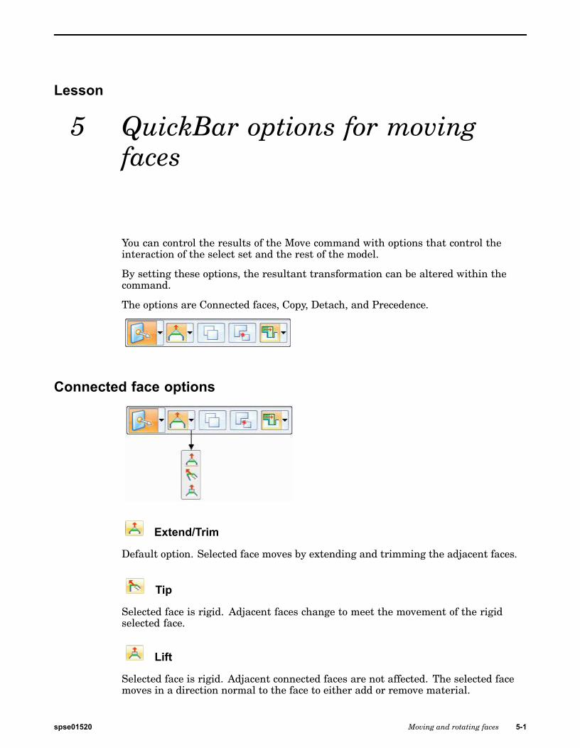
You can control the results of the Move command with options that control theinteraction of the select set and the rest of the model.
By setting these options, the resultant transformation can be altered within thecommand.
The options are Connected faces, Copy, Detach, and Precedence.
Connected face options
Extend/Trim
Default option. Selected face moves by extending and trimming the adjacent faces.
Tip
Selected face is rigid. Adjacent faces change to meet the movement of the rigidselected face.
Lift
Selected face is rigid. Adjacent connected faces are not affected. The selected facemoves in a direction normal to the face to either add or remove material.
spse01520 Moving and rotating faces 5-1

Lesson 5 QuickBar options for moving faces
Copy
The copy option creates a copy of the faces in the select set.
The faces are collected into a face set feature.
The face set feature can be moved or rotated.
This option is similar to a copy and paste operation.
The original selected faces are unchanged.
Activity: Copying and attaching a feature (method 1)
The activity guides you through the process of copying a cutout feature and thenattaching the copied feature at a new location on the model.
Turn to Appendix E for the activity.
Activity: Copying and attaching a feature (method 2)
This activity has the same goal as method 1, but. uses a different approach.
Turn to Appendix F for the activity.
5-2 Moving and rotating faces spse01520

QuickBar options for moving faces
Activity: Copying, rotating, and attaching a feature to a new location
This activity guides you through the process of copying a feature, aligning thefeature to an angled face, and then positioning the feature on the model. Twomethods are used in the activity.
Turn to Appendix H for the activity.
Detach
The detach option removes the select set from the part body.
The removed select set can be moved or rotated.
This option is similar to a cut and paste operation.
spse01520 Moving and rotating faces 5-3

Lesson 5 QuickBar options for moving faces
Activity: Detaching and attaching a feature
The activity guides you through the process of detaching an extruded feature andthen attaching the copied feature at a new location on the model.
Turn to Appendix G for the activity.
Precedence
The precedence option is used to set which face(s) have priority during a synchronousmove operation.
Select Set Priority
Selected and other moving faces have priority over non-moving faces.
Model Priority
Non-moving faces have priority over moving faces.
5-4 Moving and rotating faces spse01520

Lesson
6 Working with Live Sections
You use the Live Section command to create a 2D cross-section on a plane througha 3D part. For example, you can select one of the principal planes on the basecoordinate system as the plane for a live section.
Live sections can make it easier to visualize and edit certain types of parts, such asparts that contain revolved features. You can then edit the 2D elements of the livesection to modify 3D model geometry.
spse01520 Moving and rotating faces 6-1
Lesson 6 Working with Live Sections
Creating live sections
You can select a planar face, reference plane, or principal plane on a coordinatesystem as the plane for the live section. When you select the plane, a live section iscreated, similar to a section view in a drawing. When the live section passes througha procedural feature, such as a hole, an edge set is created.
An entry for the live section is added to the Live Sections collector in PathFinder.
Editing live sections
You edit a live section using the Select tool and the 2D steering wheel editing handle.You can edit individual elements or you can edit the entire live section.
Editing 2D elements in a live section to modify the 3D model
When you select a 2D element in a live section, the 2D steering wheel editingtool is displayed. You can use the handles on the 2D steering wheel to move orrotate the live section element to modify 3D model geometry. If the live sectionelement you select is an edge set created from a procedural feature, such as ahole, the editing handle for the procedural feature is also displayed.
You can also place PMI dimensions on the 2D elements of a live section and thenedit the dimension value to modify the model.
Note
When moving a live section element using the 2D steering wheel edittool or a PMI dimension, the current settings in Live Rules are used tocontrol the edit behavior.
Editing the entire live section
You can select the entire live section using PathFinder or QuickPick. You canthen use the steering wheel to move or rotate the entire live section. When youmove or rotate the entire live section, 3D model geometry is not modified. Thelive section recalculates at its new position. This can be useful when you havemodified the 3D model using other methods, such that the live section is nolonger positioned where you want it.
Displaying live sections
You can use the check box adjacent to a live section entry in PathFinder to show orhide a live section in the graphics window. You can use the check box adjacent to theLive Sections collector to display or hide all the live sections.
You can use the Live Section Colors section on the Colors page of the Solid EdgeOptions dialog box to specify the colors you want to use for the edges, centerlines,and regions for live sections.
6-2 Moving and rotating faces spse01520

Working with Live Sections
Model editing and live section update
The live section automatically updates when you add or remove features, or directlyedit the 3D model. For example, if you add a pattern of holes to a synchronous model,the live section automatically updates.
Live sections in an assembly
You can edit a 2D element on a live section to modify a part in the context of anassembly. You can use the keypoints on adjacent parts to modify the live sectionelement with respect to other parts in the assembly.
You can use commands on the shortcut menu to control the display of live sectionson a selected part.
Activity: Live SectionThis activity guides you through the process of creating a live section through amodel. The model is modified by manipulating the live section edges.
Turn to Appendix I for the activity.
spse01520 Moving and rotating faces 6-3

A Activity: Moving androtating faces
Open activity file
▸ Open move_01.par.
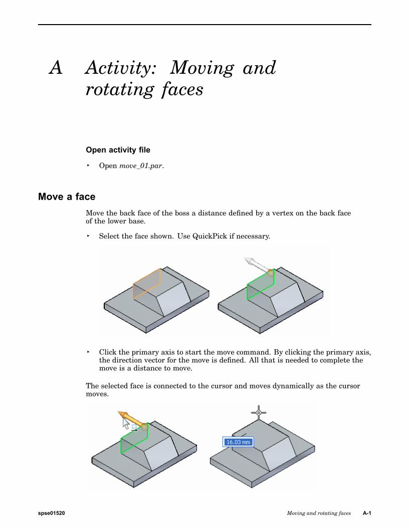
Move a faceMove the back face of the boss a distance defined by a vertex on the back faceof the lower base.
▸ Select the face shown. Use QuickPick if necessary.
▸ Click the primary axis to start the move command. By clicking the primary axis,the direction vector for the move is defined. All that is needed to complete themove is a distance to move.
The selected face is connected to the cursor and moves dynamically as the cursormoves.
spse01520 Moving and rotating faces A-1

A Activity: Moving and rotating faces
▸ Use a keypoint locate to define the move to distance. On the Move QuickBar,select the All keypoints option.
▸ Move the cursor over the corner shown and click when the endpoint appears.
▸ Press the Esc key to end the move command.
A-2 Moving and rotating faces spse01520

Activity: Moving and rotating faces
Move faces▸ Move the side faces on the boss a distance defined by a vertex on the side face
of the lower base.
Rotate a face▸ Select the angled face.
spse01520 Moving and rotating faces A-3

A Activity: Moving and rotating faces
▸ To rotate the selected face, a rotation axis needs to be defined. Drag the steeringwheel origin to the edge shown. The secondary axis must lie on an edge that theface will rotate about.
▸ Click the steering wheel torus to start the rotation. As the cursor moves, therotation angle tracks with the cursor. Type 35 in the input box to define therotation angle.
▸ Press the Esc key to end the command.
▸ This ends the activity. Exit the file and do not save.
SummaryIn this activity you learned how to move and rotate faces. You can define distancesto move by dragging and clicking, typing in a distance, or by using keypoints. Torotate a face, position the secondary axis of the steering wheel on an edge to rotateabout. Click the torus and move the cursor to define the rotation angle or type arotation angle in the edit box.
A-4 Moving and rotating faces spse01520

B Activity: Copying a face andusing keypoints to definemovement
Open activity file
▸ Open move_02.par.
Select the hole to copy▸ Select the cylindrical face shown.
▸ In QuickBar, click the copy option.
spse01520 Moving and rotating faces B-1

B Activity: Copying a face and using keypoints to define movement
Define the move from pointAt this point, the steering wheel origin is at the center of the selected cylindricalface. Move the origin to the top left hole.
▸ Click the steering wheel origin and then move the cursor to the upper left hole.Click when the origin locks to the center of the hole. You may have to zoom in ifyou have trouble locking to the center of the hole.
B-2 Moving and rotating faces spse01520

Activity: Copying a face and using keypoints to define movement
Define the move direction▸ Click the primary knob shown. This controls the primary axis direction.
▸ Move the cursor over the cylindrical face shown, and click when the center pointsymbol appears.
spse01520 Moving and rotating faces B-3

B Activity: Copying a face and using keypoints to define movement
▸ Notice that the primary axis now points to the center of the hole. Directiondefinition is complete.
Define the move distance▸ Click the primary axis to start the Move command.
B-4 Moving and rotating faces spse01520

Activity: Copying a face and using keypoints to define movement
▸ Make sure the keypoints option in QuickBar is set to All or Center Point.
spse01520 Moving and rotating faces B-5

B Activity: Copying a face and using keypoints to define movement
▸ Click the center of the hole shown. This defines the move distance. Click againto end the command.
Verify move distance▸ Measure the copied distance. On the Inspect tab, in the 3D Measure group,
choose the Measure Distance command .
▸ Measure the distance between the top two holes. Click when the center pointhighlights. Notice the minimum distance and then click Reset in the commandbar. The distance is 14 mm.
B-6 Moving and rotating faces spse01520
Activity: Copying a face and using keypoints to define movement
▸ Measure the distance between the lower two holes. The distance between theholes should also be 14 mm.
▸ This ends the activity. Exit the file and do not save.
SummaryIn this activity you learned how to use the 3D steering wheel to control a moveor copy operation. You learned how to redefine an origin point (move from point)and how to modify the direction of a move. You used face keypoints to define themove/copy direction and distance.
spse01520 Moving and rotating faces B-7


C Activity: Using the SelectionManager
Open activity file
▸ Open select_b.par.
Select all rounds of equal radiusUse selection manager to select all rounds of equal radius and change the radiusvalue for all the rounds selected.
▸ Select the round shown below.
▸ Move cursor over round to display the green dot.
Note
If the green dot does not display, move the steering wheel or zoom in.
▸ Click the green dot to display the selection manager. Make sure Use BoxSelection is not checked.
spse01520 Moving and rotating faces C-1

C Activity: Using the Selection Manager
▸ On the Selection Manager, click the Equal Radius option. Notice that allrounds that have the same radius (1.524) are added to the select set.
Change the round radius▸ Select the PMI dimension on the round.
C-2 Moving and rotating faces spse01520

Activity: Using the Selection Manager
▸ In the dimension box, type 2 and then press the Enter key. Press Esc to clearthe select set. All rounds in the select set are now equal to 2.
Use the selection boxAdd rounds to a select set using a selection box.
▸ Select the round shown.
▸ Bring up the Selection Manager and then click Use Selection Box.
▸ In Selection Manager, click Equal Radius.
spse01520 Moving and rotating faces C-3
C Activity: Using the Selection Manager
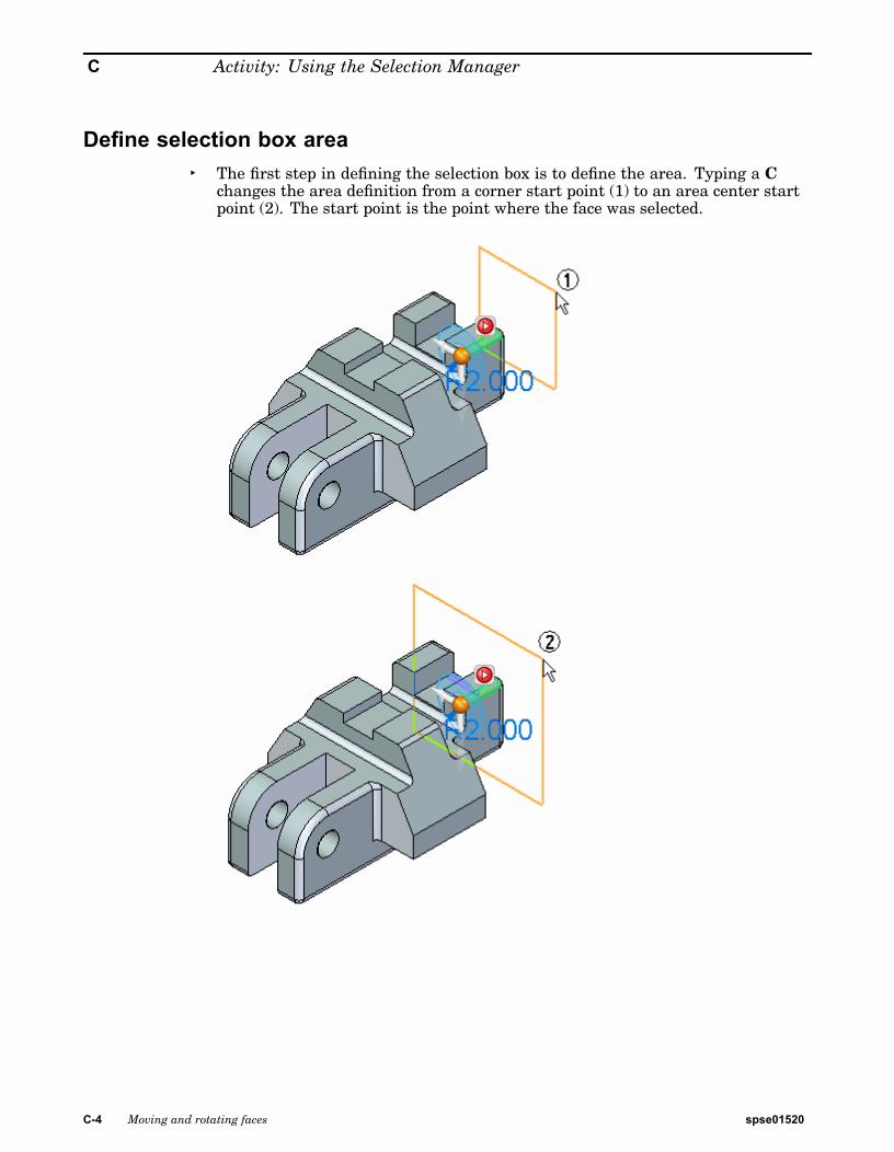
Define selection box area▸ The first step in defining the selection box is to define the area. Typing a C
changes the area definition from a corner start point (1) to an area center startpoint (2). The start point is the point where the face was selected.
C-4 Moving and rotating faces spse01520

Activity: Using the Selection Manager
Use the center option and define an area as shown.
Define select box depth▸ The next step is to define the select box depth. Typing an S changes the
definition from a side definition (1) to a symmetric definition (2). Side stepdefines depth in either direction (1) normal to the defined area. The symmetricoption defines the depth symmetric (2) about the defined area.
Define a symmetric depth as shown.
Note
You can rotate the view to better view the positioning of the area and thedepth of the selection box.
Change radius of select set
spse01520 Moving and rotating faces C-5

C Activity: Using the Selection Manager
▸ Edit the radius to 3.
▸ Press the Esc key to clear the select set.
▸ This completes the activity.
SummaryIn this activity you learned how to use the Selection Manager to control the selectionprocess. With practice you will master the use of the box selection.
C-6 Moving and rotating faces spse01520

D Activity: Modifying a part bymoving select sets
Open activity file
▸ Open select_a.par.
Suspend Live RulesSince the Live Rules topic has not been covered, turn off live rules.
▸ A face must be selected for Live Rules to appear. Click on any face.
▸ On the Live Rules panel, click the Suspend Live Rules (1) check box.
Select feature to moveMove protrusion feature to other end of part.
▸ To select the feature to move, first select the face shown.
At this point, only the selected face would move.
spse01520 Moving and rotating faces D-1

D Activity: Modifying a part by moving select sets
▸ Move the cursor over the face until the green dot displays.
▸ Move the cursor over the green dot and the red arrow displays. Click the redarrow to display the Selection Manager.
▸ In the Selection Manager, click Sets. This will find any sets that contain theselected face.
▸ QuickPick displays the sets found. Click the Protrusion entry displayed inQuickPick.
▸ The feature is selected and will participate in the move operation.
D-2 Moving and rotating faces spse01520

Activity: Modifying a part by moving select sets
Move the feature▸ Click the primary axis on the steering wheel and move the feature to the other
side of the channel-shaped feature.
▸ Move the feature to the approximate location and click. The move from pointis the origin on the graphic handle.
▸ Move complete. Press the Esc key to clear the select set.
spse01520 Moving and rotating faces D-3

D Activity: Modifying a part by moving select sets
Select the channel-shaped feature▸ Select the face shown.
▸ In the Selection Manager, click Recognize ® Rib/Boss.
The Sets option would work here also.
D-4 Moving and rotating faces spse01520

Activity: Modifying a part by moving select sets
Move the channel-shaped feature▸ Click the primary axis on the steering wheel and move the select set to the edge
of the part. Use a keypoint on the edge of the part to define distance to move.The keypoint option is on QuickBar (3).
Extend the legs of the channel-shaped feature▸ Select the two faces shown.
spse01520 Moving and rotating faces D-5
D Activity: Modifying a part by moving select sets
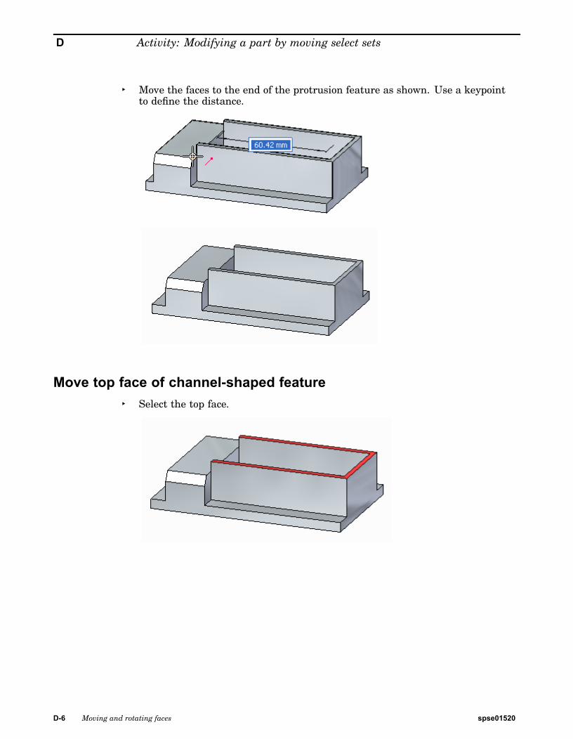
▸ Move the faces to the end of the protrusion feature as shown. Use a keypointto define the distance.
Move top face of channel-shaped feature▸ Select the top face.
D-6 Moving and rotating faces spse01520

Activity: Modifying a part by moving select sets
▸ Move the top face to the top of the protrusion feature.
Move protrusion feature to end of part▸ Select the protrusion feature.
spse01520 Moving and rotating faces D-7

D Activity: Modifying a part by moving select sets
▸ Move the select set to end of part.
▸ This ends the activity. Exit the file and do not save.
SummaryIn this activity you learned how to create select sets for a move operation. Live Ruleswere suspended for the activity. After the live rules topic is covered, you will be ableto perform the same part modifications in other ways.
D-8 Moving and rotating faces spse01520

E Activity: Copying and attachinga feature (method 1)
Open activity file
▸ Open copy_a.par.
Select the feature to copy▸ Select the cutout feature by clicking Cutout1 in PathFinder.
▸ Position the 3D steering wheel as shown.
spse01520 Moving and rotating faces E-1

E Activity: Copying and attaching a feature (method 1)
Suspend Live RulesLive Rules is covered in theWorking with face relationships self-paced course.Suspend the Live Rules settings while moving the cutout feature. This ensures noother faces in the model participate in the move.
▸ Click the Suspend Live Rules (1) check box.
Set the copy option and move the feature▸ On QuickBar, click the Copy option.
E-2 Moving and rotating faces spse01520

Activity: Copying and attaching a feature (method 1)
▸ Move the copied feature to the face shown in orange.
To begin the move, click the secondary axis shown. The move origin point iswhere the origin of the steering wheel is located.
Define the move distance and direction▸ Move the feature to the edge of the part using a keypoint. On QuickBar, click
the keypoints drop list arrow and select Endpoint.
spse01520 Moving and rotating faces E-3

E Activity: Copying and attaching a feature (method 1)
▸ Select the keypoint location shown.
Change move direction▸ The primary axis should point down. If your steering wheel position is different,
change the move direction by clicking the cardinal point (3) on the steeringwheel and then click the primary axis.
E-4 Moving and rotating faces spse01520

Activity: Copying and attaching a feature (method 1)
▸ Select the keypoint.
Move by keying in a distance▸ Click the secondary axis.
spse01520 Moving and rotating faces E-5

E Activity: Copying and attaching a feature (method 1)
▸ Type 10 in dynamic edit box.
E-6 Moving and rotating faces spse01520

Activity: Copying and attaching a feature (method 1)
Attach the copied featureThe copied feature is now positioned but is detached from the model.
▸ Right-click in the part window and click Attach.
SummaryIn this activity you learned how to copy a feature and then position the copiedfeature. There are other methods available to move the copied feature to a locationother than what was shown in this activity.
spse01520 Moving and rotating faces E-7


F Activity: Copying and attachinga feature (method 2)
Open activity file
▸ Open copy_b.par.
Suspend Live RulesLive Rules is covered in the Working with geometric relationships self-pacedcourse. Suspend the Live Rules settings while moving the cutout feature. Thisensures no other faces in the model participate in the move.
▸ Click the Suspend Live Rules (1) check box.
Select the feature to copy▸ Select the cutout feature by clicking Cutout1 in PathFinder.
spse01520 Moving and rotating faces F-1

F Activity: Copying and attaching a feature (method 2)
▸ Position the 3D steering wheel as shown.
Set the copy option and move the feature▸ On QuickBar, click the Copy option.
▸ Move the copied feature to the face shown in orange.
F-2 Moving and rotating faces spse01520

Activity: Copying and attaching a feature (method 2)
Relocate the steering wheel originIn this activity, the steering wheel plane is used to move the copied feature insteadof the secondary axis used in the method 1 activity.
▸ To relocate the steering wheel origin, hold the Shift key down, and drag thesteering wheel origin to the midpoint of the face edge (4). As you drag along theface edge (4), notice that the steering wheel origin jumps to the midpoint of edge(4). When you hold the Shift key down to move the steering wheel origin, thesteering wheel orientation remains fixed.
The move is from the midpoint of edge (4) to the midpoint of edge (5).
Move the copied feature using the steering wheel plane▸ Click the steering wheel tool plane.
spse01520 Moving and rotating faces F-3

F Activity: Copying and attaching a feature (method 2)
▸ Drag the cursor over the edge shown and click when the midpoint symboldisplays. You may have to turn on the midpoint option on QuickBar.
▸ Press the Esc key to end the move command.
Note
Since this copy operation was accomplished in one movement, the copiedfeature attaches automatically.
SummaryIn this activity you learned how to copy a feature and then position the copiedfeature by moving the steering wheel origin and using the steering wheel plane todefine the move vector.
F-4 Moving and rotating faces spse01520

G Activity: Detaching andattaching a feature
Open activity file
▸ Open detach_a.par.
Suspend Live RulesLive Rules is covered in the Working with geometric relationships self-pacedcourse. Suspend the Live Rules settings while moving the feature. This ensures noother faces in the model participate in the move.
▸ Click the Suspend Live Rules (1) check box.
spse01520 Moving and rotating faces G-1

G Activity: Detaching and attaching a feature
Select the feature to detach▸ In PathFinder, click the feature named Protrusion 2.
Position the steering wheel origin▸ Drag the steering wheel origin to the midpoint of the edge shown.
Move the feature▸ On QuickBar, click the detach option.
G-2 Moving and rotating faces spse01520

Activity: Detaching and attaching a feature
▸ Click the steering wheel tool plane to start the move.
▸ Select the midpoint of the edge shown to complete the move.
spse01520 Moving and rotating faces G-3

G Activity: Detaching and attaching a feature
Attach the feature▸ Right-click in the part window and choose the Attach command.
SummaryIn this activity you learned how to detach a feature, move it to a new location, andthen attach the feature to the model. This process is similar to a cut and pasteprocess.
G-4 Moving and rotating faces spse01520

H Activity: Copying, rotating,and attaching a feature toa new location
Open activity file
▸ Open rotate.par.
Suspend Live RulesLive Rules is covered in the Working with geometric relationships self-pacedcourse. Suspend the Live Rules settings while moving the feature. This ensures noother faces in the model participate in the move.
▸ Click the Suspend Live Rules (1) check box.
spse01520 Moving and rotating faces H-1

H Activity: Copying, rotating, and attaching a feature to a new location
Method one overviewYou will use the copy option on QuickBar. Align the feature using the Relatecommand. Position the feature using the steering wheel. Copy feature (1) onto face(2). Center feature on face (2) with the feature holes aligned to the midpoint ofedge (3).
Select the feature▸ In PathFinder, select the feature named Protrusion 1.
▸ On QuickBar, click the copy option.
H-2 Moving and rotating faces spse01520

Activity: Copying, rotating, and attaching a feature to a new location
Move the copied feature▸ Position the steering wheel as shown and click the primary axis to start the
move command.
▸ In the dynamic edit box, type 125 and press the Enter key.
spse01520 Moving and rotating faces H-3

H Activity: Copying, rotating, and attaching a feature to a new location
Align the feature to the angled face▸ On QuickBar, choose the Relate command.
Note
The Relate command is covered in the Working with face relationshipscourse. We will use the command to change the angle of the copied feature.You could use the steering wheel to rotate the feature but you need toknow the angle of the face. The Relate command is an easier step.
Use the Parallel relationship.
▸ Select the angled face.
H-4 Moving and rotating faces spse01520

Activity: Copying, rotating, and attaching a feature to a new location
▸ Click the Accept button on QuickBar and then press the Esc key.
The feature is now aligned with the angled face.
Position the feature▸ Move the steering wheel origin to the center of one of the cylindrical faces as
shown.
▸ Click the cardinal point shown to define the move direction.
spse01520 Moving and rotating faces H-5

H Activity: Copying, rotating, and attaching a feature to a new location
▸ Click the secondary axis and then select the midpoint of the edge shown.
Note
If you cannot locate the midpoint on the edge, make sure the All keypointsoption is set.
H-6 Moving and rotating faces spse01520

Activity: Copying, rotating, and attaching a feature to a new location
▸ Move the steering wheel origin to any point on the bottom of the feature.
▸ Click the primary axis and then select the endpoint shown.
spse01520 Moving and rotating faces H-7

H Activity: Copying, rotating, and attaching a feature to a new location
Attach the feature▸ Right-click in the part window and choose Attach.
This completes the first method of copying, aligning, and positioning a feature.
H-8 Moving and rotating faces spse01520

Activity: Copying, rotating, and attaching a feature to a new location
Method two overviewYou will use the Copy to and Paste from clipboard commands. Use the short-cutkeys Ctrl+C (copy) and Ctrl+V (paste). Align the feature using the F3 key. Positionthe feature using the steering wheel. Copy feature (1) onto face (4). Center featureon face (4) with the feature holes aligned to the midpoint of edge (3).
To copy a selected feature to the clipboard, press Crtl+C.
To paste a feature from the clipboard, press Crtl+V.
You can also choose the commands from the Clipboard group.
Select the feature to copy▸ In PathFinder, select the feature named Protrusion 1.
▸ Position the steering wheel origin at any point on the bottom of the feature. Thiscomes into play when the feature is aligned to the target angled face. Make surethe secondary axis points in the direction shown.
spse01520 Moving and rotating faces H-9

H Activity: Copying, rotating, and attaching a feature to a new location
Copy and paste feature▸ Press Ctrl+C to copy the selected feature to the clipboard.
▸ Press Ctrl+V to paste the feature. The feature is attached to the cursor.
▸ Drag the cursor over the face shown.
▸ Press the F3 key to coplanar align the steering wheel face to the angled face.This is the reason you positioned the steering wheel to a point on the bottom ofthe feature in an earlier step.
H-10 Moving and rotating faces spse01520

Activity: Copying, rotating, and attaching a feature to a new location
▸ Click to place the feature.
Rotate the feature▸ Click the steering wheel torus.
spse01520 Moving and rotating faces H-11

H Activity: Copying, rotating, and attaching a feature to a new location
▸ In the dynamic edit box, type 90 and then press the Enter key.
H-12 Moving and rotating faces spse01520

Activity: Copying, rotating, and attaching a feature to a new location
Center the feature on the face▸ Move the steering wheel origin to the midpoint of a linear edge on the feature
and click the secondary axis point shown to define the move direction.
spse01520 Moving and rotating faces H-13

H Activity: Copying, rotating, and attaching a feature to a new location
▸ Click the midpoint on the edge shown.
H-14 Moving and rotating faces spse01520
Activity: Copying, rotating, and attaching a feature to a new location
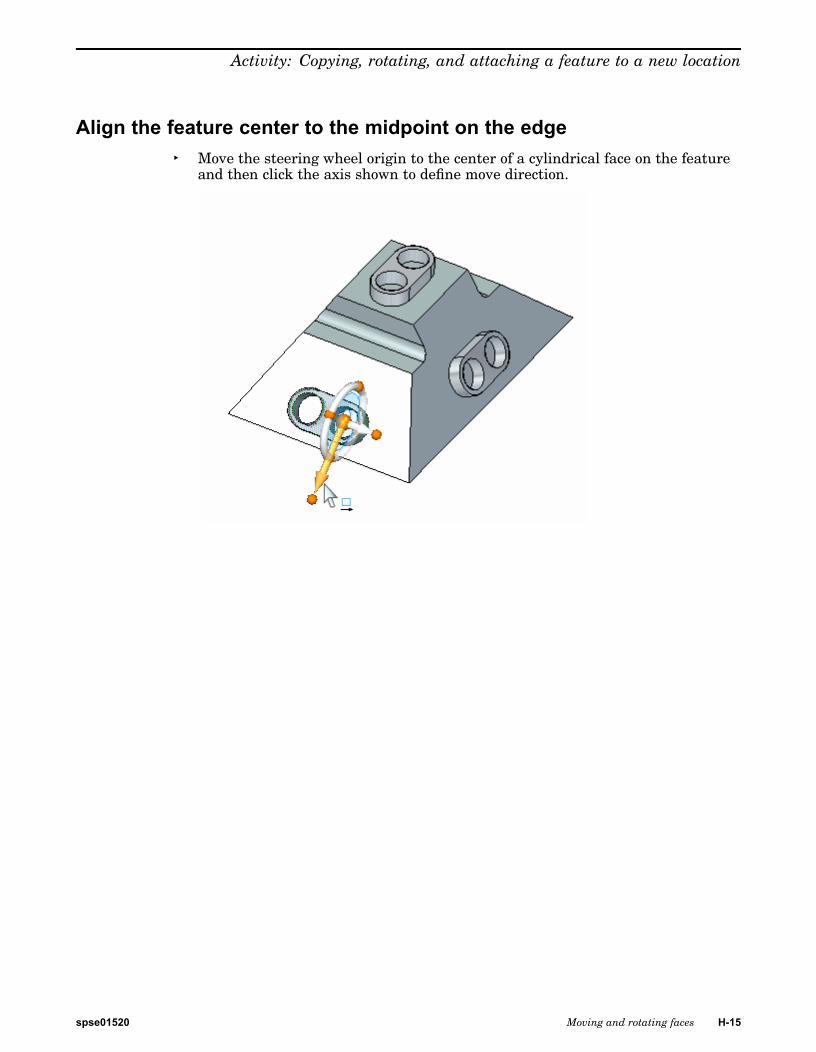
Align the feature center to the midpoint on the edge▸ Move the steering wheel origin to the center of a cylindrical face on the feature
and then click the axis shown to define move direction.
spse01520 Moving and rotating faces H-15

H Activity: Copying, rotating, and attaching a feature to a new location
▸ Click the midpoint of the edge.
Attach the feature to the model▸ Right-click in the part window and choose Attach.
This completes the activity.
H-16 Moving and rotating faces spse01520

Activity: Copying, rotating, and attaching a feature to a new location
SummaryIn this activity you learned how to copy, align, and position a feature. Two methodswere shown to help you understand the available tools for copying geometry.
spse01520 Moving and rotating faces H-17


I Activity: Live Section
Open activity file
▸ Open live_section.par.
Create a section plane▸ In the Planes group, choose the Coincident Plane command.
▸ Select the plane shown.
spse01520 Moving and rotating faces I-1

I Activity: Live Section
▸ Move the coincident plane to the midpoint of the edge shown.
Create a Live Section
▸ In the Section group, choose the Live Section command .
I-2 Moving and rotating faces spse01520
Activity: Live Section
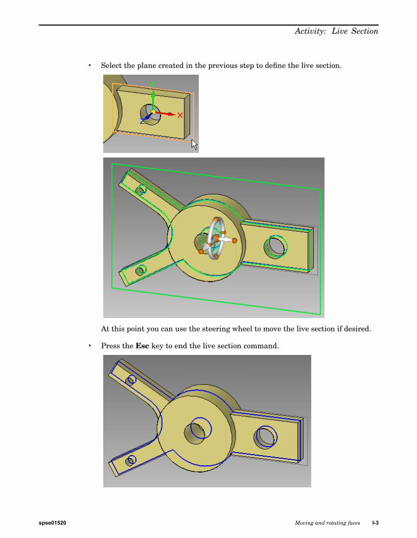
▸ Select the plane created in the previous step to define the live section.
At this point you can use the steering wheel to move the live section if desired.
▸ Press the Esc key to end the live section command.
spse01520 Moving and rotating faces I-3

I Activity: Live Section
▸ Notice in PathFinder that a Live Sections collector is created. The display ofa live section can be controlled with the check box.
Move a faceInstead of selecting a face to move, the edge created by the section through a facecan be selected to move. Moving the edge is the same as moving the face.
▸ Select the edge shown and move it to observe the behavior.
Dynamically move the face but do not click. Press Esc to end the move. PressEsc again to clear the selected edge.
Note
The edge can take on all operations that its parent face can (for example:dimension, rotate, delete).
Modify the model shape by manipulating the live sectionThe model does not have to be displayed to manipulate a live section. Turn off thedisplay of the model.
I-4 Moving and rotating faces spse01520

Activity: Live Section
▸ Right-click in the part window and on the shortcut menu click Hide All ®®®Design Body. Hide all reference planes too.
▸ Change the display to a front view. Press Ctrl+F.
spse01520 Moving and rotating faces I-5

I Activity: Live Section
▸ Rotate the two arms on the left 15° about the center hole. Select the live sectionedges shown. Use a fence as shown.
I-6 Moving and rotating faces spse01520

Activity: Live Section
▸ Move the steering wheel origin to the center of the hole as shown.
▸ Change the orientation of steering wheel. Click the cardinal point shown andthen click the midpoint of the right edge.
spse01520 Moving and rotating faces I-7

I Activity: Live Section
▸ Click the torus. Type 15 and press the Enter key.
▸ Press the Esc key to end the move command.
I-8 Moving and rotating faces spse01520

Activity: Live Section
Observe model changes▸ Change to a dimetric view.
▸ On the shortcut menu, turn on the display of the Design Body. Notice that themodel has changed to the modifications made to the live section.
spse01520 Moving and rotating faces I-9

I Activity: Live Section
Delete a face▸ Click the circular edge shown and press the Delete key.
Deleting the live section circular edge is the same as deleting the circular face.
Remove material to create a slot▸ Turn off the design body display.
I-10 Moving and rotating faces spse01520

Activity: Live Section
▸ Draw a sketch containing two lines and one arc. Choose the Line command andclick the right section edge.
spse01520 Moving and rotating faces I-11

I Activity: Live Section
▸ Align the circle center with the midpoint of the right edge.
▸ Select the region shown.
▸ On QuickBar, click (2) to set the Remove material option. Click (1) to set theThrough All extent option.
I-12 Moving and rotating faces spse01520

Activity: Live Section
▸ Click the origin on the handle to make sure the arrows point in both directions.
Change display to observe the changes▸ Turn on the design body.
spse01520 Moving and rotating faces I-13

I Activity: Live Section
▸ In PathFinder, turn off the live section display.
This completes the activity.
SummaryIn this activity you learned how to create a live section. The live section commandcreates edges where a user defined plane intersects the design body. Each livesection edge represents a face in the model. You can select either the face or livesection edge to modify the model.
I-14 Moving and rotating faces spse01520

J Activity: Reorient the steeringwheel
Overview
Examine the components used for reorienting the steering wheel. In this activity, ageometric feature is moved using the steering wheel. The steering wheel is orientedto define the move direction.
Open activity file
▸ Open steering_wheel.par.
Move geometry in the primary and secondary axes directionsNote
A move in the primary axis direction occurs on the steering wheel plane. Amove in the secondary axis direction is normal to the steering wheel plane.
Note
A move occurs between the move from point to the move to point. Themove from point is always the steering wheel origin. Themove to point canbe a keypoint, user-defined typed distance, or a drag and click location.
▸ In PathFinder, select the feature named feature A.
spse01520 Moving and rotating faces J-1

J Activity: Reorient the steering wheel
▸ Click the primary axis. As you drag the cursor up and down, notice the featuremoves in a direction defined by the primary axis.
At this point, you can drag and click to define the move distance, type a distancevalue in dynamic edit box, or click on a geometric keypoint.
▸ Press the Esc key to end the move.
▸ Click the secondary axis. As you drag the cursor, notice the feature moves in adirection defined by the secondary axis.
▸ Press the Esc key to end the move.
J-2 Moving and rotating faces spse01520

Activity: Reorient the steering wheel
Change the direction of the primary axisNote
You can change the primary axis direction in 90° increments by clickinga cardinal point.
Note
You can change the primary axis direction at a user-defined point or a dragand click point to define direction angle
▸ Hold the Shift key and click the primary knob.
spse01520 Moving and rotating faces J-3

J Activity: Reorient the steering wheel
▸ Move feature A at a 45° direction angle. Once the angle is set, click the primaryaxis to start the move. The right portion of the image shows a front view tobetter visualize the 45° movement.
▸ Press the Esc key to end the move.
Move geometry in the steering wheel planeYou can perform a free move to any point on the steering wheel plane. You clickthe steering wheel plane and drag the selected geometry to a desired location andthen click, or select a geometric keypoint.
▸ Select feature A.
▸ Click the steering wheel plane. Drag the feature around and notice that themovement is locked to the steering wheel plane.
▸ Press the Esc key to end the move.
J-4 Moving and rotating faces spse01520
Activity: Reorient the steering wheel
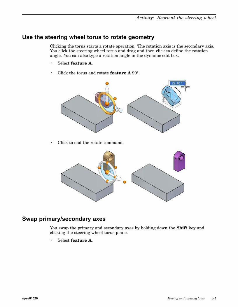
Use the steering wheel torus to rotate geometryClicking the torus starts a rotate operation. The rotation axis is the secondary axis.You click the steering wheel torus and drag and then click to define the rotationangle. You can also type a rotation angle in the dynamic edit box.
▸ Select feature A.
▸ Click the torus and rotate feature A 90°.
▸ Click to end the rotate command.
Swap primary/secondary axesYou swap the primary and secondary axes by holding down the Shift key andclicking the steering wheel torus plane.
▸ Select feature A.
spse01520 Moving and rotating faces J-5

J Activity: Reorient the steering wheel
▸ Hold down the Shift key and click the steering wheel plane.
Note
This is a quick method of changing the rotation axis.
▸ Press the Esc key.
Change the direction of the primary/secondary axes using a geometrickeypoint
You can change the direction of the primary or secondary axis by clicking the axisknob and then selecting a geometric keypoint.
▸ Select feature A.
J-6 Moving and rotating faces spse01520

Activity: Reorient the steering wheel
▸ Reposition the move from point. Select the steering wheel origin and then dragthe origin to the corner of the selected feature shown.
You want to move the feature to corner 1. Define the direction axis pointing tocorner 1.
▸ Click the primary axis knob. Move the cursor over corner 1 and click whenthe endpoint displays.
spse01520 Moving and rotating faces J-7

J Activity: Reorient the steering wheel
▸ Click the primary axis and notice the direction of movement.
At this point if you click the endpoint shown, the feature would move to thatpoint.
▸ Press the Esc key twice to cancel the operation.
Maintain a steering wheel orientation at a different locationIf you want to maintain a steering wheel orientation at a different location, youhold the Shiftkey down, click the steering wheel origin, and drag it to the desiredlocation. If the origin is close to a keypoint, it will snap to that point. Click toposition origin to that point.
▸ Select feature A.
▸ Hold the Shiftkey down and click the steering wheel origin.
▸ Drag the steering wheel origin over the model (at the corners and edgemidpoints) and notice that the steering maintains the orientation.
If you repeat the same step without holding down the Shift key, the steeringwheel orientation changes as it passes over the model edges, corners and faces.
J-8 Moving and rotating faces spse01520
Activity: Reorient the steering wheel
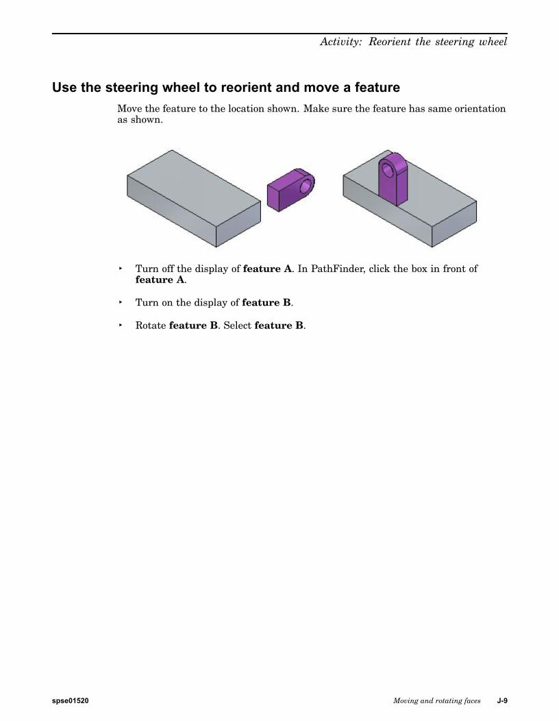
Use the steering wheel to reorient and move a featureMove the feature to the location shown. Make sure the feature has same orientationas shown.
▸ Turn off the display of feature A. In PathFinder, click the box in front offeature A.
▸ Turn on the display of feature B.
▸ Rotate feature B. Select feature B.
spse01520 Moving and rotating faces J-9

J Activity: Reorient the steering wheel
▸ Click the torus, type 90 in the dynamic edit box, and then click.
J-10 Moving and rotating faces spse01520

Activity: Reorient the steering wheel
▸ Rotate the feature again to complete the orientation. Position the steering wheelorigin as shown. Click the torus. Drag and type either 90 or -90 in the dynamicedit box (note the plus or minus value in the dynamic edit box to determine if 90or -90 should be entered). Press the Tab key and then click.
spse01520 Moving and rotating faces J-11

J Activity: Reorient the steering wheel
▸ Move the feature to new location. Select feature A. Position the steering wheelorigin as shown (midpoint of edge). Define the primary axis direction to pointto the edge midpoint on part. Click the primary axis to start the move. Movethe cursor over the edge midpoint and click when the midpoint highlights. PressEsc to end the move operation.
▸ Try positioning the feature at other locations on the part.
SummaryIn this activity you learned how to reorient the steering wheel to accomplish desiredmove and rotate operations.
J-12 Moving and rotating faces spse01520