Movements Tolerances - Karolkarol.us/articles/movements and tolerances.pdf · cladding from the...
12
46 The Construction Specifier October 2008 by Karol Ka´ zmierczak, CSI, CDT, AIA, ASHRAE, NCARB, LEED AP A s difficult as it is for some to imagine, buildings move. The introduction of curtain walls gave buildings even more freedom to move, with the peaceful rigidity of bulky bearing walls and relatively short spans of oversized structural members now a thing of the past. The biggest single difference between having windows punched into load-bearing walls and having a curtain wall lies in the mechanisms needed for the latter to accommodate movements—both between cladding and structure and among cladding components themselves (Figure 1). While movements are induced by the same live loads as always (e.g. users, wind, seismic, and temperature/moisture fluctuations), components of a modern building respond differently from older structures for several reasons. Material use has become more economical, yielding higher deflections. At the same time, the practice of thermally isolating the cladding from the body of the building has led to greater temperature differentials, and the materials (i.e. metals and plastics) have become more volatile—changing in volume size more than older, traditional materials. Since a tolerance potentially narrows the interface joints, it entails almost the same effect as a movement, from the façade designer’s perspective. Joinery and support of cladding has to accommodate all cumulative movements, as well as potential dimensional deviations of components as built and installed. Construction tolerances are not driven by their eventual compatibility, but by production limitations. In other words, specification of a set of ‘standard’ tolerances does not ensure compatibility and proper functioning of the design. Specifiers should be aware of this, and coordinate tolerances of adjacent trades for compatibility. The production tolerances should be clearly distinguished from those for erection, and they should ideally be non-cumulative. (The former should be specified in Part 2−Products, the latter in Part 3−Execution of each specification section.) To add to the potential problems with curtain walls, glazing frequently becomes the aesthetic focus of the façade, entailing visual scrutiny (Figure 2). While modern glazing is built with a level of precision that meets the demands of the human eye, it remains in a sharp disparity with precision of other trades. Considerations for curtain wall and cladding design Considerations for curtain wall and cladding design & Movements Tolerances ©Image from BigStockPhoto.com CS-October-08-b.indd 46 CS-October-08-b.indd 46 9/11/08 1:00:57 PM 9/11/08 1:00:57 PM
Transcript of Movements Tolerances - Karolkarol.us/articles/movements and tolerances.pdf · cladding from the...

46 The Construction Specifi er October 2008
by Karol Kazmierczak, CSI, CDT, AIA, ASHRAE, NCARB, LEED AP
As diffi cult as it is for some to imagine, buildings move. The introduction of curtain walls gave buildings even more freedom to move, with the peaceful rigidity of bulky bearing walls and relatively short spans of
oversized structural members now a thing of the past. The biggest single difference between having windows punched into load-bearing walls and having a curtain wall lies in the mechanisms needed for the latter to accommodate movements—both between cladding and structure and among cladding components themselves (Figure 1).
While movements are induced by the same live loads as always (e.g. users, wind, seismic, and temperature/moisture fl uctuations), components of a modern building respond differently from older structures for several reasons. Material use has become more economical, yielding higher defl ections. At the same time, the practice of thermally isolating the cladding from the body of the building has led to greater temperature differentials, and the materials (i.e. metals and plastics) have become more volatile—changing in volume size more than older, traditional materials.
Since a tolerance potentially narrows the interface joints, it entails almost the same effect as a movement, from the façade designer’s perspective. Joinery and support of cladding has to accommodate all cumulative movements, as well as potential dimensional deviations of components as built and installed.
Construction tolerances are not driven by their eventual compatibility, but by production limitations. In other words, specifi cation of a set of ‘standard’ tolerances does not ensure compatibility and proper functioning of the design. Specifi ers should be aware of this, and coordinate tolerances of adjacent trades for compatibility. The production tolerances should be clearly distinguished from those for erection, and they should ideally be non-cumulative. (The former should be specifi ed in Part 2−Products, the latter in Part 3−Execution of each specifi cation section.)
To add to the potential problems with curtain walls, glazing frequently becomes the aesthetic focus of the façade, entailing visual scrutiny (Figure 2). While modern glazing is built with a level of precision that meets the demands of the human eye, it remains in a sharp disparity with precision of other trades.
Considerations for curtain wall and cladding designConsiderations for curtain wall and cladding design
&Movements
Tolerances
©Im
age
fro
m B
igSt
ock
Pho
to.c
om
CS-October-08-b.indd 46CS-October-08-b.indd 46 9/11/08 1:00:57 PM9/11/08 1:00:57 PM

October 2008 The Construction Specifi er 47
The meticulousness of manufacturing and erection is a function of two factors: production limitations and customer specifi cations. The tolerances that are typically suggested by manufacturers and installers are available in the literature listed in “Suggested Reading” (page 48). In certain cases,
more restrictive tolerances than those in industry standards may be desirable; however, cost and feasibility should be verifi ed with potential manufacturers, fabricators, and contractors. The tighter the tolerance, the more expensive the product.
Figure 2
Glazing details advanced to the rank of aesthetic focus.
Figure 1
Computer rendering of curtain wall movements.
Fig
ure
s co
urt
esy
Kar
ol K
azm
ierc
zak
G e o t e c h n i c a l E n v i r o n m e n t a l C o n s t r u c t i o n M a t e r i a l s F a c i l i t i e s
M o r e T h a n 4 0 Ye a r s i n B u s i n e s sE m p l o y e e - O w n e d
[ 8 0 0 ] 5 9 3 7 7 7 7t e r r a c o n . c o m
Working with Terracon means you’re working with
employee owners who are always available to you.
We act fast with practical, cost-effective services
tailored to your scope. With nearly 100 offi ces
nationwide, we can mobilize quickly to
support your changing needs.
Terracon.indd 1 9/8/08 9:49:47 AM
CS-October-08-b.indd 47CS-October-08-b.indd 47 9/12/08 10:38:57 AM9/12/08 10:38:57 AM

48 The Construction Specifi er October 2008
Even with a suffi cient budget for a specifi ed high precision, there may be a shortage of suppliers. When a bidder submits a list of exceptions (invariably excluding tighter-than-standard tolerances), the bid is beyond comparison. The production limitations may be severe (particularly for fi eld labor) and the specifi ed tolerances may be enforceable, but seldom enforced. The necessity for maintaining good relationships and keeping a project on schedule occasionally supercedes the tolerances (Figure 3).
The tolerance may also affect structural calculations. An example is when a 51-mm (2-in.) fastener’s edge distance is shortened by a concrete dimensional variation to only 25 mm (1 in.), resulting in a lower load resistance and edge-chipping failure. In some cases, a properly designed adjustment device may offset the impact of tolerances.
Functional aspectsThis article deals almost exclusively with functional aspects—the kind of forgotten tolerances and movements frequently manifested as cracked and fallen cladding. Figure 4 shows spalled marble cladding caused by an insuffi cient joint clearance at the building’s corners; the building’s movements caused damage along the entire 50-story height.
Interface clearances should be realistically assessed, with potential tolerance and movement problems solved before construction documents are turned over to the owner. Nominal joint clearance should be equal to (or greater than) the sum of the calculated cumulative movements, plus the maximum tolerances permitted for the abutting elements:
Width of Joint = Total Movement + Total Tolerance
Connections should have adjustability to cover the range of tolerances of both elements and the capability to allow necessary free movements. This adjustability should take into
Figure 3
The dimensional inaccuracy of a cast-in-fi eld concrete slab leaves an unexpected gap that may transmit fi re and smoke.
• David Kent Ballast’s Handbook of Construction Tolerances (McGraw-Hill, 2007)
• J.K. Latta’s “Inaccuracies in Construction,” Canadian Building Digest (CBD-171) (National Research Council of Canada’s Institute for Research in Construction [NRC-IRC], 1975)
• Council on Tall Buildings and Urban Habitat’s Cladding (McGraw-Hill, 1992)
• www.facadedoctor.com• W.G. Plewes’ “Cladding Problems Due to Frame
Movements,” Canadian Building Digest (CBD-125) (National Research Council of Canada’s Institute for Research in Construction [NRC-IRC], 1970)
• Kevin C. Cole’s “Aluminum Cladding on Multistory Steel Frames,” Modern Steel Construction (May 1997)
• Chapter 16, “Structural Design” from the International Code Council’s (ICC’s) International Building Code (IBC)
• ASTM International C 1036, Standard Specifi cation for Flat Glass
• ASTM C 216, Standard Specifi cation for Facing Brick (Solid Masonry Units Made from Clay of Shale
• ASTM C 62, Building Brick (Solid Masonry Units Made from Clay or Shale)
• American Lumber Standard Committee (ALSC) PS 20, The American Softwood Lumber Standard
• American Institute of Steel Construction (AISC) 303-05, Code of Standard Practice for Steel Buildings and Bridges
• American Concrete Institute (ACI) 347, Recommended Practice for Concrete Formwork
• ACI 533, Guide to Precast Concrete Wall Panels• ACI 530/ASCE 5/TMS 402, The Building Code
Requirements for Masonry Structures• ACI 117, Standard Specifi cations for Tolerances for
Concrete Construction and Materials• Volume 18, “Changes−Analysis and Effects of
Movement” from the Brick Institute of America (BIA)’s Technical Notes on Brick Construction.
Suggested Reading
CS-October-08-b.indd 48CS-October-08-b.indd 48 9/12/08 10:40:17 AM9/12/08 10:40:17 AM

October 2008 The Construction Specifi er 49
account the possibility of bearing surfaces being misaligned or warped from the desired plane.
Industry standards and codes are the primary sources of information on anticipated movements and tolerances. The structural capacity of materials and systems is among the most important design considerations. Very often, a component may be adversely affected by its substrate. For example, according to the Marble Institute of America (MIA), cement surface backup defl ection for marble cladding should be limited to L/360, otherwise the cladding may crack.
Verifi cation is needed after each change and before documents are issued because the fi nal choice of cladding materials and systems may be substituted after the backup system is designed.
Benefi ts of visualizationThis author favors ‘visualization’ when it comes to design parameters on the detail drawings. To avoid confl icts with specifi cations, these marks are kept on the separate, designated computer-assisted design (CAD) layer and turned off before the construction documents are issued. For example, one approach is to mark movements with the separation line and the value (e.g. “2-1/2-inch vertical sag” or “1/2-inch lateral drift”) to clarify design solutions for future readers. See Figure 5.
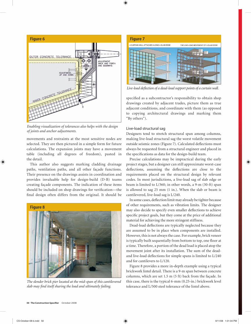
The tolerances are marked with envelopes outlining their extremes (Figure 6, page 50). These visual aids assist with conscientious façade creation, helping avoid unpleasant surprises in the fi eld and providing design of adjusting devices and movement joints. They also aid in communicating design intent to the team responsible for the fi nal design-built engineering and shop drawings. (In the majority of cases, engineering responsibility is placed on the contractor.)
Control joints and movements should be marked on all façade drawings. In collaboration with structural engineers, movement joints are identifi ed and coordinates of free
Figure 4
Spalling of a marble cladding caused by building movement.
Figure 5
Visualization of movement can be invaluable when it comes to designing joints and anchor adjustments.
1. Insulation2. Air Barrier3. Vapor Retarder
SystemThe in
1-877-336-4532 • Fax: (817) 633-2000E-mail: [email protected] • www.heatloksoy.com
In a single application, Demilec’s unique Heatlok™ Soy spray foam insulation creates a high-performance building envelope that offers long-term thermal resistance, an excellent air barrier, and a recognized vapor retarder in a wide variety of commercial and residential buildings. This highly-efficient, closed-cell, rigid polyurethane foam can only be applied by authorized contractors, trained and certified by Demilec USA as part of its ongoing commitment to environmental protection.
Demilec.indd 1 6/6/07 4:13:12 PM
CS-October-08-b.indd 49CS-October-08-b.indd 49 9/12/08 10:40:37 AM9/12/08 10:40:37 AM
50 The Construction Specifi er October 2008
movements and restraints at the most sensitive nodes are selected. They are then pictured in a simple form for future calculations. The expansion joints may have a movement table (including all degrees of freedom), pasted in the detail.
This author also suggests marking cladding drainage paths, ventilation paths, and all other façade functions. Their presence on the drawings assists in coordination and provides invaluable help for design-build (D-B) teams creating façade components. The indication of these items should be included on shop drawings for verifi cation—the fi nal design often differs from the original. It should be
specifi ed as a subcontractor’s responsibility to obtain shop drawings created by adjacent trades, picture them as true adjacent conditions, and coordinate with them (as opposed to copying architectural drawings and marking them “By others”).
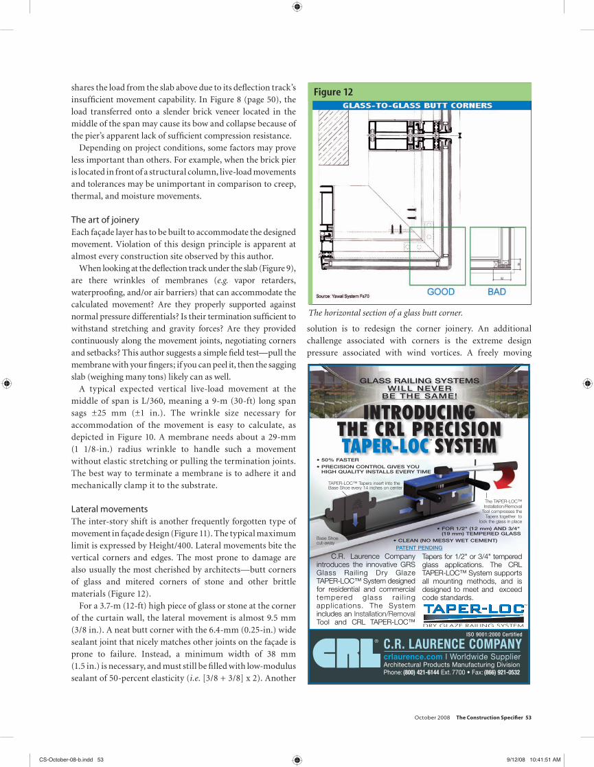
Live-load structural sagDesigners tend to stretch structural span among columns, making live-load structural sag the worst volatile movement outside seismic zones (Figure 7). Calculated defl ections must always be requested from a structural engineer and placed in the specifi cations as data for the design-build team.
Precise calculations may be impractical during the early project stages, but a designer can still approximate worst-case defl ections, assuming the defl ections are close to the requirements placed on the structural design by relevant codes. In most jurisdictions, a live-load sag of slab edge or beam is limited to L/360; in other words, a 9-m (30-ft) span is allowed to sag 25 mm (1 in.). When the slab or beam is cantilevered, live-load sag is L/240.
In some cases, defl ection limit may already be tighter because of other requirements, such as vibration limits. The designer may also decide to specify even smaller defl ections to achieve specifi c project goals, but they come at the price of additional material for achieving the more stringent stiffness.
Dead-load defl ections are typically neglected because they are assumed to be in place when components are installed. However, this is not always the case. For example, brick veneer is typically built sequentially from bottom to top, one fl oor at a time. Therefore, a portion of the dead load is placed atop the movement joint after its installation. The sum of the dead- and live-load defl ections for simple spans is limited to L/240 and for cantilevers to L/120.
Figure 8 provides a more in-depth example using a typical brickwork lintel detail. There is a 9-m span between concrete columns, which are set 1.5 m (5 ft) back from the façade. In this case, there is the typical 6-mm (0.25-in.) brickwork level tolerance and L/500 steel tolerance of the lintel above.
Figure 6
Enabling visualization of tolerances also helps with the design of joints and anchor adjustments.
Figure 7
Live-load defl ection of a dead-load support points of a curtain wall.
Figure 8
The slender brick pier located at the mid-span of this cantilevered slab may fi nd itself sharing the load and ultimately failing.
Dow.indd 1 9/5/08 3:24:45 PMCS-October-08-b.indd 50CS-October-08-b.indd 50 9/11/08 1:01:04 PM9/11/08 1:01:04 PM

52 The Construction Specifi er October 2008
The worst-case sum of tolerances of these two components may reach 13 mm (0.5 in.). The up/down adjustment of the lintel may help partially alleviate the discrepancy at the brick bed joint, but the joint would deviate from its theoretical line that may cause misalignment elsewhere on the façade.
At the middle of the reinforced concrete fl oor slab span, the maximum (i.e. code-allowed) vertical live-load movement is L/360, meaning the 9-m long span sags ±25 mm. The 1.5-m (5-ft) cantilever adds ±6 mm, making a total live-load defl ection of 32 mm (1.25 in.). In addition to this movement, partial dead-load defl ection is caused by subsequent installation of the brick veneer above, along with minor creep-, moisture-, and temperature-induced movements of these materials.1 The kiln-dried brick would gradually expand and press up against the creeping concrete (which, in turn, presses down).
However, the assembly illustrated in Figure 8 has a 9.5-mm (3/8-in.) ‘architectural’ bed joint fi lled with an elastic
material—a non-staining masonry sealant with maximum 25-percent movement capability that accommodates only a 2.3-mm (3/32-in.) movement. To handle the cumulative, worst-case movements and tolerances, the fi lled movement joint would need to be 140 mm (5.5 in.) high—more than one full brick course.
If a designer chose to limit the structural defl ection instead, the 2.3-mm movement limit would translate into an uneconomical ~L/5000 total defl ection limit. Such oversizing of the structure would not be recommended. There are many available design alternatives for high-movement interfaces. The obvious one would be either a stiff edge beam or a shingling joint, consisting of two overlapping components. However, both these hypothetical solutions affect the façade’s appearance.
The movement and tolerance (as in the described fl oor slab example) are often forgotten, causing brick veneer to share the live-load transfer from a slab. Similarly, the stud backup
Figure 9
Close-up of the joint at a defl ection track. Each façade layer must be built to accommodate the designed movement.
Figure 10
Design of a wrinkle to accommodate movement.
Figure 11
Story drift exemplifi es movement in façade design.
CS-October-08-b.indd 52CS-October-08-b.indd 52 9/12/08 10:41:24 AM9/12/08 10:41:24 AM
October 2008 The Construction Specifi er 53
shares the load from the slab above due to its defl ection track’s insuffi cient movement capability. In Figure 8 (page 50), the load transferred onto a slender brick veneer located in the middle of the span may cause its bow and collapse because of the pier’s apparent lack of suffi cient compression resistance.
Depending on project conditions, some factors may prove less important than others. For example, when the brick pier is located in front of a structural column, live-load movements and tolerances may be unimportant in comparison to creep, thermal, and moisture movements.
The art of joineryEach façade layer has to be built to accommodate the designed movement. Violation of this design principle is apparent at almost every construction site observed by this author.
When looking at the defl ection track under the slab (Figure 9), are there wrinkles of membranes (e.g. vapor retarders, waterproofi ng, and/or air barriers) that can accommodate the calculated movement? Are they properly supported against normal pressure differentials? Is their termination suffi cient to withstand stretching and gravity forces? Are they provided continuously along the movement joints, negotiating corners and setbacks? This author suggests a simple fi eld test—pull the membrane with your fi ngers; if you can peel it, then the sagging slab (weighing many tons) likely can as well.
A typical expected vertical live-load movement at the middle of span is L/360, meaning a 9-m (30-ft) long span sags ±25 mm (±1 in.). The wrinkle size necessary for accommodation of the movement is easy to calculate, as depicted in Figure 10. A membrane needs about a 29-mm (1 1/8-in.) radius wrinkle to handle such a movement without elastic stretching or pulling the termination joints. The best way to terminate a membrane is to adhere it and mechanically clamp it to the substrate.
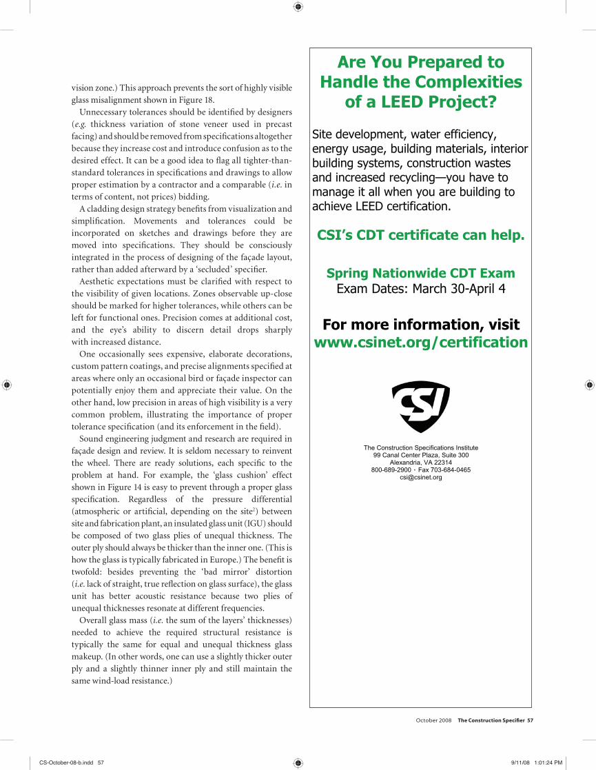
Lateral movementsThe inter-story shift is another frequently forgotten type of movement in façade design (Figure 11). The typical maximum limit is expressed by Height/400. Lateral movements bite the vertical corners and edges. The most prone to damage are also usually the most cherished by architects—butt corners of glass and mitered corners of stone and other brittle materials (Figure 12).
For a 3.7-m (12-ft) high piece of glass or stone at the corner of the curtain wall, the lateral movement is almost 9.5 mm (3/8 in.). A neat butt corner with the 6.4-mm (0.25-in.) wide sealant joint that nicely matches other joints on the façade is prone to failure. Instead, a minimum width of 38 mm (1.5 in.) is necessary, and must still be fi lled with low-modulus sealant of 50-percent elasticity (i.e. [3/8 + 3/8] x 2). Another
solution is to redesign the corner joinery. An additional challenge associated with corners is the extreme design pressure associated with wind vortices. A freely moving
® C.R. LAURENCE COMPANYcrlaurence.com I Worldwide SupplierArchitectural Products Manufacturing DivisionPhone: (800) 421-6144 Ext. 7700 • Fax: (866) 921-0532
ISO 9001:2000 Certified
GLASS RAILING SYSTEMSWILL NEVER
BE THE SAME!
TM
• CLEAN (NO MESSY WET CEMENT)
• 50% FASTER
• PRECISION CONTROL GIVES YOUHIGH QUALITY INSTALLS EVERY TIME
C.R. Laurence Companyintroduces the innovative GRSGlass Railing Dry GlazeTAPER-LOC™ System designedfor residential and commercialtempered g lass ra i l ing appl ications. The Systemincludes an Installation/RemovalTool and CRL TAPER-LOC™
Tapers for 1/2" or 3/4" temperedglass applications. The CRLTAPER-LOC™ System supportsall mounting methods, and isdesigned to meet and exceedcode standards.
• FOR 1/2" (12 mm) AND 3/4"(19 mm) TEMPERED GLASS
TAPER-LOC™ Tapers insert into the Base Shoe every 14 inches on center
The TAPER-LOC™Installation/Removal
Tool compresses theTapers together to
lock the glass in place
Base Shoecut-away
INTRODUCINGTHE CRL PRECISIONTAPER-LOC SYSTEM
PATENT PENDING
CRLaurence.indd 1 9/8/08 3:43:48 PM
Figure 12
The horizontal section of a glass butt corner.
CS-October-08-b.indd 53CS-October-08-b.indd 53 9/12/08 10:41:51 AM9/12/08 10:41:51 AM

54 The Construction Specifi er October 2008
corner butt joint is seldom properly supported against wind. A possible solution is a point-glass-fastening system.
The differential lateral movements (e.g. story drift, bending, and seismic movements) entail two kinds of movement within rectangular cladding panels: translation and rocking. A typical curtain wall employs both to ensure glass integrity. The panes’ movement is easy to imagine and calculate—Figure 13 has points of collisions marked by yellow stars.
Designers and contractors rarely take the wind-load bending movement into consideration. A lateral curtain wall defl ection, typically limited by code to L/175 or L/180 ratio, may cause undesired pounding or transfer of forces onto adjacent interior or exterior components. For example, an independently supported building component located in the
front of a 6-m (20-ft) high curtain wall that defl ects up to 35 mm (1 3/8 in.) horizontally in the middle of its height must be located far enough to prevent collision. In cases where distance is mandated by code (e.g. sprinkler heads), the support of components must be redesigned or the curtain wall should be made stiffer.
Figure 13
Cladding responds to story drift by rocking and swaying.
Figure 14
At left, distortions caused by interrelated temperature and pressure variations. At right, failure caused by thermal movement.
Figure 16
Plastic materials, such as polycarbonate, are characterized by large thermal movements and require careful detailing.
Figure 15
Expansion of 3-m (10-ft) length of material caused by 44 degrees C (80 degrees F).
CS-October-08-b.indd 54CS-October-08-b.indd 54 9/12/08 10:42:14 AM9/12/08 10:42:14 AM

October 2008 The Construction Specifi er 55
A rigidly mounted element installed close to the curtain wall may actually collide with the façade moving under a sudden gust. Newly popular cable walls are designed for very substantial lateral movements; they may defl ect several feet under the wind’s force. Such a defl ection may sound threatening, but it helps to remember the design provides for a wind gust statistically happening only once every 50 years. Many assemblies never see the full design load.
Thermal movementThermal movements are of lesser magnitude than the structural live-load defl ections, but are also important. A properly built outer cladding is insulated from the building interior. Its surface temperature may oscillate up to approximately Δt=100 C (Δt=200 F), depending on color, exposure, and other factors. Constrained components may exert pressures and move (Figure 14). Figure 15 shows a comparison of thermal movement for 3-m (10-ft) lengths of miscellaneous construction materials, caused by the 44-C (80-F) temperature differential.
Plastics are among the most volatile materials in terms of thermal movement—one of the reasons why acrylic glass or polycarbonate sheets are rarely installed in curtain wall profi les. A 6-m (20-ft) high piece of polycarbonate oscillates up to 35 mm (1 3/8 in.), and a plastic infi ll requires very deep glazing pockets to accommodate this movement. Needless to say, fastening it with screws is rarely a good idea. Figure 16 illustrates two sets of polycarbonate glass details.
With curtain wall façades that include dissimilar materials, one must accommodate movements between the cladding and the structure, along with those among the actual cladding components.
The Construction Specifications Institute 99 Canal Center Plaza, Suite 300
Alexandria, VA 22314 800-689-2900 Fax 703-236-4600
In the competitive world of construction, you have to prove yourself again and
again. There's no better way to demonstrate your superior abilities than
with CSI's CDT.
With CDT after your name, you'll belong to a select and highly respected group of construction professionals – architects, contractors, contract administrators,
specifiers, manufacturers’ representatives – known in the industry for their
comprehensive knowledge of the writing and management of
construction documents.
Spring Nationwide CDT Exam Exam Dates: March 30-April 4
www.csinet.org/certification
Credibility. Credentials.
CSI Designations.
““ The CDT is essential for anyone in our industry.
I interviewed with numerous leading architecture firms
around the country and always got a very positive response when they saw ’CSI, CDT’ at the end of
my name. It was one of the deciding factors for my current
company to hire me. “
- Rob Huserik, CSI, CDT
Cert_2V.indd 1 8/8/08 8:26:58 AM
CS-October-08-b.indd 55CS-October-08-b.indd 55 9/11/08 1:01:20 PM9/11/08 1:01:20 PM

56 The Construction Specifi er October 2008
Many sandwich materials (e.g. foam core panels) present the problem of thermal bowing. A 12-m (40-ft) long, 203-mm (6-in.) thick insulated core panel may bow outward over 51 mm (2 in.) in the center of its span, as a result of the 44-C temperature differential between its outer and inner layers (Figure 17). This bow happens regardless of its end restraint mode (i.e. regardless of degrees of freedom at its support anchors), as long as there is a composite action among layers.
Thermal movement is also an issue with mullions. A typical two-story aluminum mullion placed in an exterior environment can oscillate up to 13 mm (0.5 in.). This is why the majority of the framing profile’s mass should be located on the interior, conditioned side of assembly. A thermal bow may be induced by locating glass and thermal breaks in the middle of the assembly’s thickness, as seen in some storefront systems.
SolutionsDesigners must analyze building movements and tolerances, developing strategies for a desired, constructible, functional façade at optimal cost. Early development of cladding methods can help avoid connection failures, non-uniformities and irregularities of joints, jogs at intersections, and misalignment of faces. It also enables cost savings by determining the less important areas and types of tolerances that may be left lax or unspecifi ed.
A designer should specify the largest possible tolerance while maintaining proper functioning. In many cases, all that is needed is the specifi cation of a single tolerance and a fi t. An example is the specifi cation of permissible misalignment of joint width (as opposed to plumb and level relationship), and specifi ed line of initial alignment (e.g. edge or corner in a high-
Figure 18
The dimensional tolerance of glass produced the highly visible misalignment seen in the above photo.
Figure 17
In this example, the composite action of dissimilar materials brings about a thermal bow, regardless of its end restraint mode.
Featuring the patented Stofi x® curtainwall leveling system designed for building re-cladding, ideal for new construction. The system allows for addition of up to 6” of insulation and has a built-in rain screen. Façade materials include the patented Stonel ‘real’ brick panel, slate, metal panels, plaster or many additional façade materials being researched. One of the fastest curtainwall façades to install. Cuts time off of your construction schedule. The system can also be installed in severe weather conditions. The Stonel Systems is lightweight and Dry for a Lifetime.
Adjustable vertical track straightens old or new wall surfaces
2” to 6” insulation optional
Built-in 1” rain screen allows ventilation
No separate foundation or brick sill is required
Rain Screen Solutions Stonel Inc.
www.stonelsystems.com Toll free: (866) 487-0953
Corner returns optional
®
Stonel.indd 1 9/9/08 4:38:21 PM
CS-October-08-b.indd 56CS-October-08-b.indd 56 9/12/08 10:42:35 AM9/12/08 10:42:35 AM
October 2008 The Construction Specifi er 57
vision zone.) This approach prevents the sort of highly visible glass misalignment shown in Figure 18.
Unnecessary tolerances should be identifi ed by designers (e.g. thickness variation of stone veneer used in precast facing) and should be removed from specifi cations altogether because they increase cost and introduce confusion as to the desired effect. It can be a good idea to fl ag all tighter-than-standard tolerances in specifi cations and drawings to allow proper estimation by a contractor and a comparable (i.e. in terms of content, not prices) bidding.
A cladding design strategy benefi ts from visualization and simplifi cation. Movements and tolerances could be incorporated on sketches and drawings before they are moved into specifi cations. They should be consciously integrated in the process of designing of the façade layout, rather than added afterward by a ‘secluded’ specifi er.
Aesthetic expectations must be clarifi ed with respect to the visibility of given locations. Zones observable up-close should be marked for higher tolerances, while others can be left for functional ones. Precision comes at additional cost, and the eye’s ability to discern detail drops sharply with increased distance.
One occasionally sees expensive, elaborate decorations, custom pattern coatings, and precise alignments specifi ed at areas where only an occasional bird or façade inspector can potentially enjoy them and appreciate their value. On the other hand, low precision in areas of high visibility is a very common problem, illustrating the importance of proper tolerance specifi cation (and its enforcement in the fi eld).
Sound engineering judgment and research are required in façade design and review. It is seldom necessary to reinvent the wheel. There are ready solutions, each specifi c to the problem at hand. For example, the ‘glass cushion’ effect shown in Figure 14 is easy to prevent through a proper glass specifi cation. Regardless of the pressure differential (atmospheric or artifi cial, depending on the site2) between site and fabrication plant, an insulated glass unit (IGU) should be composed of two glass plies of unequal thickness. The outer ply should always be thicker than the inner one. (This is how the glass is typically fabricated in Europe.) The benefi t is twofold: besides preventing the ‘bad mirror’ distortion (i.e. lack of straight, true refl ection on glass surface), the glass unit has better acoustic resistance because two plies of unequal thicknesses resonate at different frequencies.
Overall glass mass (i.e. the sum of the layers’ thicknesses) needed to achieve the required structural resistance is typically the same for equal and unequal thickness glass makeup. (In other words, one can use a slightly thicker outer ply and a slightly thinner inner ply and still maintain the same wind-load resistance.)
Are You Prepared to Handle the Complexities
of a LEED Project?
Site development, water efficiency, energy usage, building materials, interior building systems, construction wastes and increased recycling—you have to manage it all when you are building to achieve LEED certification. CSI’s CDT certificate can help.
Spring Nationwide CDT Exam
Exam Dates: March 30-April 4
For more information, visit www.csinet.org/certification
The Construction Specifications Institute 99 Canal Center Plaza, Suite 300
Alexandria, VA 22314 800-689-2900 Fax 703-684-0465
Cert_2V.indd 1 8/8/08 8:25:01 AM
CS-October-08-b.indd 57CS-October-08-b.indd 57 9/11/08 1:01:24 PM9/11/08 1:01:24 PM

58 The Construction Specifi er October 2008
Additional Information
AuthorKarol Kazmierczak, CSI, CDT, AIA, ASHRAE, NCARB, LEED AP, is a senior building science architect at Morrison Hershfi eld Corp. The founding chair of the Miami Building Enclosure Council (BEC), he has more than
12 years of experience in building enclosure technical design, consulting, and inspection, with signifi cant knowledge of curtain walls and architectural glass and a particular focus on thermodynamics. He can be contacted via e-mail at [email protected].
AbstractAs many design professionals know, buildings move. However, curtain walls give buildings even more freedom to move. In fact, the biggest single difference between curtain walls and windows punched in the load-bearing
walls lies in the mechanisms that have to be implemented in the former to accommodate the movements between both a cladding and a structure, and among the cladding components themselves. This in-depth technical article examines what this means for designers.
MasterFormat No.08 44 00−Curtain Wall and Glazed Assemblies04 42 00–Exterior Stone Cladding
UniFormat No.B2010–Exterior Wall Exterior SkinB2020−Glazed Curtain Wall
Key WordsDivisions 04, 08Curtain wallsTolerances
CladdingsMovements
In many cases, a particular movement may eclipse all others (depending on the type of construction and its dependability on a particular solution or material). In this brief article,
several types of movement have been excluded (ranging from differential settlement and aero-elastic response to chemical changes and moisture), but this does not mean they are any less capable of causing catastrophic failure.
For example, aero-elastic response is a very signifi cant—and often forgotten—factor in high-rise tower design for zones with high wind speeds comparable to a small jet airplane.
ConclusionAs technology progresses and building enclosures are optimized for economy, these assemblies become less understood and more prone to failure. Proper design and specifi cation are in demand and a construction quality control should not be relied on to catch potential design errors.
In this author’s experience, movements and tolerances are least understood by designers who transition from small residential projects to large commercial and public facilities characterized by large spans and unique technologies. Understanding the nature of materials, their production limitations, and specifi cs of the project at hand is critical for delivery of constructible construction documents.
Notes1 See Technical Note 11C, Guide Specifi cations for Brick Masonry−Part IV, from the Brick Institute of America (BIA). See also the American Institute of Steel Construction’s (AISC’s) 303-05, Code of Standard Practice for Steel Buildings and Bridges.2 A glass manufactured at sea level under high air-conditioning pressure shrinks when transported to the mountains.
In designing curtain wall projects, the wheel is rarely required to be reinvented. As façades are refined over the years, a growing collection of ready solutions has become available to architects and engineers.
TempleInlsnd.indd 1 9/9/08 3:19:34 PMCS-October-08-b.indd 58CS-October-08-b.indd 58 9/11/08 1:02:34 PM9/11/08 1:02:34 PM