Movement Detector GJD 300 - buythis.co.uk · lighting controllers to give 24-hour visual and...
10
• A CCTV event trigger utilising two independent passive infrared detectors combined in a T05 package. Both sensors have to trigger before the detector signals an alarm. This high precision very reliable presence detector has been designed for use within CCTV installations. Programmable parameters include three normally open or normally closed configurations for the two CCTV volt free output relays, as well as a changeover timer, a pulse count feature and a choice of detection ranges from 8 to 30 metres. • In addition there are two switched negative outputs. The 'A' output gives a single 400ms trigger every time the detector activates and is generally used in conjunction with the GJD lighting controllers to give 24-hour visual and audible alarm indication. The 'S' output is a photocell-controlled signal giving a fixed 60-second trigger on activation. Additionally independent front and rear tamper circuits are combined to provide a volt free tamper alarm contact. The flexibility of the various outputs and timers allows the to be used in multiple situations without the need for any further customised equipment. • The integral dual axis tilt sensor allows 180° of pan and 90° tilt. This increases the speed of the outdoor installation and provides incredibly accurate aiming of the detection pattern. The electronics module is acrylic coated for additional component stability. It is encased in a vandal-resistant high impact zinc alloy housing with a UV stabilised translucent front cover ensuring the sensor is impervious to and unaffected by weather conditions. Additionally the combination of precision electronics, digital white light filter and double shielding eliminates false alarms from the sun and other visible light sources. The design gives a neat and professional appearance with no visible indication of the orientation of the detector head, and totally hides the wiring. 1 Installation & Set Up Guide Movement Detector GJD 300 Introduction
Transcript of Movement Detector GJD 300 - buythis.co.uk · lighting controllers to give 24-hour visual and...

• A CCTV event trigger utilising two independent passive infrared detectors combined in aT05 package. Both sensors have to trigger before the detector signals an alarm. This highprecision very reliable presence detector has been designed for use within CCTV installations.
Programmable parameters include three normally open or normally closed configurationsfor the two CCTV volt free output relays, as well as a changeover timer, a pulse count featureand a choice of detection ranges from 8 to 30 metres.• In addition there are two switched negative outputs. The 'A' output gives a single 400mstrigger every time the detector activates and is generally used in conjunction with the GJDlighting controllers to give 24-hour visual and audible alarm indication. The 'S' output is aphotocell-controlled signal giving a fixed 60-second trigger on activation.
Additionally independent front and rear tamper circuits are combined to provide a voltfree tamper alarm contact. The flexibility of the various outputs and timers allows the
to be used in multiple situations without the need for any further customisedequipment.• The integral dual axis tilt sensor allows 180° of pan and 90° tilt. This increases the speedof the outdoor installation and provides incredibly accurate aiming of the detection pattern.The electronics module is acrylic coated for additional component stability. It is encased ina vandal-resistant high impact zinc alloy housing with a UV stabilised translucent front coverensuring the sensor is impervious to and unaffected by weather conditions. Additionally thecombination of precision electronics, digital white light filter and double shielding eliminatesfalse alarms from the sun and other visible light sources.
The design gives a neat and professional appearance with no visibleindication of the orientation of the detector head, and totally hides the wiring.
1
Installation & Set Up Guide
Movement Detector GJD 300
Introduction

Template
fig. 1
Optional for Tamper Cup
fig. 3
fig. 2
Cable Holes
2
Installation & Set Up GuideStage 1 – Mounting the unit
- During installation the electronics must be protected against water, as trappedmoisture can effect or damage the unit.
1) Using the template provided drill the wall to accept the two fixing screws, thecable entry and the tamper cup (if used).See fig. 1 and 2.
Note: We recommened using the tamper cup on uneven wall surfaces.
2) Remove the cover assembly by loosening the locking screw using the allen keyprovided. The cover hinges from the top and lifts out of the location slot.See fig. 3.

3) Feed standard 12 core alarm cable into the cable entry; bare the wires andconnect to the removable terminal block as shown in fig. 7. Screw the unit to thewall ensuring that the tamper pin is correctly located and that the tamper microswitchis closed. See fig. 4 and 5. To aid installation, two spare tamper feet are provided.One is 1mm longer and the other is 2mm longer than the tamper foot originallyfitted. The tamper foot is a push fit and can be removed by carefully pulling it fromthe pin. See fig. 2.
4) Always ensure when replacing the electronics module that the LED is facingforward so as to ensure correct alignment of the beam pattern. (Refer sectiontitled "Multibeam Alignment & Masking")
5) When the detector has been aligned to suit the installation, replace the front coverand lock as shown.See fig. 6.
fig. 4
fig. 5fig. 6
3
Installation & Set Up GuideStage 1 – Mounting the unit

4
Installation & Set Up GuideStage 2 – Connecting the Unit
ALARM OUTPUT 1
TO GJD LIGHTING CONTROLLER
TO GJD LIGHTING CONTROLLER
MULTIPLEXER, PTZ DOME,DVR, ETC.
MULTIPLEXER, PTZ DOME,DVR, ETC.
NORMALLY CLOSEDTAMPER CIRCUIT FRONT + REAR
- A S +
12VDC SUPPLY
0V SUPPLY
ALARM OUTPUT 2
CC
TV2
CC
TV1
TAMPER CONNECTION
fig. 7
Stage 3 – Walk Test
fig. 7a
- The range of the detector increases without the front protective cover. Thereforethe front cover must be fitted to establish the correct beam pattern alignment andwhen testing the outputs. Use the programme table on page 7 to adjust the rangeas necessary and pan and tilt the lens module over the field of view to obtainthe correct coverage area.
- When the 'program' button is pressed momentarily the blue indicator lights andpulse count '1' is automatically selected. The unit can then be aligned. The blueindicator will light on the every time a detection takes place. Thistest mode will automatically cancel five minutes after last detection. Alternatively,remove the power and then re-apply.
- If automatic lighting is required to illuminate the area during recording, the connects directly into any of the GJD lighting controllers for
simultaneous recording and automatic lighting at dusk. The signals from thedetector also provide an audible and visual indication of detection activity 24 hoursa day. As the GJD lighting controllers also have a pulse count option, this mustbe set to '1' on the controller when using the for event recording.

fig. 9
fig. 8
1 23 4
5
Installation & Set Up GuideStage 4 – Multibeam Alignment & Masking
- When mounting higher than boundary fences rotate the module and mask off anybeams, either vertically or horizontally, that fall outside the area being covered.Use portions of the self-adhesive clear mask supplied to the rear, smooth side,of the lens as shown in the diagrams on the next page. Always replace the lensthe correct way up to ensure exact beam pattern coverage (the top of the Fresnellens is marked - TOP).See fig. 9.
- The GJD multifunction lens fitted to the detector produces 7 longrange beams and 7 medium to short range curtain beams. Movement across thebeams produces the best response and range, whilst movement towards thedetector will be less responsive. The unit detects the changes in heat and movementin the beam pattern, therefore items such as trees, shrubs, ponds, boiler flues andanimals should be considered when positioning the detector.
- The detector module is fitted with two sliding shutters to reduce the detection angle.An additional set of curtains is provided should the beam pattern need to benarrowed even further e.g. if the minimum detection angle of 10 degrees is required.The curtains are fitted to the pan and tilt module as indicated in fig. 8 below. Eachsection or the detector's lens gives a coverage pattern of approximately 10 degrees.See fig. 8.

MULTIBEAM - OPTIMUMHEIGHT: 3 METRESRANGE: MAXIMUMMODULE TILT: 0 DEGREE
MULTIBEAMHEIGHT: 6 METRESRANGE: MAXIMUMMODULE TILT: 9 DEGREE
PET IMMUNITYHEIGHT: 1.5 METRESRANGE: MAXIMUMMODULE TILT: -2 DEGREE
CURTAIN COVERAGEHEIGHT: 6 METRESRANGE: MAXIMUMMODULE TILT: 45 DEGREE
MASK THIS SECTION OFFFOR PET ALLEYAPPLICATIONS
UP TO 30 METRES
MASK THIS SECTION OFFFOR CURTAIN COVERAGE
APPLICATIONS
Beam Pattern set to maximum range- Masking top section of lens willreduce range to 20 metres
Beam Pattern set to minimum range.Masking top section of lens will reducerange to 6 metres
6
Installation & Set Up GuideStage 4 – Multibeam Alignment & Masking (Cont.)
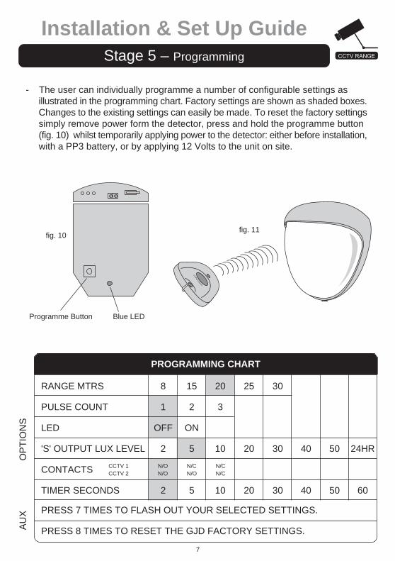
- The user can individually programme a number of configurable settings asillustrated in the programming chart. Factory settings are shown as shaded boxes.Changes to the existing settings can easily be made. To reset the factory settingssimply remove power form the detector, press and hold the programme button(fig. 10) whilst temporarily applying power to the detector: either before installation,with a PP3 battery, or by applying 12 Volts to the unit on site.
fig. 11
RANGE MTRS
PULSE COUNT
LED
'S' OUTPUT LUX LEVEL
CONTACTS
TIMER SECONDS
PROGRAMMING CHART
CCTV 1CCTV 2
8
1
OFF
2
2
15
2
ON
5
5
20
3
10
10
40
40
50
50
24HR
60
N/ON/O
N/CN/O
N/CN/C
PRESS 7 TIMES TO FLASH OUT YOUR SELECTED SETTINGS.
PRESS 8 TIMES TO RESET THE GJD FACTORY SETTINGS.
OP
TIO
NS
AU
X
25
20
20
30
30
30
7
Installation & Set Up GuideStage 5 – Programming
fig. 10
Blue LEDProgramme Button

To change any of the settings: -
1) Press the programme button as shown in fig. 10 (or key fob button shown infig. 11, 12) for the number of the Option to be changed i.e.once for range, twicefor pulse count, three times for LED, four times for Lux, five times for contacts& six times for timer.
2) Wait four seconds until the blue LED indicator goes off.
3) The indicator will then flash out the existing setting.
4) To change the setting for that option, press the button the number of timesrequired for the new setting.
5) The indicator blinks twice and the changes are stored.
Any alterations made to the settings are stored in the detector's nonvolatile memory.
EXAMPLE
To change the LED Setting from OFF to ON.
1) Press the programme button three times and release the button.
2) Wait until the indicator goes off.
3) The indicator will now flash once.
4) Press the programme button twice and release the button.
5) The indicator flashes twice showing that the option has been stored and thedetector returns to normal operation.
8
Installation & Set Up GuideStage 5 – Programming (Cont.)
NOTE: When power is applied to the the user has a time slot of 5 minutes to start using theIR keyfob. The timer can be reset by either pushing theprogram button as shown in fig.10 or by removingand then reapplying power to the
ON/OFF
fig. 12

9
Installation & Set Up GuideStage 6 – OPTION Definitions
PULSE COUNT- This is the number of times the unit has to detect on both of its sensors before
signalling an output.
LED MONITORLED Off - LED disabledLED On - LED signals a detection
LUX SETTING- This is the approximate level that the ambient light must reach before the 'S'
output will become active when there is an activation.
The 'S' output switches negative for 60 seconds when there is a detection andthe light level is below the programmed setting.
The 'S' output is an open collector type rated at a maximum of 25 mA.
CCTV1 & CCTV2 OUTPUTS- These are magnetically immune volt free relay contacts used to trigger alarm
inputs on connected equipment. They can be set to be both normally open, onenormally closed and one normally open or both normally closed.
TIMER- The timer setting adjusts the time that the relays change state after activation.
The contacts are rated at a maximum of 24V AC/DC @ 50 mA.
ACCESSORIES
GJD is able to supply the following accessories to aid installations:
GJD303 Infra Red key fob programmerGJD304 Conduit cable entry adaptor ringGJD305 Pole mount clamp

GJD Manufacturing LimitedUnit 2, Birch Industrial Estate, Whittle Lane, Heywood, OL10 2SX, UKTel: Sales +44 (0) 1706 363998 Technical: +44 (0) 1706 363990 Fax: +44 (0) 1706 363991E-mail: [email protected] Web: www.gjd.co.uk
GJD reserve the right to amend specifications without prior notice.
Detection Area
Coverage
Adjustment
Fresnel Lens
Customised Optics
Outputs
No.1
No.2
No.3
No.4
Power input
Current
Pulse Count
Temp. Compensation
Control
Walk Test
Operating Temp.
Housing
Protection Rating
Dimensions
Weight
Mounting Height
Cable < 200m
Cable < 500m
CE Mark
Programmable between 8 & 30 metres.
10-70 degrees detection angle, 30 m x 30 m coverage max.
180 degree pan + 90 degree tilt
Area reduction mask (if required).
28 zones for each Pyro pair, which can be masked with the curtain sliders
and special masking tape (supplied).
Double silicon shielded quad element eliminates 50,000 lux of white light
Silent solid state magnetically immune.
CCTV1
CCTV2
Output 'A'
Output 'S'
Volt free relay signal contact 24VAC/DC @ 50mA with
an integral 25R series resistor, selectable N/O & N/C.
Adjustable timer options: 2 to 60 seconds.
Volt free relay signal contact 24VAC/DC @ 50mA with
an integral 25R series resistor, selectable N/O & N/C.
Adjustable timer options: 2 to 60 seconds.
Open collector negative switching - 25mA max.
Alarm period 400ms.
Open collector negative switching - 25mA max.
Alarm period: detection + 60 seconds
Adjustable: Dusk (2 Lux) to 24 hour.
9 to 15 VDC.
9mA (12V nominal).
1 - 3.
Digital sensitivity adjustment.
Digital microprocessor - non volatile memory.
Output test mode with LED indication.
-20 to + 55 Centigrade
Conformally coated electronics for increased stability.
High impact zinc alloy.
IP 55.
145 x 120 x 115 mm.
750grams NET, 880grams GROSS.
Variable up to 6 metres - optimum height 3 metres.
Uitlising all five outputs (incl. tamper) - 12 core 7/0.2mm.
Utilising all five outputs (incl. tamper) - 12 core 16/0.2mm.
10
Technical Specification