Moustafa Beshir The University of Manchester...
39
Supervisor Prof. Yong Wang Moustafa Beshir The University of Manchester
Transcript of Moustafa Beshir The University of Manchester...
Supervisor Prof. Yong Wang
Moustafa Beshir
The University of Manchester

Problem Statement
There is a lack in the knowledge of the actual behaviour of
restraint composite beam when exposed to fire load
between failure and collapse which is needed to be
covered to avoid the progressive collapse of the building.
Progressive collapse could be a reduced if the robustness
of different structure components are considered such as
shear connector, connection and reinforcement detailing.
Because of the high cost of experimental work for fire test
especially if we want to represent the actual situation,
FEM could be used for fire resistance design.
2

Project Objectives:
The main objective of this research is to study the robustness
of composite framed structures considering the following
points:
Study the real behaviour of shear connector.
Study the behaviour or restrained composite beam at
ambient and elevated temperature considering the actual
shear connector behaviour and the end conditions.
3
Behaviour of Shear Connector
Shear connector is a structural element used to achieve a
composite action between the steel beam and concrete slab.
These connectors are designed mainly to transmit
longitudinal shear along the interface and to be able to resist
uplifting forces caused by the tendency for the slab to
separate from the beam.
4

Push-out test for the shear connector
5
Standard Push-out test
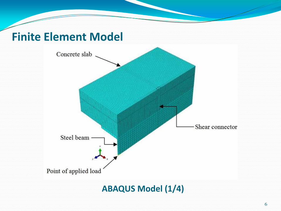
Finite Element Model
6
ABAQUS Model (1/4)

Boundary Conditions
7

Interaction and Constrains
8
Constrain between steel beam and the shear
connectors
Interaction between concrete slab and the
shear connector
Interaction between concrete slab and the steel
beam

Loading
9
Reference node where the load is applied
Reference node connected to the steel beam flange and web by coupling

Specimens labels and studied parameters No. Concrete
Grade Analysis technique Notes
Load Control Static
Dis. Control
General RIKS General
Sp1
C50
√ - - Solid Slab
Sp2 - √ -
Sp3 - - √
Sp4 C35 - - √
Spp1 C35 - - √ Profiled slab
10

Validation of Sp1
11
0
20
40
60
80
100
120
140
0 2 4 6 8 10 12 14
Load
/Stu
d K
N
Slip mm
Finite element
Experimental
Sp1
C50 – Load control –Static General

Comparison between different loading techniques
12
0
20
40
60
80
100
120
140
0 2 4 6 8 10 12 14 16 18
Loa
d /
Stu
d K
N
Slip mm
Load Control- Static General Sp1
Load Control Static RIKS Sp2
Displacement Control Sp3
Sp4
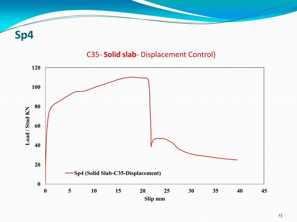
13
C35- Solid slab- Displacement Control)
0
20
40
60
80
100
120
0 5 10 15 20 25 30 35 40 45
Lo
ad
/ S
tud
KN
Slip mm
Sp4 (Solid Slab-C35-Displacement)

Spp1
14
C35- Profiled Slab- Displacement Control)
0
20
40
60
80
100
120
0 2 4 6 8 10 12 14 16 18 20 22 24 26 28
Lo
ad
/Stu
d K
N
Slip mm
Spp1-Profiled Slab-Displacement)
Point 1 ( shear stud starts to yielded)
Point 2 ( shear stud fully yielded)
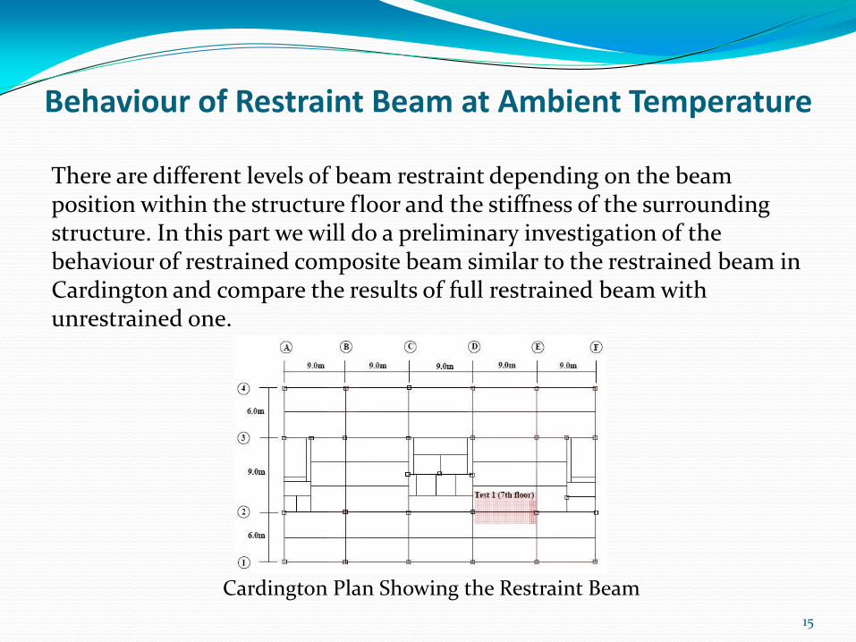
Behaviour of Restraint Beam at Ambient Temperature
There are different levels of beam restraint depending on the beam position within the structure floor and the stiffness of the surrounding structure. In this part we will do a preliminary investigation of the behaviour of restrained composite beam similar to the restrained beam in Cardington and compare the results of full restrained beam with unrestrained one.
15
Cardington Plan Showing the Restraint Beam
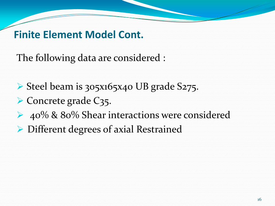
Finite Element Model Cont.
The following data are considered :
Steel beam is 305x165x40 UB grade S275.
Concrete grade C35.
40% & 80% Shear interactions were considered
Different degrees of axial Restrained
16

Geometry of the model
17
Finite Element Model of Composite beam)

Parametric Study
18
No. Degree of shear interaction % Axial restraint
U-40-Amb
40%
0
2-R-40-Amb 2
5-R-40-Amb 5
10-R-40-Amb 10
15-R-40-Amb 15
20-R-40-Amb 20
30-R-40-Amb 30
100-R-40-Amb 100
R-40-Amb Full
U-80-Amb 80%
0
R-80-Amb Full

Effect of % of Axial Restrain on Catenary Action Force (N/Nf=40%)
19
0
100
200
300
400
500
600
700
800
900
1000
1100
1200
0 5 10 15 20 25 30 35 40 45 50 55 60 65 70 75 80 85 90 95 100 105
Ca
ten
art
Act
ion
Fo
rce
KN
% Axial restraint
Catenary Action Force N/Nf=40%

Effect of % of Axial Restrain on Shear Connector (N/Nf=40%)
20
0
200
400
600
800
1000
1200
0 5 10 15 20 25
Lo
ad
W.L
KN
Shear Connector Slip
Full Rest
100%
30%
20%
15%
10%
5%
2%
0%

Effect of % of Axial Restrain on Beam Deflection (N/Nf=40%)
21
-1200
-1000
-800
-600
-400
-200
0
0 5 10 15 20 25 30 35 40 45 50 55 60 65 70 75 80 85 90 95 100 105
Def
lect
ion
mm
% Axial Restraint
Beam Deflection N/Nf=40%
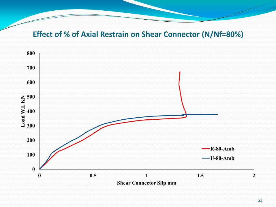
Effect of % of Axial Restrain on Shear Connector (N/Nf=80%)
22
0
100
200
300
400
500
600
700
800
0 0.5 1 1.5 2
Lo
ad
W.L
KN
Shear Connector Slip mm
R-80-Amb
U-80-Amb
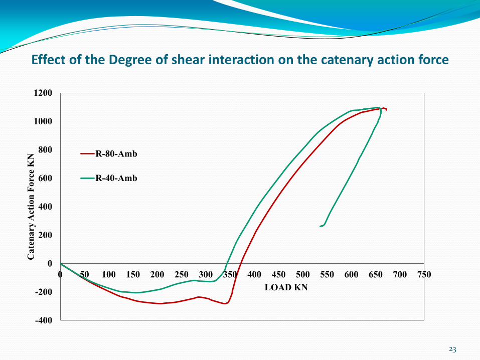
Effect of the Degree of shear interaction on the catenary action force
23
-400
-200
0
200
400
600
800
1000
1200
0 50 100 150 200 250 300 350 400 450 500 550 600 650 700 750
Ca
ten
ary
Act
ion
Fo
rce
KN
LOAD KN
R-80-Amb
R-40-Amb

Behaviour of Restraint Beam at Elevated Temperature
24

Parametric Study
25
No. Degree of shear interaction
Load Ratio %
% Axial restraint
U-40-FR-30
40%
30 0
R-40-FR-30 30 Full
U-40-FR-70
70
0
2%R-40-FR-70 2
15%R-40-FR-70 15
R-40-FR-70 Full
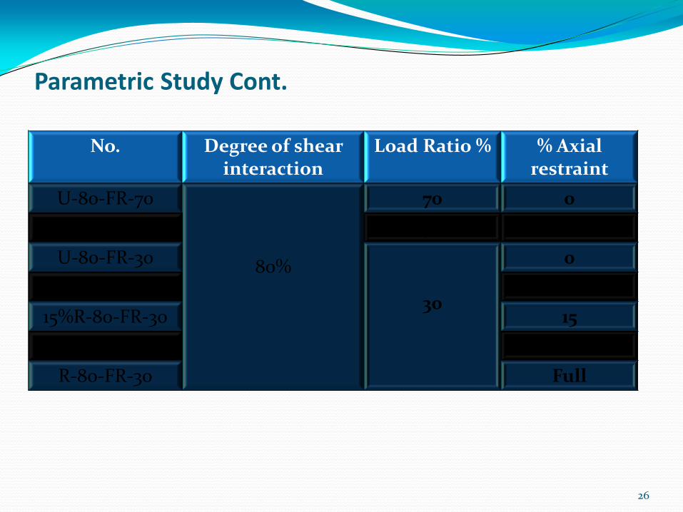
Parametric Study Cont.
26
No. Degree of shear interaction
Load Ratio %
% Axial restraint
U-80-FR-70
80%
70 0
R-80-FR-70 70 Full
U-80-FR-30
30
0
2%R-80-FR-30 2
15%R-80-FR-30 15
100%R-80-FR-30 100
R-80-FR-30 Full
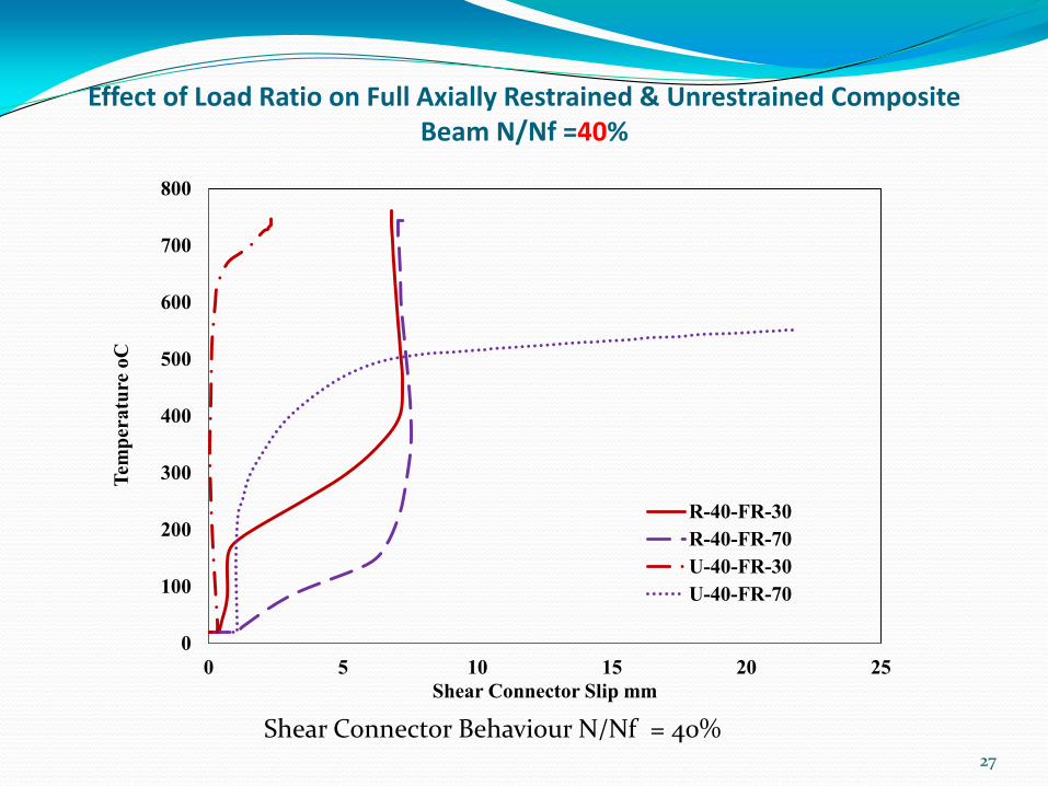
27
0
100
200
300
400
500
600
700
800
0 5 10 15 20 25
Tem
per
atu
re o
C
Shear Connector Slip mm
R-40-FR-30
R-40-FR-70
U-40-FR-30
U-40-FR-70
Shear Connector Behaviour N/Nf = 40%
Effect of Load Ratio on Full Axially Restrained & Unrestrained Composite Beam N/Nf =40%

Effect of Load Ratio on Full Axially Restrained & Unrestrained Composite Beam N/Nf =80%
28
Shear Connector Behaviour N/Nf = 80%
0
100
200
300
400
500
600
700
800
-0.1 0 0.1 0.2 0.3 0.4 0.5 0.6 0.7 0.8
Tem
per
atu
re o
C
Shear Connector Slip mm
R-80-FR-30
R-80-FR-70
U-80-FR-30
U-80-FR-70

Effect of Load Ratio & Degrees of Shear Interaction on Full Axially Restrained Beam
29
-1000
-900
-800
-700
-600
-500
-400
-300
-200
-100
0
0 100 200 300 400 500 600 700 800
Def
lect
ion
mm
Temperature oC
R-80-FR-30
R-40-FR-30
R-80-FR-70
R-40-FR-70

Effect of Load Ratio & Degrees of Shear Interaction on Full Axially Restrained Beam
30
-1200
-1000
-800
-600
-400
-200
0
200
400
600
0 100 200 300 400 500 600 700 800
Ax
ial
Rea
ctio
n K
N Temperature oC
R-80-FR-30
R-40-FR-30
R-80-FR-70
R-40-FR-70
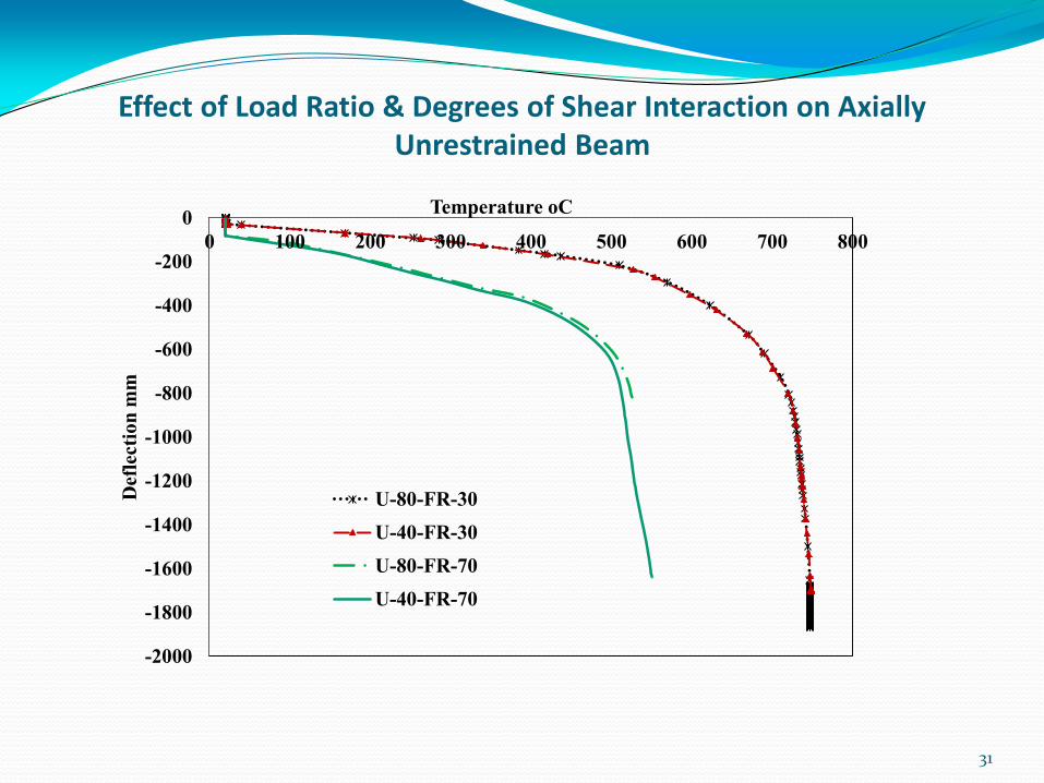
Effect of Load Ratio & Degrees of Shear Interaction on Axially Unrestrained Beam
31
-2000
-1800
-1600
-1400
-1200
-1000
-800
-600
-400
-200
0
0 100 200 300 400 500 600 700 800
Def
lect
ion
mm
Temperature oC
U-80-FR-30
U-40-FR-30
U-80-FR-70
U-40-FR-70
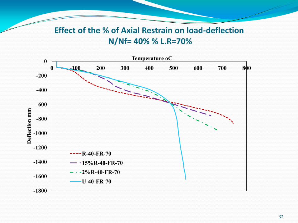
Effect of the % of Axial Restrain on load-deflection N/Nf= 40% % L.R=70%
32
-1800
-1600
-1400
-1200
-1000
-800
-600
-400
-200
0
0 100 200 300 400 500 600 700 800
Def
lect
ion
mm
Temperature oC
R-40-FR-70
15%R-40-FR-70
2%R-40-FR-70
U-40-FR-70

Effect of the % of Axial Restrain on the Catenary action Force N/Nf= 40% % L.R=70%
33
-600
-500
-400
-300
-200
-100
0
100
200
300
400
500
0 100 200 300 400 500 600 700 800
Ax
ial
Rea
ctio
n K
N
Temperature oC
R-40-FR-70
15%R-40-FR-70
2%R-40-FR-70
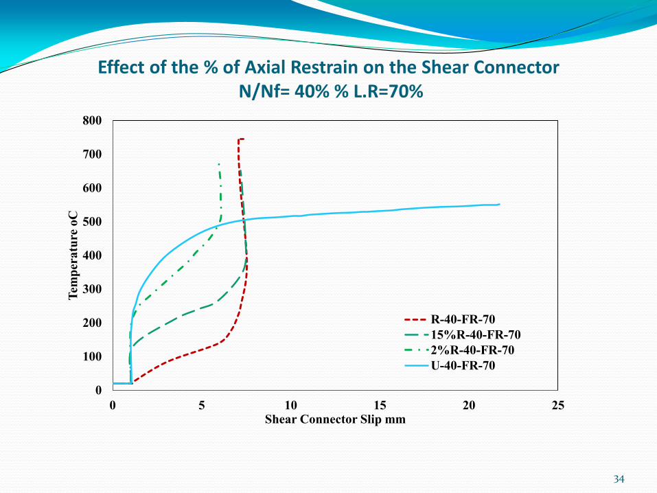
Effect of the % of Axial Restrain on the Shear Connector N/Nf= 40% % L.R=70%
34
0
100
200
300
400
500
600
700
800
0 5 10 15 20 25
Tem
per
atu
re o
C
Shear Connector Slip mm
R-40-FR-70
15%R-40-FR-70
2%R-40-FR-70
U-40-FR-70
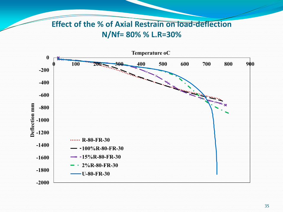
Effect of the % of Axial Restrain on load-deflection N/Nf= 80% % L.R=30%
35
-2000
-1800
-1600
-1400
-1200
-1000
-800
-600
-400
-200
0
0 100 200 300 400 500 600 700 800 900
Def
lect
ion
mm
Temperature oC
R-80-FR-30
100%R-80-FR-30
15%R-80-FR-30
2%R-80-FR-30
U-80-FR-30

Effect of the % of Axial Restrain on the Catenary action Force N/Nf= 80% % L.R=30%
36
-1200
-1000
-800
-600
-400
-200
0
200
0 100 200 300 400 500 600 700 800 900
Ax
ial
Rea
ctio
n K
N
Temperature oC
R-80-FR-30
100%R-80-FR-30
15%R-80-FR-30
2%R-80-FR-30
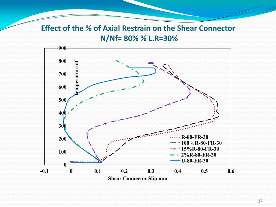
Effect of the % of Axial Restrain on the Shear Connector N/Nf= 80% % L.R=30%
37
0
100
200
300
400
500
600
700
800
900
-0.1 0 0.1 0.2 0.3 0.4 0.5 0.6
Tem
per
atu
re o
C
Shear Connector Slip mm
R-80-FR-30100%R-80-FR-3015%R-80-FR-302%R-80-FR-30U-80-FR-30

Conclusion
The results of displacement control gave gives more
realistic behaviour of the shear connector .
In the ambient temperature, the degree of shear
interaction has a major effect on the shear connector in the
unrestrained beam while the effect is limited when
providing an axial restrain.
At elevated temperature, the load ratio has a major effect
on the behaviour of the shear connector in unrestrained
while the effect is limited when providing axial restrain.
38

Thanks
39