
Mounting instructions for electronic locks SELO
4
Date: 08.08 Subject to technical modifications Elektronikschloesser-Montageanleitung-Version SELO-08.08-englisch.p65 Mounting instructions for electronic locks SELO 1. Adjusting the size of the lock spindle The purpose of lock spindle (6) is to mechanically connect data input unit (10) and electromechanical lock module (1). If the exact length of the lock spindle was not indicated in the purchase order, the spindle has to be cut to the right length and a new pin hole drilled before mounting. Our “Tool for drilling and shortening SELO electronic lock spindles” (Article no. 900 301) is designed to simplify these operations.. As an alternative, the cutting-to-size and drilling of the spindle can also be executed according to the instructions in the diagram pro- vided. Begin by measuring wall thickness T of the safe door; this is the distance between the mounting surfaces of data input unit and interior lock module, and add 32 mm. Shorten the lock spindle to this total length from the rounded end. Next, drill a new hole for the pin, diameter between 3.05 and 3.10 mm, at a 3 mm distance from the end of the spindle, making sure that the hole axis is at a 90° angle to the key areas of the lock spindle. To make the following steps of the mounting procedure easier, debur or lightly chamfer the pin hole. N.B.: Any distance in excess of the recommended 3 mm will cause problems at a later stage of the mounting procedure. Mounting sequence: 1. Adjusting the size of the lock spindle 2. Connecting lock spindle and input unit 3. Mounting the complete input unit on the outside of a safe door 4. Mounting the electromechanical lock module inside a safe door 5. Making the electrical connection between input unit and lock module electronics 2. Connecting lock spindle and input unit Connect lock spindle (6) and data input unit (10) using the locking pin (12) (ø3 mm) provided, and secure it with flat securing piece (14). The diagram below shows the input unit in “closed”-position; it is vertical and the keypad inscrip- tions can be read normally. If the input unit is held in one hand, the rear bottom plate (11) can be turned back and forth 180° between two limit stops. T + 32 T 3 ø3,05...ø3,1 9,3 (22,7) 1 6 10 -- page 1 -- 10 13 11 15
Transcript of Mounting instructions for electronic locks SELO
Date: 08.08Subject to technical modifications Elektronikschloesser-Montageanleitung-Version SELO-08.08-englisch.p65
Mounting instructionsfor electronic locks
SELO
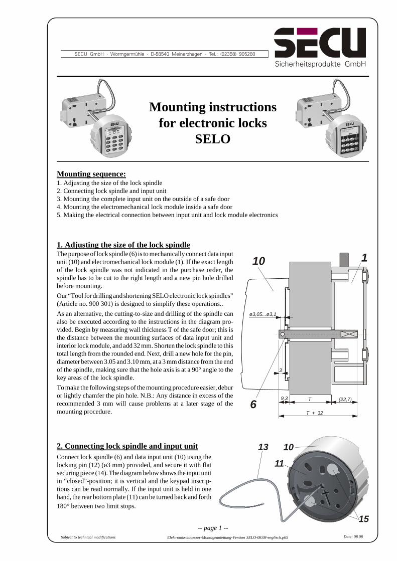
1. Adjusting the size of the lock spindleThe purpose of lock spindle (6) is to mechanically connect data inputunit (10) and electromechanical lock module (1). If the exact lengthof the lock spindle was not indicated in the purchase order, thespindle has to be cut to the right length and a new pin hole drilledbefore mounting.Our “Tool for drilling and shortening SELO electronic lock spindles”(Article no. 900 301) is designed to simplify these operations..As an alternative, the cutting-to-size and drilling of the spindle canalso be executed according to the instructions in the diagram pro-vided. Begin by measuring wall thickness T of the safe door; this isthe distance between the mounting surfaces of data input unit andinterior lock module, and add 32 mm. Shorten the lock spindle to thistotal length from the rounded end. Next, drill a new hole for the pin,diameter between 3.05 and 3.10 mm, at a 3 mm distance from the endof the spindle, making sure that the hole axis is at a 90° angle to thekey areas of the lock spindle.To make the following steps of the mounting procedure easier, deburor lightly chamfer the pin hole. N.B.: Any distance in excess of therecommended 3 mm will cause problems at a later stage of themounting procedure.
Mounting sequence:1. Adjusting the size of the lock spindle2. Connecting lock spindle and input unit3. Mounting the complete input unit on the outside of a safe door4. Mounting the electromechanical lock module inside a safe door5. Making the electrical connection between input unit and lock module electronics
2. Connecting lock spindle and input unitConnect lock spindle (6) and data input unit (10) using thelocking pin (12) (ø3 mm) provided, and secure it with flatsecuring piece (14). The diagram below shows the input unitin “closed”-position; it is vertical and the keypad inscrip-tions can be read normally. If the input unit is held in onehand, the rear bottom plate (11) can be turned back and forth180° between two limit stops.
T + 32
T
3
ø3,05...ø3,1
9,3 (22,7)
1
6
10
-- page 1 --
1013
11
15
16
16
1412
6
14
12
6
9
9611
17
13-- page 2 --
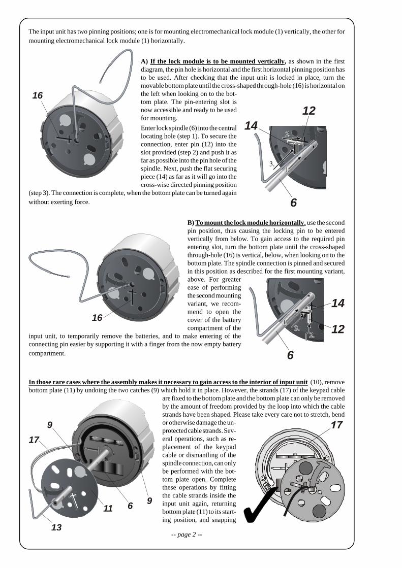
The input unit has two pinning positions; one is for mounting electromechanical lock module (1) vertically, the other formounting electromechanical lock module (1) horizontally.
A) If the lock module is to be mounted vertically, as shown in the firstdiagram, the pin hole is horizontal and the first horizontal pinning position hasto be used. After checking that the input unit is locked in place, turn themovable bottom plate until the cross-shaped through-hole (16) is horizontal onthe left when looking on to the bot-tom plate. The pin-entering slot isnow accessible and ready to be usedfor mounting.Enter lock spindle (6) into the centrallocating hole (step 1). To secure theconnection, enter pin (12) into theslot provided (step 2) and push it asfar as possible into the pin hole of thespindle. Next, push the flat securingpiece (14) as far as it will go into thecross-wise directed pinning position
(step 3). The connection is complete, when the bottom plate can be turned againwithout exerting force.
B) To mount the lock module horizontally, use the secondpin position, thus causing the locking pin to be enteredvertically from below. To gain access to the required pinentering slot, turn the bottom plate until the cross-shapedthrough-hole (16) is vertical, below, when looking on to thebottom plate. The spindle connection is pinned and securedin this position as described for the first mounting variant,above. For greaterease of performingthe second mountingvariant, we recom-mend to open thecover of the batterycompartment of the
input unit, to temporarily remove the batteries, and to make entering of theconnecting pin easier by supporting it with a finger from the now empty batterycompartment.
In those rare cases where the assembly makes it necessary to gain access to the interior of input unit (10), removebottom plate (11) by undoing the two catches (9) which hold it in place. However, the strands (17) of the keypad cable
are fixed to the bottom plate and the bottom plate can only be removedby the amount of freedom provided by the loop into which the cablestrands have been shaped. Please take every care not to stretch, bendor otherwise damage the un-protected cable strands. Sev-eral operations, such as re-placement of the keypadcable or dismantling of thespindle connection, can onlybe performed with the bot-tom plate open. Completethese operations by fittingthe cable strands inside theinput unit again, returningbottom plate (11) to its start-ing position, and snapping

3. Mounting the complete input unit on the outsideof a safe doorThe input unit is positioned from the outside on to the level frontsurface of the safe door. To do this, screw the two metric M4screws included in the supply as far as possible into any twoopposite threaded holes of the total of six M4 holes. The screwheads only serve to fix the input unit in its position on the safedoor. As an alternative, the input unit can also be secured with twopan head screws (head diameter 8 mm or 0.31“) with an inchthread #8-32. The maximum permissible through-hole throughthe door for the lock spindle and the cable gland is indicated in themounting diagram. It can be in any direction, but please note thatthe indicated contour must not be exceeded. To protect cable (13),check that the inside and outside edges of the through-hole haveno sharp edges and no burrs.Input unit (10) can now be placed into the through-hole togetherwith spindle (6) and cable (13). It is held in place by plugging itonto the two screw heads provided this purpose.The keypad cable runs in parallel to the shaft. Check that the cable is not twisted several times beside the spindle. Thetwo adhesive points (15) may be used as a mounting aid. To use them, remove the protective cling film. After pluggingthe input unit into place, the two adhesive points (15) will hold the input unit long enough for the subsequent mountingof the lock module on the inside of the safe door to be completed.
17 17
4. Mounting of the electromechanical lock moduleinside a safe doorAlthough the lock module (1) can be mounted in any direction, it isimportant to pay attention to the orientation of the axes of lockmodule and input panel: the maximum lateral angular deviation ofthe drive shaft must not exceed 2°. The lock module must beprotected against direct or indirect access from the outside byproviding suitable armoring. On locks from lock class 2(B), therehave to be at least layers of steel at a distance from each other witha minimum thickness of 3 mm each between the lock module and theouter surface of the safe door. When mounting is in progress, avoidgetting humidity, dust or dirt into the lock module. Do not oil, greaseor paint the electromechanical lock module. Please note that for thelock module to work perfectly, the humidity of the ambient air (non-condensing) should not exceed 95%. This means that any concretefloor adjoining the room where the bolt work is location must havedried.
Date: 08.08Elektronikschloesser-Montageanleitung-Version SELO-08.08-englisch.p65
131
347
-- page 3 --
the bottom plate back in place. This completes preparing the input unit for mounting. When fitting the bottom plate, makeabsolutely sure not to pinch or otherwise damage the strands of the keyboard cable. Even minor damage to the strandsduring assembly may eventually cause the cable to break.
Subject to technical modifications
Lock spindle andcable entry (anydirection, but donot exceed maximumdimensions)
Outline of input unit20,7
28
20,7
20,7
20,7
9
ø11,
2
27,5
30
45°
M4(or, as analternative,inch thread #8-32)
M4
M4
M4
M4
M4
5. Making the electrical connection between input unit and lock module electronicsEnter the keypad cable (13) - tension-free and making sure it is not subjected to any strain – into the lead-in hole for thelock spindle. The lock module has been provided with a semi-rounded slot to allow the in-bound keypad cable to be laiddirectly underneath the lock module without denting it as an alternative mounting method.Enter the cable up to the plug area of the lock module andconnect the cable. If the cable is too long, shape it into aloop using cable binders or adhesive tape. Make absolutelysure the cable does not touch any of the moving elementsof the door mechanism. If the lock being installed is one ofour all-redundant designs, it will have two separate plug-type connections, right next to each other, instead of one.Assigning the cable plugs to the bushings of the two printedcircuit boards is of no relevance when the lock is mountedfor the first time. Just make sure the connection is tension-free. Mounting complete, check the lock for proper functioningseveral times with the safe door open.
6. Key bolt resistance to VdS 2396When used normally, the maximum permissible tensile and compression forces exertedon the key bolt are 5N.The illustration shows under which maximum forces applied to the key bolt (in thedirection of opening as well as at 90° angles from lateral directions) the lock will still retainsome of its locking capability (resistance against forceful attack).
5
5
62
14
74 8
13
-- page 4 --
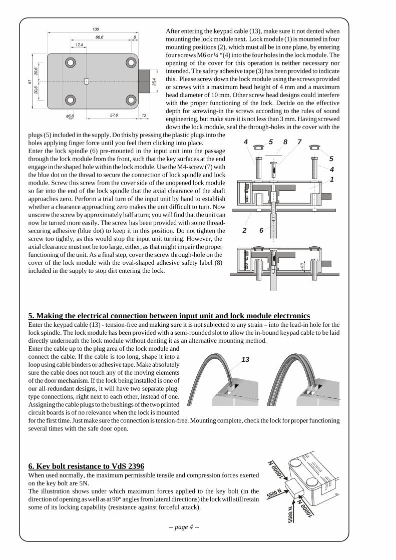
After entering the keypad cable (13), make sure it not dented whenmounting the lock module next. Lock module (1) is mounted in fourmounting positions (2), which must all be in one plane, by enteringfour screws M6 or ¼ “(4) into the four holes in the lock module. Theopening of the cover for this operation is neither necessary norintended. The safety adhesive tape (3) has been provided to indicatethis. Please screw down the lock module using the screws providedor screws with a maximum head height of 4 mm and a maximumhead diameter of 10 mm. Other screw head designs could interferewith the proper functioning of the lock. Decide on the effectivedepth for screwing-in the screws according to the rules of soundengineering, but make sure it is not less than 3 mm. Having screweddown the lock module, seal the through-holes in the cover with the
plugs (5) included in the supply. Do this by pressing the plastic plugs into theholes applying finger force until you feel them clicking into place.Enter the lock spindle (6) pre-mounted in the input unit into the passagethrough the lock module from the front, such that the key surfaces at the endengage in the shaped hole within the lock module. Use the M4-screw (7) withthe blue dot on the thread to secure the connection of lock spindle and lockmodule. Screw this screw from the cover side of the unopened lock moduleso far into the end of the lock spindle that the axial clearance of the shaftapproaches zero. Perform a trial turn of the input unit by hand to establishwhether a clearance approaching zero makes the unit difficult to turn. Nowunscrew the screw by approximately half a turn; you will find that the unit cannow be turned more easily. The screw has been provided with some thread-securing adhesive (blue dot) to keep it in this position. Do not tighten thescrew too tightly, as this would stop the input unit turning. However, theaxial clearance must not be too large, either, as that might impair the properfunctioning of the unit. As a final step, cover the screw through-hole on thecover of the lock module with the oval-shaped adhesive safety label (8)included in the supply to stop dirt entering the lock.