MOUNTING BRACKET KIT KIT# 521877-1 INSTALLATION INSTRUCTIONS I N C
6
KIT# 521877-1 12/6/17 KS ROADMASTER, Inc. 6110 NE 127th Ave. Vancouver, WA 98682 360-896-0407 fax 360-735-9300 www.roadmasterinc.com BASEPLATE KIT INSTALLATION INSTRUCTIONS FAILURE TO FOLLOW THESE INSTRUCTIONS CAN RESULT IN DEATH, PERSONAL INJURY OR PROPERTY DAMAGE R O A D M A S T E R , I N C. ITEM QTY NAME MATERIAL 1........... 4 ......... 3/8” x 1 1/4” BOLT...................................................... 350060-00 2........... 4 ......... 3/8” LOCK WASHER ................................................. 350305-00 3........... 4 ......... 3/8” FLAT WASHER .................................................. 350304-00 4........... 4 ......... 3/8” HEX NUT ............................................................ 350254-00 5........... 2 ......... QUICK LINK .............................................................. 200008-00 6........... 2 ......... 8” SAFETY CABLE .................................................... 500646-08 7........... 1 ......... MAIN RECEIVER ...................................................... C-001569 8........... 1 ......... DRIVER SIDE ARM ................................................... C-001570 9........... 1 ......... PASSENGER SIDE ARM .......................................... C-001571 10......... 5 ......... ZIP TIE ....................................................................... 300140-10 1 2 3 5 6 7 8 9 4
Transcript of MOUNTING BRACKET KIT KIT# 521877-1 INSTALLATION INSTRUCTIONS I N C

KIT# 521877-112/6/17
KS
ROADMASTER, Inc. 6110 NE 127th Ave. Vancouver, WA 98682 360-896-0407 fax 360-735-9300 www.roadmasterinc.com
BASEPLATE KIT INSTALLATION INSTRUCTIONS
FAILURE TO FOLLOW THESE INSTRUCTIONS CAN RESULT IN DEATH, PERSONAL INJURY OR PROPERTY DAMAGE
R
O
A
D
M
A
S
T
E
R,
I
N
C.
ITEM QTY NAME MATERIAL1...........4 ......... 3/8” x 1 1/4” BOLT ......................................................350060-002...........4 ......... 3/8” LOCK WASHER .................................................350305-003...........4 ......... 3/8” FLAT WASHER ..................................................350304-004...........4 ......... 3/8” HEX NUT ............................................................350254-005...........2 ......... QUICK LINK ..............................................................200008-006...........2 ......... 8” SAFETY CABLE ....................................................500646-087...........1 ......... MAIN RECEIVER ......................................................C-0015698...........1 ......... DRIVER SIDE ARM ...................................................C-0015709...........1 ......... PASSENGER SIDE ARM ..........................................C-00157110.........5 ......... ZIP TIE .......................................................................300140-10
1
2
3
5
6
7
8
94

KIT# 521877-112/6/17
KS
BASEPLATE KIT INSTALLATION INSTRUCTIONS
ROADMASTER, Inc. 6110 NE 127th Ave. Vancouver, WA 98682 360-896-0407 fax 360-735-9300 www.roadmasterinc.com
IMPORTANT: All baseplates must be assembled with all the bolts left loose for final adjustment and positioning (before tightening) unless otherwise instructed. All bolts must be torqued for proper strength. If more than one bolt is used per fastening point, the diagram may only show one.
• Use flat washers over all slotted holes • Use lock washers on all fasteners
• Installation of most baseplates requires moderate mechanical ap-titude and skills. We strongly recommend professional installation by an experienced installer.
• The installer must read the instructions and use all bolts and parts supplied. Failure to do so could result in loss of the towed vehicle.
• Use Loctite® Red on all bolts used for mounting this bracket.
• Every 3,000 miles, the owner must inspect the fasteners for proper torque, according to the bolt torque requirements chart on the last page of these instructions. The owner must also inspect all mount-ing points for cracks or other signs of fatigue every 3,000 miles. Failure to do so could result in loss of the towed vehicle.
• The owner must check the vehicle manufacturer's instructions for the proper procedure(s) to prepare the vehicle for towing. Some vehicles must be equipped with a transmission lube pump, an axle disconnect, driveline disconnect or free-wheeling hubs before they can be towed. Failure to properly equip the vehicle will cause severe damage to the transmission.
• If running changes were made by the vehicle manufacturer after this kit was designed, some bolts or other fasteners in the hardware pack may no longer be the correct size. It is the installer’s responsibility to verify that the baseplate is securely fastened to the vehicle and fit-ted with the correct hardware to account for these changes. Failure to securely fasten the baseplate could result in loss of the towed vehicle.
• If the towed vehicle has been in an accident, it must be properly re-paired before attaching the baseplate. Do not install the baseplate if any structural frame damage is found. Failure to repair the damage could result in the loss of the towed vehicle.
ROADMASTER Limited Warranty, including One-Year Conditional Warranty Text and Product Registration Card, in Carton.
• Roadmaster manufactures many styles of baseplates. If your base-plate has removable arms, they must be removed before driving the vehicle, unless the arms can be pinned or padlocked in place. If not secured, the arms could vibrate out, resulting in non-warranty damage or personal injury.
• Some motorhome chassis have such a tight turning radius that you can damage your motorhome, towed vehicle, tow bar or baseplate while turn-ing sharply. Before getting on the road, test your turning radius in an empty parking lot. Turning too sharply could result in non-warranty damage to towing system, motorhome and/or towed vehicle.
• Do not back up with the towed vehicle attached or non-warranty damage will occur to your towing system, motorhome and/or towed vehicle.
• The safety cables must connect the towing vehicle to the towed vehicle frame to frame, with the cables crossed, with enough slack for sharp turns. Refer to the cable instructions for proper routing. Failure to leave enough slack in the safety cables, or failure to connect the safety cables frame to frame, will result in the loss of the towed vehicle.
• This kit is designed for use with ROADMASTER tow bars and ROAD-MASTER adaptors only. Using this kit with other brands, without an approved ROADMASTER adaptor, may result in non-warranty damage or injury.
• Do not use this document for custom fabrication, as it may not show all parts or structural components. Custom fabrication, or any attempt to copy this baseplate design, could result in loss of the towed vehicle.
• Upon final installation, the installer must inspect the baseplate to ensure adequate clearance, particularly around hoses, air condi-tioner lines, radiators, etc., or non-warranty damage to the towed vehicle will result.
• This baseplate is only warranteed for the original installation. In-stalling a used baseplate on another vehicle is not recommended and will void the warranty.
Failure to follow these instructions can result in property damage, personal injury or even death.WARNING
This is one of our crossbar-style baseplates, which allows the visible front portion to be easily removed from the front of the vehicle
(Fig.A and Fig.B).
The kit consists of a main receiver brace, two removable front bracket arms and a hard-ware pack. The main receiver brace mounts to the frame rails; the removable front brackets install in the main receiver brace.
Before starting the installation, lay out the kit components in order, as they will be used. This will give you a visual idea of how the compo-nents work, and will also confirm that everything is present and accounted for.
Fig.A
Fig.B

KIT# 521877-112/6/17
KS
BASEPLATE KIT INSTALLATION INSTRUCTIONS
ROADMASTER, Inc. 6110 NE 127th Ave. Vancouver, WA 98682 360-896-0407 fax 360-735-9300 www.roadmasterinc.com
All illustrations and specifications contained herein are based on the latest information available at the time of publication approval. ROADMASTER, INC. reserves the right to make changes at any time without notice in material, specification and models or to discontinue models.
1. Important: please use all supplied bolts and parts and read all instructions carefully before beginning this installation. The majority of questions you may have can be answered within the text, and proper installation will ensure safe and secure travel. Now, begin the installation by removing three plastic fasteners (on each side) attaching the fender liner to the fascia (Fig.C)
2. Pull back on the fender liner, and on both sides, remove the plastic fastener attaching the fender flare to the lower half of the fascia (Fig.D). Note: due to manufacturing variances, there may be two plastic fasteners to remove.
3. On both sides, pull the lower corner of the fender flare away, to gain access to the T25 Torx bolt (Fig.E). Then, re-move the bolt.
Fig.C Fig.D Fig.E
Fig.H
Fig.I Fig.J
4. If the vehicle is equipped with fog lights, remove two 4mm Allen head screws on each side (Fig.F), and pull forward to release each light from the fog light mount (Fig.G). Now, remove four plastic fasteners attaching the top of the grille to the core support (Fig.H).
7. On each side of the radiator, remove one T25 Torx bolt (Fig.K) attaching the top of the fascia to the core support.
Fig.K
Fig.GFig.F
5. Pull forward on the bottom of the grille to remove it (Fig.I).
6. Remove the grille by pushing the four release tabs (Fig.J) toward the center of the car.
KIT# 521877-112/6/17
KS
BASEPLATE KIT INSTALLATION INSTRUCTIONS
ROADMASTER, Inc. 6110 NE 127th Ave. Vancouver, WA 98682 360-896-0407 fax 360-735-9300 www.roadmasterinc.com
All illustrations and specifications contained herein are based on the latest information available at the time of publication approval. ROADMASTER, INC. reserves the right to make changes at any time without notice in material, specification and models or to discontinue models.
Fig.O
Fig.P
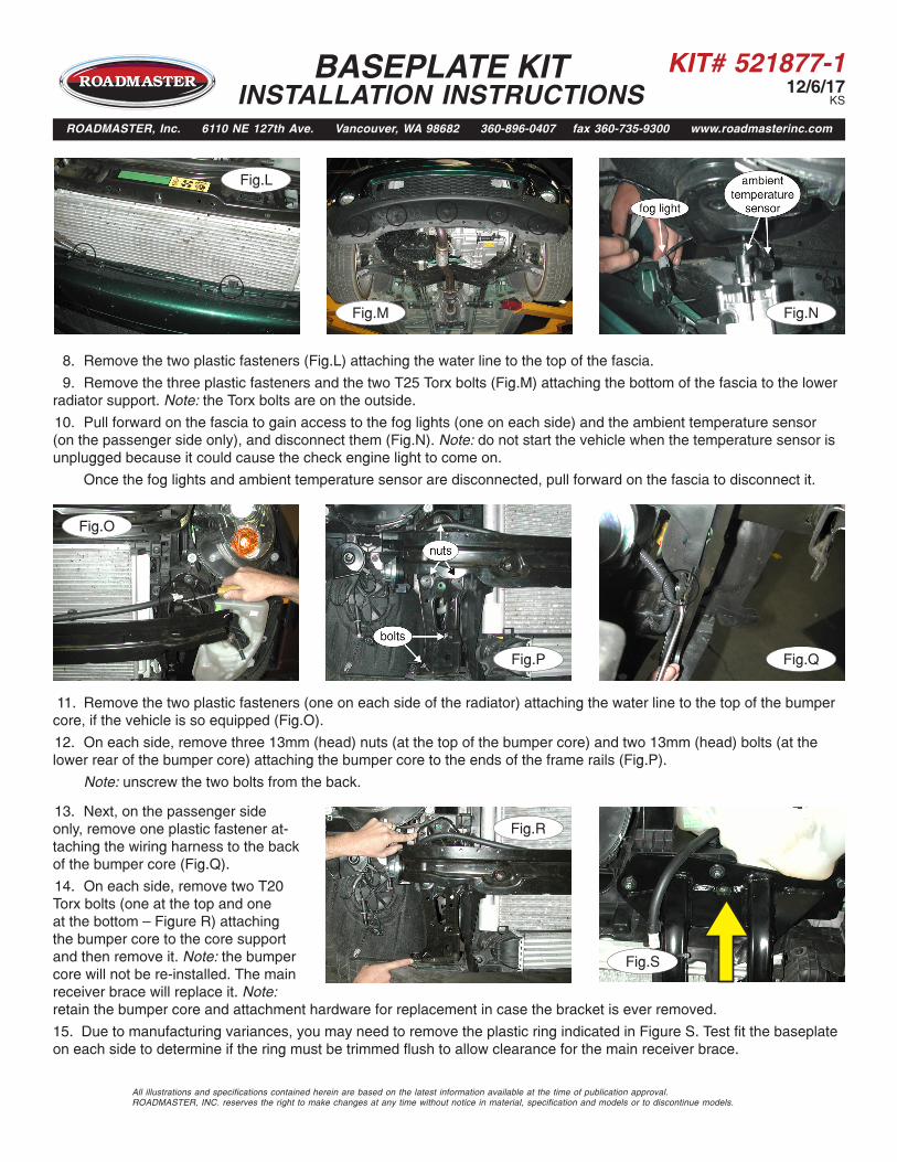
11. Remove the two plastic fasteners (one on each side of the radiator) attaching the water line to the top of the bumper core, if the vehicle is so equipped (Fig.O).
12. On each side, remove three 13mm (head) nuts (at the top of the bumper core) and two 13mm (head) bolts (at the lower rear of the bumper core) attaching the bumper core to the ends of the frame rails (Fig.P).
Note: unscrew the two bolts from the back.
Fig.N
13. Next, on the passenger side only, remove one plastic fastener at-taching the wiring harness to the back of the bumper core (Fig.Q).
14. On each side, remove two T20 Torx bolts (one at the top and one at the bottom — Figure R) attaching the bumper core to the core support and then remove it. Note: the bumper core will not be re-installed. The main receiver brace will replace it. Note:
Fig.Q
Fig.R
Fig.L
Fig.M
8. Remove the two plastic fasteners (Fig.L) attaching the water line to the top of the fascia.
9. Remove the three plastic fasteners and the two T25 Torx bolts (Fig.M) attaching the bottom of the fascia to the lower radiator support. Note: the Torx bolts are on the outside.
10. Pull forward on the fascia to gain access to the fog lights (one on each side) and the ambient temperature sensor (on the passenger side only), and disconnect them (Fig.N). Note: do not start the vehicle when the temperature sensor is unplugged because it could cause the check engine light to come on.
Once the fog lights and ambient temperature sensor are disconnected, pull forward on the fascia to disconnect it.
Fig.S
retain the bumper core and attachment hardware for replacement in case the bracket is ever removed.
15. Due to manufacturing variances, you may need to remove the plastic ring indicated in Figure S. Test fit the baseplate on each side to determine if the ring must be trimmed flush to allow clearance for the main receiver brace.
KIT# 521877-112/6/17
KS
BASEPLATE KIT INSTALLATION INSTRUCTIONS
ROADMASTER, Inc. 6110 NE 127th Ave. Vancouver, WA 98682 360-896-0407 fax 360-735-9300 www.roadmasterinc.com
All illustrations and specifications contained herein are based on the latest information available at the time of publication approval. ROADMASTER, INC. reserves the right to make changes at any time without notice in material, specification and models or to discontinue models.
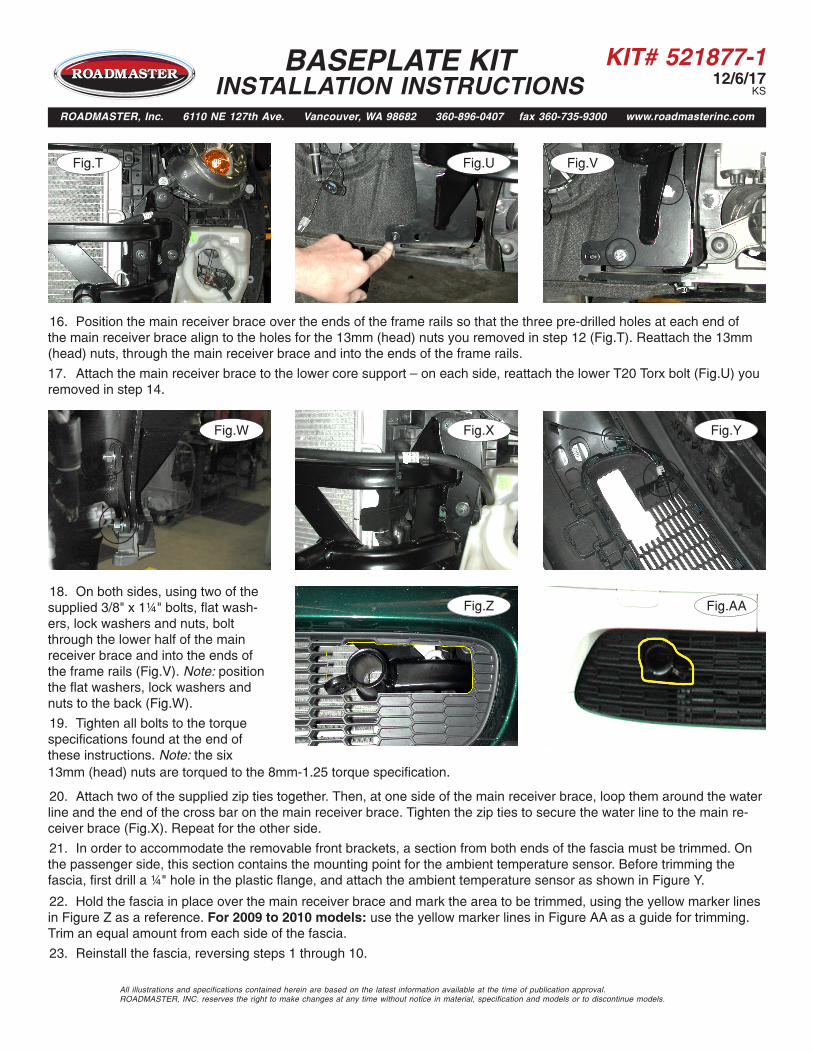
16. Position the main receiver brace over the ends of the frame rails so that the three pre-drilled holes at each end of the main receiver brace align to the holes for the 13mm (head) nuts you removed in step 12 (Fig.T). Reattach the 13mm (head) nuts, through the main receiver brace and into the ends of the frame rails.
17. Attach the main receiver brace to the lower core support — on each side, reattach the lower T20 Torx bolt (Fig.U) you removed in step 14.
Fig.U Fig.V
Fig.W Fig.X Fig.Y
Fig.Z
20. Attach two of the supplied zip ties together. Then, at one side of the main receiver brace, loop them around the water line and the end of the cross bar on the main receiver brace. Tighten the zip ties to secure the water line to the main re-
Fig.T
18. On both sides, using two of the supplied 3/8" x 1¼" bolts, flat wash-ers, lock washers and nuts, bolt through the lower half of the main receiver brace and into the ends of the frame rails (Fig.V). Note: position the flat washers, lock washers and nuts to the back (Fig.W).
19. Tighten all bolts to the torque specifications found at the end of these instructions. Note: the six
22. Hold the fascia in place over the main receiver brace and mark the area to be trimmed, using the yellow marker lines in Figure Z as a reference. For 2009 to 2010 models: use the yellow marker lines in Figure AA as a guide for trimming. Trim an equal amount from each side of the fascia.
23. Reinstall the fascia, reversing steps 1 through 10.
Fig.AA
ceiver brace (Fig.X). Repeat for the other side.
21. In order to accommodate the removable front brackets, a section from both ends of the fascia must be trimmed. On the passenger side, this section contains the mounting point for the ambient temperature sensor. Before trimming the fascia, first drill a ¼" hole in the plastic flange, and attach the ambient temperature sensor as shown in Figure Y.
13mm (head) nuts are torqued to the 8mm-1.25 torque specification.

KIT# 521877-112/6/17
KS
BASEPLATE KIT INSTALLATION INSTRUCTIONS
ROADMASTER, Inc. 6110 NE 127th Ave. Vancouver, WA 98682 360-896-0407 fax 360-735-9300 www.roadmasterinc.com
All illustrations and specifications contained herein are based on the latest information available at the time of publication approval. ROADMASTER, INC. reserves the right to make changes at any time without notice in material, specification and models or to discontinue models.
Fig.BB 24. Insert the removable front brackets into the front receiver braces, and rotate 90 degrees to lock.
25. Install the tow bar to the mounting bracket according to the manufacturer's instructions.
26. Attach the 8" safety cables with the cable connectors (Q-Links) to the front of the receiver braces (Fig.BB).
27. Attach the ends of the safety cables to the tow vehicle's safety cables and tow bar.
BOLT TORQUE REQUIREMENTS
METRIC BOLTSThread Size Grade Torque12mm-1.25 ...........8.8 ............. 64 ft./lb. 12mm-1.5 .............8.8 ............. 60 ft./lb.12mm-1.75 ...........8.8 ............. 55 ft./lb.14mm-2.0 .............8.8 ............. 88 ft./lb.
METRIC BOLTSThread Size Grade Torque6mm-1.0 ............8.8 .............6 ft./lb. 8mm-1.0 ............8.8 ...........18 ft./lb. 8mm-1.25 ..........8.8 ...........16 ft./lb.10mm-1.25 ........8.8 .......... 36 ft./lb.10mm-1.5 ..........8.8 .......... 31 ft./lb.
STANDARD BOLTSThread Size Grade Torque5/16-18 ............5 ................ 13 ft./lb. 3/8-16 ..............5 ................ 23 ft./lb.7/16-14 ............5 ................37 ft./lb.1/2-13 ..............5 ................57 ft./lb.5/8-11 ...............5 .............. 112 ft./lb.
Note: The torque values represented below are intended as general guidelines. Torque requirements for specific applications may vary. Roadmaster does not warrant this information to be accurate for all applications and disclaims all liability for any claims or damages which may result from its use.