Mounting and Repair Instructions - Midwest Indmidwest-ind.com/LENZEGearboxPartsBreakdown.pdf ·...
32
394 835 EN Mounting and Repair Instructions Gearbox Gjj K12.0633
Transcript of Mounting and Repair Instructions - Midwest Indmidwest-ind.com/LENZEGearboxPartsBreakdown.pdf ·...

394 835 EN
Mounting andRepair Instructions
GearboxGjj
K12.0633

O d om^MUMOjj
mêçÇìÅí âÉó
K12.0546
*
Number of stages
Gearbox size
Product family
Product group Gearboxes Input design
Output design
Shaft Output
Solid shaft
Hollow shaft
Hollow shaftwith shrink disk
without flange
flange
Flange with tapped holes
Housing with pitch circle
with centering and foot
with foot (without centering)
with centering (without foot)
without centering (without foot)
Geared motor
Gearbox with bearinghousingfor IEC standard motors
Gearbox with freeinput shaft
Variable speed belt drive
Motor size
Drive size
Drive size
Drive size
1234
GFLKSSSST
M
N
W
K
V
H
S
R
K
L
A
B
C
D
* according to product family
om^ NOKMMMM^ìíÜçêW iÉåòÉ dãÄe C `ç hdIOåÇ ÉÇáíáçåW MRLVV

d om^MUMO Pjj
mçëáíáçå çÑ íÜÉ ëóëíÉã ãçÇìäÉë
GFL GKS / GSS GST
12
3
6
4
5 5
4
6
32
1 1
5
4
6
3
2
k~ãÉéä~íÉ
aÉëáÖå
Field 1Field 2Field 3Field 4Field 5Field 6
i~óçìí
Field Contents Example
1 Manufacturerbuqboq^iLdboj^kv
2 Type Drive size Pos. of the system modules Mounting pos.buqboq^iLdboj^kv
dciMRJO j e`o MUMJPO MMQ _3 Torque M2 in Nm
dciMRJO j e`o MUMJPOOVR kã
MMQ _
4 Speed n2 in 1/min (frequency in Hz)OVR kãOQ Lãáå ERM eòF
5 Ratio Lubricant Week and year of manufacture
E FáZRUISST `imQSM NNVSdqLQMMMMMOT6 Order number Type number dqLQMMMMMOT MMRMMMPU

Contents
Q d om^MUMOjj
N mêÉÑ~ÅÉ ~åÇ ÖÉåÉê~ä áåÑçêã~íáçå RK K K K K K K K K K K K K K K K K K K K K K K K K KNKN eçï íç ìëÉ íÜÉëÉ áåëíêìÅíáçåë RK K K K K K K K K K K K K K K K K K K K K K K K K K K K K K K K K K
NKNKN qÉêãáåçäçÖó L ëáÖåë ìëÉÇ RK K K K K K K K K K K K K K K K K K K K K K K K K K K K K
NKO iÉÖ~ä êÉÖìä~íáçåë RK K K K K K K K K K K K K K K K K K K K K K K K K K K K K K K K K K K K K K K K K K K K K
O p~ÑÉíó áåÑçêã~íáçå SK K K K K K K K K K K K K K K K K K K K K K K K K K K K K K K K K K K K K K K
P bëëÉåíá~ä éêçÅÉÇìêÉë TK K K K K K K K K K K K K K K K K K K K K K K K K K K K K K K K K K K KPKN iìÄêáÅ~åí TK K K K K K K K K K K K K K K K K K K K K K K K K K K K K K K K K K K K K K K K K K K K K K K K K K K K
PKO pÜ~Ñí ëÉ~äë TK K K K K K K K K K K K K K K K K K K K K K K K K K K K K K K K K K K K K K K K K K K K K K K K K K
PKP pÉ~äë TK K K K K K K K K K K K K K K K K K K K K K K K K K K K K K K K K K K K K K K K K K K K K K K K K K K K K K K
PKQ pÅêÉï ÅçååÉÅíáçåë UK K K K K K K K K K K K K K K K K K K K K K K K K K K K K K K K K K K K K K K K K K K
PKR mìëÜJáå éáåáçå UK K K K K K K K K K K K K K K K K K K K K K K K K K K K K K K K K K K K K K K K K K K K K K K
Q aáëã~åíäáåÖ VK K K K K K K K K K K K K K K K K K K K K K K K K K K K K K K K K K K K K K K K K K K K KQKN fåéìí ÅçãéçåÉåíë djj VK K K K K K K K K K K K K K K K K K K K K K K K K K K K K K K K K K K K K K
QKNKN aÉëáÖå j VK K K K K K K K K K K K K K K K K K K K K K K K K K K K K K K K K K K K K K K K K K KQKNKO aÉëáÖå k NMK K K K K K K K K K K K K K K K K K K K K K K K K K K K K K K K K K K K K K K K K K KQKNKP aÉëáÖå t NOK K K K K K K K K K K K K K K K K K K K K K K K K K K K K K K K K K K K K K K K K K K
QKO fåéìí ëí~ÖÉ djj NQK K K K K K K K K K K K K K K K K K K K K K K K K K K K K K K K K K K K K K K K K K K K
QKP lìíéìí ÅçãéçåÉåíë NRK K K K K K K K K K K K K K K K K K K K K K K K K K K K K K K K K K K K K K K K K KQKPKN aÉëáÖå sjh L sji L ejh L pjh NRK K K K K K K K K K K K K K K K K K K K K KQKPKO aÉëáÖå sjo L ejo L pjo NSK K K K K K K K K K K K K K K K K K K K K K K K K K K KQKPKP cççí ãçìåíáåÖ j^jL j_j Eçåäó dciF NSK K K K K K K K K K K K K K K K K
QKQ _~ëÉ ÖÉ~êÄçñ EïáíÜçìí áåéìí ~åÇ çìíéìí ÅçãéçåÉåíëF NTK K K K K K K K K K K K KQKQKN dpq jjJN NTK K K K K K K K K K K K K K K K K K K K K K K K K K K K K K K K K K K K K K K K KQKQKO dpq jjJOX dpq jjJP NUK K K K K K K K K K K K K K K K K K K K K K K K K K K K K KQKQKP dci jjJOX dci jjJP OMK K K K K K K K K K K K K K K K K K K K K K K K K K K K K KQKQKQ dpp jjJOX dpp jjJP OOK K K K K K K K K K K K K K K K K K K K K K K K K K K K K KQKQKR dhp jjJPX dhp jjJQ OQK K K K K K K K K K K K K K K K K K K K K K K K K K K K K K
R qÉÅÜåáÅ~ä áåÑçêã~íáçå OUK K K K K K K K K K K K K K K K K K K K K K K K K K K K K K K K K K K KRKN ^ñá~ä ÅäÉ~ê~åÅÉ çÑ íÜÉ ëÜ~Ñíë OUK K K K K K K K K K K K K K K K K K K K K K K K K K K K K K K K K K K K
RKO ^ñá~ä éçëáíáçå çÑ íÜÉ ÄÉîÉä éáåáçå OUK K K K K K K K K K K K K K K K K K K K K K K K K K K K K K K K
RKP ^ñá~ä éçëáíáçå çÑ íÜÉ ÄÉîÉä ÖÉ~ê OUK K K K K K K K K K K K K K K K K K K K K K K K K K K K K K K K K
RKQ gçáåáåÖ ÑçêÅÉë Ñçê ÖÉ~êë OVK K K K K K K K K K K K K K K K K K K K K K K K K K K K K K K K K K K K K K K
RKR gçáåáåÖ éìëÜJáå éáåáçåë áíÉã OMNLSMO OVK K K K K K K K K K K K K K K K K K K K K K K K K K K
RKS oáåÖ áíÉãNOQLNOS OVK K K K K K K K K K K K K K K K K K K K K K K K K K K K K K K K K K K K K K K K K K K K
S pé~êÉ é~êíë çêÇÉê PMK K K K K K K K K K K K K K K K K K K K K K K K K K K K K K K K K K K K K K K KSKN lêÇÉê Ñçêã PMK K K K K K K K K K K K K K K K K K K K K K K K K K K K K K K K K K K K K K K K K K K K K K K K K K
j~åìÑ~ÅíìêÉêÛë `ÉêíáÑáÅ~íáçå
pÉêîáÅÉ ~ÇÇêÉëëÉë

Preface and general information
d om^MUMO Rjj
N mêÉÑ~ÅÉ ~åÇ ÖÉåÉê~ä áåÑçêã~íáçå
NKN eçï íç ìëÉ íÜÉëÉ áåëíêìÅíáçåë
D qÜÉëÉ áåëíêìÅíáçåë ~êÉ ~ ëìééäÉãÉåí íç íÜÉ ÖÉ~êÄçñ çéÉê~íáåÖáåëíêìÅíáçåë djj ~åÇ ~êÉ î~äáÇ çåäó íçÖÉíÜÉê ïáíÜ íÜÉëÉ çéÉê~íáåÖáåëíêìÅíáçåëK
D qÜÉëÉ áåëíêìÅíáçåë ~êÉ áåíÉåÇÉÇ Ñçê íÜÉ ëéÉÅá~äáëíI ~ë ~å ~áÇ Ñçê íÜÉÇáëã~åíäáåÖ ~åÇ ãçìåíáåÖ çÑ íÜÉ ÖÉ~êÄçñ ÅçãéçåÉåíëKJ tÉ êÉÅçããÉåÇ íÜ~í êÉé~áêë ~êÉ Å~êêáÉÇ çìí Äó iÉåòÉ pÉêîáÅÉK
D ^ää éÉêëçåë ïçêâáåÖ çå ~åÇ ïáíÜ íÜÉ ÖÉ~êÄçñÉë djj ãìëí Ü~îÉ íÜÉáåëíêìÅíáçåë ~î~áä~ÄäÉ ~åÇ ãìëí çÄëÉêîÉ íÜÉ áåÑçêã~íáçå ~åÇ åçíÉëêÉäÉî~åí Ñçê íÜÉáê ïçêâK
D qÜÉ áåëíêìÅíáçåë ãìëí ~äï~óë ÄÉ áå ~ ÅçãéäÉíÉ ~åÇ éÉêÑÉÅíäó êÉ~Ç~ÄäÉëí~íÉK
NKNKN qÉêãáåçäçÖó L páÖåë ìëÉÇ
Terminology / Sign Meaning in the textGjj All families of the Gearbox product group of the new generation
Gearbox Gearbox of the product family Gjj
Drive system Drive systems with gearboxes Gjj and other Lenze drive components
➡ Cross reference
NKO iÉÖ~ä êÉÖìä~íáçåë
iá~Äáäáíó
D qÜÉ áåÑçêã~íáçåI Ç~í~I ~åÇ åçíÉë áå íÜÉ áåëíêìÅíáçåë ãÉí íÜÉ ëí~íÉ çÑ íÜÉ~êí ~í íÜÉ íáãÉ çÑ éêáåíáåÖK `ä~áãë êÉÑÉêêáåÖ íç ÇêáîÉ ëóëíÉãë ïÜáÅÜ Ü~îÉ~äêÉ~Çó ÄÉÉå ëìééäáÉÇ Å~ååçí ÄÉ ÇÉêáîÉÇ Ñêçã íÜÉ áåÑçêã~íáçåIáääìëíê~íáçåëI ~åÇ ÇÉëÅêáéíáçåëK
D aç åçí Çáëã~åíäÉ íÜÉ ÇêáîÉ ïáíÜáå íÜÉ ï~êê~åíó éÉêáçÇK

Safety information
S d om^MUMOjj
O p~ÑÉíó áåÑçêã~íáçå
dÉåÉê~ä ë~ÑÉíó áåÑçêã~íáçå
D qÜÉ ë~ÑÉíó áåÑçêã~íáçå áå íÜÉëÉ áåëíêìÅíáçåë áë åçí Åä~áãÉÇ íç ÄÉÅçãéäÉíÉK få Å~ëÉ çÑ èìÉëíáçåë ~åÇ éêçÄäÉãë éäÉ~ëÉ Åçåí~Åí óçìêiÉåòÉ êÉéêÉëÉåí~íáîÉK
D få ~ÇÇáíáçåI çÄëÉêîÉ íÜÉ ë~ÑÉíó áåÑçêã~íáçå áå íÜÉ çéÉê~íáåÖ áåëíêìÅíáçåëK
D kÉîÉê Çáëã~åíäÉ íÜÉ ÇêáîÉ ïÜÉå áåëí~ääÉÇ áå íÜÉ ã~ÅÜáåÉK
i~óçìí çÑ íÜÉ ë~ÑÉíó áåÑçêã~íáçå
^ää ë~ÑÉíó áåÑçêã~íáçå áå íÜÉëÉ áåëíêìÅíáçåë Ü~ë ~ ìåáÑçêã ä~óçìíW
páÖå~ä ïçêÇkçíÉë
J qÜÉ áÅçå ÇÉëáÖå~íÉë íÜÉ íóéÉ çÑ Ç~åÖÉêKJ qÜÉ ëáÖå~ä ïçêÇ ÇÉëáÖå~íÉë íÜÉ ëÉîÉêáíó çÑ Ç~åÖÉêKJ qÜÉ åçíÉ ÇÉëÅêáÄÉë íÜÉ Ç~åÖÉê ~åÇ ëìÖÖÉëíë Üçï íç ~îçáÇ íÜÉÇ~åÖÉêK
t~êåáåÖ çÑ Ç~åÖÉê Ñçê éÉêëçåë
Icons used Signal words
Warning ofhazardous electrical
Danger! Warns of impending danger.Consequences when disregarded:hazardous electrical
voltageConsequences when disregarded:Death or very severe injuries.
Warning of ageneral danger
Warning! Warns of a potential, very hazardous situation.Possible consequences when disregarded:Death or very severe injuries.
Caution! Warns of a potential, hazardous situation.Possible consequences when disregarded:Light or minor injuries.
t~êåáåÖ çÑ ã~íÉêá~ä Ç~ã~ÖÉ
Icons used Signal words
Stop! Warns of potential material damage.Possible consequences when disregarded:Damage to the drive system/device or its environmentK
líÜÉê åçíÉë
Icons used Signal words
Tip! Designates a general, useful tip.If you observe it, handling of the drive system/device is madeeasier.

Essential procedures
d om^MUMO Tjj
P bëëÉåíá~ä éêçÅÉÇìêÉëD vçì Å~å Çáëã~åíäÉ áåÇáîáÇì~ä ÅçãéçåÉåíë çÑ ÖÉ~êÄçñÉë ~åÇ ÖÉ~êÉÇ
ãçíçêëI íÜÉ áåëíêìÅíáçåë ~êÉ ëíêìÅíìêÉÇ ~ÅÅçêÇáåÖäóK
D qÜÉ áåëíêìÅíáçåë ÇÉëÅêáÄÉ áå íÜÉ ëÉèìÉåÅÉ çÑ Çáëã~åíäáåÖI Ñçê íÜÉ~ëëÉãÄäó éêçÅÉÉÇ áå íÜÉ êÉîÉêëÉ ëÉèìÉåÅÉK
D qêçìÄäÉëÜççíáåÖ ~åÇ Ñ~ìäí Éäáãáå~íáçå ➡ léÉê~íáåÖ áåëíêìÅíáçåë
D oÉÅçããáëëáçåáåÖ ➡ léÉê~íáåÖ áåëíêìÅíáçåë
D t~ëíÉ Çáëéçë~ä ➡ léÉê~íáåÖ áåëíêìÅíáçåë
D pÉêîáÅÉ ~ÇÇêÉëëÉë ➡ léÉê~íáåÖ áåëíêìÅíáçåë
PKN iìÄêáÅ~åíë
D aê~áå çÑÑ íÜÉ äìÄêáÅ~åí éêáçê íç Çáëã~åíäáåÖK
D oÉÑáää ~ÑíÉê ãçìåíáåÖ ➡ léÉê~íáåÖ áåëíêìÅíáçåëI j~áåíÉå~åÅÉ ÅÜ~éíÉêJ péÉÅáÑáÅ~íáçåW ➡ k~ãÉéä~íÉ ~åÇ çéÉê~íáåÖ áåëíêìÅíáçåëK
PKO pÜ~Ñí ëÉ~äë
D aç åçí Ç~ã~ÖÉ íÜÉ ëìêÑ~ÅÉ çå ïÜáÅÜ íÜÉ ëÜ~Ñí ëÉ~ä êìåëK
D dêÉ~ëÉ ëÜ~Ñí ëÉ~ä äáé ïÜÉå ãçìåíáåÖK
D fåëÉêí ëÜ~Ñí ëÉ~ä éêçéÉêäóK
D aç åçí ãçìåí ëÉ~ä äáé çå êìåJáå ã~êâëI áÑ ~åóKJ fÑ åÉÅÉëë~êóI êÉÖêáåÇ ëÜ~Ñí ïáíÜçìí ÅÜ~ííÉê ã~êâëK
D mêçíÉÅí ëÜ~Ñí ëÉ~ä Ñêçã Ç~ã~ÖÉ Å~ìëÉÇ Äó ëÜ~Ñí âÉóï~óëKJ ÉKÖK Äó ÅçîÉêáåÖ çÑ íÜÉ ëÜ~Ñí âÉóï~ó ìëáåÖ ~ÇÜÉëáîÉ í~éÉ
PKP pÉ~äë
D `çãéäÉíÉäó êÉãçîÉ ëÉ~äëK
D `äÉ~å ëÉ~ä ëìêÑ~ÅÉëK
D oÉéä~ÅÉ ëÉ~äëK
Essential procedures
U d om^MUMOjj
PKQ pÅêÉï ÅçååÉÅíáçåë
D pÉÅìêÉ ëÅêÉï ÅçååÉÅíáçåë ~ééêçéêá~íÉäóK
D tÉ êÉÅçããÉåÇ ÖäìáåÖ ëÅêÉï ÅçååÉÅíáçåëK
PKR mìëÜJáå éáåáçå
qç Çáëã~åíäÉ íÜÉ ÇêáîÉ ëÜ~ÑíI êçääÉê ÄÉ~êáåÖëI ~åÇ ëÜ~Ñí ëÉ~äëI áí ã~ó ÄÉ åÉÅÉëë~êóíç Çáëã~åíäÉ íÜÉ éìëÜJáå éáåáçåI áíÉã OMNLSMOK
D aêáîÉ ÅçãéçåÉåíë ïÜáÅÜ Ü~îÉ ~ éìëÜJáå éáåáçå ïáíÜ ~ ëã~ääÉê íáéÇá~ãÉíÉê íÜ~å íÜÉ áååÉê Çá~ãÉíÉê çÑ íÜÉ êçääÉê ÄÉ~êáåÖWJ qÜÉëÉ ÇêáîÉ ÅçãéçåÉåíë Å~å ÄÉ Çáë~ëëÉãÄäÉÇ ïáíÜçìí Çáëã~åíäáåÖ íÜÉéáåáçåK
D aêáîÉ ÅçãéçåÉåíë ïÜáÅÜ Ü~îÉ ~ éìëÜJáå éáåáçå ïáíÜ ä~êÖÉê íáé Çá~ãÉíÉêíÜ~å íÜÉ áååÉê Çá~ãÉíÉê çÑ íÜÉ êçääÉê ÄÉ~êáåÖWJ qÜÉëÉ ÇêáîÉ ÅçãéçåÉåíë Å~å çåäó ÄÉ Çáë~ëëÉãÄäÉÇ ~ÑíÉê Çáëã~åíäáåÖíÜÉ éáåáçåK
J tÉ êÉÅçããÉåÇ íÜ~í íÜÉëÉ êÉé~áêë ~êÉ ÇçåÉ Äó íÜÉ iÉåòÉ pÉêîáÅÉIëáåÅÉ ëéÉÅá~ä íççäë ~êÉ åÉÅÉëë~êó Ñçê Çáë~ëëÉãÄäáåÖ íÜÉ éáåáçåKlíÜÉêïáëÉI íÜÉ éìëÜJáå éáåáçå ã~ó ÄÉ ÇÉëíêçóÉÇ ÇìêáåÖ Çáëã~åíäáåÖK

Dismantling
d om^MUMO Vjj
Q aáëã~åíäáåÖ
QKN fåéìí ÅçãéçåÉåíë djj
QKNKN aÉëáÖå j
dÉ~êÉÇ ãçíçê
➡ cáÖK N
Sequence of dismantling Item1. Disconnect motor from the supply voltage ➡ Operating instructions - motor 301
2. Loosen hexagon head head screw / hexagon head nut and remove 221 / 222
3. Separate motor and gearbox 301
4. Remove O-ring 220
5. Dismantling of push-in pinion ➡ chapter 3.5( in case of assembly ➡ chapter 5.5) 201
K12.0553
301
221 222221
201
220
cáÖK N dÉ~êÉÇ ãçíçê

Dismantling
NM d om^MUMOjj
QKNKO aÉëáÖå k
dÉ~êÄçñ ïáíÜ ÄÉ~êáåÖ ÜçìëáåÖ Ñçê fb` ëí~åÇ~êÇ ãçíçêë
➡ cáÖK O L cáÖK P
Sequence of dismantling Drive size1A to 1G 1H to 2K
Item1. Disconnect motor from the supply voltage ➡ Motor operating instructions
2. Motor dismantling / assembly ➡ Motor operating instructions
3. Remove motor from the bearing housing
4. Remove coupling element 531
5. Loosen hexagon head screw / hexagon head nut and remove 221 / 222
6. Remove drive component from the gearbox 501
7. Remove O-ring 220
8. Dismantling of push-in pinion ➡ chapter 3.5( in case of assembly ➡ chapter 5.5) 201
9. Pull off oil slinger and remove 527 ---
10. Remove circlip 522 525
11. Remove shim ( for assembly ➡ chapter 5.1 ) --- 526
12. Press shaft out of the housing towards the input 510
13. Remove shaft seal and replace 521 ---
14. Pull deep groove ball bearing off the shaft 520 ---
15. Remove circlips 525 ---
16. for drive size 1G: Remove shim ( for assembly ➡ chapter 5.1 ) 526 ---
17. Pull deep groove ball bearing off the shaft 523 ---
18. Remove inner ring of the tapered roller bearing --- 520
19. Pull remaining inner ring of the tapered roller bearing off the shaft --- 523
20. Press out cover --- 528
21. Press out outer ring of the tapered roller bearing --- 520
22. Press out outer ring of the tapered roller bearing (with slinger in mounting position C) --- 523 + 540
23. in mounting position C: Replace slinger --- 540
Observe for the assembly1. in mounting position C: Remove spring from the shaft seal --- 521
2.Spaces and tapered roller bearings are 40% filled with greasee.g. Klüber Mircolube GLY92
--- 541

Dismantling
d om^MUMO NNjj
K12.0554
525 525 522 532
501
521
201
527520
220
222
221510 526 523 531 530
cáÖK O aêáîÉ ëáòÉ N^ íç Nd
K12.0555
221
220501
523
540520526
201
510
525528
541
521 531 530
221 222
550 551
cáÖK P aêáîÉ ëáòÉ Ne íç Oh

Dismantling
NO d om^MUMOjj
QKNKP aÉëáÖå t
dÉ~êÄçñ ïáíÜ ÑêÉÉ áåéìí ëÜ~Ñí
➡➡➡➡ cáÖK Q L cáÖK R
Sequence of dismantling Drive size1A to 1F 1G to 1K
Item1. Loosen hexagon head screw / hexagon head nut and remove 221 / 222
2. Remove drive component from the gearbox 401
3. Remove O-ring (remove seal for drive size 1A and 1B) 220
4. Remove feather 427
5. Remove shaft seal and replace 426
6. Dismantling of push-in pinion ➡ chapter 3.5 (in case of assembly ➡ chapter 5.5) --- 201
7. Remove circlip 425
8. Remove shim (for assembly ➡ chapter 5.1 ) 424
9.for drive size 1A to 1F: Press shaft out of the housing towards the outputfor drive size 1G to 2K: Press shaft out of the housing towards the input
410
10. for drive size 1C to 1F: Remove shaft seal and replace 421 ---
11. Remove circlips 422 ---
12. Press deep groove ball bearing out of the housing 423 ---
13. Dismantling of push-in pinion ➡ chapter 3.5 (in case of assembly ➡ chapter 5.5) 201 ---
14. Pull deep groove ball bearing off the shaft 420 ---
15. Remove inner ring of the tapered roller bearing --- 420
16. Pull remaining inner ring of the tapered roller bearing off the shaft --- 423
17. Press out cover --- 428
18. Press out outer ring of the tapered roller bearing --- 420
19. Press out outer ring of the tapered roller bearing (with slinger in mounting position C) --- 423 + 440
20. in mounting position C: Replace slinger --- 440
Observe for the assembly1. in mounting position C: Remove spring from the shaft seal --- 426
2.Spaces and tapered roller bearings are 40% filled with greasee.g. Klüber Microlube GLY92
--- 441
3. Secure inner ring of the deep groove ball bearing with suitable adhesive 420 ---

Dismantling
d om^MUMO NPjj
K12.0556
401
420
201
421
220
221
422 424
425
410 427
426
423
222221
cáÖK Q aêáîÉ ëáòÉ N^ íç Nc
K12.0557
221
220
420424
201
425
428
401
222221
440426
410
427
423
441
cáÖK R aêáîÉ ëáòÉ Nd íç Nh

Dismantling
NQ d om^MUMOjj
QKO fåéìí ëí~ÖÉ djj
➡ cáÖK SSequence of dismantling Item1. Loosen allen screw and remove 613
2. Remove cover from the housing attachment 612
3. Remove seal 614
4. Loosen allen screw and remove 604 + 605
5. Remove input stage from the gearbox 601
6. Dismantling of push-in pinion ➡ chapter 3.5 (in case of assembly ➡ chapter 5.5) 602
7. Remove circlip 625
8. Remove shim 626
9. Press shaft out of the housing towards the input 610
10. Place gear and press out shaft ➡ chapter 5.4 610 from 603
11. Remove shim 624
12. Pull deep groove ball bearing off the shaft 623
13. Press deep groove ball bearing out of the housing 620
14. Remove circlip 622
15. Remove shaft seal and replace (for assembly ➡ table) 621
Observe for the assemblyGearbox size 06 07 09 11 14
Distance w 4 mm 4 mm 9 mm 9 mm 18 mm
K12.0558
613605
604
618
630
631 615612
603623
610
624
621 622 614
620
626
602
625
601
cáÖK S fåéìí ëí~ÖÉ Ñçê djj

Dismantling
d om^MUMO NRjj
QKP lìíéìí ÅçãéçåÉåíë
kçíÉ>aÉÑÉÅíáîÉ ëÜ~Ñí ëÉ~äë Å~å ÄÉ êÉéä~ÅÉÇ ïáíÜçìí Çáëã~åíäáåÖ íÜÉ ÖÉ~êÄçñK➡ aáëã~åíäáåÖ çÑ íÜÉ Ä~ëÉ ÖÉ~êÄçñ çÑ íÜÉ ÅçêêÉëéçåÇáåÖ éêçÇìÅí Ñ~ãáäóEÅÜ~éíÉê QKQ ÑÑKFK
píçé>mêáçê íç Çáëã~åíäáåÖ íÜÉ ëÜêáåâ Çáëâ áíÉã NNO E cáÖK V LcáÖK NM LcáÖK NN F íÜÉçéÉê~íáåÖ áåëíêìÅíáçåë çÑ íÜÉ ÖÉ~êÄçñ ãìëí ÄÉ çÄëÉêîÉÇ áå ~ää Å~ëÉëK
QKPKN aÉëáÖå sjh L sji L ejh L pjh
pçäáÇ ëÜ~ÑíïáíÜ Ñä~åÖÉ Leçääçï ëÜ~ÑíïáíÜ Ñä~åÖÉ L eçääçïëÜ~ÑíïáíÜ ëÜêáåâÇáëâ ~åÇ Ñä~åÖÉ
➡ cáÖK T LcáÖK U L cáÖK V LcáÖK NM LcáÖK NN
Sequence of dismantling GearboxGFL / GSS / GKS GST
DesignVjK HjK / SjK VjK / VjL
Item1. Remove key from the shaft 136 --- 136
2. Loosen allen screws and remove 173 172 173
3. Remove flange 110 109 110 / 109
4. Remove seal and replace 161 ---
5. Remove shaft seal and replace 129 128 125
6. Remove shim (for assembly ➡ chapter 5.1) 157 --- ---
7. Remove shaft seal / cover and replace 131 127 ---
8. Further sequence of dismantling ➡ chapter 4.4

Dismantling
NS d om^MUMOjj
QKPKO aÉëáÖå sjo L ejo L pjo
pçäáÇ ëÜ~Ñí ïáíÜçìí Ñä~åÖÉ L eçääçï ëÜ~Ñí ïáíÜçìí Ñä~åÖÉeçääçï ëÜ~Ñí ïáíÜ ëÜêáåâ Çáëâ ïáíÜçìí Ñä~åÖÉ
➡ cáÖK T L cáÖK U L cáÖK V L cáÖK NM L cáÖK NN
Sequence of dismantling GearboxGFL / GSS / GKS GST
DesignVjR HjR / SjR VjR
Item1. Remove key from the shaft 136 --- 136
2. Remove shaft seal / cover and replace 131 127 ---
3. Remove shaft seal and replace 125
4. Further sequence of dismantling ➡ chapter 4.4
QKPKP cççí ãçìåíáåÖ j^j L j_jEçåäó dciF
➡ cáÖK V
Sequence of dismantling Item1. Loosen allen screws and remove 174
2. Remove feet from the base gearbox 111
3. Further sequence of dismantling ➡ chapter 4.4.3

Dismantling
d om^MUMO NTjj
QKQ _~ëÉ ÖÉ~êÄçñEïáíÜçìí áåéìí ~åÇ çìíéìí ÅçãéçåÉåíëF
QKQKN dpq jjJN
➡ cáÖK T
Sequence of dismantling Item1. Loosen allen screw and remove 203
2. Remove cover 202
3. Remove seal 204
4. Remove pin 205
5. Pull off gear with special tool ➡ chapter 5.4 103
6. Remove shim 151
7. Press shaft out of the housing towards the output 106 from 101
8. Pull off deep groove ball bearing 118
9. Remove bushing 107
10. Remove circlip 141
11. Pull of deep groove ball bearing 117
K12.0559
209
107
110
173
125
136
106117
141
101 204
203
208
202
151
118
103
205
cáÖK T dpq jjJN

Dismantling
NU d om^MUMOjj
QKQKO dpq jjJOX dpq jjJP
➡ cáÖK U
Sequence of dismantling Item
1. - 4. only for GST jj-2
normal bearing reinforced bea-ring and size
11/14
1. Loosen allen screws and remove 203
2. Remove cover 202
3. Remove seal 204
4. Remove pin 205
5. Remove cover 130
6. Remove circlip 140
7. Remove shim 150
8. Press pinion shaft with gear out of the housing towards the input 103 + 104 out of 101
9. Press pinion shaft out of the gear ➡ chapter 5.4 103
10. Remove shim 151
11. Pull off deep groove ball bearing 116
12. Loosen screws and remove 172
13. Press shaft with gear and cover out of the housing towards the input 106+105+102 out of 101
14. Remove cover --- 102
15. Remove circlip 143 142
16. Remove shim (for assembly ➡ chapter 5.1) 152 153
17. Pull off outer and inner ring of the tapered roller bearing --- 118
18. for size 11/14: Remove shim (for assembly ➡ chapter 5.1) --- 152
19. for size 11/14: Remove circlip --- 143
20. Press shaft out of the gear and cover ➡ chapter 5.4106 out of105+102
106 out of 105
21. for size 11/14: Remove key --- 135
22. Pull off bushing --- 107
23. Pull off inner and outer ring of the tapered roller bearing --- 117
24. Remove circlip 142 ---
25. Pull off deep groove ball bearing 118 ---
26. Pull off deep groove ball bearing 117 ---
27. Remove circlip 141
28. Pull off deep groove ball bearing 115
Observe for the assemblySize 04:Distance X between deep groover roller bearing and gear: 3.0 mm ➡ Fig. 8Distance X between tapered roller bearing and gear: 1.8 mm ➡ Fig. 8
118 +105
Size 11/14 and reinforced bearing:Inner ring must not contact the shaft shoulderPress in inner ring, bushing, gear, and inner ring together
117 at 106117+107+105+118

Dismantling
d om^MUMO NVjj
K12.0559/1
Detail A - only size 04 Detail B - only size 04 Detail C - only size 11 and 14
110 209 105 142 102 172 205
117
173
125106
136135
140
130
150
101 141 104 116 151 204 203
208
202
103
152
143
118
Detail A
107 102 172
117
127
153
118
142
Detail B + C
Normaloutput shaft bearinggearbox size 04 - 09
Reinforcedoutput shaft bearinggearbox size 04 - 14
135
143
152
cáÖK U dpq jjJOX dpq jjJP

Dismantling
OM d om^MUMOjj
QKQKP dci jjJOX dci jjJP
➡ cáÖK V
Sequence of dismantling Item1. - 3. only necessary when replacing gear (item 103), pinion shaft (item 104),
tapered roller bearing (item 115 or item 116)
1. Remove cover 130
2. Remove circlip 140
3. Remove shim (for assembly ➡ chapter 5.1) 155
4. Loosen allen screws and remove 170 / 171
5. Turn the gearbox on its side (position 3 or 5 of the system modules)
6.Separate the two parts of the housing: For this, you can lightly hammer on the front part of theoutput shaft (position 6 of the system modules) using a plastic hammer
101 and 102106 / 107 / 108
7. Turn the housing on the input side (position 1 of the system modules) 101
8. Remove housing 102
9. Remove seal 160
10Press shaft out of the housing and 107 / 108 / 106 out of 101
10.Press shaft out of the housing andremove pinion shaft
107 / 108 / 106 out of 101104
11. Pull off inner rings of the tapered roller bearings 115 + 116
12. for gearbox sizes 05/06/07: Remove shim 150
13. Pull off gear ➡ chapter 5.4 103
14. for gearbox size 09: Remove shim 151
15. Remove outer ring of the tapered roller bearing 116
16. Remove outer ring of the tapered roller bearing 115
17. Pull off deep groove ball bearing or outer and inner ring of the tapered roller bearing 117 / 119
18.for output design VjR; Hjj; Sjj:Remove shim (for assembly ➡ chapter 5.1)
156
19. Pull off deep groove ball bearing or outer and inner ring of the tapered roller bearing 118
20. for output design VjK: Remove circlip 144
21. Pull off gear 105
22. Remove keys 135
23. Remove circlips 142 + 143
24. Remove circlip 141
25. for gearbox size 11/14: Press out ring (for assembly ➡ chapter 5.6) 126
26. - 29. only for GFL jj-2Removing the cover item 202 is normally not required
26. Loosen allen screw 203
27. Remove cover 202
28. Remove seal 204
29. Remove pin 205
Observe for the assemblyFor gearbox size 14, design VDR: Press in outer ring of the tapered roller bearing after mounting the twoparts of the housing
117 after101 + 102
Press in outer ring of the tapered roller bearing after mounting the two parts ofthe housing 115 after 101 + 102
For gearbox size 11 and 14 press in ring after adjusting the clearance of the output shaft or the hollowshaft ➡ chapter 5.6 126

Dismantling
d om^MUMO ONjj
K12.0560
174
111 171 209
208 170
112
106 113
165 204151(size 09)
102
140
115
130
155
141
136
107125
126
156 117 105 160 135 142
205
202
101
103150size 05/06/07
104
116
203
127
106
143
131
118
Output designSjj
Output designjjK
109
172
128
136
108 129
119
157
173
110161 144
cáÖK V içïJéêçÑáäÉ ÖÉ~êÄçñ

Dismantling
OO d om^MUMOjj
QKQKQ dpp jjJOX dpp jjJP
➡ cáÖK NM
Sequence of dismantling Item1. Loosen allen screws and remove 170
2. Remove cover 102
3. Remove seal 160
4. Remove circlip 145
5. For output design VjK: Pull off deep groove ball bearing 119
6. For output design VjK: Remove circlips 144
7. Support worm gear with suitable attachment in the housing 105 in 101
8. Press shaft out of the housing 107 / 108 / 106 out of 101
9. Remove worm gear and attachment 105
10. Remove keys 135
11. Remove circlips 142 + 143
12. Pull off deep groove ball bearing 118
13. Remove circlip 141
14.not for output design VjKRemove shim (for assembly ➡ chapter 5.1) 156
15. Pull off deep groove ball bearing 117
16. - 22.only necessary when replacing gear (item 103), pinion shaft (item 104),tapered roller bearing (item 115 or item 116)
16. Remove cover 130
17. Remove circlip 140
18. Remove shim (for assembly ➡ chapter 5.1) 155
19. - 22.only for GSS jj-219. Loosen allen screw 203
20. Remove cover 202
21. Remove seal 204
22. Remove pin 205
23. Pull off gear ➡ chapter 5.4 103
24. Press out worm shaft 104
25. Remove outer ring of the tapered roller bearing 115
26. Pull off inner rings of the tapered roller bearings 115 +116
27. Remove circlips 139
28. Remove outer ring of the tapered roller bearing 116

Dismantling
d om^MUMO OPjj
K12.0561
156 135 105 142
117
136
107 125
141
101
156
127
118
106
143
131
145
161109
172
128
136 108
129
119
157
173
110
144
112
113
106
155 115 104 116 139 103 204 203
208
202
205
160102209170
140
130
Output designjjK
Output design Sjj
cáÖK NM eÉäáÅ~ä ïçêã ÖÉ~êÄçñ

Dismantling
OQ d om^MUMOjj
QKQKR dhp jjJPX dhp jjJQ
➡ cáÖK NN LcáÖK NO
Sequence of dismantling Output design
VjR VjKHjRSjR
HjKSjK
VjR VjK
Position of the system modules3jj 3jj + 5jj 5jj
Item1. Loosen allen screws and remove 170
2. Remove cover 102
3. Remove seal 160
205
170 209 102 160
111 153 120 158 159 121 204203
208
202
112
106 113
103 K12.0562
cáÖK NN eÉäáÅ~ä ÄÉîÉä ÖÉ~êÄçñ
píçé>qÜÉ ÑçääçïáåÖ ëíÉéë êÉèìáêÉ ëéÉÅá~ä íççäëK oÉé~áêë ëÜçìäÇ íÜÉêÉÑçêÉ çåäó ÄÉ Å~êêáÉÇçìí Äó iÉåòÉ pÉêîáÅÉ>

Dismantling
d om^MUMO ORjj
Sequence of dismantling Output design
VjR VjKHjRSjR
HjKSjK
VjR VjK
Position of the system modules3jj 3jj + 5jj 5jj
Item
4.For gearbox size 11/14: Pull off ring (for assembly➡ chapter 5.6) 126 --- 126 --- --- ---
5. Remove circlip 141 --- 141 145
6. Pull off deep groove ball bearing --- --- --- 119
7. Remove circlips --- --- --- 144
8. Remove shim (for assembly ➡ chapter 5.1) 156 --- 156 ---
9. Support gear with suitable attachment in the housing 105 in 101
10. Press shaft out of the housing towards the bevel gear 107 108 106 107 108
11.For gearbox size 14 or reinforced bearing:Remove outer ring of the tapered roller bearingRemove inner ring of the tapered roller bearing
117118
------
------
118117
------
12. Remove gear 105
13. Remove attachment for gear support
14. For gearbox size 05 to 11: Pull off deep groove ball bearing 117 119 117 118 118
15. Remove keys 135
16. Remove circlips 142
17. Remove circlips 143 --- 143 146
18.For gearbox size 14 or reinforced bearing:Pull off inner ring of the tapered roller bearing
117 --- --- 118 ---
19.For gearbox size 11/14:Press out ring (for assembly ➡ chapter 5.6)
--- 124 126 ---
20. Remove circlip 145 145 141 ---
21. Remove shim (for assembly ➡ chapter 5.1) --- --- --- 156 ---
22.Pull off deep groove ball bearingFor gearbox size 14 or reinforced bearing:Pull off outer ring of the tapered roller bearing
118
118
118
---
118
---
117
117
---
---23. Remove cover 132
24. Remove circlip 140
25. Remove shim (for assembly ➡ chapter 5.1) 155
26. Remove cover 130
27. Support bevel gear with suitable attachment in the housing 111 / 101
28. Press out pinion shaft 104
29. Remove outer ring of the tapered roller bearing 115
30. Remove bevel gear 111
31. Remove attachment for bevel gear support
32. Pull off inner ring of the tapered roller bearings 115 / 116
33. For gearbox size 09 + 11: Remove shim 150
34. Remove circlip 139
35. Remove shim (for assembly ➡ chapter 5.1) 154
36. Remove outer ring of the tapered roller bearing 116
37. up to 40. only for GKS jj-337. Loosen allen screw and remove 203
38. Remove cover 202
39. Remove seal 204
Further sequence of dismantling ➡ page 26

Dismantling
OS d om^MUMOjj
Sequence of dismantling Output design
VjR VjKHjRSjR
HjKSjK
VjR VjK
Position of the system modules3jj 3jj + 5jj 5jj
Item40. Remove pin 205
41. Pull off gear ➡ chapter 5.4 103
42. Press out bevel gear shaft in position 6 of the system modules 111
43. Pull off inner ring of the tapered roller bearing 121
44. Remove shim (for assembly ➡ chapter 5.1) 159
45. Remove bushing 158
46. Pull off inner ring of the tapered roller bearing 120
47. Remove shim (for assembly ➡ chapter 5.2 and 5.3) 153
48. Remove outer rings of the tapered roller bearings 120 + 121

Dismantling
d om^MUMO OTjj
K12.0562
161109
172
128
136
108 129
119157
173
110
142156
126
117
143136
107 125
141
139
116
130
145
124
127
106
131
118
140
115
132
101
135105
154 111 104 150 155
142
146
117
125
126
141
129
119
157
142 144
131
146
118
145
Shaft and flange in position 3
Shaft and flange in position 5
cáÖK NO eÉäáÅ~ä ÄÉîÉä ÖÉ~êÄçñ
Technical information
OU d om^MUMOjj
R qÉÅÜåáÅ~ä áåÑçêã~íáçå
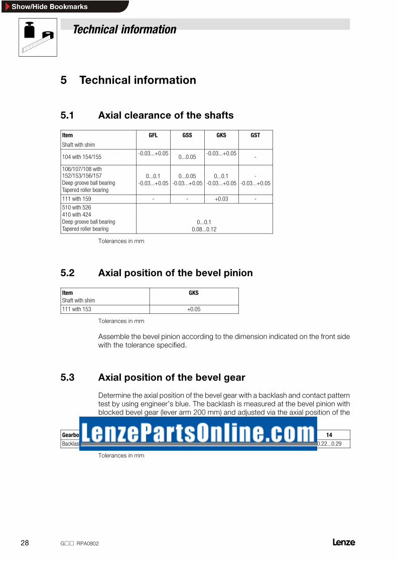
RKN ^ñá~ä ÅäÉ~ê~åÅÉ çÑ íÜÉ ëÜ~Ñíë
Item GFL GSS GKS GST
Shaft with shim
104 with 154/155-0.03...+0.05
0...0.05-0.03...+0.05
-
106/107/108 with152/153/156/157Deep groove ball bearingTapered roller bearing
0...0.1-0.03...+0.05
0...0.05-0.03...+0.05
0...0.1-0.03...+0.05
--0.03...+0.05
111 with 159 - - +0.03 -
510 with 526410 with 424Deep groove ball bearingTapered roller bearing
0...0.10.08...0.12
qçäÉê~åÅÉë áå ãã
RKO ^ñá~ä éçëáíáçå çÑ íÜÉ ÄÉîÉä éáåáçå
ItemShaft with shim
GKS
111 with 153 +0.05
qçäÉê~åÅÉë áå ãã
^ëëÉãÄäÉ íÜÉ ÄÉîÉä éáåáçå ~ÅÅçêÇáåÖ íç íÜÉ ÇáãÉåëáçå áåÇáÅ~íÉÇ çå íÜÉ Ñêçåí ëáÇÉïáíÜ íÜÉ íçäÉê~åÅÉ ëéÉÅáÑáÉÇK
RKP ^ñá~ä éçëáíáçå çÑ íÜÉ ÄÉîÉä ÖÉ~ê
aÉíÉêãáåÉ íÜÉ ~ñá~ä éçëáíáçå çÑ íÜÉ ÄÉîÉä ÖÉ~ê ïáíÜ ~ Ä~Åâä~ëÜ ~åÇ Åçåí~Åí é~ííÉêåíÉëí Äó ìëáåÖ ÉåÖáåÉÉêÛë ÄäìÉK qÜÉ Ä~Åâä~ëÜ áë ãÉ~ëìêÉÇ ~í íÜÉ ÄÉîÉä éáåáçå ïáíÜÄäçÅâÉÇ ÄÉîÉä ÖÉ~ê EäÉîÉê ~êã OMM ããF ~åÇ ~ÇàìëíÉÇ îá~ íÜÉ ~ñá~ä éçëáíáçå çÑ íÜÉÄÉîÉä ÖÉ~êK qÜÉ Åçåí~Åí é~ííÉêå ãìëí ÄÉ áå íÜÉ ãáÇÇäÉ çÑ íÜÉ ÖÉ~êK
Gearbox size 05 06 07 09 11 14Backlash 0.28...0.56 0.32...0.52 0.3...0.45 0.29...0.41 0.28...0.37 0.22...0.29
qçäÉê~åÅÉë áå ãã

Technical information
d om^MUMO OVjj
RKQ gçáåáåÖ ÑçêÅÉë Ñçê ÖÉ~êë
Item Gearbox size
04 05 06 07 09 11 14
Assembly forces in kN103
32 42 60 90 130 185 300111
32 42 60 90 130 185 300
105 55 80 115 165 265 --- ---
603 --- --- 32 42 60 90 130
RKR gçáåáåÖ éìëÜJáå éáåáçåë áíÉã OMNLSMO
NK `äÉ~å àçáåáåÖ ëìêÑ~ÅÉëK
OK låäó Ñçê éáåáçå ïáíÜ ÅìííáåÖ ÖêççîÉ áå íÜÉ ëÜ~åâWJ ^ééäó ~ íÜáå ä~óÉê çÑ içÅíáíÉ SMP çê tÉáÅçå ^kPMSMP çå íÜÉ ëÜ~åâK
PK c~ëíÉå íÜÉ éáåáçå ã~åì~ääó
QK nìáÅâäó éêÉëë áå ïáíÜ àçáåáåÖ ÑçêÅÉ ➡ í~ÄäÉ
RK `ÜÉÅâ àçáåáåÖ Çáëí~åÅÉ ➡ í~ÄäÉJ máåáçå ãìëí åçí ÄÉ äçÅ~íÉÇ çå íÜÉ ÄäçÅâ
Drive size Shank diameter[mm]
Joining force [kN] Joining distance [mm]
Shank with cut-ting groove with
adhesive
Shank withoutcutting groove
without adhesive min. max.
063-jj jjj-1A 7 7.5 11.5 0.8 1.4
071-jj jjj-1B 9 12.5 18.0 1.0 1.8
080-jj jjj-1C 11 17.0 26.5 1.1 2.0
090-jj jjj-1D 14 25.5 41.5 1.4 2.5
100-jj jjj-1E 18 39.0 63.5 1.8 3.2
112-jj jjj-1F 21 49.5 82.0 2.0 3.6
132-jj jjj-1G 26 78.5 125 2.4 4.3
160-jj jjj-1H / 2H 32 111 179 2.9 5.2
--- jjj-1K / 2K 38 --- 260 3.3 5.9
RKS oáåÖ áíÉãNOQLNOS
NK `äÉ~å ëÉ~ä ëìêÑ~ÅÉ
OK mêÉëë áå êáåÖ ïáíÜ ~å~ÉêçÄáÅ ~ÇÜÉëáîÉ EÉKÖK aÉäç jiROVUF

Spare parts order
30 d o m^M802jj
6 Spare parts order
6.1 Order form
all Gjj
Recipient: Lenze
Postal code/City: ________________________
Telefax no.: ________________________
Sender
Company ________________________________________Customer no. ________________________
Street / P.O. Box ________________________________________Order no. ________________________
Postal code / City ________________________________________Issued by ________________________
Delivery address ________________________________________Telephone ________________________
________________________________________Telefax ________________________
Invoice recipient* ________________________________________Date of delivery ________________________
*Please indicate if other than sender Date_____________ Signature ________________________
LENZE - type numberOrder number
Item Name Pieces Item Name Pieces101 Housing 120 Tapered roller bearing
102 Cover / housing 121 Tapered roller bearing
103 Gear 124 Ring
104 Pinion shaft / Worm shaft 125 Shaft seal
105 Gear / Worm gear 126 Ring
106 Hollow shaft / Shaft 127 Shaft seal
107 Shaft / Bushing 128 Shaft seal
108 Shaft 129 Shaft seal
109 Flange 130 Cover
110 Flange 131 Cover
111 Foot (only GFL) 132 Cover
111 Bevel gear set (only GKS) 135 Key
112 Shrink disk 136 Key
113 Bushing 139 Circlip
115 Tapered roller bearing 140 Circlip
116 Tapered roller bearing 141 Circlip
117 Deep groove ball bearing /Tapered roller bearing
142 Circlip
118 Deep groove ball bearing /Tapered roller bearing
143 Circlip
119 Deep groove ball bearing 144 Circlip

Spare parts order
d o m^M802 31jj
Item PiecesNameItemPiecesName145 Circlip 428 Cover
146 Circlip 440 Slinger150 Shim 501 Housing
151 Shim 510 Shaft
152 Shim 520 Deep groove ball bearing /Tapered roller bearing
153 Shim 521 Shaft seal
154 Shim 522 Circlip
155 Shim 523 Deep groove ball bearing /Tapered roller bearing
156 Shim 525 Circlip
157 Shim 526 Shim
158 Bushing 527 Oilslinger
159 Shim 528 Cover
160 Seal 530 Coupling
161 Seal 531 Gear rim
170 Allen screw 532 Key
171 Allen screw 540 Slinger
172 Allen screw 550 Hexagon head screw
173 Allen screw 551 Hexagon head nut
174 Allen screw 601 Housing attachment
201 Push-in pinion 602 Push-in pinion
202 Cover 603 Gear
203 Allen screw 604 Allen screw
204 Seal 605 Allen screw
205 Pin 610 Shaft
208 Filler plug 612 Cover
209 Filler plug 613 Allen screw
220 O-ring 614 Seal
221 Hexagon head screw 615 Pin
222 Hexagon head nut 618 Filler plug
301 Motor 620 Deep groove ball bearing
401 Housing 621 Shaft seal
410 Shaft 622 Circlip
420 Deep groove ball bearing /Tapered roller bearing
623 Deep groove ball bearing
421 Shaft seal 624 Shim
422 Circlip 625 Circlip
423 Deep groove ball bearing /Tapered roller bearing
626 Shim
424 Shim 630 Filler plug
425 Circlip 631 Filler plug
800 Lubricant

Manufacturer’s Certification
P2 d o m ̂MUMOjj
j~åìÑ~ÅíìêÉêÛë `ÉêíáÑáÅ~íáçåtÉ ÜÉêÉïáíÜ ÅÉêíáÑó íÜ~í íÜÉ ÄÉäçï äáëíÉÇ éêçÇìÅíë ~êÉ áåíÉåÇÉÇ Ñçê ~ëëÉãÄäó áåíç~ ã~ÅÜáåÉ çê Ñçê ~ëëÉãÄäó ïáíÜ çíÜÉê ÉäÉãÉåíë íç Ñçêã ~ ã~ÅÜáåÉK`çããáëëáçåáåÖ çÑ íÜÉ ã~ÅÜáåÉ áë éêçÜáÄáíÉÇ ÄÉÑçêÉ áí áë éêçîÉå íÜ~í áíÅçêêÉëéçåÇë íç íÜÉ b` êÉÖìä~íáçå VULPTLb`K
Gearboxes
Lenze Drive Systems GmbHPostfach 10 13 52D-31763 Hameln
Site: BösingfeldBreslauer Straße 3D-32699 ExtertalTelephone (05154) 82-0Telefax (05154) 82-15 75
mêçÇìÅíW qóéÉ W
içïJéêçÑáäÉ ÖÉ~êÄçñÉë ~åÇ ÖÉ~êÉÇ ãçíçêë dci
eÉäáÅ~ä ÖÉ~êÄçñÉë ~åÇ ÖÉ~êÉÇ ãçíçêë dpqI NOKS��
eÉäáÅ~ä ÄÉîÉä ÖÉ~êÄçñÉë ~åÇ ÖÉ~êÉÇ ãçíçêë dhpI NOKR��
_ÉîÉä ÖÉ~êÄçñÉë ~åÇ ÖÉ~êÉÇ ãçíçêë dho
eÉäáÅ~ä ïçêã ÖÉ~êÄçñÉë ~åÇ ÖÉ~êÉÇ ãçíçêë dppI ROKN��
s~êá~ÄäÉ ëéÉÉÇ ÄÉäí ÇêáîÉë ~åÇ ÖÉ~êÉÇ ãçíçêë d��Jh
NNKN��I NNKO��I NNKQ��
s~êá~ÄäÉ ëéÉÉÇ ÇêáîÉë ïáíÜLïáíÜçìí ÖÉ~êÄçñ d��Ja
NNKT��
pÜ~ÑíJãçìåíÉÇ ÖÉ~êÄçñÉë NOKQ��
tçêã ÖÉ~êÄçñÉë ~åÇ ÖÉ~êÉÇ ãçíçêë ROKP��I ROKQ��I ROKR��
^ééäáÉÇ ëí~åÇ~êÇë ~åÇ êÉÖìä~íáçåëW
bk OVO é~êí N
bk OVO é~êí O
e~ãÉäåI lÅíçÄÉê NUI OMMN
(i.V. Dr. Kiel)Head of R&D dept. gearboxes