![[#Mfgadvances] 9 warning signs](https://static.fdocuments.us/doc/165x107/55c5bb2ebb61eb89608b4790/mfgadvances-9-warning-signs.jpg)
MOTSAM Part I: Section 06 Permanent Warning Signs 1 signs contents jan 2010 i. section 6: permanent...
109
* . PERMANENT WARNING SIGNS SECTION 6 March 2011
Transcript of MOTSAM Part I: Section 06 Permanent Warning Signs 1 signs contents jan 2010 i. section 6: permanent...
*
.
PERMANENT WARNING SIGNS
.
SECTION 6
March 2011
Part 1 Signs CONTENTS Jan 2010
i
.
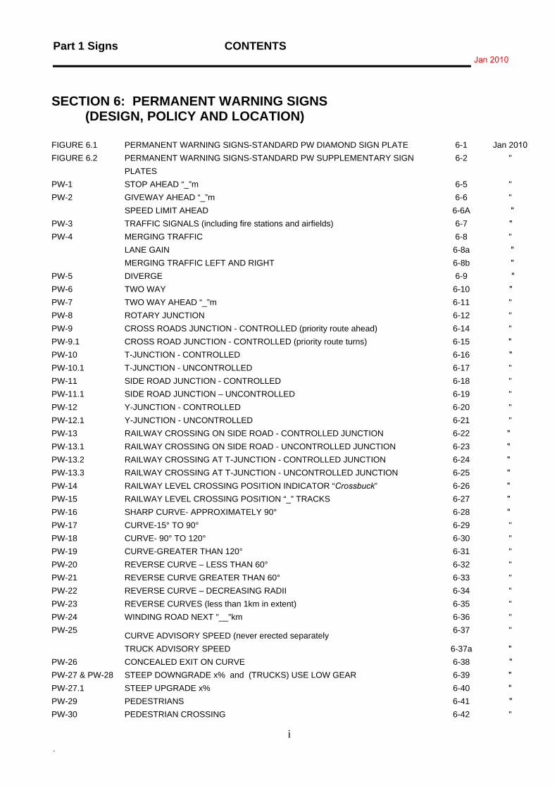
SECTION 6: PERMANENT WARNING SIGNS (DESIGN, POLICY AND LOCATION)
FIGURE 6.1 PERMANENT WARNING SIGNS-STANDARD PW DIAMOND SIGN PLATE 6-1 Jan 2010 FIGURE 6.2 PERMANENT WARNING SIGNS-STANDARD PW SUPPLEMENTARY SIGN
PLATES 6-2 "
PW-1 STOP AHEAD “_”m 6-5 " PW-2 GIVEWAY AHEAD “_”m 6-6 " SPEED LIMIT AHEAD 6-6A " PW-3 TRAFFIC SIGNALS (including fire stations and airfields) 6-7 " PW-4 MERGING TRAFFIC 6-8 " LANE GAIN 6-8a " MERGING TRAFFIC LEFT AND RIGHT 6-8b " PW-5 DIVERGE 6-9 " PW-6 TWO WAY 6-10 " PW-7 TWO WAY AHEAD “_”m 6-11 " PW-8 ROTARY JUNCTION 6-12 " PW-9 CROSS ROADS JUNCTION - CONTROLLED (priority route ahead) 6-14 " PW-9.1 CROSS ROAD JUNCTION - CONTROLLED (priority route turns) 6-15 " PW-10 T-JUNCTION - CONTROLLED 6-16 " PW-10.1 T-JUNCTION - UNCONTROLLED 6-17 " PW-11 SIDE ROAD JUNCTION - CONTROLLED 6-18 " PW-11.1 SIDE ROAD JUNCTION – UNCONTROLLED 6-19 " PW-12 Y-JUNCTION - CONTROLLED 6-20 " PW-12.1 Y-JUNCTION - UNCONTROLLED 6-21 " PW-13 RAILWAY CROSSING ON SIDE ROAD - CONTROLLED JUNCTION 6-22 " PW-13.1 RAILWAY CROSSING ON SIDE ROAD - UNCONTROLLED JUNCTION 6-23 "PW-13.2 RAILWAY CROSSING AT T-JUNCTION - CONTROLLED JUNCTION 6-24 " PW-13.3 RAILWAY CROSSING AT T-JUNCTION - UNCONTROLLED JUNCTION 6-25 " PW-14 RAILWAY LEVEL CROSSING POSITION INDICATOR “Crossbuck” 6-26 " PW-15 RAILWAY LEVEL CROSSING POSITION “_” TRACKS 6-27 " PW-16 SHARP CURVE- APPROXIMATELY 90° 6-28 " PW-17 CURVE-15° TO 90° 6-29 " PW-18 CURVE- 90° TO 120° 6-30 " PW-19 CURVE-GREATER THAN 120° 6-31 " PW-20 REVERSE CURVE – LESS THAN 60° 6-32 " PW-21 REVERSE CURVE GREATER THAN 60° 6-33 " PW-22 REVERSE CURVE – DECREASING RADII 6-34 " PW-23 REVERSE CURVES (less than 1km in extent) 6-35 " PW-24 WINDING ROAD NEXT "__"km 6-36 " PW-25
CURVE ADVISORY SPEED (never erected separately 6-37 "
TRUCK ADVISORY SPEED 6-37a " PW-26 CONCEALED EXIT ON CURVE 6-38 " PW-27 & PW-28 STEEP DOWNGRADE x% and (TRUCKS) USE LOW GEAR 6-39 " PW-27.1 STEEP UPGRADE x% 6-40 " PW-29 PEDESTRIANS 6-41 " PW-30 PEDESTRIAN CROSSING 6-42 "
CONTENTS Part 1 Signs Mar 2011
ii .
PW-31 CHILDREN 6-43 Jan 2010 PW-32 SCHOOL 6-44 " PW-33 SCHOOL CROSSING 6-45 " PW-34 SCHOOL BUS ROUTE (TURNS) 6-46 " PW-35 CYCLISTS 6-47 Mar 2011 PW-36 HORSES 6-48 Jan 2010 WILD HORSES 6-49 " PW-37 STOCK - PERMANENT (CATTLE) 6-50 " PW-37.1 STOCK - PERMANENT (SHEEP) 6-50 " RAILWAY TRACKS – CYCLISTS TAKE CARE 6-51 " PW-38 SUDDEN DIP 6-52 " PW-39 HUMP 6-53 " PW-40 UNEVEN SURFACE 6-54 " PW-41 SLIPPERY SURFACE (never erected separately) 6-55 " PW-41.1 SLIPPERY SURFACE - WHEN FROSTY 6-56 " PW-41.2 SLIPPERY SURFACE - WHEN WET 6-57 " PW-41.3 GRAVEL SURFACE (end of seal situations) 6-58 " PW-42 SLIPS / FALLING DEBRIS 6-59 " PW-43 ROAD NARROWS (left or right side narrowing ) 6-60 " PW-43.1 ROAD NARROWS (both sides narrowing) 6-60 " PW-43.2 ROAD NARROWS AHEAD “_”m 6-62 " PW-44 NARROW BRIDGE 6-63 " PW-44.1 NARROW BRIDGE - CAUTION WIDE VEHICLES 6-64 " PW-45 LOW OVERHEAD CLEARANCE - ADVANCE WARNING 6-65 " PW-46 LOW OVERHEAD CLEARANCE INDICATION ON STRUCTURE OR TUNNEL 6-66 " FIGURE 6.3 SIGNING AND SUPPLEMENTARY MARKINGS ON STRUCTURE OR TUNNEL
WITH VARYING SOFFIT HEIGHT (single lane roadway) 6.67 "
PW-47 OVERHEAD ELECTRIC CABLE (never erected separately) 6-68 " PW-48 WIND GUSTS 6-69 " PW-49 FIRE STATION 6-70 " PW-50 TRUCKS 6-71 " FORK LIFTS 6-71a " PW-51 AIRCRAFT 6-72 " HELICOPTERS 6-72a " PW-52 TUNNEL 6-73 " PW-53 OTHER HAZARDS - BASIC DESIGN (never erected separately) 6-74 " PW-54 OTHER HAZARDS – FORD 6-75 " PW-55 OTHER HAZARD - CATTLE SHOP 6-76 " PW-56 OTHER HAZARD GATE 6-77 " PW-57 RAILWAY LEVEL CROSSING ("Steam train") 6-78 " PW-57.1 RAILWAY LEVEL CROSSING AHEAD "__"m 6-80 " PW-58 RAILWAY LEVEL CROSSING - FLASHING LIGHT SIGNALS AHEAD 6-81 " PW-59 RAILWAY LEVEL CROSSING - "LOOK FOR TRAINS" 6-83 " PW-60 RAILWAY LEVEL CROSSING - SUBSTANTIALLY AT A RIGHT ANGLE 6-84 " PW-60.1 RAILWAY LEVEL CROSSING - AT AN OBLIQUE ANGLE 6-84 " PW-60.2 RAILWAY LEVEL CROSSING - AT AN OBLIQUE ANGLE 6-84 " PW-61 RAILWAY LEVEL CROSSING - INTERMEDIATE ADVANCE WARNING 6-86 "
Part 1 Signs CONTENTS Jan 2010
iii
.
PW-62 RAILWAY LEVEL CROSSING ON A SIDE ROAD – INTERMEDIATE ADVANCE WARNING
6-87 Jan 2010
PW-63 TRAM 6-88 " PW-64 ADVANCE WARNING TRAFFIC SIGNIALS 6-89 " PW-65 BELISHA BEACON DISK 6-91 " PW-66 CHEVRON BOARD - HORIZONTAL CURVE 6-92 " PW-67 CHEVRON CURVE INDICATOR 6-94 " NB: CURVE WARNING SIGNS - NEW HIERARCHY PW-68 CHEVRON BOARD - ‘T’ INTERSECTION
6-95a May 2008
PW-69 CHEVRON BOARD - ROUNDABOUTS 6-96 Jan 2010 6-96 " 6-97 Nov 2007
WOODEN SIGHT RAILS
Part 1 Signs PERMANENT WARNING SIGNSJanuary 2010*
6 - 1
PERMANENT WARNING SIGNSSTANDARD PW DIAMOND SIGN PLATE FIG. 6.1
Sign Size a b c d600 x 600 800 10 25 40
750 x 750 750 10 30 50
900 x 900 900 10 35 60
1200 x 1200 1200 10 50 80
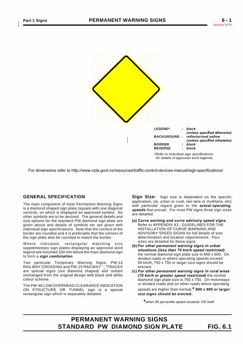
GENERAL SPECIFICATIONThe main component of most Permanent Warning Signsis a diamond shaped sign plate (square with one diagonalvertical), on which is displayed an approved symbol. Noother symbols are to be devised. The general details andsize options for the standard PW diamond sign plate aregiven above and details of symbols etc are given withindividual sign specifications. Note that the corners of theborder are rounded and it is preferable that the corners ofthe sign plate also be rounded to match the border.
Where ind icated, rec tangu lar match ing s izesupplementary sign plates displaying an approved wordlegend are mounted 100 mm below the main diamond signto form a sign combination.
Two particular Temporary Warning Signs, PW-14RAILWAY CROSSING and PW-15 RAILWAY "_"TRACKSare special signs (not diamond shaped) and remainunchanged from the original design with black and whitecolour scheme.
The PW-46 LOW OVERHEAD CLEARANCE INDICATIONON STRUCTURE OR TUNNEL sign is a specialrectangular sign which is separately detailed.
LEGEND* : black(unless specified otherwise)
BACKGROUND : reflectorised yellow (unless specified otherwise)*
BORDER : blackREVERSE : black
*Refer to individual sign specifications for details of approved word legends.
Sign Size: Sign size is dependent on the specificapplication, (ie, urban or rural, two lane or multilane, etc)with particular regard given to the actual operatingspeeds that prevail. For most PW signs three sign sizesare detailed.
(a) Curve warning and curve advisory speed signs. Refer to APPENDIX A3 - GUIDELINES FOR THE INSTALLATION OF CURVE WARNING AND ADVISORY SPEED SIGNS for full details of sizedetermination and location requirements. Four sizes are detailed for these signs.
(b) For other permanent warning signs in urbansituations (less than 70 km/h speed restricted) the normal diamond sign plate size is 600 x 600. Ondivided roads or where operating speeds exceed50 km/h, 750 x 750 or larger size signs should beerected.
(c) For other permanent warning signs in rural areas(70 km/h or greater speed restricted) the normaldiamond sign plate size is 750 x 750. On motorwaysor divided roads and on other roads where operatingspeeds are higher than normal,* 900 x 900 or largersize signs should be erected.
*when 85 percentile speed exceeds 100 km/h
For dimensions refer to http://www.nzta.govt.nz/resources/traffic-control-devices-manual/sign-specifications/
PERMANENT WARNING SIGNS Part 1 SignsJanuary 20106 - 2
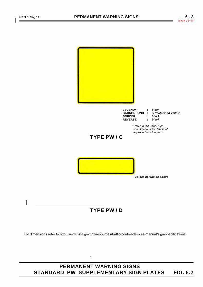
PERMANENT WARNING SIGNSFIG. 6.2 STANDARD PW SUPPLEMENTARY SIGN PLATES
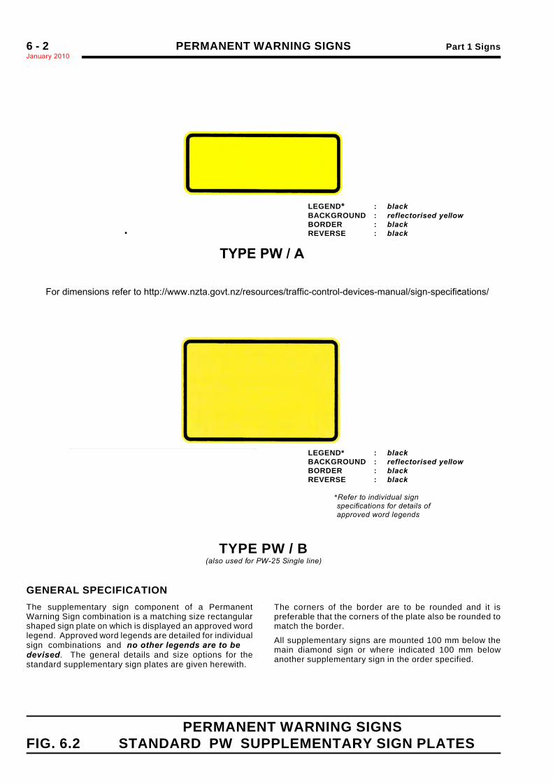
LEGEND* : blackBACKGROUND : reflectorised yellowBORDER : blackREVERSE : black
LEGEND* : blackBACKGROUND : reflectorised yellowBORDER : blackREVERSE : black
*Refer to individual sign specifications for details of approved word legends
Size ofMatching PWDiamond Sign
PW/A Supplementary Plate
a b c d e600 × 600 600 250 10 25 40750 ×750 750 300 10 50900 × 900 900 350 10 35 60
Size ofMatching PWDiamond Sign
PW/B Supplementary Plate
a b c d e600 × 600 600 400 10 25 40750 × 750 750 500 10 30 50900 × 900 900 600 10 35 60
1200 × 1200 1200 800 10 40 70
.
TYPE PW / B(also used for PW-25 Single line)
GENERAL SPECIFICATIONThe supplementary sign component of a PermanentWarning Sign combination is a matching size rectangularshaped sign plate on which is displayed an approved wordlegend. Approved word legends are detailed for individualsign combinations and no other legends are to bedevised. The general details and size options for thestandard supplementary sign plates are given herewith.
The corners of the border are to be rounded and it ispreferable that the corners of the plate also be rounded tomatch the border.
All supplementary signs are mounted 100 mm below themain diamond sign or where indicated 100 mm belowanother supplementary sign in the order specified.
.
TYPE PW / A
For dimensions refer to http://www.nzta.govt.nz/resources/traffic-control-devices-manual/sign-specifications/
Part 1 Signs PERMANENT WARNING SIGNSJanuary 2010*
6 - 3
PERMANENT WARNING SIGNSSTANDARD PW SUPPLEMENTARY SIGN PLATES FIG. 6.2
LEGEND* : blackBACKGROUND : reflectorised yellowBORDER : blackREVERSE : black
*Refer to individual sign specifications for details of approved word legends
Colour details as above
TYPE PW / C
TYPE PW / D
.
Size ofMatching PWDiamond Sign
PW/A Supplementary Plate
a b c d e600 × 600 600 600 10 25 40750 ×750 750 750 10 30 50900 × 900 900 900 10 35 60
Size ofMatching PWDiamond Sign
PW/B Supplementary Plate
a b c d e600 × 600 600 250 10 25 40750 × 750 750 300 10 30 50900 × 900 900 350 10 35 60
1200 × 1200 1200 500 10 40* 70*
For dimensions refer to http://www.nzta.govt.nz/resources/traffic-control-devices-manual/sign-specifications/
PERMANENT WARNING SIGNS Part 1 SignsJanuary 20106 - 4
(This page is intentionally blank)*
Part 1 Signs PERMANENT WARNING SIGNSJanuary 2010*
6 - 5
STOP AHEAD " " m P W - 1
.
.
.
.
.
Diamond Sign "STOP" Symbol Matching Supplementary Sign - (Type PW/A)
* Modified E Refer to AppendixA1
Sign Size a b c d e f g Symbol "m"(loop height)* Distance Numerals
600 x 600 400 165 15 600 250 96* 50* 70 ** 100 D
750 x 750 500 2007 20 750 300 107* 65* 85 ** 125 D
900 x 900 600 248 25 900 350 144* 75* 100 ** 150 D
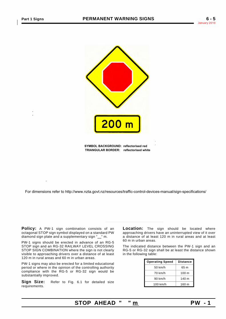
Policy: A PW-1 sign combination consists of anoctagonal STOP sign symbol displayed on a standard PWdiamond sign plate and a supplementary sign " " m.
PW-1 signs should be erected in advance of an RG-5STOP sign and an RG-32 RAILWAY LEVEL CROSSINGSTOP SIGN COMBINATION where the sign is not clearlyvisible to approaching drivers over a distance of at least120 m in rural areas and 60 m in urban areas.
PW-1 signs may also be erected for a limited educationalperiod or where in the opinion of the controlling authoritycompliance with the RG-5 or RG-32 sign would besubstantially improved.
Sign Size: Refer to Fig. 6.1 for detailed sizerequirements.
Location: The sign should be located whereapproaching drivers have an uninterrupted view of it overa distance of at least 120 m in rural areas and at least60 m in urban areas.
The indicated distance between the PW-1 sign and anRG-5 or RG-32 sign shall be at least the distance shownin the following table:
Operating Speed Distance
50 km/h 65 m
70 km/h 100 m
90 km/h 140 m
100 km/h 160 m
SYMBOL BACKGROUND: reflectorised red TRIANGULAR BORDER: reflectorised white
For dimensions refer to http://www.nzta.govt.nz/resources/traffic-control-devices-manual/sign-specifications/
PERMANENT WARNING SIGNS Part 1 SignsJanuary 20106 - 6
PW - 2 GIVE WAY AHEAD " " m
.
.
.
Diamond Sign "GIVE WAY " Symbol Matching Supplementary Sign - (Type PW/A)
Sign Size a b c d e f g h j Symbol "m" DistanceNumerals
600 x 600 500 50 10 30 100 600 250 96 50 90 Mod.E 100 D
750 x 750 625 65 15 40 125 750 300 123 65 115 Mod.E 125 D
900 x 900 750 75 20 45 150 900 350 144 75 135 Mod.E 150 D
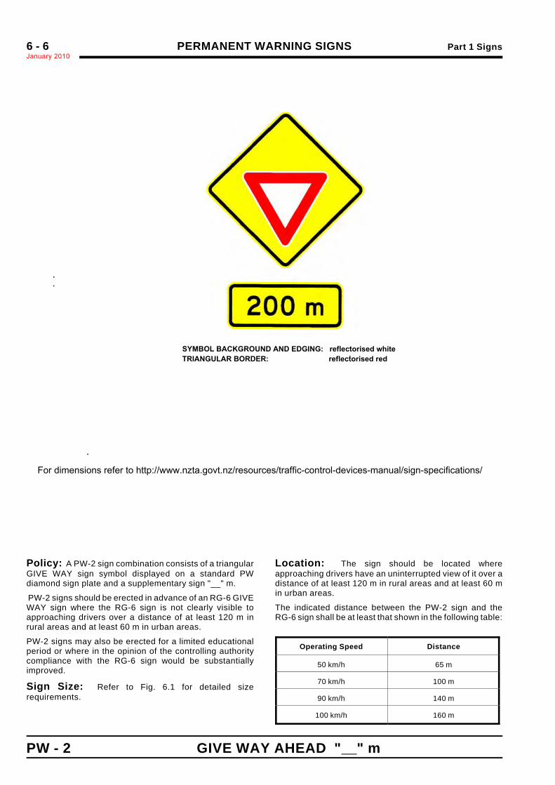
Policy: A PW-2 sign combination consists of a triangularGIVE WAY sign symbol displayed on a standard PWdiamond sign plate and a supplementary sign "__" m.
PW-2 signs should be erected in advance of an RG-6 GIVEWAY sign where the RG-6 sign is not clearly visible toapproaching drivers over a distance of at least 120 m inrural areas and at least 60 m in urban areas.
PW-2 signs may also be erected for a limited educationalperiod or where in the opinion of the controlling authoritycompliance with the RG-6 sign would be substantiallyimproved.
Sign Size: Refer to Fig. 6.1 for detailed sizerequirements.
Location: The sign should be located whereapproaching drivers have an uninterrupted view of it over adistance of at least 120 m in rural areas and at least 60 min urban areas.
The indicated distance between the PW-2 sign and theRG-6 sign shall be at least that shown in the following table:
Operating Speed Distance
50 km/h 65 m
70 km/h 100 m
90 km/h 140 m
100 km/h 160 m
.
.
For dimensions refer to http://www.nzta.govt.nz/resources/traffic-control-devices-manual/sign-specifications/
SYMBOL BACKGROUND AND EDGING: reflectorised whiteTRIANGULAR BORDER: reflectorised red
PERMANENT WARNING SIGNS Part 1 SignsNovember 2010
6 - 6a
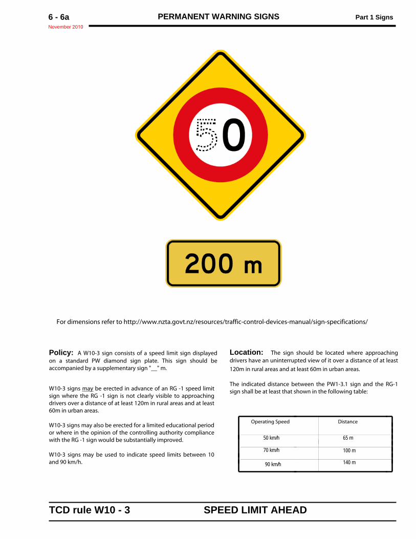
Policy: A W10-3 sign consists of a speed limit sign displayedon a standard PW diamond sign plate. This sign should beaccompanied by a supplementary sign "__" m.
W10-3 signs may be erected in advance of an RG -1 speed limitsign where the RG -1 sign is not clearly visible to approachingdrivers over a distance of at least 120m in rural areas and at least60m in urban areas.
W10-3 signs may also be erected for a limited educational periodor where in the opinion of the controlling authority compliancewith the RG -1 sign would be substantially improved.
W10-3 signs may be used to indicate speed limits between 10and 90 km/h.
Location: The sign should be located where approachingdrivers have an uninterrupted view of it over a distance of at least120m in rural areas and at least 60m in urban areas.
The indicated distance between the PW1-3.1 sign and the RG-1sign shall be at least that shown in the following table:
For dimensions refer to http://www.nzta.govt.nz/resources/traffic-control-devices-manual/sign-specifications/
TCD rule W10 - 3 SPEED LIMIT AHEAD
Operating Speed Distance
50 km/h 65 m
70 km/h 100 m
90 km/h 140 m
Part 1 Signs PERMANENT WARNING SIGNSJanuary 2010*
6 - 7
TRAFFIC SIGNALS (incl. tunnels, fire stations, airfields) PW - 3
.
.
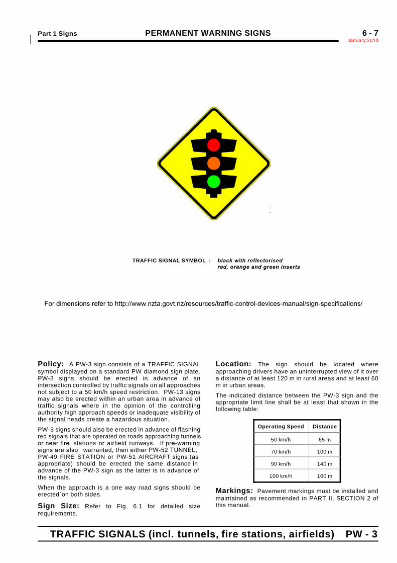
TRAFFIC SIGNAL SYMBOL : black with reflectorisedred, orange and green inserts
Sign Size a b c d e f g h j k l m n o p q r s t600 x 600 130 115 115 490 50 30 90 20 95 110 45 25 40 100 30 80 10 52 48
750 x 750 165 140 145 615 70 35 115 25 120* 140 55 30 50 125 40 100 15 65 60
900 x 900 200 165 175 740 90 40 140 30 145* 170 65 35 65 150 45 120 20 78 72
Policy: A PW-3 sign consists of a TRAFFIC SIGNALsymbol displayed on a standard PW diamond sign plate.PW-3 signs should be erected in advance of anintersection controlled by traffic signals on all approachesnot subject to a 50 km/h speed restriction. PW-13 signsmay also be erected within an urban area in advance oftraffic signals where in the opinion of the controllingauthority high approach speeds or inadequate visibility ofthe signal heads create a hazardous situation.
PW-3 signs should also be erected in advance of flashingred signals that are operated on roads approaching tunnelsor near fire stations or airfield runways. If pre-warning signs are also warranted, then either PW-52 TUNNEL,PW-49 FIRE STATION or PW-51 AIRCRAFT signs (asappropriate) should be erected the same distance inadvance of the PW-3 sign as the latter is in advance ofthe signals.
When the approach is a one way road signs should beerected`on both sides.
Sign Size: Refer to Fig. 6.1 for detailed sizerequirements.
Location: The sign should be located whereapproaching drivers have an uninterrupted view of it overa distance of at least 120 m in rural areas and at least 60m in urban areas.
The indicated distance between the PW-3 sign and theappropriate limit line shall be at least that shown in thefollowing table:
Operating Speed Distance
50 km/h 65 m
70 km/h 100 m
90 km/h 140 m
100 km/h 160 m
Markings: Pavement markings must be installed andmaintained as recommended in PART II, SECTION 2 ofthis manual.
For dimensions refer to http://www.nzta.govt.nz/resources/traffic-control-devices-manual/sign-specifications/
StanleyC
Line
StanleyC
Line
StanleyC
Line
PERMANENT WARNING SIGNS Part 1 SignsJanuary 20106 - 8
PW - 4 MERGING TRAFFIC
.
.
Sign Size a b c d e f600 × 600 140 100 160 90 260 300750 ×750 175 125 200 110 325 375900 × 900 210 150 240 135 390 450
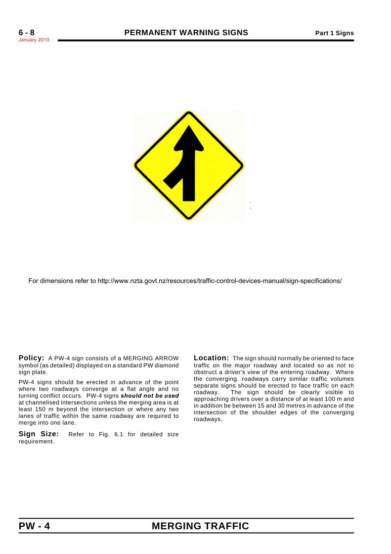
Policy: A PW-4 sign consists of a MERGING ARROWsymbol (as detailed) displayed on a standard PW diamondsign plate.
PW-4 signs should be erected in advance of the pointwhere two roadways converge at a flat angle and noturning conflict occurs. PW-4 signs should not be usedat channelised intersections unless the merging area is atleast 150 m beyond the intersection or where any twolanes of traffic within the same roadway are required tomerge into one lane.
Sign Size: Refer to Fig. 6.1 for detailed sizerequirement.
Location: The sign should normally be oriented to facetraffic on the major roadway and located so as not toobstruct a driver's view of the entering roadway. Wherethe converging. roadways carry similar traffic volumesseparate signs should be erected to face traffic on eachroadway. The sign should be clearly visible toapproaching drivers over a distance of at least 100 m andin addition be between 15 and 30 metres in advance of theintersection of the shoulder edges of the convergingroadways.
ARROW : Type ANOTE: RH version is mirror image of above For dimensions refer to http://www.nzta.govt.nz/resources/traffic-control-devices-manual/sign-specifications/
PERMANENT WARNING SIGNS Part 1 Signs
November 2010
6 - 8a
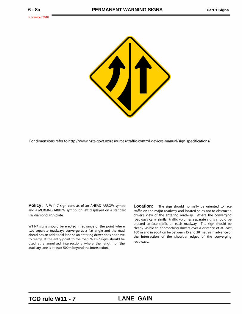
Policy: A W11-7 sign consists of an AHEAD ARROW symboland a MERGING ARROW symbol on left displayed on a standardPW diamond sign plate.
W11-7 signs should be erected in advance of the point wheretwo separate roadways converge at a flat angle and the roadahead has an additional lane so an entering driver does not haveto merge at the entry point to the road. W11-7 signs should beused at channelised intersections where the length of theauxiliary lane is at least 500m beyond the intersection.
Location: The sign should normally be oriented to facetraffic on the major roadway and located so as not to obstruct adriver's view of the entering roadway. Where the convergingroadways carry similar traffic volumes separate signs should beerected to face traffic on each roadway. The sign should beclearly visible to approaching drivers over a distance of at least100 m and in addition be between 15 and 30 metres in advance ofthe intersection of the shoulder edges of the convergingroadways.
For dimensions refer to http://www.nzta.govt.nz/resources/traffic-control-devices-manual/sign-specifications/
TCD rule W11 - 7 LANE GAIN
PERMANENT WARNING SIGNS Part 1 SignsNovember 2010
6 - 8b
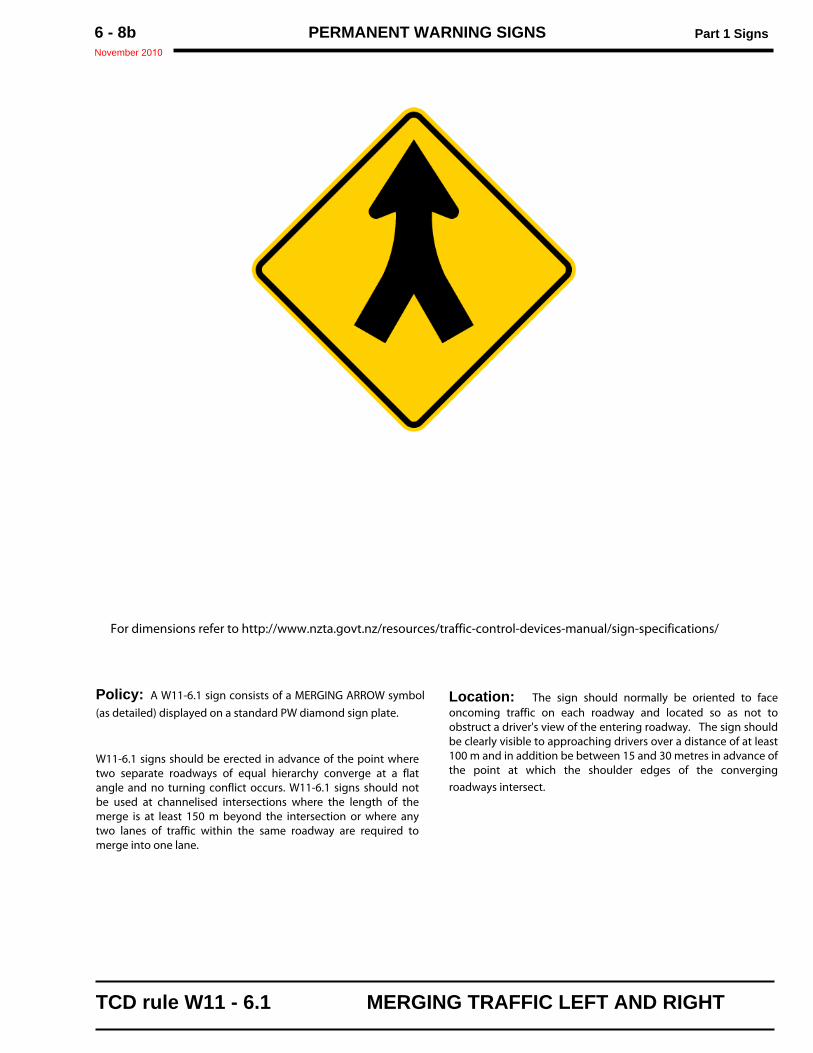
Policy: A W11-6.1 sign consists of a MERGING ARROW symbol(as detailed) displayed on a standard PW diamond sign plate.
W11-6.1 signs should be erected in advance of the point wheretwo separate roadways of equal hierarchy converge at a flatangle and no turning conflict occurs. W11-6.1 signs should notbe used at channelised intersections where the length of themerge is at least 150 m beyond the intersection or where anytwo lanes of traffic within the same roadway are required tomerge into one lane.
Location: The sign should normally be oriented to faceoncoming traffic on each roadway and located so as not toobstruct a driver's view of the entering roadway. The sign shouldbe clearly visible to approaching drivers over a distance of at least100 m and in addition be between 15 and 30 metres in advance ofthe point at which the shoulder edges of the convergingroadways intersect.
For dimensions refer to http://www.nzta.govt.nz/resources/traffic-control-devices-manual/sign-specifications/
TCD rule W11 - 6.1 MERGING TRAFFIC LEFT AND RIGHT
Part 1 Signs PERMANENT WARNING SIGNSJanuary 2010
6 - 9
DIVERGE PW - 5
.
.
Sign Size a b c d e600 × 600 100 200 240 80 300750 ×750 125 250 300 100 375900 × 900 150 300 360 120 450
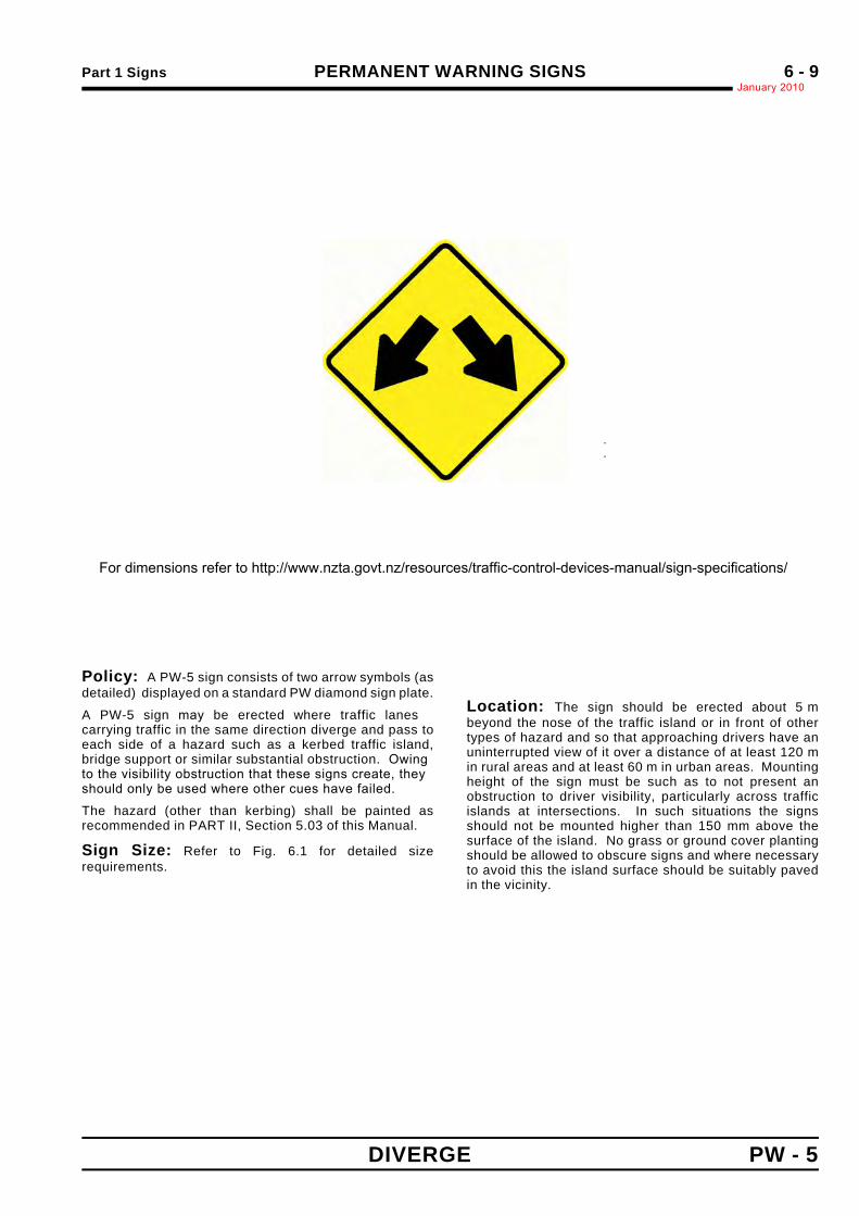
Policy: A PW-5 sign consists of two arrow symbols (asdetailed) displayed on a standard PW diamond sign plate.
A PW-5 sign may be erected where traffic lanescarrying traffic in the same direction diverge and pass toeach side of a hazard such as a kerbed traffic island,bridge support or similar substantial obstruction. Owingto the visibility obstruction that these signs create, theyshould only be used where other cues have failed.
The hazard (other than kerbing) shall be painted asrecommended in PART II, Section 5.03 of this Manual.
Sign Size: Refer to Fig. 6.1 for detailed sizerequirements.
Location: The sign should be erected about 5 mbeyond the nose of the traffic island or in front of othertypes of hazard and so that approaching drivers have anuninterrupted view of it over a distance of at least 120 min rural areas and at least 60 m in urban areas. Mountingheight of the sign must be such as to not present anobstruction to driver visibility, particularly across trafficislands at intersections. In such situations the signsshould not be mounted higher than 150 mm above thesurface of the island. No grass or ground cover plantingshould be allowed to obscure signs and where necessaryto avoid this the island surface should be suitably pavedin the vicinity.
ARROW : Type AFor dimensions refer to http://www.nzta.govt.nz/resources/traffic-control-devices-manual/sign-specifications/
PERMANENT WARNING SIGNS Part 1 SignsJanuary 20106 - 10
PW - 6 TWO WAY
.
.
Sign Size a b c d600 × 600 220 230 80 50750 ×750 275 290 100 60900 × 900 330 350 120 75
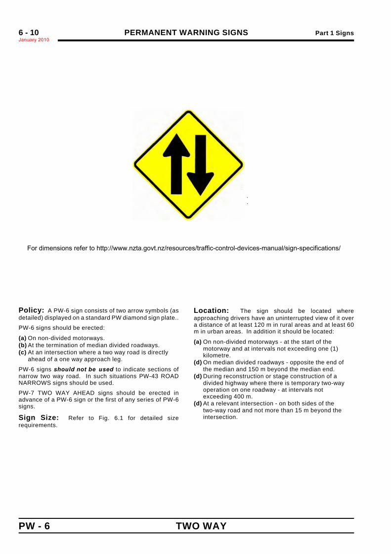
Policy: A PW-6 sign consists of two arrow symbols (asdetailed) displayed on a standard PW diamond sign plate..
PW-6 signs should be erected:
(a) On non-divided motorways.(b) At the termination of median divided roadways.(c) At an intersection where a two way road is directly
ahead of a one way approach leg.
PW-6 signs should not be used to indicate sections ofnarrow two way road. In such situations PW-43 ROADNARROWS signs should be used.
PW-7 TWO WAY AHEAD signs should be erected inadvance of a PW-6 sign or the first of any series of PW-6signs.
Sign Size: Refer to Fig. 6.1 for detailed sizerequirements.
Location: The sign should be located whereapproaching drivers have an uninterrupted view of it overa distance of at least 120 m in rural areas and at least 60m in urban areas. In addition it should be located:
(a) On non-divided motorways - at the start of themotorway and at intervals not exceeding one (1)kilometre.
(d) On median divided roadways - opposite the end ofthe median and 150 m beyond the median end.
(d) During reconstruction or stage construction of adivided highway where there is temporary two-wayoperation on one roadway - at intervals notexceeding 400 m.
(d) At a relevant intersection - on both sides of thetwo-way road and not more than 15 m beyond theintersection.
ARROW : Type AFor dimensions refer to http://www.nzta.govt.nz/resources/traffic-control-devices-manual/sign-specifications/
Part 1 Signs PERMANENT WARNING SIGNSJanuary 2010*
6 - 11
TWO WAY AHEAD "__" m PW - 7
.
.
Size ofPW-6 Sign
Matching Suppl
a b c d Symbol"m"
DistanceNumerals
600 × 600 600 250 96* 50* 90 Mod.E* 100 D
750 ×750 750 300 107* 65* 100 Mod.E* 125 D
900 × 900 900 350 144* 75* 135 Mod.E* 150 D
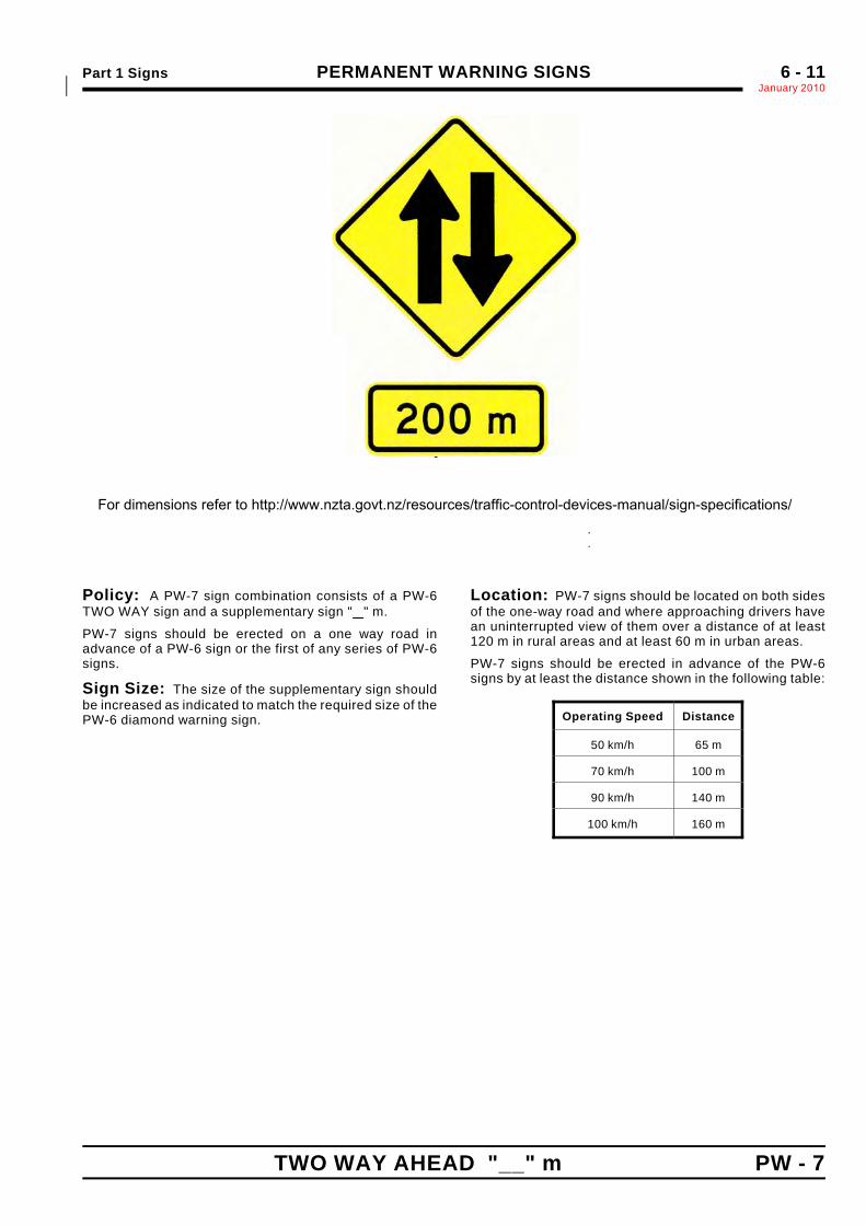
Policy: A PW-7 sign combination consists of a PW-6TWO WAY sign and a supplementary sign " " m.
PW-7 signs should be erected on a one way road inadvance of a PW-6 sign or the first of any series of PW-6signs.
Sign Size: The size of the supplementary sign shouldbe increased as indicated to match the required size of thePW-6 diamond warning sign.
Location: PW-7 signs should be located on both sidesof the one-way road and where approaching drivers havean uninterrupted view of them over a distance of at least120 m in rural areas and at least 60 m in urban areas.
PW-7 signs should be erected in advance of the PW-6signs by at least the distance shown in the following table:
Operating Speed Distance
50 km/h 65 m
70 km/h 100 m
90 km/h 140 m
100 km/h 160 m
.
For dimensions refer to http://www.nzta.govt.nz/resources/traffic-control-devices-manual/sign-specifications/

PERMANENT WARNING SIGNS Part 1 SignsJanuary 2010*6 - 12
PW - 8 ROTARY JUNCTION
.
.
Sign Size a b c d e600 × 600 100 120 160 60 10750 ×750 125 155 200 75 13900 × 900 150 185 240 90 15
Policy: A PW-8 sign consists of three curved arrowsymbols (as detailed) displayed on a standard PWdiamond sign plate.
PW-8 signs should be erected in advance of rotaryjunctions were traffic is required to circulate around acentral island and an AD-5 type sign is not installed.
Where an RG-6.1 ROUNDABOUT GIVE WAY sign at the*entry to a rotary junction is not clearly visible to*approaching drivers, over a distance of at least 120 m in*rural areas and at least 60 m in urban areas, a*supplementary sign " " m should added below the PW-8*sign, to form a sign combination similar to the PW-2 GIVE*WAY AHEAD " " sign.*
Sign Size: Refer to Fig. 6.1 for detailed sizerequirements.
Location: The sign should be located whereapproaching drivers have an uninterrupted view of it overa distance of at least 120 m in rural areas and at least 60m in urban areas.
PW-7 signs should be erected in advance of the PW-6signs by at least the distance shown in the following table:
Operating Speed Distance
50 km/h 65 m
70 km/h 100 m
90 km/h 140 m
100 km/h 160 m
ARROW : Type A (Modified with non-standard stroke width)For dimensions refer to http://www.nzta.govt.nz/resources/traffic-control-devices-manual/sign-specifications/
Part 1 Signs PERMANENT WARNING SIGNSJanuary 2010
6 - 13
(This page is intentionally blank)*
PERMANENT WARNING SIGNS Part 1 SignsJanuary 2010*6 - 14
CROSS ROADS JUNCTION – CONTROLLEDPW - 9 (priority route ahead)
.
.
Sign Size a b c d e600 × 600 100 150 270 60 320750 ×750 125 190 340 75 400900 × 900 150 375 405 90 480
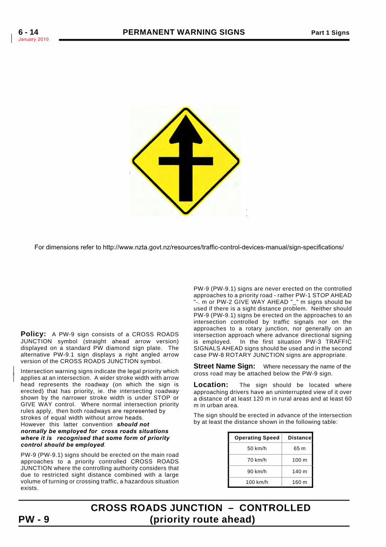
Policy: A PW-9 sign consists of a CROSS ROADSJUNCTION symbol (straight ahead arrow version)displayed on a standard PW diamond sign plate. Thealternative PW-9.1 sign displays a right angled arrowversion of the CROSS ROADS JUNCTION symbol.
Intersection warning signs indicate the legal priority which*applies at an intersection. A wider stroke width with arrow*head represents the roadway (on which the sign iserected) that has priority, ie. the intersecting roadwayshown by the narrower stroke width is under STOP orGIVE WAY control. Where normal intersection priorityrules apply, then both roadways are represented bystrokes of equal width without arrow heads.However this latter convention should notnormally be employed for cross roads situationswhere it is recognised that some form of prioritycontrol should be employed.
PW-9 (PW-9.1) signs should be erected on the main roadapproaches to a priority controlled CROSS ROADSJUNCTION where the controlling authority considers thatdue to restricted sight distance combined with a largevolume of turning or crossing traffic, a hazardous situationexists.
PW-9 (PW-9.1) signs are never erected on the controlledapproaches to a priority road - rather PW-1 STOP AHEAD"-. m or PW-2 GIVE WAY AHEAD "_" m signs should beused if there is a sight distance problem. Neither shouldPW-9 (PW-9.1) signs be erected on the approaches to anintersection controlled by traffic signals nor on theapproaches to a rotary junction, nor generally on anintersection approach where advance directional signingis employed. In the first situation PW-3 TRAFFICSIGNALS AHEAD signs should be used and in the secondcase PW-8 ROTARY JUNCTION signs are appropriate.
Street Name Sign: Where necessary the name of the cross road may be attached below the PW-9 sign.
Location: The sign should be located whereapproaching drivers have an uninterrupted view of it overa distance of at least 120 m in rural areas and at least 60m in urban area.
The sign should be erected in advance of the intersectionby at least the distance shown in the following table:
Operating Speed Distance
50 km/h 65 m
70 km/h 100 m
90 km/h 140 m
100 km/h 160 m
.For dimensions refer to http://www.nzta.govt.nz/resources/traffic-control-devices-manual/sign-specifications/
PERMANENT WARNING SIGNS Part 1 SignsJanuary 2010
6 - 15
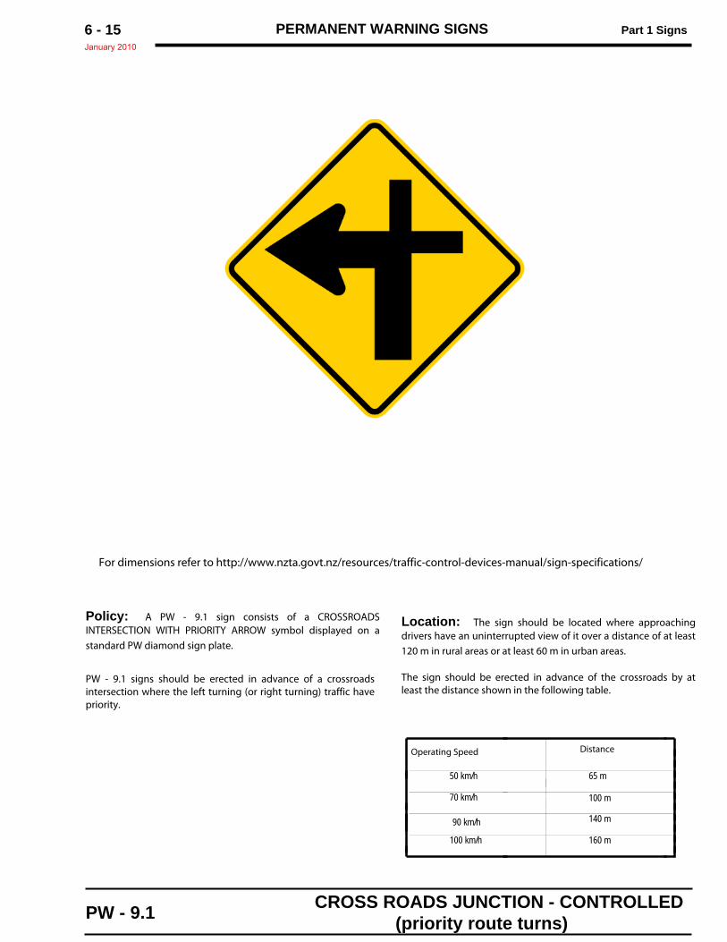
Policy: A PW - 9.1 sign consists of a CROSSROADSINTERSECTION WITH PRIORITY ARROW symbol displayed on astandard PW diamond sign plate.
PW - 9.1 signs should be erected in advance of a crossroadsintersection where the left turning (or right turning) traffic havepriority.
Location: The sign should be located where approachingdrivers have an uninterrupted view of it over a distance of at least120 m in rural areas or at least 60 m in urban areas.
The sign should be erected in advance of the crossroads by atleast the distance shown in the following table.
For dimensions refer to http://www.nzta.govt.nz/resources/traffic-control-devices-manual/sign-specifications/
PW - 9.1 CROSS ROADS JUNCTION - CONTROLLED(priority route turns)
Operating Speed Distance
50 km/h 65 m
70 km/h 100 m
90 km/h 140 m
160 m100 km/h
PERMANENT WARNING SIGNS Part 1 SignsJanuary 2010*6 - 16
PW - 10 T - JUNCTION – CONTROLLED
.
.
Sign Size a b c d e f600 × 600 100 250 40 60 240 300750 ×750 125 310 50 75 300 375900 × 900 150 375 60 90 360 450
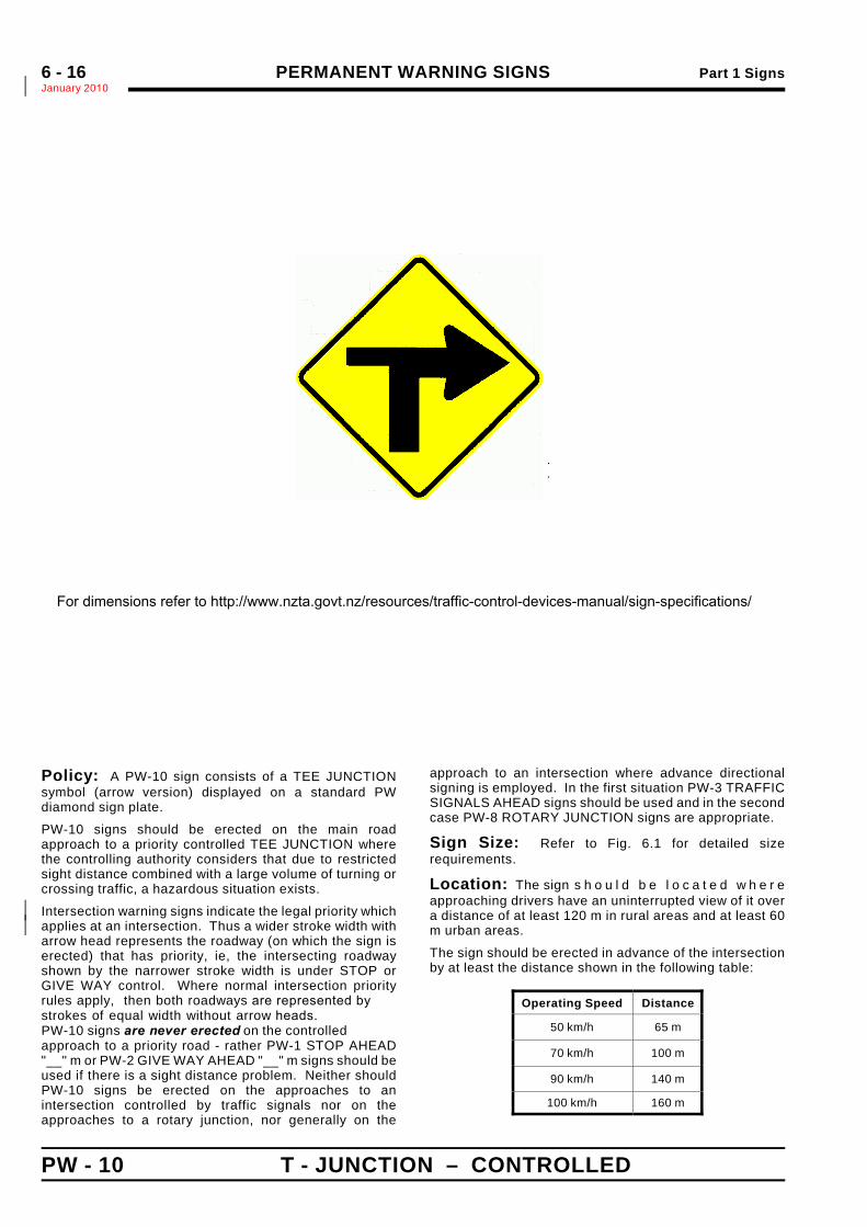
Policy: A PW-10 sign consists of a TEE JUNCTIONsymbol (arrow version) displayed on a standard PWdiamond sign plate.
PW-10 signs should be erected on the main roadapproach to a priority controlled TEE JUNCTION wherethe controlling authority considers that due to restrictedsight distance combined with a large volume of turning orcrossing traffic, a hazardous situation exists.
Intersection warning signs indicate the legal priority which*applies at an intersection. Thus a wider stroke width with*arrow head represents the roadway (on which the sign iserected) that has priority, ie, the intersecting roadwayshown by the narrower stroke width is under STOP orGIVE WAY control. Where normal intersection priorityrules apply, then both roadways are represented bystrokes of equal width without arrow heads.PW-10 signs are never erected on the controlledapproach to a priority road - rather PW-1 STOP AHEAD"__" m or PW-2 GIVE WAY AHEAD "__" m signs should beused if there is a sight distance problem. Neither shouldPW-10 signs be erected on the approaches to anintersection controlled by traffic signals nor on theapproaches to a rotary junction, nor generally on the
approach to an intersection where advance directionalsigning is employed. In the first situation PW-3 TRAFFICSIGNALS AHEAD signs should be used and in the secondcase PW-8 ROTARY JUNCTION signs are appropriate.
Sign Size: Refer to Fig. 6.1 for detailed sizerequirements.
Location: The sign s h o u l d b e l o c a t e d w h e r eapproaching drivers have an uninterrupted view of it overa distance of at least 120 m in rural areas and at least 60m urban areas.
The sign should be erected in advance of the intersectionby at least the distance shown in the following table:
Operating Speed Distance
50 km/h 65 m
70 km/h 100 m
90 km/h 140 m
100 km/h 160 m
ARROW : Type A
NOTE: LH version is mirror image of above
For dimensions refer to http://www.nzta.govt.nz/resources/traffic-control-devices-manual/sign-specifications/
Part 1 Signs PERMANENT WARNING SIGNSJanuary 2010*
6 - 17
T - JUNCTION – UNCONTROLLED PW - 10.1
.
.
Sign Size a b c d600 × 600 100 40 275 165750 ×750 125 50 345 205900 × 900 150 60 415 240
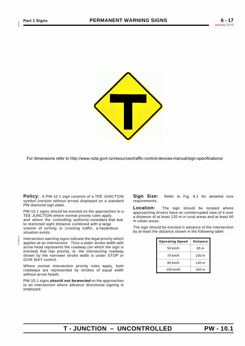
Policy: A PW-10.1 sign consists of a TEE JUNCTIONsymbol (version without arrow) displayed on a standardPW diamond sign plate.
PW-10.1 signs should be erected on the approaches to aTEE JUNCTION where normal priority rules apply, and where the controlling authority considers that dueto restricted sight distance combined with a largevolume of turning or crossing traffic, a hazardoussituation exists.
Intersection warning signs indicate the legal priority which*applies at an intersection. Thus a wider stroke width with*arrow head represents the roadway (on which the sign iserected) that has priority, ie, the intersecting roadwayshown by the narrower stroke width is under STOP orGIVE WAY control.
Where normal intersection priority rules apply, bothroadways are represented by strokes of equal widthwithout arrow heads.
PW-10.1 signs should not be erected on the approachesto an intersection where advance directional signing isemployed.
Sign Size: Refer to Fig. 6.1 for detailed sizerequirements.
Location: The sign should be located whereapproaching drivers have an uninterrupted view of it overa distance of at least 120 m in rural areas and at least 60m urban areas.
The sign should be erected in advance of the intersectionby at least the distance shown in the following table:
Operating Speed Distance
50 km/h 65 m
70 km/h 100 m
90 km/h 140 m
100 km/h 160 m
For dimensions refer to http://www.nzta.govt.nz/resources/traffic-control-devices-manual/sign-specifications/
PERMANENT WARNING SIGNS Part 1 SignsJanuary 2010*6 - 18
PW - 11 SIDE ROAD JUNCTION – CONTROLLED
.
.
Sign Size a b c d e600 × 600 100 250 550 60 200750 ×750 125 310 685 75 250900 × 900 150 375 825 90 300
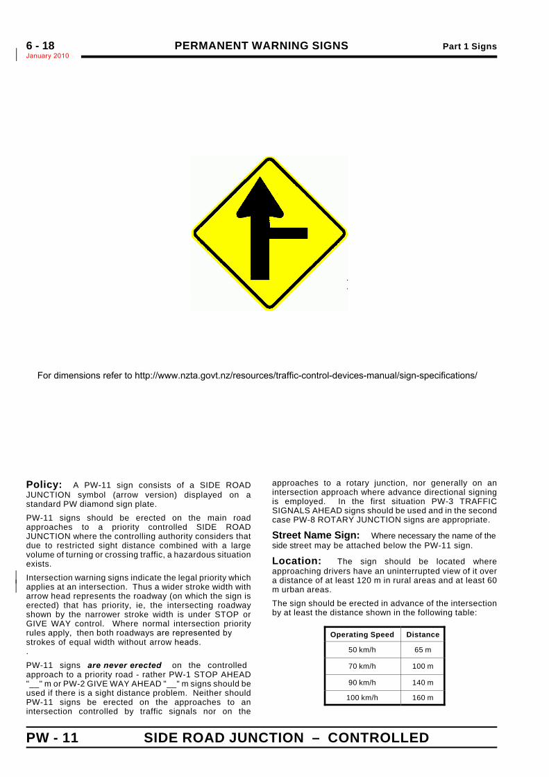
Policy: A PW-11 sign consists of a SIDE ROADJUNCTION symbol (arrow version) displayed on astandard PW diamond sign plate.PW-11 signs should be erected on the main roadapproaches to a priority controlled SIDE ROADJUNCTION where the controlling authority considers thatdue to restricted sight distance combined with a largevolume of turning or crossing traffic, a hazardous situationexists.Intersection warning signs indicate the legal priority which*applies at an intersection. Thus a wider stroke width with*arrow head represents the roadway (on which the sign iserected) that has priority, ie, the intersecting roadwayshown by the narrower stroke width is under STOP orGIVE WAY control. Where normal intersection priorityrules apply, then both roadways are represented bystrokes of equal width without arrow heads..
PW-11 signs are never erected on the controlledapproach to a priority road - rather PW-1 STOP AHEAD"__" m or PW-2 GIVE WAY AHEAD "__" m signs should beused if there is a sight distance problem. Neither shouldPW-11 signs be erected on the approaches to anintersection controlled by traffic signals nor on the
approaches to a rotary junction, nor generally on anintersection approach where advance directional signingis employed. In the first situation PW-3 TRAFFICSIGNALS AHEAD signs should be used and in the secondcase PW-8 ROTARY JUNCTION signs are appropriate.
Street Name Sign: Where necessary the name of the side street may be attached below the PW-11 sign.
Location: The sign should be located whereapproaching drivers have an uninterrupted view of it overa distance of at least 120 m in rural areas and at least 60m urban areas.The sign should be erected in advance of the intersectionby at least the distance shown in the following table:
Operating Speed Distance
50 km/h 65 m
70 km/h 100 m
90 km/h 140 m
100 km/h 160 m
ARROW : Type A
NOTE: LH version is mirror image of above For dimensions refer to http://www.nzta.govt.nz/resources/traffic-control-devices-manual/sign-specifications/
Part 1 Signs PERMANENT WARNING SIGNSJanuary 2010%
6 - 19
SIDE ROAD JUNCTION – UNCONTROLLED PW - 11.1
.
.
Sign Size a b600 × 600 100 205750 ×750 125 255900 × 900 150 305
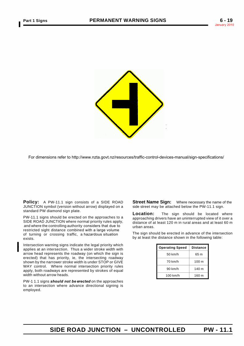
Policy: A PW-11.1 sign consists of a SIDE ROADJUNCTION symbol (version without arrow) displayed on astandard PW diamond sign plate.
PW-11.1 signs should be erected on the approaches to aSIDE ROAD JUNCTION where normal priority rules apply, and where the controlling authority considers that due torestricted sight distance combined with a large volumeof turning or crossing traffic, a hazardous situationexists.
Intersection warning signs indicate the legal priority which%applies at an intersection. Thus a wider stroke width with%arrow head represents the roadway (on which the sign iserected) that has priority, ie, the intersecting roadwayshown by the narrower stroke width is under STOP or GIVEWAY control. Where normal intersection priority rulesapply, both roadways are represented by strokes of equalwidth without arrow heads.
PW-1 1.1 signs should not be erected on the approachesto an intersection where advance directional signing isemployed.
Street Name Sign: Where necessary the name of theside street may be attached below the PW-11.1 sign.
Location: The sign should be located whereapproaching drivers have an uninterrupted view of it over adistance of at least 120 m in rural areas and at least 60 murban areas.
The sign should be erected in advance of the intersectionby at least the distance shown in the following table:
Operating Speed Distance
50 km/h 65 m
70 km/h 100 m
90 km/h 140 m
100 km/h 160 m
NOTE: RH version is mirror image of above For dimensions refer to http://www.nzta.govt.nz/resources/traffic-control-devices-manual/sign-specifications/
PERMANENT WARNING SIGNS Part 1 SignsJanuary 2010*6 - 20
PW - 12 Y - JUNCTION – CONTROLLED
.
.
Sign Size a b c d e f600 × 600 100 250 160 60 40 240750 ×750 125 310 200 75 50 300900 × 900 150 375 240 90 60 360
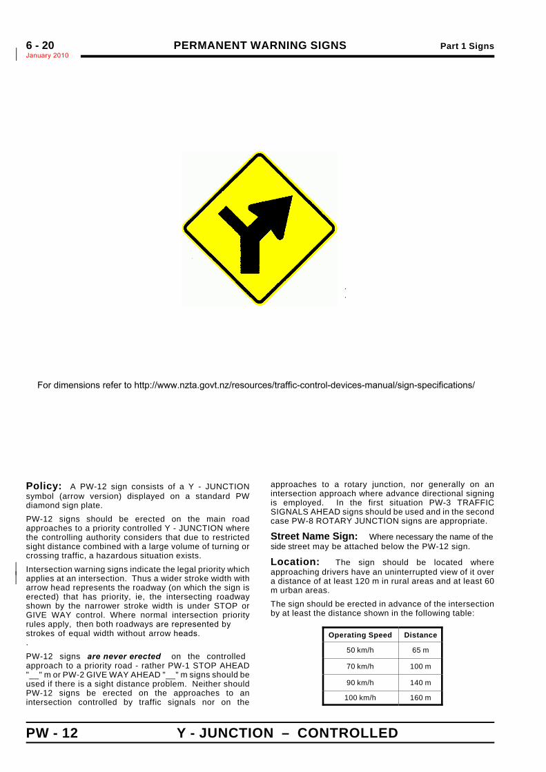
Policy: A PW-12 sign consists of a Y - JUNCTIONsymbol (arrow version) displayed on a standard PWdiamond sign plate.PW-12 signs should be erected on the main roadapproaches to a priority controlled Y - JUNCTION wherethe controlling authority considers that due to restrictedsight distance combined with a large volume of turning orcrossing traffic, a hazardous situation exists.Intersection warning signs indicate the legal priority which*applies at an intersection. Thus a wider stroke width with*arrow head represents the roadway (on which the sign iserected) that has priority, ie, the intersecting roadwayshown by the narrower stroke width is under STOP orGIVE WAY control. Where normal intersection priorityrules apply, then both roadways are represented bystrokes of equal width without arrow heads..
PW-12 signs are never erected on the controlledapproach to a priority road - rather PW-1 STOP AHEAD"__" m or PW-2 GIVE WAY AHEAD "__" m signs should beused if there is a sight distance problem. Neither shouldPW-12 signs be erected on the approaches to anintersection controlled by traffic signals nor on the
approaches to a rotary junction, nor generally on anintersection approach where advance directional signingis employed. In the first situation PW-3 TRAFFICSIGNALS AHEAD signs should be used and in the secondcase PW-8 ROTARY JUNCTION signs are appropriate.
Street Name Sign: Where necessary the name of the side street may be attached below the PW-12 sign.
Location: The sign should be located whereapproaching drivers have an uninterrupted view of it overa distance of at least 120 m in rural areas and at least 60m urban areas.The sign should be erected in advance of the intersectionby at least the distance shown in the following table:
Operating Speed Distance
50 km/h 65 m
70 km/h 100 m
90 km/h 140 m
100 km/h 160 m
ARROW : Type A
NOTE: LH version is mirror image of above For dimensions refer to http://www.nzta.govt.nz/resources/traffic-control-devices-manual/sign-specifications/
Part 1 Signs PERMANENT WARNING SIGNSJanuary 2010*
6 - 21
Y - JUNCTION – UNCONTROLLED PW - 12.
.
.
Sign Size a b c d600 × 600 100 210 85 110750 ×750 125 260 105 135900 × 900 150 315 125 165
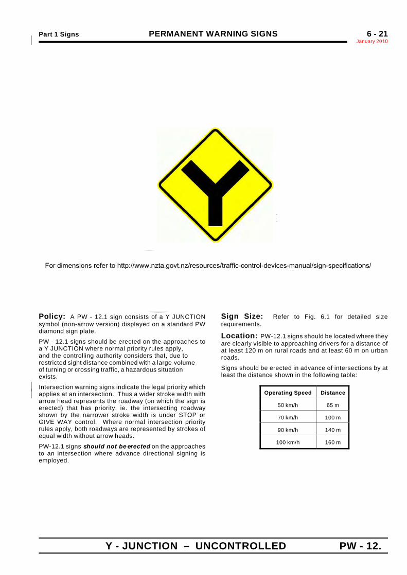
Policy: A PW - 12.1 sign consists of a Y JUNCTIONsymbol (non-arrow version) displayed on a standard PWdiamond sign plate.
PW - 12.1 signs should be erected on the approaches toa Y JUNCTION where normal priority rules apply, and the controlling authority considers that, due torestricted sight distance combined with a large volumeof turning or crossing traffic, a hazardous situationexists.
Intersection warning signs indicate the legal priority which*applies at an intersection. Thus a wider stroke width with*arrow head represents the roadway (on which the sign iserected) that has priority, ie. the intersecting roadwayshown by the narrower stroke width is under STOP orGIVE WAY control. Where normal intersection priorityrules apply, both roadways are represented by strokes ofequal width without arrow heads.
PW-12.1 signs should not be erected on the approachesto an intersection where advance directional signing isemployed.
Sign Size: Refer to Fig. 6.1 for detailed sizerequirements.
Location: PW-12.1 signs should be located where theyare clearly visible to approaching drivers for a distance ofat least 120 m on rural roads and at least 60 m on urbanroads.
Signs should be erected in advance of intersections by atleast the distance shown in the following table:
Operating Speed Distance
50 km/h 65 m
70 km/h 100 m
90 km/h 140 m
100 km/h 160 m
For dimensions refer to http://www.nzta.govt.nz/resources/traffic-control-devices-manual/sign-specifications/
PERMANENT WARNING SIGNS Part 1 SignsJanuary 2010*6 - 22
RAILWAY CROSSING ON SIDE ROADPW - 13 CONTROLLED JUNCTION
.
.
Sign Size a b c d e f g h × 600 80 250 100 110 25 50 300 150750 ×750 100 310 125 135 30 60 375 180900 × 900 120 370 150 160 35 70 450 225
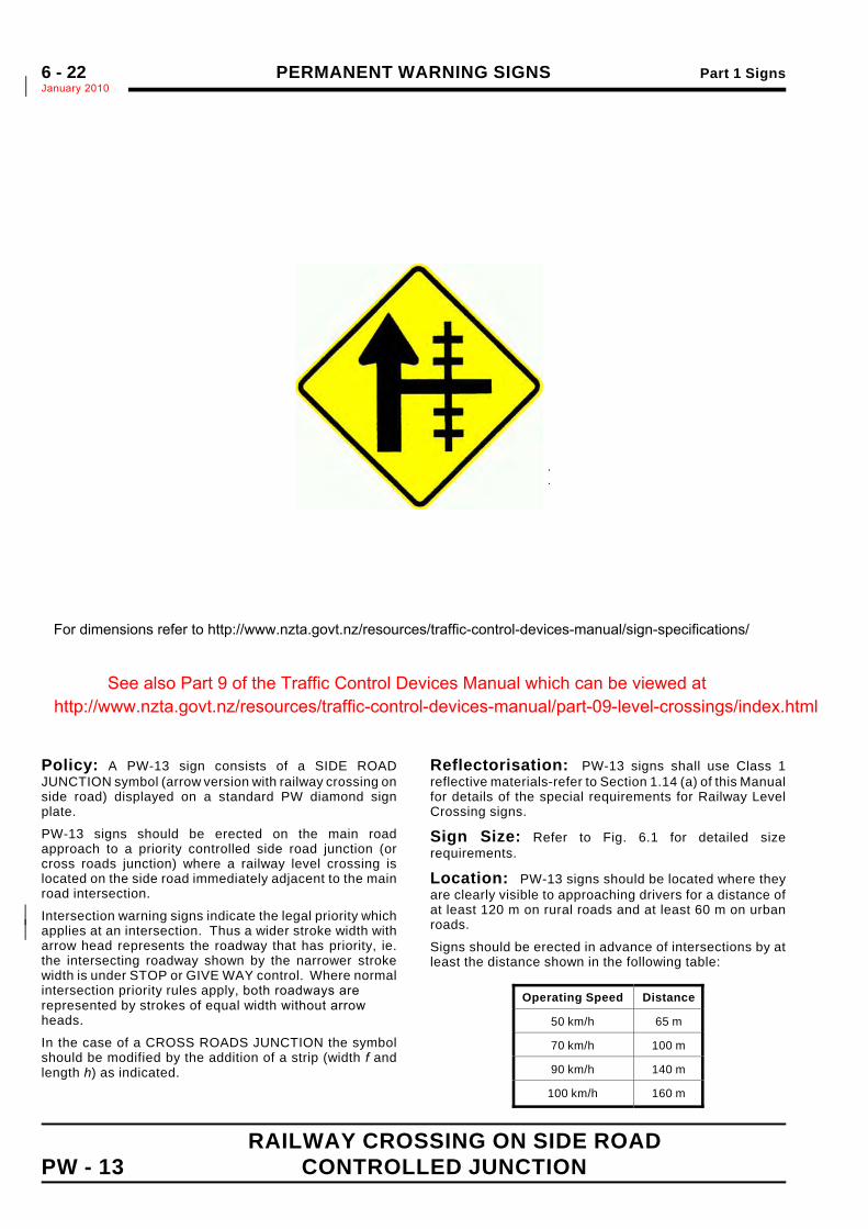
Policy: A PW-13 sign consists of a SIDE ROADJUNCTION symbol (arrow version with railway crossing onside road) displayed on a standard PW diamond signplate.
PW-13 signs should be erected on the main roadapproach to a priority controlled side road junction (orcross roads junction) where a railway level crossing islocated on the side road immediately adjacent to the mainroad intersection.
Intersection warning signs indicate the legal priority which*applies at an intersection. Thus a wider stroke width with*arrow head represents the roadway that has priority, ie.the intersecting roadway shown by the narrower strokewidth is under STOP or GIVE WAY control. Where normalintersection priority rules apply, both roadways arerepresented by strokes of equal width without arrowheads.
In the case of a CROSS ROADS JUNCTION the symbolshould be modified by the addition of a strip (width f andlength h) as indicated.
Reflectorisation: PW-13 signs shall use Class 1reflective materials-refer to Section 1.14 (a) of this Manualfor details of the special requirements for Railway LevelCrossing signs.
Sign Size: Refer to Fig. 6.1 for detailed sizerequirements.
Location: PW-13 signs should be located where theyare clearly visible to approaching drivers for a distance ofat least 120 m on rural roads and at least 60 m on urbanroads.
Signs should be erected in advance of intersections by atleast the distance shown in the following table:
Operating Speed Distance
50 km/h 65 m
70 km/h 100 m
90 km/h 140 m
100 km/h 160 m
ARROW : Type A
NOTE: LH version is mirrorimage of above
For dimensions refer to http://www.nzta.govt.nz/resources/traffic-control-devices-manual/sign-specifications/
See also Part 9 of the Traffic Control Devices Manual which can be viewed at http://www.nzta.govt.nz/resources/traffic-control-devices-manual/part-09-level-crossings/index.html
Part 1 Signs PERMANENT WARNING SIGNSJanuary 2010*
6 - 23
RAILWAY CROSSING ON SIDE ROAD UNCONTROLLED JUNCTION PW - 13.1
.
.
Sign Size a b c d e f g600× 600 80 60 50 100 90 200 25750 ×750 100 75 60 125 110 250 30900 × 900 120 90 75 150 135 300 35
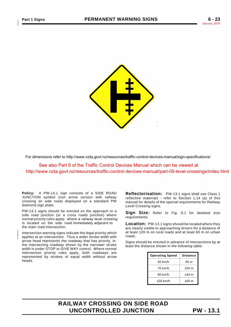
Policy: A PW-13.1 sign consists of a SIDE ROADJUNCTION symbol (non arrow version with railwaycrossing on side road) displayed on a standard PWdiamond sign plate.
PW-13.1 signs should be erected on the approach to aside road junction (or a cross roads junction) wherenormal priority rules apply, where a railway level crossingis located on the side road immediately adjacent tothe main road intersection.
Intersection warning signs indicate the legal priority which*applies at an intersection. Thus a wider stroke width with*arrow head represents the roadway that has priority, ie.the intersecting roadway shown by the narrower strokewidth is under STOP or GIVE WAY control. Where normalintersection priority rules apply, both roadways arerepresented by strokes of equal width without arrowheads.
Reflectorisation: PW-13.1 signs shall use Class 1reflective materials - refer to Section 1.14 (a) of thismanual for details of the special requirements for RailwayLevel Crossing signs.
Sign Size: Refer to Fig. 6.1 for detailed sizerequirements.
Location: PW-13.1 signs should be located where theyare clearly visible to approaching drivers for a distance ofat least 120 m on rural roads and at least 60 m on urbanroads.
Signs should be erected in advance of intersections by atleast the distance shown in the following table:
Operating Speed Distance
50 km/h 65 m
70 km/h 100 m
90 km/h 140 m
100 km/h 160 m
ARROW : Type A
NOTE: LH version is mirrorimage of above
For dimensions refer to http://www.nzta.govt.nz/resources/traffic-control-devices-manual/sign-specifications/
See also Part 9 of the Traffic Control Devices Manual which can be viewed at http://www.nzta.govt.nz/resources/traffic-control-devices-manual/part-09-level-crossings/index.html
PERMANENT WARNING SIGNS Part 1 SignsJanuary 2010*6 - 24
RAILWAY CROSSING AT T - JUNCTIONPW - 13.2 CONTROLLED JUNCTION
.
.
Sign Size a b c d e f g600 × 600 80 60 50 100 90 200 25750 ×750 100 75 60 125 110 250 30900 × 900 120 90 75 150 135 300 35
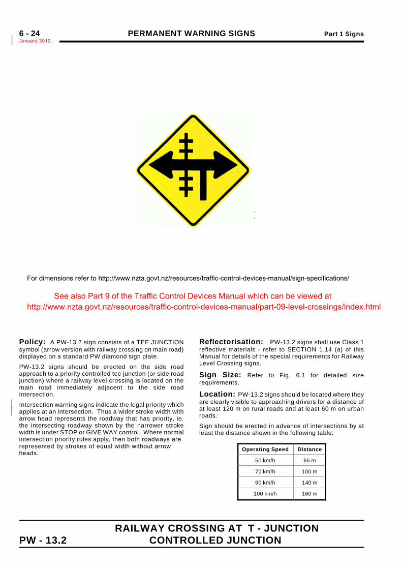
Policy: A PW-13.2 sign consists of a TEE JUNCTIONsymbol (arrow version with railway crossing on main road)displayed on a standard PW diamond sign plate.
PW-13.2 signs should be erected on the side roadapproach to a priority controlled tee junction (or side roadjunction) where a railway level crossing is located on themain road immediately adjacent to the side roadintersection.
Intersection warning signs indicate the legal priority which*applies at an intersection. Thus a wider stroke width with*arrow head represents the roadway that has priority, ie.the intersecting roadway shown by the narrower strokewidth is under STOP or GIVE WAY control. Where normalintersection priority rules apply, then both roadways arerepresented by strokes of equal width without arrowheads.
Reflectorisation: PW-13.2 signs shall use Class 1reflective materials - refer to SECTION 1.14 (a) of thisManual for details of the special requirements for RailwayLevel Crossing signs.
Sign Size: Refer to Fig. 6.1 for detailed sizerequirements.
Location: PW-13.2 signs should be located where theyare clearly visible to approaching drivers for a distance ofat least 120 m on rural roads and at least 60 m on urbanroads.
Sign should be erected in advance of intersections by atleast the distance shown in the following table:
Operating Speed Distance
50 km/h 65 m
70 km/h 100 m
90 km/h 140 m
100 km/h 160 m
ARROW : Type A
NOTE: LH version is mirrorimage of above
For dimensions refer to http://www.nzta.govt.nz/resources/traffic-control-devices-manual/sign-specifications/
See also Part 9 of the Traffic Control Devices Manual which can be viewed at http://www.nzta.govt.nz/resources/traffic-control-devices-manual/part-09-level-crossings/index.html
Part 1 Signs PERMANENT WARNING SIGNSJanuary 2010*
6 - 25
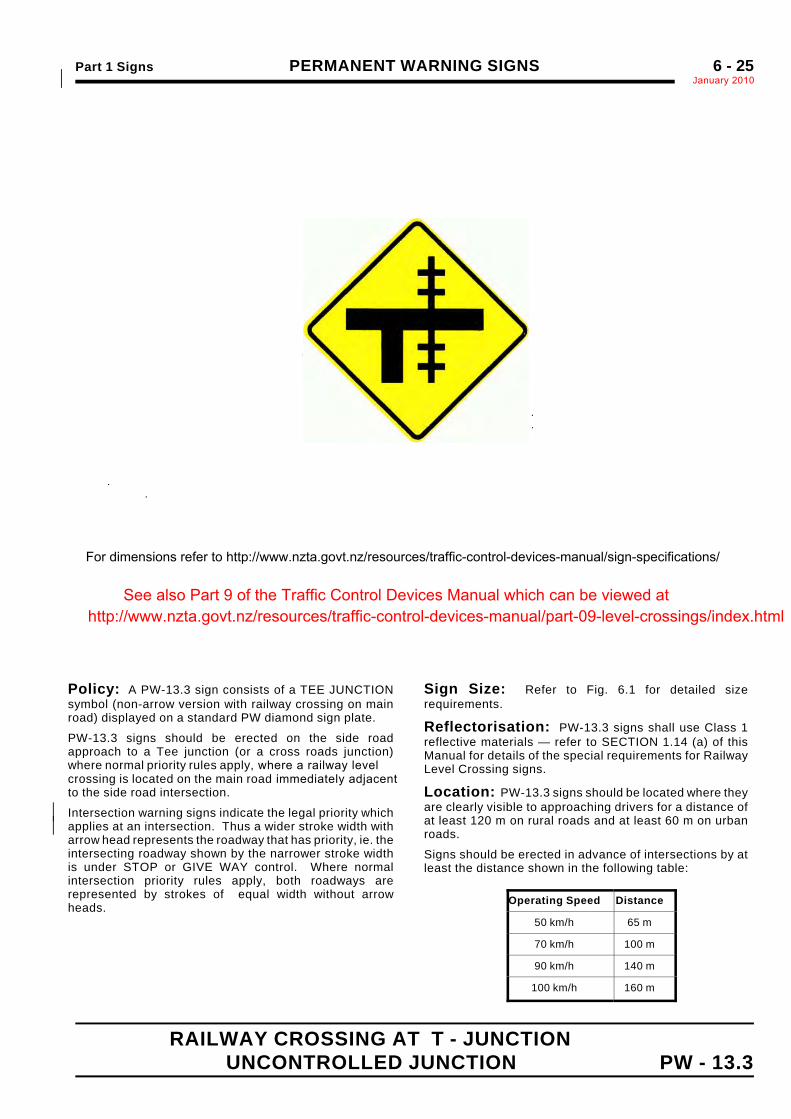
RAILWAY CROSSING AT T - JUNCTIONUNCONTROLLED JUNCTION PW - 13.3
.
.
Sign Size a b c d e f g600 × 600 80 60 50 100 90 200 25750 ×750 100 75 60 125 110 250 30900 × 900 120 90 75 150 135 300 35
Policy: A PW-13.3 sign consists of a TEE JUNCTIONsymbol (non-arrow version with railway crossing on mainroad) displayed on a standard PW diamond sign plate.
PW-13.3 signs should be erected on the side roadapproach to a Tee junction (or a cross roads junction)where normal priority rules apply, where a railway levelcrossing is located on the main road immediately adjacentto the side road intersection.
Intersection warning signs indicate the legal priority which*applies at an intersection. Thus a wider stroke width with*arrow head represents the roadway that has priority, ie. theintersecting roadway shown by the narrower stroke widthis under STOP or GIVE WAY control. Where normalintersection priority rules apply, both roadways arerepresented by strokes of equal width without arrowheads.
Sign Size: Refer to Fig. 6.1 for detailed sizerequirements.
Reflectorisation: PW-13.3 signs shall use Class 1reflective materials — refer to SECTION 1.14 (a) of thisManual for details of the special requirements for RailwayLevel Crossing signs.
Location: PW-13.3 signs should be located where theyare clearly visible to approaching drivers for a distance ofat least 120 m on rural roads and at least 60 m on urbanroads.
Signs should be erected in advance of intersections by atleast the distance shown in the following table:
Operating Speed Distance
50 km/h 65 m
70 km/h 100 m
90 km/h 140 m
100 km/h 160 m
..
For dimensions refer to http://www.nzta.govt.nz/resources/traffic-control-devices-manual/sign-specifications/
See also Part 9 of the Traffic Control Devices Manual which can be viewed at http://www.nzta.govt.nz/resources/traffic-control-devices-manual/part-09-level-crossings/index.html
PERMANENT WARNING SIGNS Part 1 SignsJanuary 2010*6 - 26
RAILWAY LEVEL CROSSING POSITIONPW - 14 INDICATOR (Crossbuck)
Optional Target Board
Sign a b c d e f g h j k Height Width Border
PW-14a* 767* 284* 50* 200* 57* 313* 851* 1000* 133 C* 133 D* 875 1170 25
PW-14b 1150 426 75 300 85 470 1277 1500 200 C 200 D 1310 1750 40
Policy: PW-14 RAILWAY CROSSING POSITIONINDICATOR or "Crossbuck" signs shall be erected at allrailway level crossings, as part of RG-30, RG-31 or RG-32sign combinations erected at the crossings.
The PW-14 sign is part of an RG-31, RG-32 o r RG-33*railway level crossing sign combination and is nevererected separately.
Where increased conspicuity is required the PW-14 signmay be mounted on a red reflectorised target board, tomake it more effective when viewed against:
! a visually complex background, or! a background which is of light colour for a substantial
proportion of the time.
Reflectorisation: PW-14 signs shall use Class 1reflective materials — refer to SECTION 1.14 (a) of thisManual for details of the special requirements for RailwayLevel Crossing signs.
Sign Size: Sign size should be determined from thefollowing table :
Operating SpeedV85 (km/h) Sign Type
# 70 (Urban roads)
A PW-14b sign should normally beused in all situations but a PW-14asign may be used at restrictedurban sites
> 70 (Rural roads) A PW-14b sign shall be used in allrural situations
For dimensions refer to http://www.landtransport.govt.nz/roads/tcd/sign-pw-category-permanent-warning.html
This section has been replaced with Part 9 of the Traffic Control Devices Manual which can be viewed at http://www.nzta.govt.nz/resources/traffic-control-devices-manual/part-09-level-crossings/index.html
Part 1 Signs PERMANENT WARNING SIGNSJanuary 2010*
6 - 27
RAILWAY LEVEL CROSSING "__" TRACKS PW - 15
*
*
*
*
*
*
*
*
*
*
*
*
*
*
*
*
*
*
*
*
Sign a b c d e f g Lettering for the word"MULTIPLE"
PW-15a 350 305 120 130 75 C 150 100 C 75 C
PW-15b 525 416 175 175 100 C 225 150 C 100 C
This section has been replaced with Part 9 of the Traffic Control Devices Manual which can be viewed at http://www.nzta.govt.nz/resources/traffic-control-devices-manual/part-09-level-crossings/index.html
PERMANENT WARNING SIGNS Part 1 SignsJanuary 20106 - 28
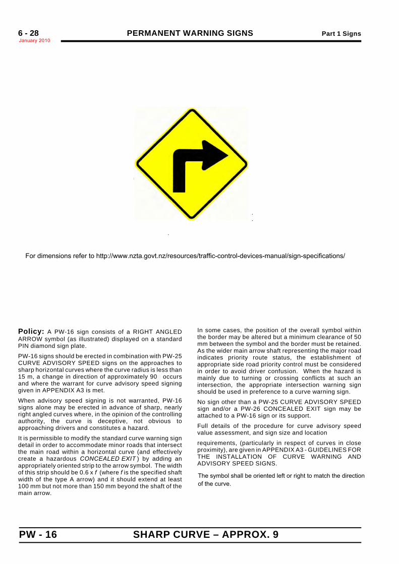
PW - 16 SHARP CURVE – APPROX. 9
.
.
Sign Size a b c d e f g h600 x 600 315 210 50 10 270 90 310 50
750 x 750 395 260 60 15 340 110 390 60
900 x 900 475 310 70 20 410 130 470 70
1200 x 1200 630 420 100 20 540 410 620 100
Policy: A PW-16 sign consists of a RIGHT ANGLEDARROW symbol (as illustrated) displayed on a standardPIN diamond sign plate.
PW-16 signs should be erected in combination with PW-25CURVE ADVISORY SPEED signs on the approaches tosharp horizontal curves where the curve radius is less than15 m, a change in direction of approximately 90! occursand where the warrant for curve advisory speed signinggiven in APPENDIX A3 is met.
When advisory speed signing is not warranted, PW-16signs alone may be erected in advance of sharp, nearlyright angled curves where, in the opinion of the controllingauthority, the curve is deceptive, not obvious toapproaching drivers and constitutes a hazard.
It is permissible to modify the standard curve warning signdetail in order to accommodate minor roads that intersectthe main road within a horizontal curve (and effectivelycreate a hazardous CONCEALED EXIT ) by adding anappropriately oriented strip to the arrow symbol. The widthof this strip should be 0.6 x f (where f is the specified shaftwidth of the type A arrow) and it should extend at least100 mm but not more than 150 mm beyond the shaft of themain arrow.
In some cases, the position of the overall symbol withinthe border may be altered but a minimum clearance of 50mm between the symbol and the border must be retained.As the wider main arrow shaft representing the major roadindicates priority route status, the establishment ofappropriate side road priority control must be consideredin order to avoid driver confusion. When the hazard ismainly due to turning or crossing conflicts at such anintersection, the appropriate intersection warning signshould be used in preference to a curve warning sign.
No sign other than a PW-25 CURVE ADVISORY SPEEDsign and/or a PW-26 CONCEALED EXIT sign may beattached to a PW-16 sign or its support.
Full details of the procedure for curve advisory speedvalue assessment, and sign size and location
requirements, (particularly in respect of curves in closeproximity), are given in APPENDIX A3 - GUIDELINES FORTHE INSTALLATION OF CURVE WARNING ANDADVISORY SPEED SIGNS.
ARROW : Type A
NOTE: LH version is mirrorimage of above
For dimensions refer to http://www.nzta.govt.nz/resources/traffic-control-devices-manual/sign-specifications/
The symbol shall be oriented left or right to match the directionof the curve.
Part 1 Signs PERMANENT WARNING SIGNSJanuary 2010
6 - 29
CURVE – 15/ TO 90/ PW - 17
.
.
Sign Size a b c d e600 x 600 215 190 70 90 60
750 x 750 270 235 90 110 75
900 x 900 325 280 110 130 90
1200 x 1200 430 380 140 180 120
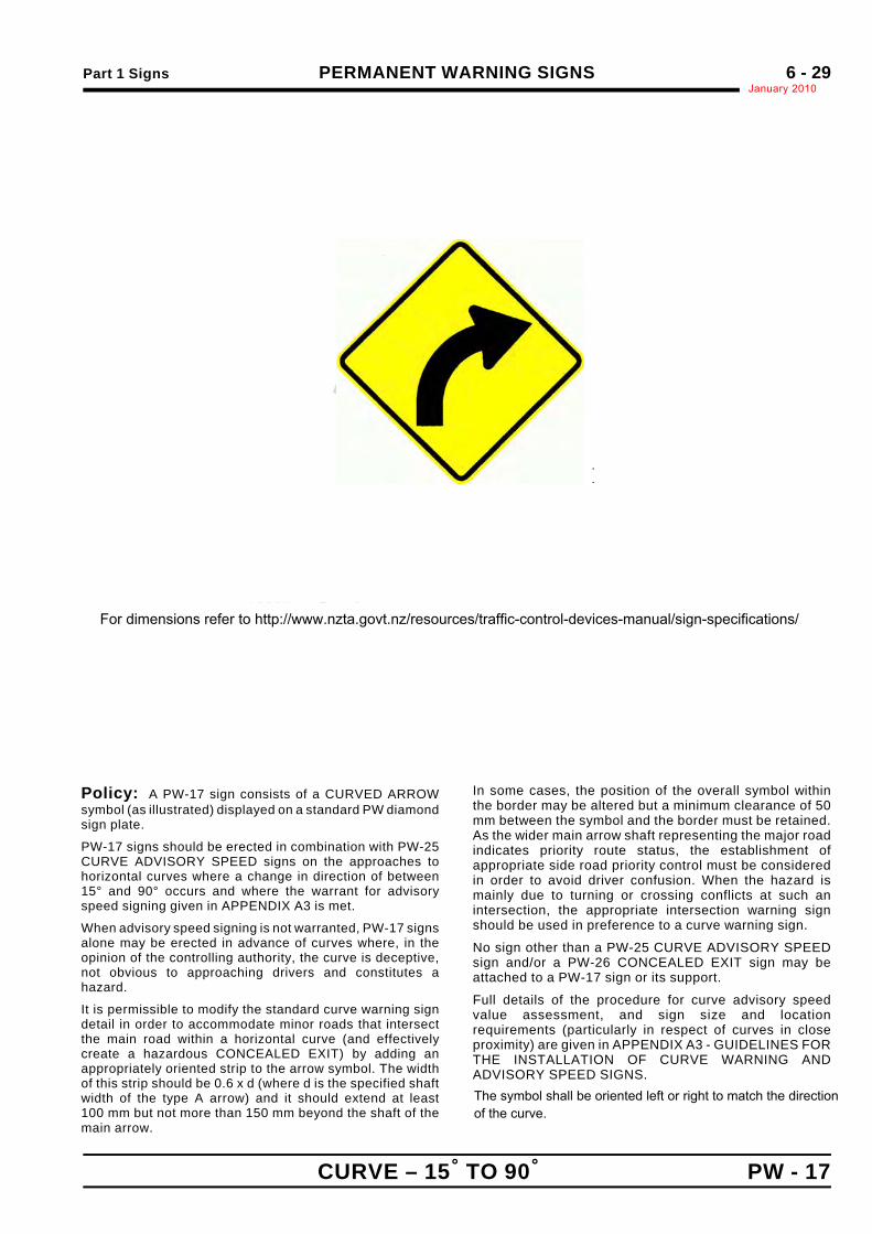
Policy: A PW-17 sign consists of a CURVED ARROWsymbol (as illustrated) displayed on a standard PW diamondsign plate.
PW-17 signs should be erected in combination with PW-25CURVE ADVISORY SPEED signs on the approaches tohorizontal curves where a change in direction of between15° and 90° occurs and where the warrant for advisoryspeed signing given in APPENDIX A3 is met.
When advisory speed signing is not warranted, PW-17 signsalone may be erected in advance of curves where, in theopinion of the controlling authority, the curve is deceptive,not obvious to approaching drivers and constitutes ahazard.
It is permissible to modify the standard curve warning signdetail in order to accommodate minor roads that intersectthe main road within a horizontal curve (and effectivelycreate a hazardous CONCEALED EXIT) by adding anappropriately oriented strip to the arrow symbol. The widthof this strip should be 0.6 x d (where d is the specified shaftwidth of the type A arrow) and it should extend at least100 mm but not more than 150 mm beyond the shaft of themain arrow.
In some cases, the position of the overall symbol withinthe border may be altered but a minimum clearance of 50mm between the symbol and the border must be retained.As the wider main arrow shaft representing the major roadindicates priority route status, the establishment ofappropriate side road priority control must be consideredin order to avoid driver confusion. When the hazard ismainly due to turning or crossing conflicts at such anintersection, the appropriate intersection warning signshould be used in preference to a curve warning sign.
No sign other than a PW-25 CURVE ADVISORY SPEEDsign and/or a PW-26 CONCEALED EXIT sign may beattached to a PW-17 sign or its support.
Full details of the procedure for curve advisory speedvalue assessment, and sign size and locationrequirements (particularly in respect of curves in closeproximity) are given in APPENDIX A3 - GUIDELINES FORTHE INSTALLATION OF CURVE WARNING ANDADVISORY SPEED SIGNS.
ARROW : Type A
NOTE: LH version is mirrorimage of above
For dimensions refer to http://www.nzta.govt.nz/resources/traffic-control-devices-manual/sign-specifications/
The symbol shall be oriented left or right to match the directionof the curve.
PERMANENT WARNING SIGNS Part 1 SignsJanuary 20106 - 30
PW - 18 CURVE – 90/ TO 120/
.
.ARROW : Type A
NOTE: LH version is mirrorimage of above
Sign Size a b c d e600 x 600 150 80 120 160 50
750 x 750 185 100 150 200 60
900 x 900 220 120 180 240 70
1200 x 1200 300 160 240 320 100
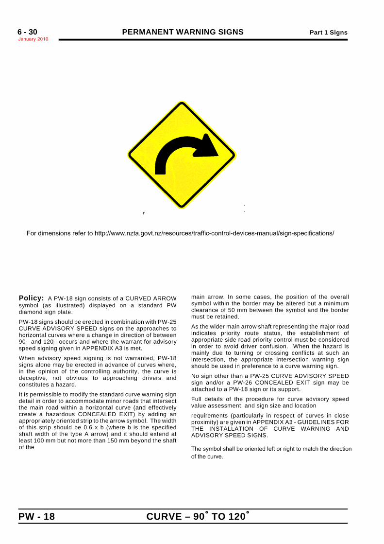
Policy: A PW-18 sign consists of a CURVED ARROWsymbol (as illustrated) displayed on a standard PWdiamond sign plate.
PW-18 signs should be erected in combination with PW-25CURVE ADVISORY SPEED signs on the approaches tohorizontal curves where a change in direction of between90! and 120! occurs and where the warrant for advisoryspeed signing given in APPENDIX A3 is met.
When advisory speed signing is not warranted, PW-18signs alone may be erected in advance of curves where,in the opinion of the controlling authority, the curve isdeceptive, not obvious to approaching drivers andconstitutes a hazard.
It is permissible to modify the standard curve warning signdetail in order to accommodate minor roads that intersectthe main road within a horizontal curve (and effectivelycreate a hazardous CONCEALED EXIT) by adding anappropriately oriented strip to the arrow symbol. The widthof this strip should be 0.6 x b (where b is the specifiedshaft width of the type A arrow) and it should extend atleast 100 mm but not more than 150 mm beyond the shaftof the
main arrow. In some cases, the position of the overallsymbol within the border may be altered but a minimumclearance of 50 mm between the symbol and the bordermust be retained.
As the wider main arrow shaft representing the major roadindicates priority route status, the establishment ofappropriate side road priority control must be consideredin order to avoid driver confusion. When the hazard ismainly due to turning or crossing conflicts at such anintersection, the appropriate intersection warning signshould be used in preference to a curve warning sign.
No sign other than a PW-25 CURVE ADVISORY SPEEDsign and/or a PW-26 CONCEALED EXIT sign may beattached to a PW-18 sign or its support.
Full details of the procedure for curve advisory speedvalue assessment, and sign size and location
requirements (particularly in respect of curves in closeproximity) are given in APPENDIX A3 - GUIDELINES FORTHE INSTALLATION OF CURVE WARNING ANDADVISORY SPEED SIGNS.
For dimensions refer to http://www.nzta.govt.nz/resources/traffic-control-devices-manual/sign-specifications/
The symbol shall be oriented left or right to match the directionof the curve.
Part 1 Signs PERMANENT WARNING SIGNSJanuary 2010
6 - 31
CURVE – GREATER THAN 120/ PW - 1
.
.
ARROW : Type A
NOTE: LH version is mirrorimage of above
Sign Size a b c d e f g600 x 600 220 50 90 330 275 70 30
750 x 750 275 65 110 415 335 85 35
900 x 900 330 80 130 500 395 100 40
1200 x 1200 440 100 180 660 550 140 60
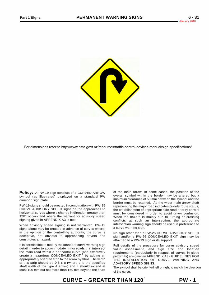
Policy: A PW-19 sign consists of a CURVED ARROWsymbol (as illustrated) displayed on a standard PWdiamond sign plate.
PW-19 signs should be erected in combination with PW-25CURVE ADVISORY SPEED signs on the approaches tohorizontal curves where a change in direction greater than120° occurs and where the warrant for advisory speedsigning given in APPENDIX A3 is met.
When advisory speed signing is not warranted, PW-19signs alone may be erected in advance of curves where,in the opinion of the controlling authority, the curve isdeceptive, not obvious to approaching drivers andconstitutes a hazard.
It is permissible to modify the standard curve warning signdetail in order to accommodate minor roads that intersectthe main road within a horizontal curve (and effectivelycreate a hazardous CONCEALED EXIT ) by adding anappropriately oriented strip to the arrow symbol. The widthof this strip should be 0.6 x c (where c is the specifiedshaft width of the type A arrow) and it should extend atleast 100 mm but not more than 150 mm beyond the shaft
of the main arrow. In some cases, the position of theoverall symbol within the border may be altered but aminimum clearance of 50 mm between the symbol and theborder must be retained. As the wider main arrow shaftrepresenting the major road indicates priority route status,the establishment of appropriate side road priority controlmust be considered in order to avoid driver confusion.When the hazard is mainly due to turning or crossingconflicts at such an intersection, the appropriateintersection warning sign should be used in preference toa curve warning sign.
No sign other than a PW-25 CURVE ADVISORY SPEEDsign and/or a PW-26 CONCEALED EXIT sign may beattached to a PW-19 sign or its support.
Full details of the procedure for curve advisory speedvalue assessment, and sign size and locationrequirements (particularly in respect of curves in closeproximity) are given in APPENDIX A3 - GUIDELINES FORTHE INSTALLATION OF CURVE WARNING ANDADVISORY SPEED SIGNS.
For dimensions refer to http://www.nzta.govt.nz/resources/traffic-control-devices-manual/sign-specifications/
The symbol shall be oriented left or right to match the directionof the curve.
PERMANENT WARNING SIGNS Part 1 SignsJanuary 20106 - 32
PW - 20 REVERSE CURVE – LESS THAN 60/
.
.
ARROW : Type A
NOTE: LH version is mirrorimage of above
Sign Size a b c d e f g h j k600 x 600 120 100 50 70 120 140 80 80 80 80
750 x 750 210 125 60 85 150 175 100 100 100 100
900 x 900 250 145 70 100 180 210 120 120 120 120
1200 x 1200 340 200 100 140 240 280 160 160 160 160
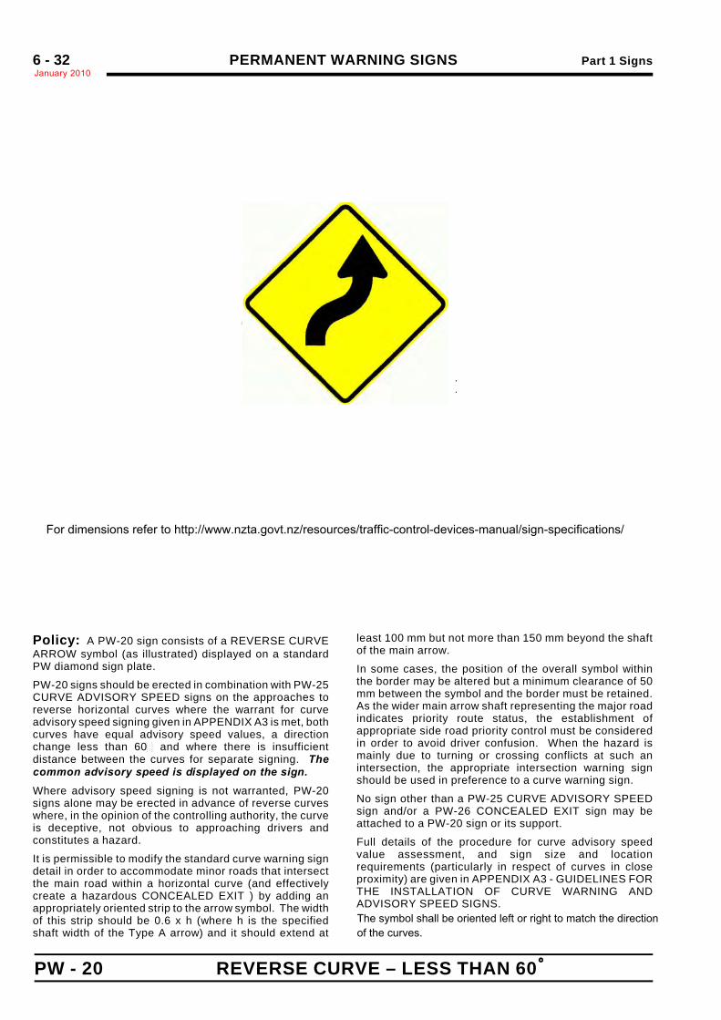
Policy: A PW-20 sign consists of a REVERSE CURVEARROW symbol (as illustrated) displayed on a standardPW diamond sign plate.
PW-20 signs should be erected in combination with PW-25CURVE ADVISORY SPEED signs on the approaches toreverse horizontal curves where the warrant for curveadvisory speed signing given in APPENDIX A3 is met, bothcurves have equal advisory speed values, a directionchange less than 60! and where there is insufficientdistance between the curves for separate signing. Thecommon advisory speed is displayed on the sign.
Where advisory speed signing is not warranted, PW-20signs alone may be erected in advance of reverse curveswhere, in the opinion of the controlling authority, the curveis deceptive, not obvious to approaching drivers andconstitutes a hazard.
It is permissible to modify the standard curve warning signdetail in order to accommodate minor roads that intersectthe main road within a horizontal curve (and effectivelycreate a hazardous CONCEALED EXIT ) by adding anappropriately oriented strip to the arrow symbol. The widthof this strip should be 0.6 x h (where h is the specifiedshaft width of the Type A arrow) and it should extend at
least 100 mm but not more than 150 mm beyond the shaftof the main arrow.
In some cases, the position of the overall symbol withinthe border may be altered but a minimum clearance of 50mm between the symbol and the border must be retained.As the wider main arrow shaft representing the major roadindicates priority route status, the establishment ofappropriate side road priority control must be consideredin order to avoid driver confusion. When the hazard ismainly due to turning or crossing conflicts at such anintersection, the appropriate intersection warning signshould be used in preference to a curve warning sign.
No sign other than a PW-25 CURVE ADVISORY SPEEDsign and/or a PW-26 CONCEALED EXIT sign may beattached to a PW-20 sign or its support.
Full details of the procedure for curve advisory speedvalue assessment, and sign size and locationrequirements (particularly in respect of curves in closeproximity) are given in APPENDIX A3 - GUIDELINES FORTHE INSTALLATION OF CURVE WARNING ANDADVISORY SPEED SIGNS.
For dimensions refer to http://www.nzta.govt.nz/resources/traffic-control-devices-manual/sign-specifications/
The symbol shall be oriented left or right to match the directionof the curves.
Part 1 Signs PERMANENT WARNING SIGNSJanuary 2010
6 - 33
REVERSE CURVE – GREATER THAN 60/ PW - 21
.
.
ARROW: Type A
NOTE: LH version is mirrorimage of above
Sign Size a b c d e f g h j k l600 x 600 80 30 70 20 40 50 90 70 30 30 100
750 x 750 100 40 90 25 50 60 115 90 40 40 125
900 x 900 120 45 105 30 60 75 135 105 45 45 150
1200 x 1200 160 60 140 40 80 100 180 140 60 60 200
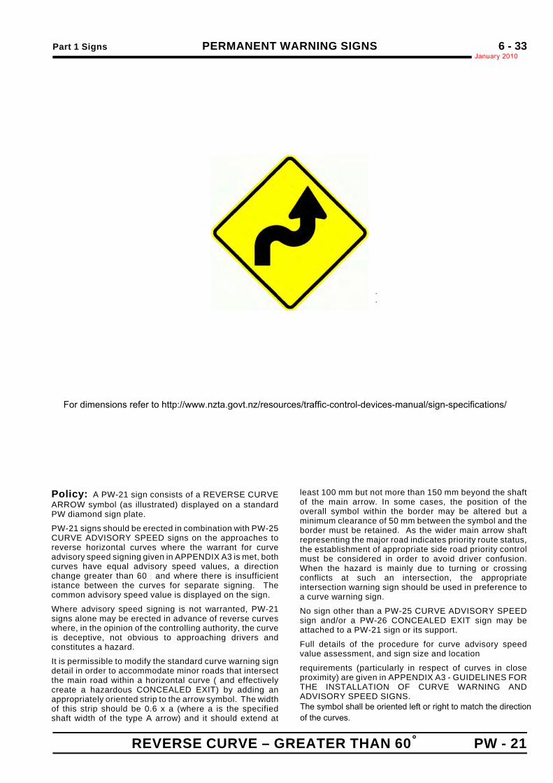
Policy: A PW-21 sign consists of a REVERSE CURVEARROW symbol (as illustrated) displayed on a standardPW diamond sign plate.
PW-21 signs should be erected in combination with PW-25CURVE ADVISORY SPEED signs on the approaches toreverse horizontal curves where the warrant for curveadvisory speed signing given in APPENDIX A3 is met, bothcurves have equal advisory speed values, a directionchange greater than 60! and where there is insufficientistance between the curves for separate signing. Thecommon advisory speed value is displayed on the sign.
Where advisory speed signing is not warranted, PW-21signs alone may be erected in advance of reverse curveswhere, in the opinion of the controlling authority, the curveis deceptive, not obvious to approaching drivers andconstitutes a hazard.
It is permissible to modify the standard curve warning signdetail in order to accommodate minor roads that intersectthe main road within a horizontal curve ( and effectivelycreate a hazardous CONCEALED EXIT) by adding anappropriately oriented strip to the arrow symbol. The widthof this strip should be 0.6 x a (where a is the specifiedshaft width of the type A arrow) and it should extend at
least 100 mm but not more than 150 mm beyond the shaftof the main arrow. In some cases, the position of theoverall symbol within the border may be altered but aminimum clearance of 50 mm between the symbol and theborder must be retained. As the wider main arrow shaftrepresenting the major road indicates priority route status,the establishment of appropriate side road priority controlmust be considered in order to avoid driver confusion.When the hazard is mainly due to turning or crossingconflicts at such an intersection, the appropriateintersection warning sign should be used in preference toa curve warning sign.
No sign other than a PW-25 CURVE ADVISORY SPEEDsign and/or a PW-26 CONCEALED EXIT sign may beattached to a PW-21 sign or its support.
Full details of the procedure for curve advisory speedvalue assessment, and sign size and location
requirements (particularly in respect of curves in closeproximity) are given in APPENDIX A3 - GUIDELINES FORTHE INSTALLATION OF CURVE WARNING ANDADVISORY SPEED SIGNS.
For dimensions refer to http://www.nzta.govt.nz/resources/traffic-control-devices-manual/sign-specifications/
The symbol shall be oriented left or right to match the directionof the curves.
PERMANENT WARNING SIGNS Part 1 SignsJanuary 20106 - 34
PW - 22 REVERSE CURVE - DECREASING RADII
.
..
.
.
Sign Size a b c d e f600 x 600 80 210 290 30 20 90
750 x 750 100 260 360 35 25 110
900 x 900 120 315 435 45 30 135
1200 x 1200 160 420 580 60 40 180
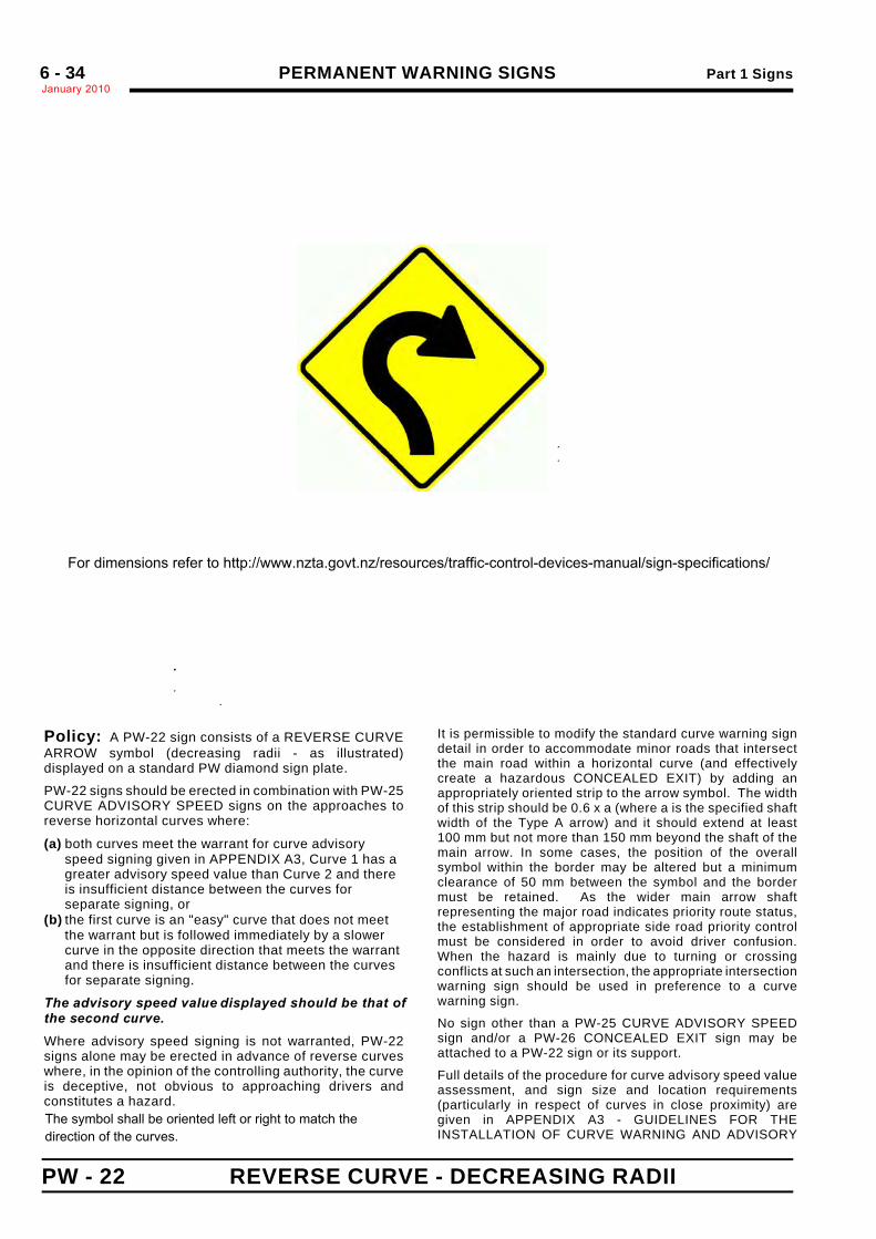
Policy: A PW-22 sign consists of a REVERSE CURVEARROW symbol (decreasing radii - as illustrated)displayed on a standard PW diamond sign plate.
PW-22 signs should be erected in combination with PW-25CURVE ADVISORY SPEED signs on the approaches toreverse horizontal curves where:
(a) both curves meet the warrant for curve advisoryspeed signing given in APPENDIX A3, Curve 1 has agreater advisory speed value than Curve 2 and thereis insufficient distance between the curves forseparate signing, or
(b) the first curve is an "easy" curve that does not meetthe warrant but is followed immediately by a slowercurve in the opposite direction that meets the warrantand there is insufficient distance between the curvesfor separate signing.
The advisory speed value displayed should be that ofthe second curve.
Where advisory speed signing is not warranted, PW-22signs alone may be erected in advance of reverse curveswhere, in the opinion of the controlling authority, the curveis deceptive, not obvious to approaching drivers andconstitutes a hazard.
It is permissible to modify the standard curve warning signdetail in order to accommodate minor roads that intersectthe main road within a horizontal curve (and effectivelycreate a hazardous CONCEALED EXIT) by adding anappropriately oriented strip to the arrow symbol. The widthof this strip should be 0.6 x a (where a is the specified shaftwidth of the Type A arrow) and it should extend at least100 mm but not more than 150 mm beyond the shaft of themain arrow. In some cases, the position of the overallsymbol within the border may be altered but a minimumclearance of 50 mm between the symbol and the bordermust be retained. As the wider main arrow shaftrepresenting the major road indicates priority route status,the establishment of appropriate side road priority controlmust be considered in order to avoid driver confusion.When the hazard is mainly due to turning or crossingconflicts at such an intersection, the appropriate intersectionwarning sign should be used in preference to a curvewarning sign.
No sign other than a PW-25 CURVE ADVISORY SPEEDsign and/or a PW-26 CONCEALED EXIT sign may beattached to a PW-22 sign or its support.
Full details of the procedure for curve advisory speed valueassessment, and sign size and location requirements(particularly in respect of curves in close proximity) aregiven in APPENDIX A3 - GUIDELINES FOR THEINSTALLATION OF CURVE WARNING AND ADVISORY
For dimensions refer to http://www.nzta.govt.nz/resources/traffic-control-devices-manual/sign-specifications/
The symbol shall be oriented left or right to match the direction of the curves.
Part 1 Signs PERMANENT WARNING SIGNSJanuary 2010
6 - 35
REVERSE CURVES (less than 1 km in extent) PW - 23
.
.
.
Sign Size a b c d e f g h600 x 600 310 16 24 635 145 120 68 80
750 x 750 375 20 30 795 180 150 85 100
900 x 900 450 24 36 955 215 180 100 120
1200 x 1200 600 32 48 1270 290 240 136 160
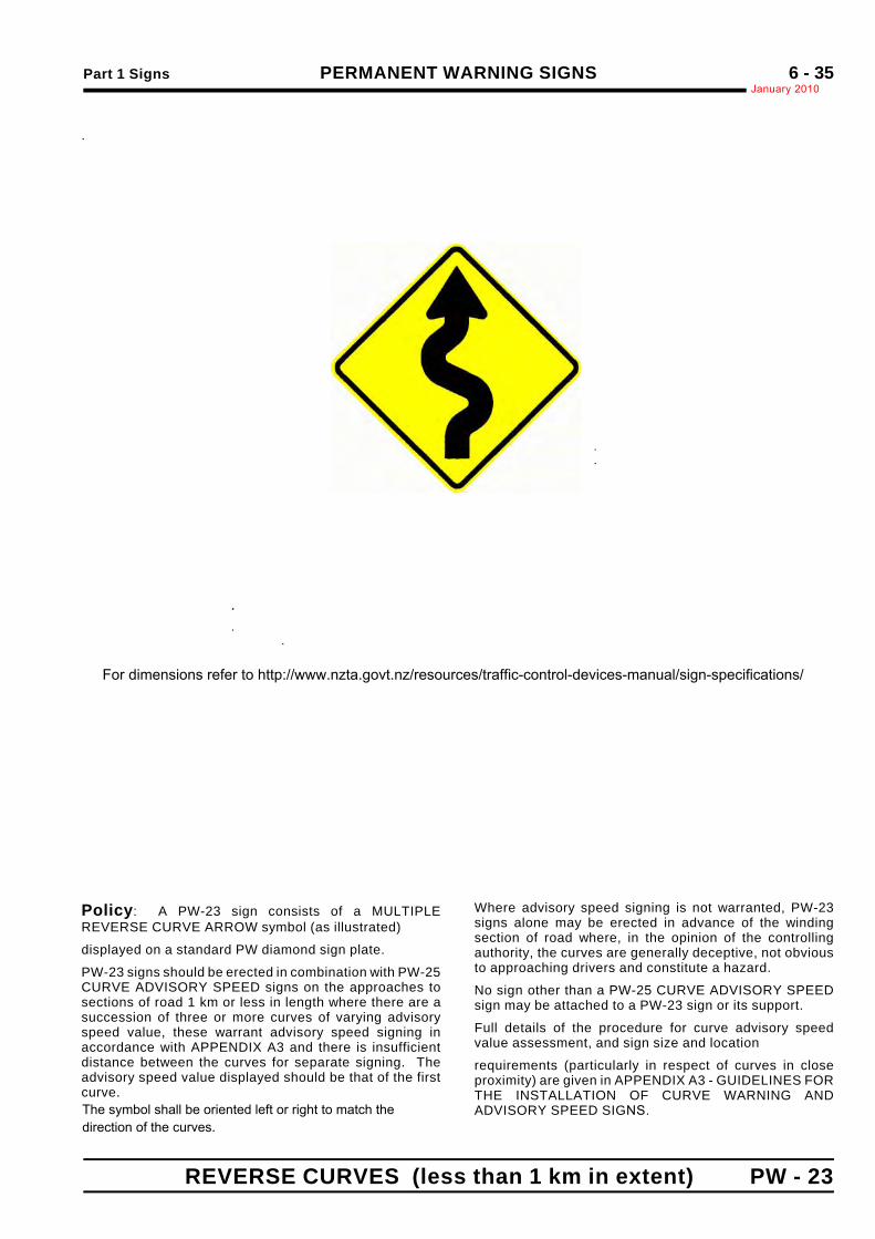
Policy: A PW-23 sign consists of a MULTIPLEREVERSE CURVE ARROW symbol (as illustrated)
displayed on a standard PW diamond sign plate.
PW-23 signs should be erected in combination with PW-25CURVE ADVISORY SPEED signs on the approaches tosections of road 1 km or less in length where there are asuccession of three or more curves of varying advisoryspeed value, these warrant advisory speed signing inaccordance with APPENDIX A3 and there is insufficientdistance between the curves for separate signing. Theadvisory speed value displayed should be that of the firstcurve.
Where advisory speed signing is not warranted, PW-23signs alone may be erected in advance of the windingsection of road where, in the opinion of the controllingauthority, the curves are generally deceptive, not obviousto approaching drivers and constitute a hazard.
No sign other than a PW-25 CURVE ADVISORY SPEEDsign may be attached to a PW-23 sign or its support.
Full details of the procedure for curve advisory speedvalue assessment, and sign size and location
requirements (particularly in respect of curves in closeproximity) are given in APPENDIX A3 - GUIDELINES FORTHE INSTALLATION OF CURVE WARNING ANDADVISORY SPEED SIGNS.
.
. .
For dimensions refer to http://www.nzta.govt.nz/resources/traffic-control-devices-manual/sign-specifications/
The symbol shall be oriented left or right to match the direction of the curves.
PERMANENT WARNING SIGNS Part 1 SignsJanuary 2010*6 - 36
PW - 24 WINDING ROAD NEXT "__" km
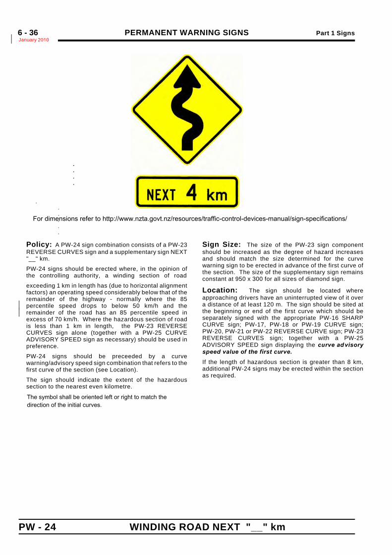
Policy: A PW-24 sign combination consists of a PW-23REVERSE CURVES sign and a supplementary sign NEXT"__" km.
PW-24 signs should be erected where, in the opinion ofthe controlling authority, a winding section of road
exceeding 1 km in length has (due to horizontal alignmentfactors) an operating speed considerably below that of theremainder of the highway - normally where the 85percentile speed drops to below 50 km/h and the*remainder of the road has an 85 percentile speed in*excess of 70 km/h. Where the hazardous section of roadis less than 1 km in length, the PW-23 REVERSECURVES sign alone (together with a PW-25 CURVEADVISORY SPEED sign as necessary) should be used inpreference.
PW-24 signs should be preceeded by a curvewarning/advisory speed sign combination that refers to thefirst curve of the section (see Location).
The sign should indicate the extent of the hazardoussection to the nearest even kilometre.
Sign Size: The size of the PW-23 sign componentshould be increased as the degree of hazard increasesand should match the size determined for the curvewarning sign to be erected in advance of the first curve ofthe section. The size of the supplementary sign remainsconstant at 950 x 300 for all sizes of diamond sign.
Location: The sign should be located whereapproaching drivers have an uninterrupted view of it overa distance of at least 120 m. The sign should be sited atthe beginning or end of the first curve which should beseparately signed with the appropriate PW-16 SHARPCURVE sign; PW-17, PW-18 or PW-19 CURVE sign;PW-20, PW-21 or PW-22 REVERSE CURVE sign; PW-23REVERSE CURVES sign; together with a PW-25ADVISORY SPEED sign displaying the curve ad visoryspeed value of the first curve.
If the length of hazardous section is greater than 8 km,additional PW-24 signs may be erected within the sectionas required.
.
.
.
.*
.. ....
For dimensions refer to http://www.nzta.govt.nz/resources/traffic-control-devices-manual/sign-specifications/
The symbol shall be oriented left or right to match the direction of the initial curves.
Part 1 Signs PERMANENT WARNING SIGNSJanuary 2010
6 - 37
CURVE ADVISORY SPEED (never erected separately) PW - 25
.
.
Size ofCurve WarningDiamond Sign
M
a b600 x 600 600 400 200 E
750 x 750 750 500 250 E
900 x 900 900 600 300 E
1200 x 1200 1200 800 400 E
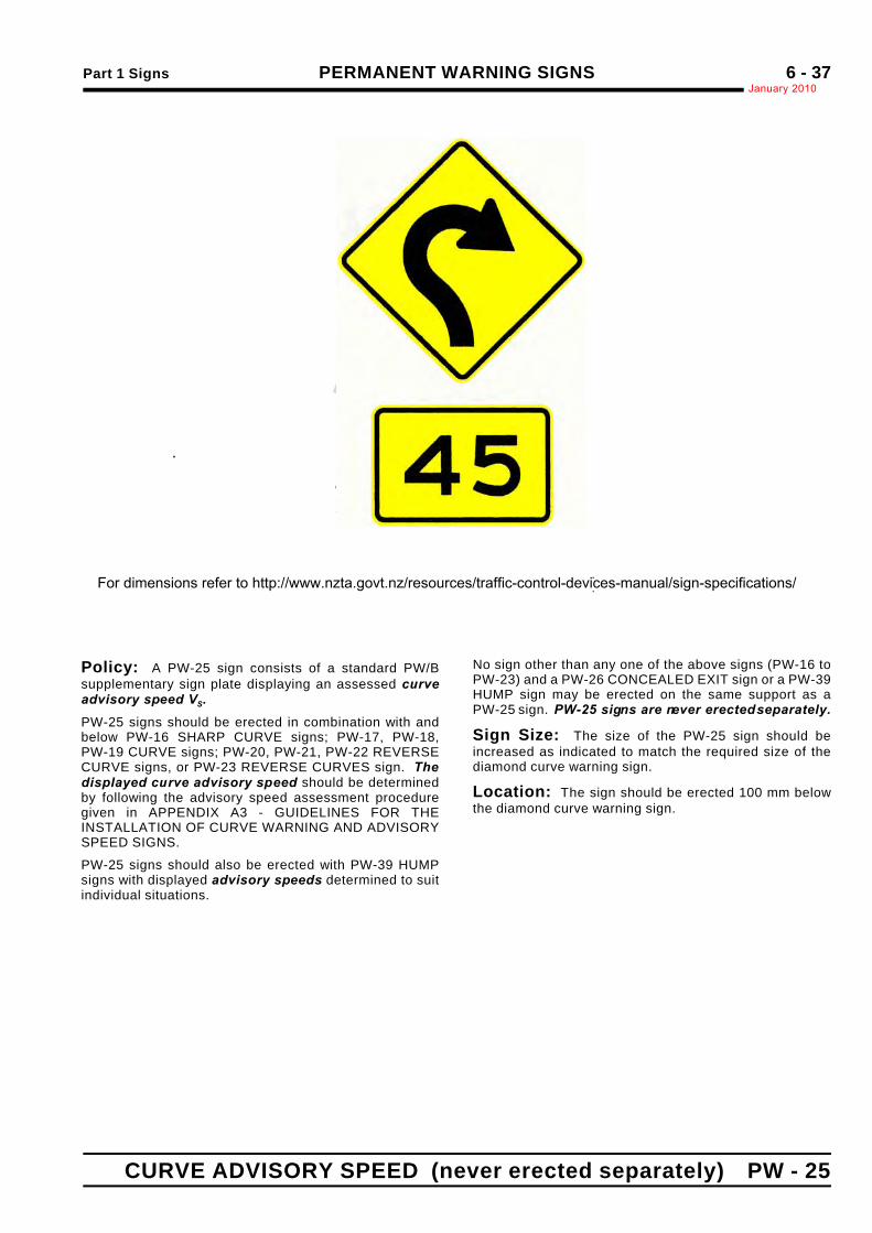
Policy: A PW-25 sign consists of a standard PW/Bsupplementary sign plate displaying an assessed curveadvisory speed VS.
PW-25 signs should be erected in combination with andbelow PW-16 SHARP CURVE signs; PW-17, PW-18,PW-19 CURVE signs; PW-20, PW-21, PW-22 REVERSECURVE signs, or PW-23 REVERSE CURVES sign. Thedisplayed curve advisory speed should be determinedby following the advisory speed assessment proceduregiven in APPENDIX A3 - GUIDELINES FOR THEINSTALLATION OF CURVE WARNING AND ADVISORYSPEED SIGNS.
PW-25 signs should also be erected with PW-39 HUMPsigns with displayed advisory speeds determined to suitindividual situations.
No sign other than any one of the above signs (PW-16 toPW-23) and a PW-26 CONCEALED EXIT sign or a PW-39HUMP sign may be erected on the same support as aPW-25 sign. PW-25 signs are never erected separately.
Sign Size: The size of the PW-25 sign should beincreased as indicated to match the required size of thediamond curve warning sign.
Location: The sign should be erected 100 mm belowthe diamond curve warning sign.
.
For dimensions refer to http://www.nzta.govt.nz/resources/traffic-control-devices-manual/sign-specifications/
PERMANENT WARNING SIGNS Part 1 SignsJanuary 20106 - 37a
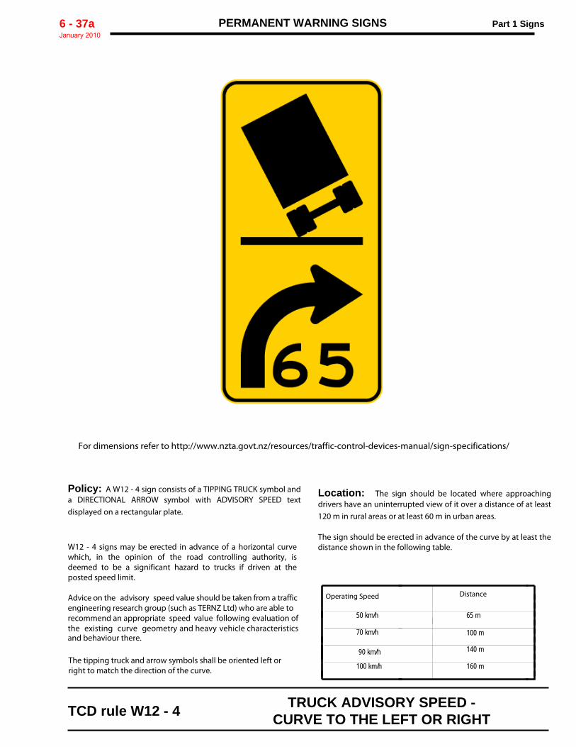
Policy: A W12 - 4 sign consists of a TIPPING TRUCK symbol anda DIRECTIONAL ARROW symbol with ADVISORY SPEED textdisplayed on a rectangular plate.
W12 - 4 signs may be erected in advance of a horizontal curvewhich, in the opinion of the road controlling authority, isdeemed to be a significant hazard to trucks if driven at theposted speed limit. Advice on the advisory speed value should be taken from a trafficengineering research group (such as TERNZ Ltd) who are able torecommend an appropriate speed value following evaluation ofthe existing curve geometry and heavy vehicle characteristics and behaviour there.
Location: The sign should be located where approachingdrivers have an uninterrupted view of it over a distance of at least120 m in rural areas or at least 60 m in urban areas.
The sign should be erected in advance of the curve by at least thedistance shown in the following table.
For dimensions refer to http://www.nzta.govt.nz/resources/traffic-control-devices-manual/sign-specifications/
TCD rule W12 - 4 TRUCK ADVISORY SPEED -CURVE TO THE LEFT OR RIGHT
Operating Speed Distance
50 km/h 65 m
70 km/h 100 m
90 km/h 140 m
160 m100 km/hThe tipping truck and arrow symbols shall be oriented left or right to match the direction of the curve.
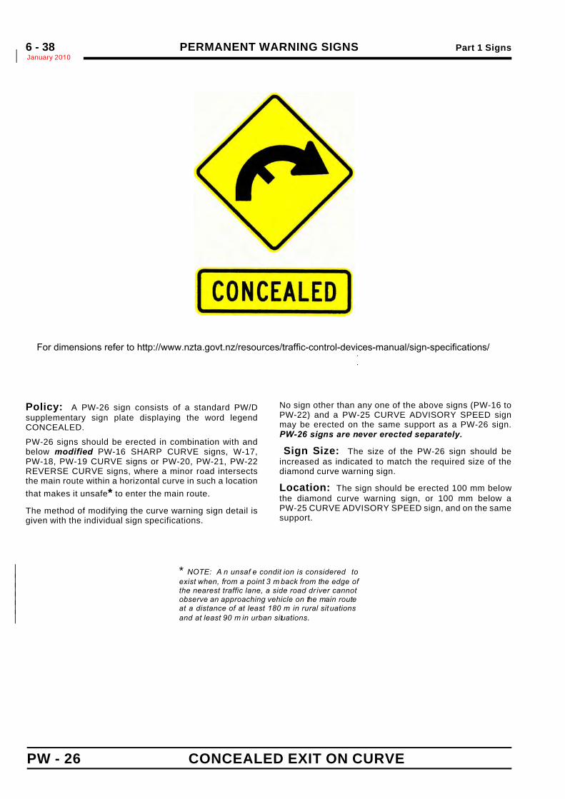
PERMANENT WARNING SIGNS Part 1 SignsJanuary 2010*6 - 38
PW - 26 CONCEALED EXIT ON CURVE
.
.
Size ofCurve WarningDiamond Sign
MSupp
a600 x 600 800
750 x 750 1000
900 x 900 1200 350 940 150 C
1200 x 1200 1600 500 1248 200 C
Policy: A PW-26 sign consists of a standard PW/Dsupplementary sign plate displaying the word legendCONCEALED.
PW-26 signs should be erected in combination with andbelow modified PW-16 SHARP CURVE signs, W-17,PW-18, PW-19 CURVE signs or PW-20, PW-21, PW-22REVERSE CURVE signs, where a minor road intersectsthe main route within a horizontal curve in such a locationthat makes it unsafe* to enter the main route.
The method of modifying the curve warning sign detail isgiven with the individual sign specifications.
No sign other than any one of the above signs (PW-16 toPW-22) and a PW-25 CURVE ADVISORY SPEED signmay be erected on the same support as a PW-26 sign.PW-26 signs are never erected separately.
Sign Size: The size of the PW-26 sign should beincreased as indicated to match the required size of thediamond curve warning sign.
Location: The sign should be erected 100 mm belowthe diamond curve warning sign, or 100 mm below aPW-25 CURVE ADVISORY SPEED sign, and on the samesupport.
* NOTE: A n unsaf e condit ion is considered to*exist when, from a point 3 m back from the edge of*the nearest traffic lane, a side road dr iver cannot*observe an approaching vehicle on the main route*at a distance of at least 180 m in rural situations*and at least 90 m in urban situations.*
SIGN PLATE
For dimensions refer to http://www.nzta.govt.nz/resources/traffic-control-devices-manual/sign-specifications/
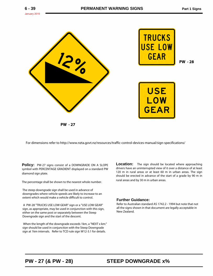
PERMANENT WARNING SIGNS Part 1 SignsJanuary 2010
6 - 39
Policy: PW-27 signs consist of a DOWNGRADE ON A SLOPEsymbol with PERCENTAGE GRADIENT displayed on a standard PWdiamond sign plate.
The percentage shall be shown to the nearest whole number.
Location: The sign should be located where approachingdrivers have an uninterrupted view of it over a distance of at least120 m in rural areas or at least 60 m in urban areas. The signshould be erected in advance of the start of a grade by 90 m inrural areas and by 30 m in urban areas.
For dimensions refer to http://www.nzta.govt.nz/resources/traffic-control-devices-manual/sign-specifications/
PW - 27 (& PW - 28) STEEP DOWNGRADE x%
The steep downgrade sign shall be used in advance ofdowngrades where vehicle speeds are likely to increase to anextent which would make a vehicle difficult to control.
A PW-28 "TRUCKS USE LOW GEAR" sign or a "USE LOW GEAR"sign, as appropriate, may be used in conjunction with this sign,either on the same post or separately between the SteepDowngrade sign and the start of the descent.
When the length of the downgrade exceeds 1km, a "NEXT x km:"sign should be used in conjunction with the Steep Downgradesign at 1km intervals. Refer to TCD rule sign W12-3.1 for details.
PW - 28
PW - 27
Further Guidance:Refer to Australian standard AS 1742.2 - 1994 but note that notall the signs shown in that document are legally acceptable inNew Zealand.
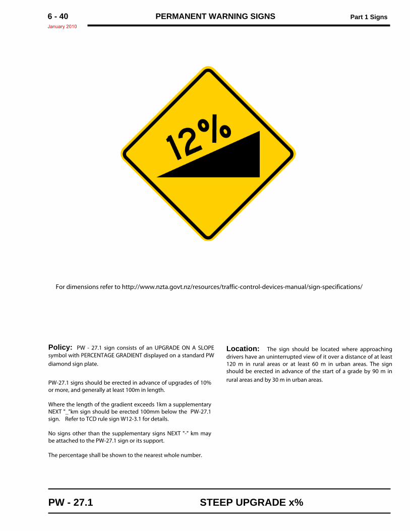
PERMANENT WARNING SIGNS Part 1 SignsJanuary 2010
6 - 40
Policy: PW - 27.1 sign consists of an UPGRADE ON A SLOPEsymbol with PERCENTAGE GRADIENT displayed on a standard PWdiamond sign plate.
PW-27.1 signs should be erected in advance of upgrades of 10%or more, and generally at least 100m in length.
Where the length of the gradient exceeds 1km a supplementaryNEXT "_"km sign should be erected 100mm below the PW-27.1sign. Refer to TCD rule sign W12-3.1 for details.
No signs other than the supplementary signs NEXT "-" km maybe attached to the PW-27.1 sign or its support.
The percentage shall be shown to the nearest whole number.
Location: The sign should be located where approachingdrivers have an uninterrupted view of it over a distance of at least120 m in rural areas or at least 60 m in urban areas. The signshould be erected in advance of the start of a grade by 90 m inrural areas and by 30 m in urban areas.
For dimensions refer to http://www.nzta.govt.nz/resources/traffic-control-devices-manual/sign-specifications/
PW - 27.1 STEEP UPGRADE x%
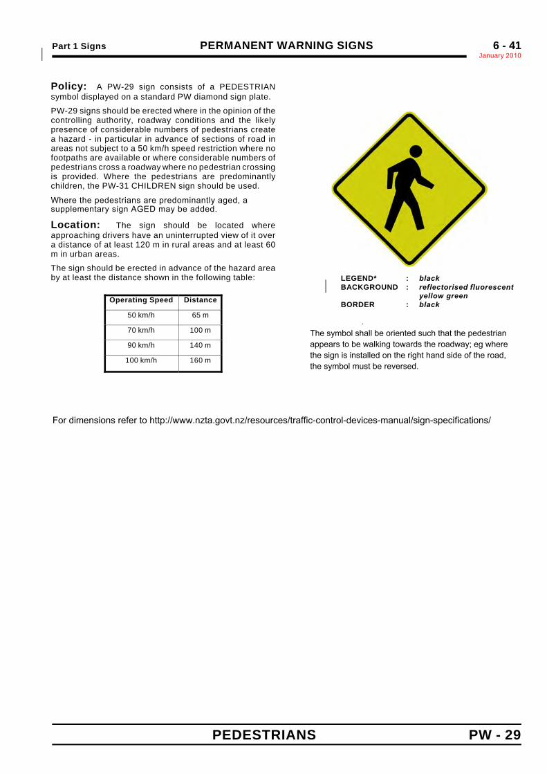
Part 1 Signs PERMANENT WARNING SIGNSJanuary 2010*
6 - 41
PEDESTRIANS PW - 29
Policy: A PW-29 sign consists of a PEDESTRIANsymbol displayed on a standard PW diamond sign plate.
PW-29 signs should be erected where in the opinion of thecontrolling authority, roadway conditions and the likelypresence of considerable numbers of pedestrians createa hazard - in particular in advance of sections of road inareas not subject to a 50 km/h speed restriction where nofootpaths are available or where considerable numbers ofpedestrians cross a roadway where no pedestrian crossingis provided. Where the pedestrians are predominantlychildren, the PW-31 CHILDREN sign should be used.
Where the pedestrians are predominantly aged, asupplementary sign AGED may be added.
Location: The sign should be located whereapproaching drivers have an uninterrupted view of it overa distance of at least 120 m in rural areas and at least 60m in urban areas.
The sign should be erected in advance of the hazard areaby at least the distance shown in the following table:
Operating Speed Distance
50 km/h 65 m
70 km/h 100 m
90 km/h 140 m
100 km/h 160 m
LEGEND* : black *BACKGROUND : reflectorised fluorescent *
yellow green *BORDER : black *
.
.
For dimensions refer to http://www.nzta.govt.nz/resources/traffic-control-devices-manual/sign-specifications/
The symbol shall be oriented such that the pedestrianappears to be walking towards the roadway; eg where the sign is installed on the right hand side of the road,the symbol must be reversed.
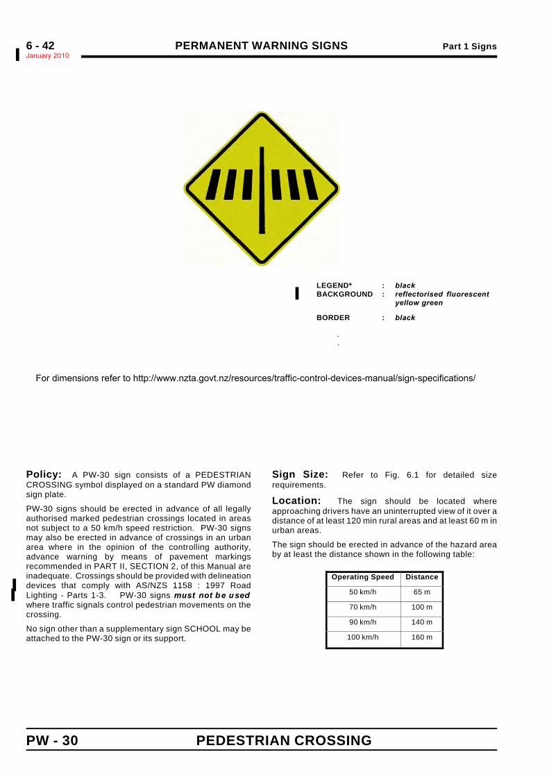
PERMANENT WARNING SIGNS Part 1 SignsJanuary 2010%6 - 42
PW - 30 PEDESTRIAN CROSSING
LEGEND* : black %BACKGROUND : reflectorised fluorescent %
yellow green %
BORDER : black
.
.
Sign Size a b c d e f g h600 x 600 20 30 50 110 60 180 160 120
750 x 750 25 40 60 140 75 225 200 150
900 x 900 30 45 75 165 90 270 240 180
Policy: A PW-30 sign consists of a PEDESTRIANCROSSING symbol displayed on a standard PW diamondsign plate.
PW-30 signs should be erected in advance of all legallyauthorised marked pedestrian crossings located in areasnot subject to a 50 km/h speed restriction. PW-30 signsmay also be erected in advance of crossings in an urbanarea where in the opinion of the controlling authority,advance warning by means of pavement markingsrecommended in PART II, SECTION 2, of this Manual areinadequate. Crossings should be provided with delineationdevices that comply with AS/NZS 1158 : 1997 Road%Lighting - Parts 1-3. PW-30 signs must not be used%where traffic signals control pedestrian movements on thecrossing.
No sign other than a supplementary sign SCHOOL may beattached to the PW-30 sign or its support.
Sign Size: Refer to Fig. 6.1 for detailed sizerequirements.
Location: The sign should be located whereapproaching drivers have an uninterrupted view of it over adistance of at least 120 min rural areas and at least 60 m inurban areas.
The sign should be erected in advance of the hazard areaby at least the distance shown in the following table:
Operating Speed Distance
50 km/h 65 m
70 km/h 100 m
90 km/h 140 m
100 km/h 160 m
For dimensions refer to http://www.nzta.govt.nz/resources/traffic-control-devices-manual/sign-specifications/
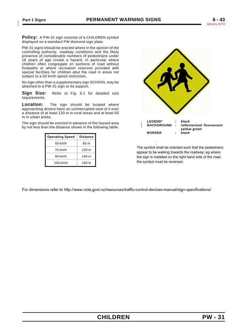
Part 1 Signs PERMANENT WARNING SIGNSJanuary 2010*
6 - 43
CHILDREN PW - 31
Sign Size a600 × 600 40750 × 750 50900 × 900 60
Policy: A PW-31 sign consists of a CHILDREN symboldisplayed on a standard PW diamond sign plate.
PW-31 signs should be erected where in the opinion of thecontrolling authority, roadway conditions and the likelypresence of considerable numbers of pedestrians under16 years of age create a hazard. In particular wherechildren often congregate on sections of road withoutfootpaths or where recreation reserves provided withspecial facilities for children abut the road in areas notsubject to a 50 km/h speed restriction.
No sign other than a supplementary sign SCHOOL may beattached to a PW-31 sign or its support.
Sign Size: Refer to Fig. 6.1 for detailed sizerequirements.
Location: The sign should be located whereapproaching drivers have an uninterrupted view of it overa distance of at least 120 m in rural areas and at least 60m in urban areas.
The sign should be erected in advance of the hazard areaby not less than the distance shown in the following table:
Operating Speed Distance
50 km/h 65 m
70 km/h 100 m
90 km/h 140 m
100 km/h 160 m
LEGEND* : black BACKGROUND : reflectorised fluorescent *
yellow green *BORDER : black *
.
.
For dimensions refer to http://www.nzta.govt.nz/resources/traffic-control-devices-manual/sign-specifications/
The symbol shall be oriented such that the pedestriansappear to be walking towards the roadway; eg where the sign is installed on the right hand side of the road,the symbol must be reversed.
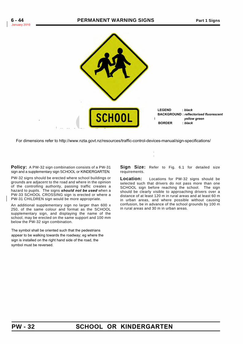
PERMANENT WARNING SIGNS Part 1 SignsJanuary 2010*6 - 44
PW - 32 S CHOOL OR KINDERGARTEN
.
.
.
Size of PW-31Diamond Sign
Matching Supplementary Sign
a b c Letters
600 x 600 800 250 629 100 C
750 x 750 1000 300 788 125 C
900 x 900 1200 350 940 150 C
Policy: A PW-32 sign combination consists of a PW-31sign and a supplementary sign SCHOOL or KINDERGARTEN.
PW-32 signs should be erected where school buildings orgrounds are adjacent to the road and where in the opinionof the controlling authority, passing traffic creates ahazard to pupils. The signs should not be used when aPW-33 SCHOOL CROSSING sign is erected or where aPW-31 CHILDREN sign would be more appropriate.*
An additional supplementary sign no larger than 600 x250, of the same colour and format as the SCHOOLsupplementary sign, and displaying the name of theschool, may be erected on the same support and 100 mmbelow the PW-32 sign combination.
Sign Size: Refer to Fig. 6.1 for detailed sizerequirements.
Location: Locations for PW-32 signs should beselected such that drivers do not pass more than oneSCHOOL sign before reaching the school. The signshould be clearly visible to approaching drivers over adistance of at least 120 m in rural areas and at least 60 min urban areas, and where possible without causingconfusion, be in advance of the school grounds by 100 min rural areas and 30 m in urban areas.
For dimensions refer to http://www.nzta.govt.nz/resources/traffic-control-devices-manual/sign-specifications/
LEGEND : black BACKGROUND : reflectorised fluorescent
I yellow green BORDER : black
The symbol shall be oriented such that the pedestriansappear to be walking towards the roadway; eg where the sign is installed on the right hand side of the road, the symbol must be reversed.
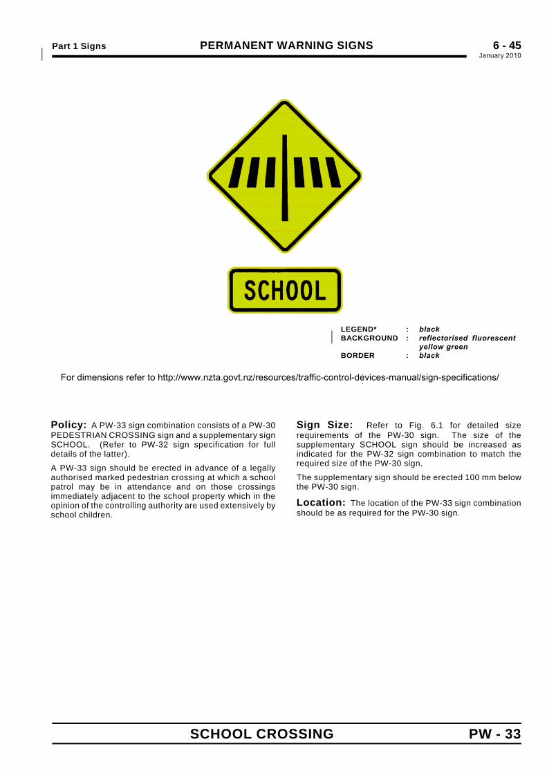
Part 1 Signs PERMANENT WARNING SIGNSJanuary 2010*
6 - 45
SCHOOL CROSSING PW - 33
*
*
*
*
*
*
*
*
*
*
*
*
*
LEGEND* : black *BACKGROUND : reflectorised fluorescent *
yellow green *BORDER : black *
.
.
Policy: A PW-33 sign combination consists of a PW-30PEDESTRIAN CROSSING sign and a supplementary signSCHOOL. (Refer to PW-32 sign specification for fulldetails of the latter).
A PW-33 sign should be erected in advance of a legallyauthorised marked pedestrian crossing at which a schoolpatrol may be in attendance and on those crossingsimmediately adjacent to the school property which in theopinion of the controlling authority are used extensively byschool children.
Sign Size: Refer to Fig. 6.1 for detailed sizerequirements of the PW-30 sign. The size of thesupplementary SCHOOL sign should be increased asindicated for the PW-32 sign combination to match therequired size of the PW-30 sign.
The supplementary sign should be erected 100 mm belowthe PW-30 sign.
Location: The location of the PW-33 sign combinationshould be as required for the PW-30 sign.
For dimensions refer to http://www.nzta.govt.nz/resources/traffic-control-devices-manual/sign-specifications/
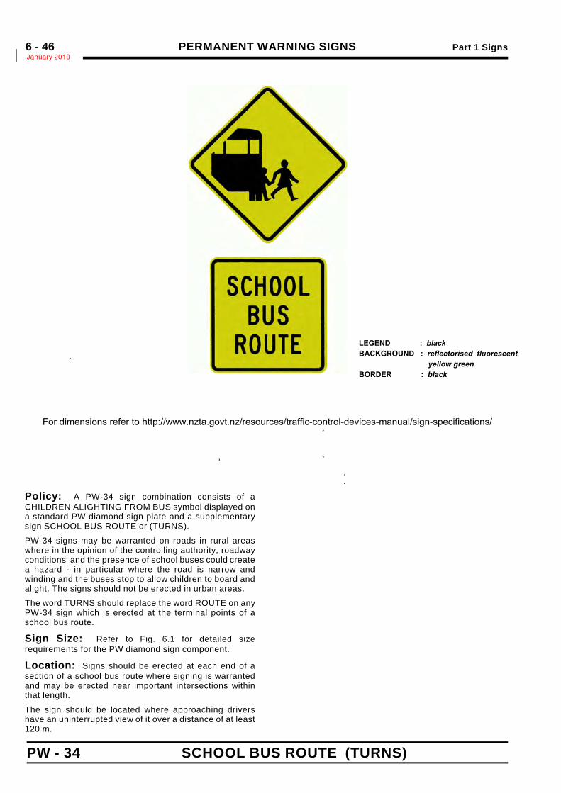
PERMANENT WARNING SIGNS Part 1 SignsJanuary 2010*6 - 46
PW - 34 SCHOOL BUS ROUTE (TURNS)
Policy: A PW-34 sign combination consists of aCHILDREN ALIGHTING FROM BUS symbol displayed ona standard PW diamond sign plate and a supplementarysign SCHOOL BUS ROUTE or (TURNS).
PW-34 signs may be warranted on roads in rural areaswhere in the opinion of the controlling authority, roadwayconditions and the presence of school buses could createa hazard - in particular where the road is narrow andwinding and the buses stop to allow children to board andalight. The signs should not be erected in urban areas.
The word TURNS should replace the word ROUTE on anyPW-34 sign which is erected at the terminal points of aschool bus route.
Sign Size: Refer to Fig. 6.1 for detailed sizerequirements for the PW diamond sign component.
Location: Signs should be erected at each end of asection of a school bus route where signing is warrantedand may be erected near important intersections withinthat length.
The sign should be located where approaching drivershave an uninterrupted view of it over a distance of at least120 m.
*
*
*
*
*
*
*
*
*
*
*
*
*
*
*
*
*
*
*
*
*
*
. *
. * *
. *
.
.
.
PW DiamondSign Size
Matching Supplementary SignSCHOOL BUS ROUTE (TURNS)
a b c d e f g 1 g 2 Letters
750 ×750 50 750 190 65 530 259 425 437 125 C
900 × 900 60 900 225 75 636 310 510 525 150 C
LEGEND : black BACKGROUND : reflectorised fluorescent yellow green BORDER : black
For dimensions refer to http://www.nzta.govt.nz/resources/traffic-control-devices-manual/sign-specifications/
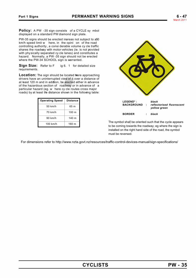
Part 1 Signs PERMANENT WARNING SIGNS March 2011%
6 - 47
CYCLISTS PW - 35
Policy: A PW -35 sign consists of a CYCLE sy mboldisplayed on a standard PW diamond sign plate.
PW-35 signs should be erected in areas not subject to a 50 km/h speed limit w here, in the opini on of the roadcontrolling authority , a consi derable volume cy cle trafficshares the roadway with motor vehicles (ie. is not providedwith physically separated cy cle lanes) and constitutes ahazard. Normally, a PW -35 sign should not be erectedwhere the PW-34 SCHOOL sign is warranted.
Sign Size: Refer to F ig 6. 1 for detailed sizerequirements.
Location: The sign should be located where approachingdrivers have an uninterrupted view of it over a distance ofat least 120 m and in addition, be erected either in advanceof the hazardous section of roadway or in advance of aparticular hazard (eg. w here cy cle routes cross majorroads) by at least the distance shown in the following table:
Operating Speed Distance
50 km/h 65 m
70 km/h 100 m
90 km/h 140 m
100 km/h 160 m
% %% % % % % % % % % % % %
LEGEND* : black %BACKGROUND : reflectorised fluorescent %
yellow green %
BORDER : black % %
.
.
Sign Size a750 x 750 50
900 x 900 60
For dimensions refer to http://www.nzta.govt.nz/resources/traffic-control-devices-manual/sign-specifications/
The symbol shall be oriented such that the cycle appears to be coming towards the roadway; eg where the sign is installed on the right hand side of the road, the symbol must be reversed.
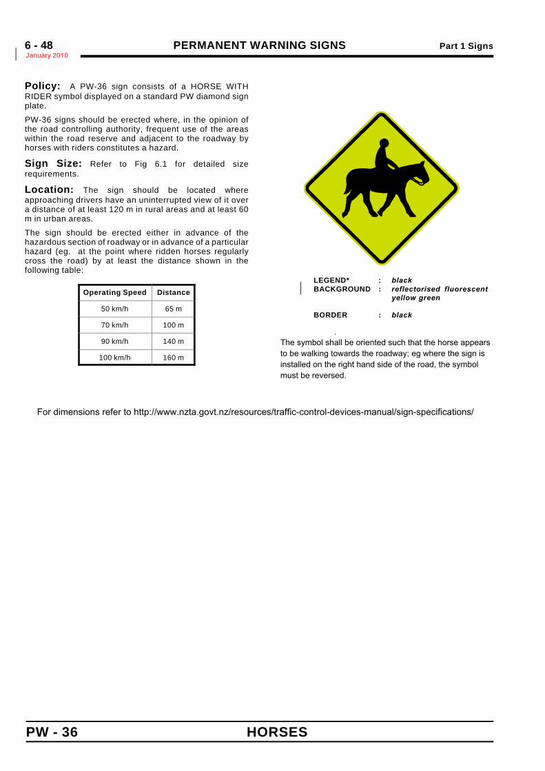
PERMANENT WARNING SIGNS Part 1 SignsJanuary 2010*6 - 48
PW - 36 HORSES
Policy: A PW-36 sign consists of a HORSE WITHRIDER symbol displayed on a standard PW diamond signplate.
PW-36 signs should be erected where, in the opinion ofthe road controlling authority, frequent use of the areaswithin the road reserve and adjacent to the roadway byhorses with riders constitutes a hazard.
Sign Size: Refer to Fig 6.1 for detailed sizerequirements.
Location: The sign should be located whereapproaching drivers have an uninterrupted view of it overa distance of at least 120 m in rural areas and at least 60m in urban areas.
The sign should be erected either in advance of thehazardous section of roadway or in advance of a particularhazard (eg. at the point where ridden horses regularlycross the road) by at least the distance shown in thefollowing table:
Operating Speed Distance
50 km/h 65 m
70 km/h 100 m
90 km/h 140 m
100 km/h 160 m
*
*
*
*
*
*
*
*
*
*
*
*
*
*
LEGEND* : black *BACKGROUND : reflectorised fluorescent *
yellow green * *
BORDER : black *
.
..
Sign Size a600 x 600 40
750 x 750 50
900 x 900 60
For dimensions refer to http://www.nzta.govt.nz/resources/traffic-control-devices-manual/sign-specifications/
The symbol shall be oriented such that the horse appears to be walking towards the roadway; eg where the sign is installed on the right hand side of the road, the symbol must be reversed.

PERMANENT WARNING SIGNS Part 1 SignsNovember 2010
6 - 49
Policy: This sign consists of a WILD HORSE symbol displayed ona standard PW diamond sign plate.
These signs may be erected where, in the opinion of the roadcontrolling authority, the presence of wild horses within the roadreserve and adjacent to the roadway constitutes a hazard.
Location: The sign should be located where approachingdrivers have an uninterrupted view of it over a distance of at least120 m in rural areas and at least 60 m in urban areas.
The sign should be erected in advance of the hazardous section ofroadway by at least the distance shown in the following table.
For dimensions refer to http://www.nzta.govt.nz/resources/traffic-control-devices-manual/sign-specifications/
WILD HORSES
Operating Speed Distance
50 km/h 65 m
70 km/h 100 m
90 km/h 140 m
160 m100 km/h
The symbol shall be oriented such that the horse appears to be coming towards the roadway; eg where the sign is installed on the right hand side of the road, the symbol must be reversed.
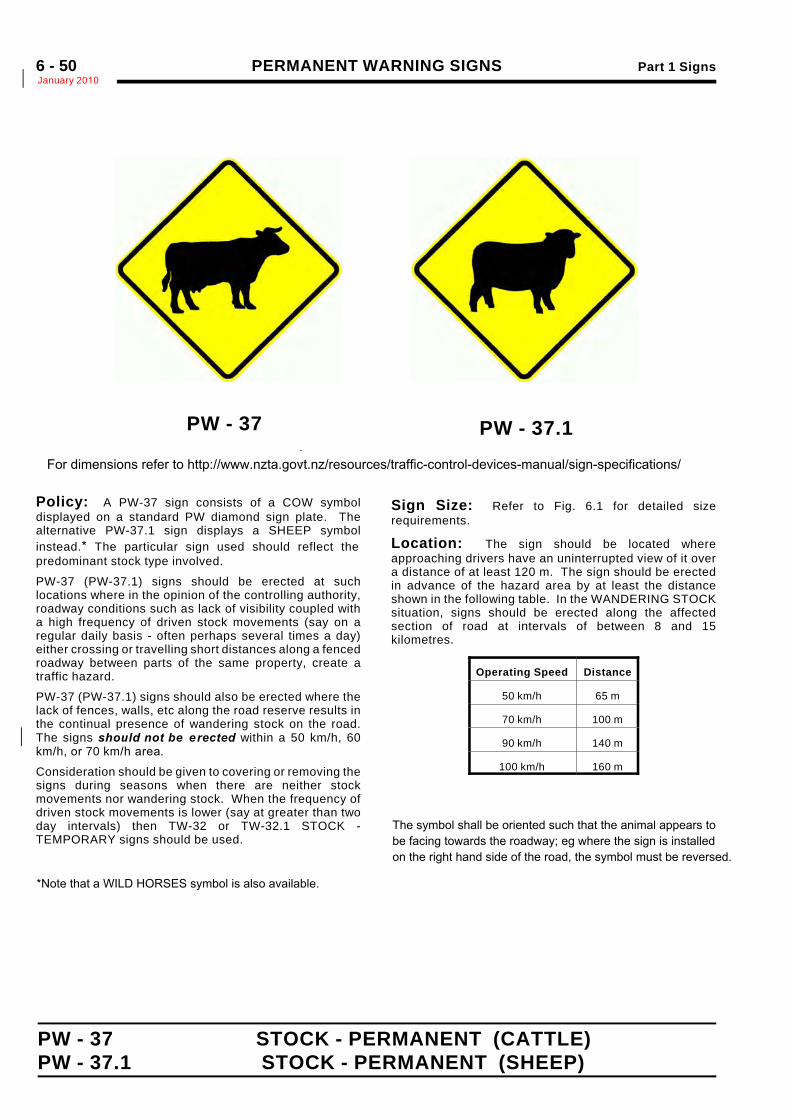
PERMANENT WARNING SIGNS Part 1 SignsJanuary 2010*6 - 50
PW - 37 STOCK - PERMANENT (CATTLE)PW - 37.1 STOCK - PERMANENT (SHEEP)
PW - 37..
Policy: A PW-37 sign consists of a COW symboldisplayed on a standard PW diamond sign plate. Thealternative PW-37.1 sign displays a SHEEP symbolinstead.* The particular sign used should reflect thepredominant stock type involved.
PW-37 (PW-37.1) signs should be erected at suchlocations where in the opinion of the controlling authority,roadway conditions such as lack of visibility coupled witha high frequency of driven stock movements (say on aregular daily basis - often perhaps several times a day)either crossing or travelling short distances along a fencedroadway between parts of the same property, create atraffic hazard.
PW-37 (PW-37.1) signs should also be erected where thelack of fences, walls, etc along the road reserve results inthe continual presence of wandering stock on the road.The signs should not be erected within a 50 km/h, 60*km/h, or 70 km/h area.*
Consideration should be given to covering or removing thesigns during seasons when there are neither stockmovements nor wandering stock. When the frequency ofdriven stock movements is lower (say at greater than twoday intervals) then TW-32 or TW-32.1 STOCK -TEMPORARY signs should be used.
Sign Size: Refer to Fig. 6.1 for detailed sizerequirements.
Location: The sign should be located whereapproaching drivers have an uninterrupted view of it overa distance of at least 120 m. The sign should be erectedin advance of the hazard area by at least the distanceshown in the following table. In the WANDERING STOCKsituation, signs should be erected along the affectedsection of road at intervals of between 8 and 15kilometres.
Operating Speed Distance
50 km/h 65 m
70 km/h 100 m
90 km/h 140 m
100 km/h 160 m
PW - 37.1 For dimensions refer to http://www.nzta.govt.nz/resources/traffic-control-devices-manual/sign-specifications/
*Note that a WILD HORSES symbol is also available.
The symbol shall be oriented such that the animal appears to be facing towards the roadway; eg where the sign is installed on the right hand side of the road, the symbol must be reversed.
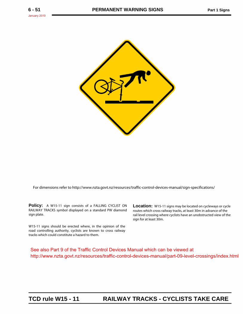
PERMANENT WARNING SIGNS Part 1 SignsJanuary 2010
6 - 51
Policy: A W15-11 sign consists of a FALLING CYCLIST ONRAILWAY TRACKS symbol displayed on a standard PW diamondsign plate.
W15-11 signs should be erected where, in the opinion of theroad controlling authority, cyclists are known to cross railwaytracks which could constitute a hazard to them.
For dimensions refer to http://www.nzta.govt.nz/resources/traffic-control-devices-manual/sign-specifications/
TCD rule W15 - 11 RAILWAY TRACKS - CYCLISTS TAKE CARE
Location: W15-11 signs may be located on cycleways or cycleroutes which cross railway tracks, at least 30m in advance of therail level crossing where cyclists have an unobstructed view of thesign for at least 30m.
See also Part 9 of the Traffic Control Devices Manual which can be viewed athttp://www.nzta.govt.nz/resources/traffic-control-devices-manual/part-09-level-crossings/index.html
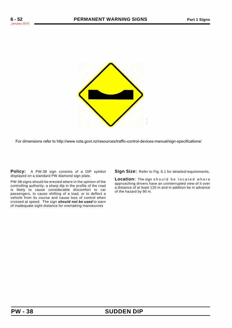
PERMANENT WARNING SIGNS Part 1 SignsJanuary 20106 - 52
PW - 38 SUDDEN DIP
.
.
Sign Size a b c600 x 600 560 60 260
750 x 750 700 75 325
900 x 900 840 90 390
Policy: A PW-38 sign consists of a DIP symboldisplayed on a standard PW diamond sign plate.
PW-38 signs should be erected where in the opinion of thecontrolling authority, a sharp dip in the profile of the roadis likely to cause considerable discomfort to carpassengers, to cause shifting of a load, or to deflect avehicle from its course and cause loss of control whencrossed at speed. The sign should not be used to warnof inadequate sight distance for overtaking manoeuvres
Sign Size: Refer to Fig. 6.1 for detailed requirements.
Location: The sign s h o u l d b e l o c a t e d w h e r eapproaching drivers have an uninterrupted view of it overa distance of at least 120 m and in addition be in advanceof the hazard by 90 m.
For dimensions refer to http://www.nzta.govt.nz/resources/traffic-control-devices-manual/sign-specifications/
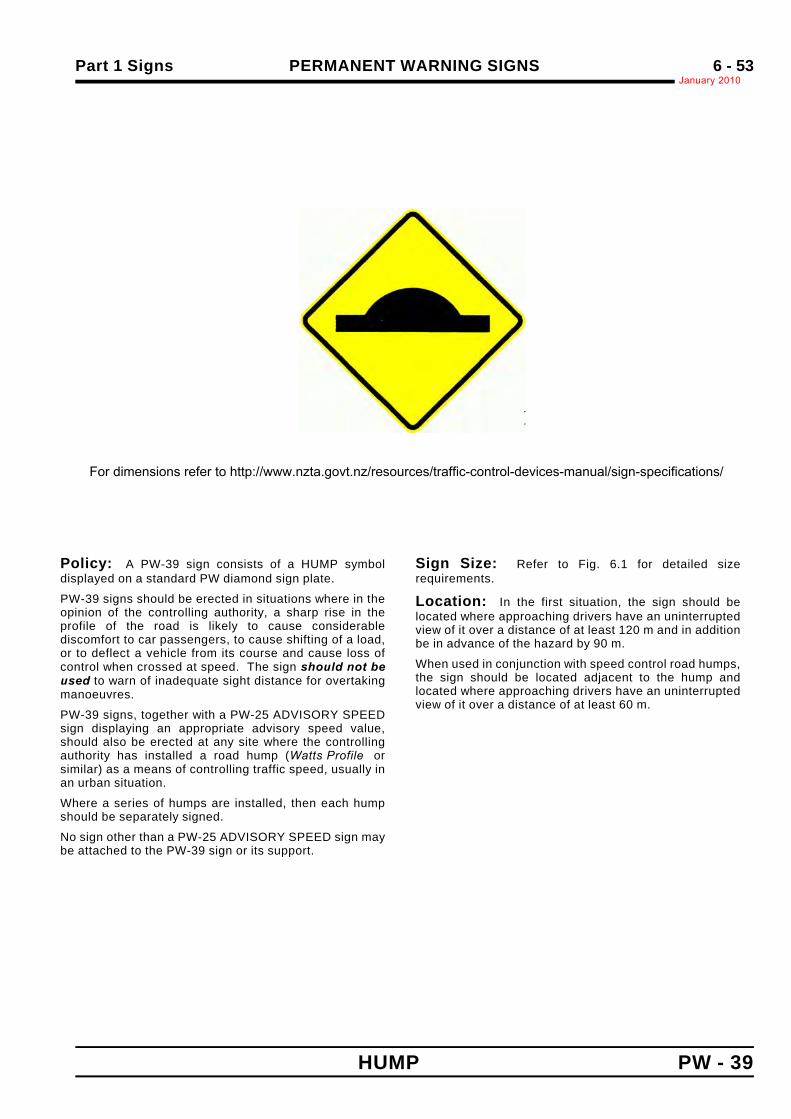
Part 1 Signs PERMANENT WARNING SIGNSJanuary 2010
6 - 53
HUMP PW - 39
.
.
Sign Size a b c d e600 x 600 40 40 560 200 60
750 x 750 50 50 700 250 75
900 x 900 60 60 840 300 90
Policy: A PW-39 sign consists of a HUMP symboldisplayed on a standard PW diamond sign plate.
PW-39 signs should be erected in situations where in theopinion of the controlling authority, a sharp rise in theprofile of the road is likely to cause considerablediscomfort to car passengers, to cause shifting of a load,or to deflect a vehicle from its course and cause loss ofcontrol when crossed at speed. The sign should not beused to warn of inadequate sight distance for overtakingmanoeuvres.
PW-39 signs, together with a PW-25 ADVISORY SPEEDsign displaying an appropriate advisory speed value,should also be erected at any site where the controllingauthority has installed a road hump (Watts Profile orsimilar) as a means of controlling traffic speed, usually inan urban situation.
Where a series of humps are installed, then each humpshould be separately signed.
No sign other than a PW-25 ADVISORY SPEED sign maybe attached to the PW-39 sign or its support.
Sign Size: Refer to Fig. 6.1 for detailed sizerequirements.
Location: In the first situation, the sign should belocated where approaching drivers have an uninterruptedview of it over a distance of at least 120 m and in additionbe in advance of the hazard by 90 m.
When used in conjunction with speed control road humps,the sign should be located adjacent to the hump andlocated where approaching drivers have an uninterruptedview of it over a distance of at least 60 m.
For dimensions refer to http://www.nzta.govt.nz/resources/traffic-control-devices-manual/sign-specifications/
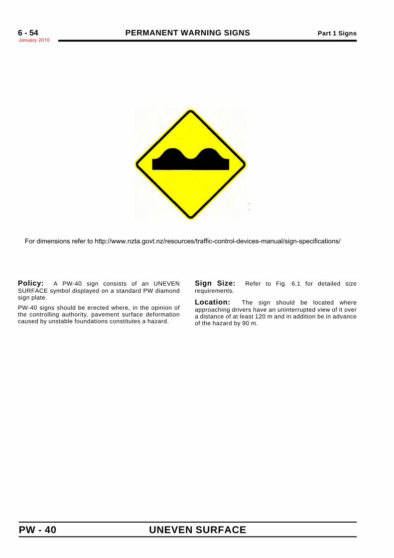
PERMANENT WARNING SIGNS Part 1 SignsJanuary 20106 - 54
PW - 40 UNEVEN SURFACE
.
.
Sign Size a b c d e600 x 600 560 80 60 100 130
750 x 750 700 100 75 125 165
900 x 900 840 120 90 150 195
Policy: A PW-40 sign consists of an UNEVENSURFACE symbol displayed on a standard PW diamondsign plate.
PW-40 signs should be erected where, in the opinion ofthe controlling authority, pavement surface deformationcaused by unstable foundations constitutes a hazard.
Sign Size: Refer to Fig. 6.1 for detailed sizerequirements.
Location: The sign should be located whereapproaching drivers have an uninterrupted view of it overa distance of at least 120 m and in addition be in advanceof the hazard by 90 m.
For dimensions refer to http://www.nzta.govt.nz/resources/traffic-control-devices-manual/sign-specifications/
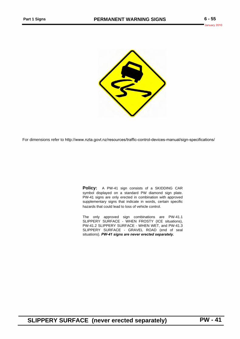
Part 1 Signs PERMANENT WARNING SIGNSJanuary 2010
6 - 55
SLIPPERY SURFACE (never erected separately) PW - 41
Sign Size a750 x 750 50
900 x 900 60
Policy: A PW-41 sign consists of a SKIDDING CARsymbol displayed on a standard PW diamond sign plate.PW-41 signs are only erected in combination with approvedsupplementary signs that indicate in words, certain specifichazards that could lead to loss of vehicle control.
The only approved sign combinations are PW-41.1SLIPPERY SURFACE - WHEN FROSTY (ICE situations),PW-41.2 SLIPPERY SURFACE - WHEN WET, and PW-41.3SLIPPERY SURFACE - GRAVEL ROAD (end of sealsituations). PW-41 signs are never erected separately.
For dimensions refer to http://www.nzta.govt.nz/resources/traffic-control-devices-manual/sign-specifications/
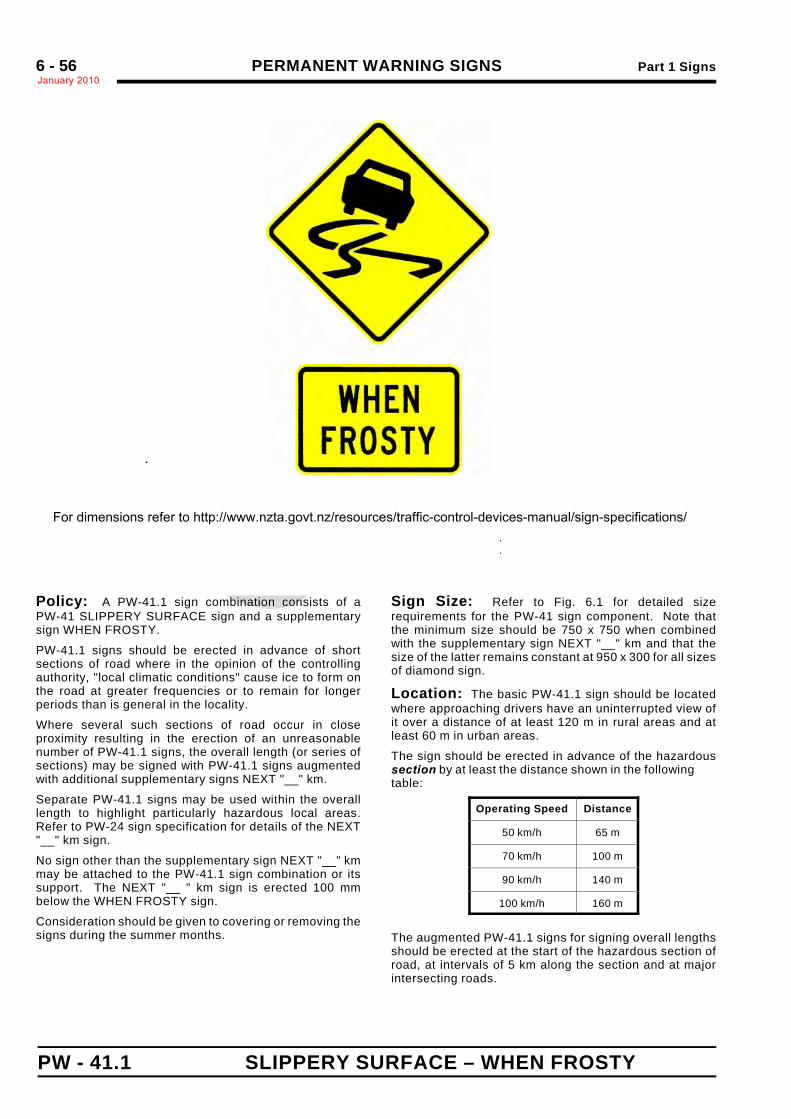
PERMANENT WARNING SIGNS Part 1 SignsJanuary 20106 - 56
PW - 41.1 SLIPPERY SURFACE – WHEN FROSTY
.
.
.
Sign Size a b c d e600 x 600 560 80 60 100 130
750 x 750 700 100 75 125 165
900 x 900 840 120 90 150 195
Policy: A PW-41.1 sign combination consists of aPW-41 SLIPPERY SURFACE sign and a supplementarysign WHEN FROSTY.
PW-41.1 signs should be erected in advance of shortsections of road where in the opinion of the controllingauthority, "local climatic conditions" cause ice to form onthe road at greater frequencies or to remain for longerperiods than is general in the locality.
Where several such sections of road occur in closeproximity resulting in the erection of an unreasonablenumber of PW-41.1 signs, the overall length (or series ofsections) may be signed with PW-41.1 signs augmentedwith additional supplementary signs NEXT "__" km.
Separate PW-41.1 signs may be used within the overalllength to highlight particularly hazardous local areas.Refer to PW-24 sign specification for details of the NEXT"__" km sign.
No sign other than the supplementary sign NEXT "__” kmmay be attached to the PW-41.1 sign combination or itssupport. The NEXT "__ " km sign is erected 100 mmbelow the WHEN FROSTY sign.
Consideration should be given to covering or removing thesigns during the summer months.
Sign Size: Refer to Fig. 6.1 for detailed sizerequirements for the PW-41 sign component. Note thatthe minimum size should be 750 x 750 when combinedwith the supplementary sign NEXT "__" km and that thesize of the latter remains constant at 950 x 300 for all sizesof diamond sign.
Location: The basic PW-41.1 sign should be locatedwhere approaching drivers have an uninterrupted view ofit over a distance of at least 120 m in rural areas and atleast 60 m in urban areas.
The sign should be erected in advance of the hazardoussection by at least the distance shown in the followingtable:
Operating Speed Distance
50 km/h 65 m
70 km/h 100 m
90 km/h 140 m
100 km/h 160 m
The augmented PW-41.1 signs for signing overall lengthsshould be erected at the start of the hazardous section ofroad, at intervals of 5 km along the section and at majorintersecting roads.
For dimensions refer to http://www.nzta.govt.nz/resources/traffic-control-devices-manual/sign-specifications/
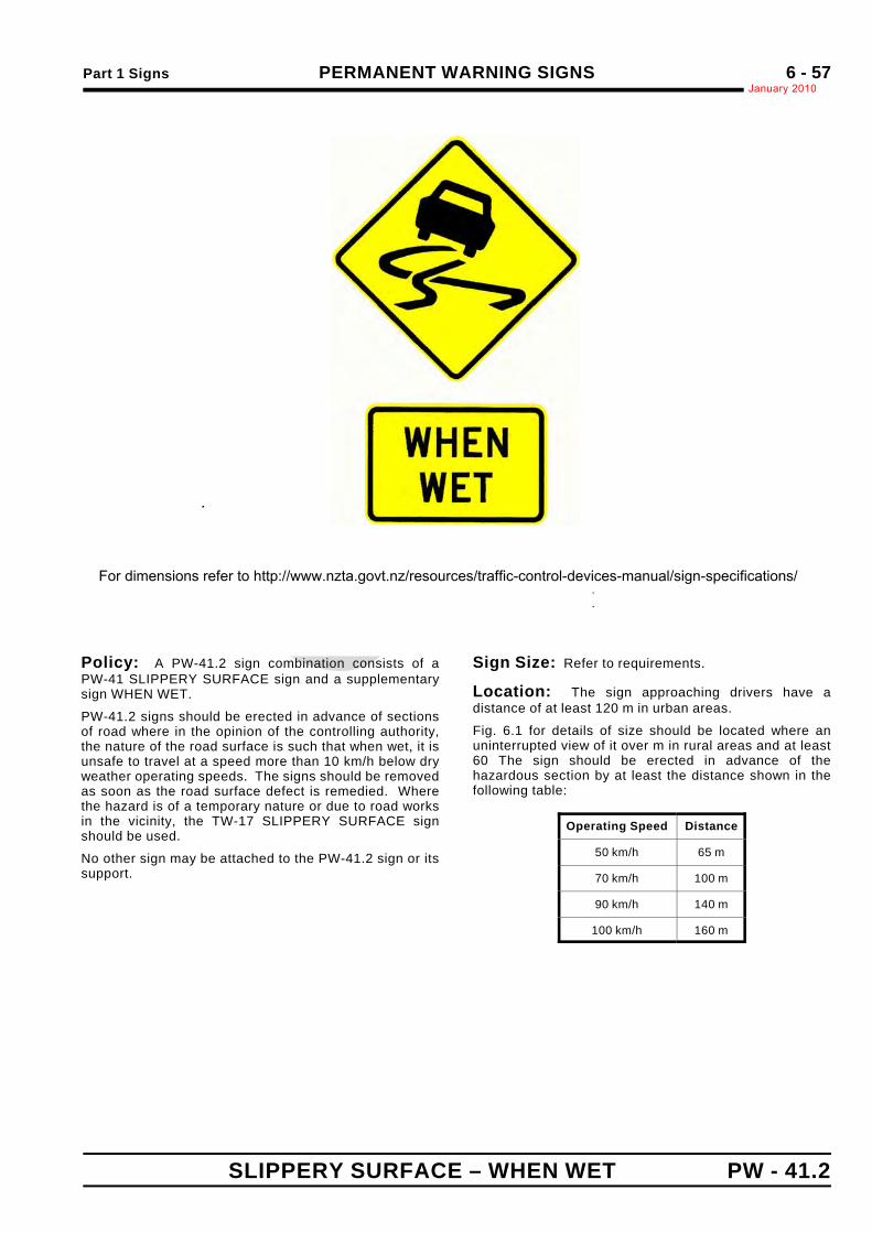
Part 1 Signs PERMANENT WARNING SIGNSJanuary 2010
6 - 57
SLIPPERY SURFACE – WHEN WET PW - 41.2
.
.
.
Sign Size a b c d e600 x 600 560 80 60 100 130
750 x 750 700 100 75 125 165
900 x 900 840 120 90 150 195
Policy: A PW-41.2 sign combination consists of aPW-41 SLIPPERY SURFACE sign and a supplementarysign WHEN WET.
PW-41.2 signs should be erected in advance of sectionsof road where in the opinion of the controlling authority,the nature of the road surface is such that when wet, it isunsafe to travel at a speed more than 10 km/h below dryweather operating speeds. The signs should be removedas soon as the road surface defect is remedied. Wherethe hazard is of a temporary nature or due to road worksin the vicinity, the TW-17 SLIPPERY SURFACE signshould be used.
No other sign may be attached to the PW-41.2 sign or itssupport.
Sign Size: Refer to requirements.
Location: The sign approaching drivers have adistance of at least 120 m in urban areas.
Fig. 6.1 for details of size should be located where anuninterrupted view of it over m in rural areas and at least60 The sign should be erected in advance of thehazardous section by at least the distance shown in thefollowing table:
Operating Speed Distance
50 km/h 65 m
70 km/h 100 m
90 km/h 140 m
100 km/h 160 m
For dimensions refer to http://www.nzta.govt.nz/resources/traffic-control-devices-manual/sign-specifications/
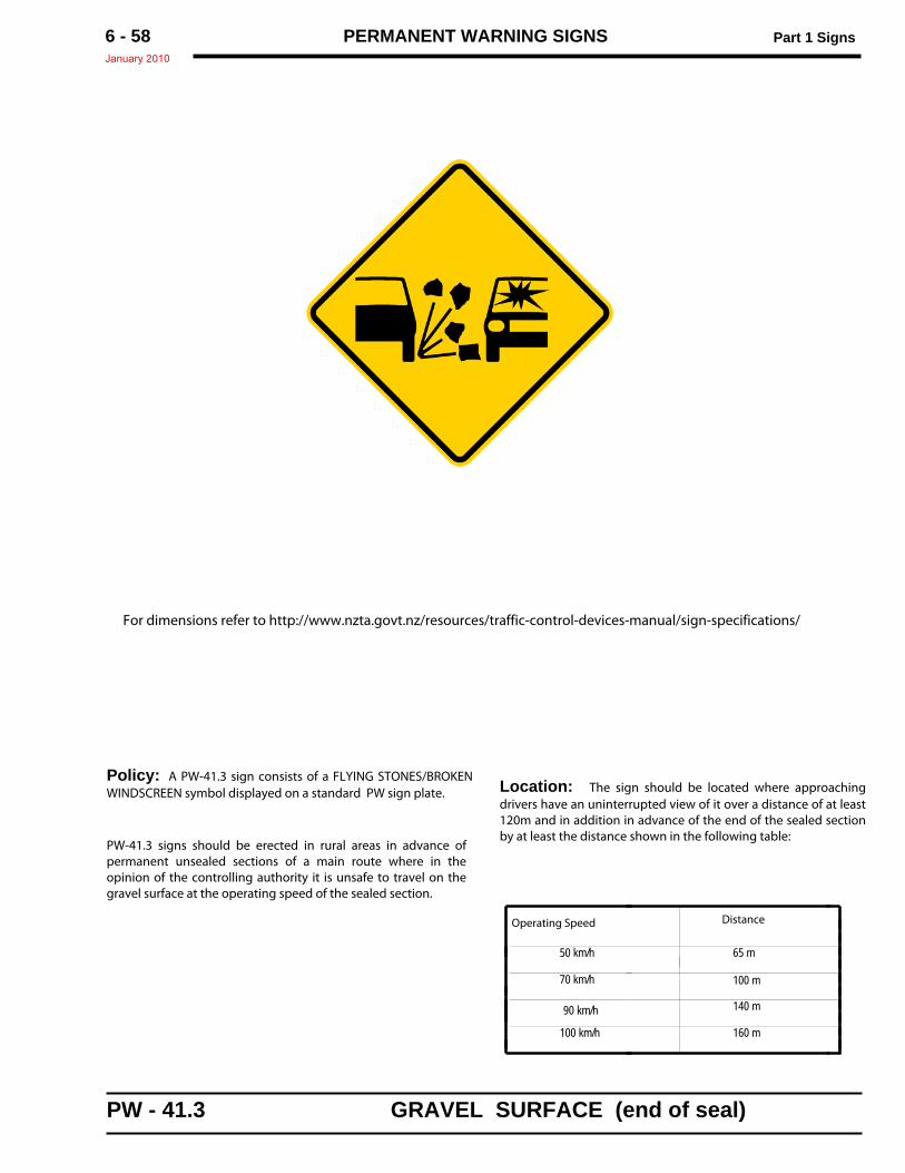
PERMANENT WARNING SIGNS Part 1 SignsJanuary 2010
6 - 58
Policy: A PW-41.3 sign consists of a FLYING STONES/BROKENWINDSCREEN symbol displayed on a standard PW sign plate.
PW-41.3 signs should be erected in rural areas in advance ofpermanent unsealed sections of a main route where in theopinion of the controlling authority it is unsafe to travel on thegravel surface at the operating speed of the sealed section.
Location: The sign should be located where approachingdrivers have an uninterrupted view of it over a distance of at least120m and in addition in advance of the end of the sealed sectionby at least the distance shown in the following table:
For dimensions refer to http://www.nzta.govt.nz/resources/traffic-control-devices-manual/sign-specifications/
PW - 41.3 GRAVEL SURFACE (end of seal)
Operating Speed Distance
50 km/h 65 m
70 km/h 100 m
90 km/h 140 m
160 m100 km/h
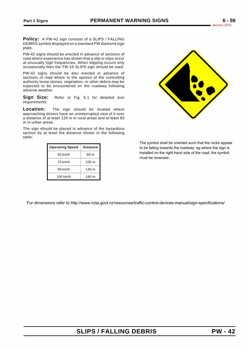
Part 1 Signs PERMANENT WARNING SIGNSJanuary 2010
6 - 59
SLIPS / FALLING DEBRIS PW - 42
.
.
Sign Size a750 x 750 50
900 x 900 60
Policy: A PW-42 sign consists of a SLIPS / FALLINGDEBRIS symbol displayed on a standard PW diamond signplate.
PW-42 signs should be erected in advance of sections ofroad where experience has shown that a slip or slips occurat unusually high frequencies. When slipping occurs onlyoccasionally then the TW-16 SLIPS sign should be used.
PW-42 signs should be also erected in advance ofsections of road where in the opinion of the controllingauthority loose stones, vegetation, or other debris may beexpected to be encountered on the roadway followingadverse weather.
Sign Size: Refer to Fig. 6.1 for detailed sizerequirements.
Location: The sign should be located whereapproaching drivers have an uninterrupted view of it overa distance of at least 120 m in rural areas and at least 60m in urban areas.
The sign should be placed in advance of the hazardoussection by at least the distance shown in the followingtable:
Operating Speed Distance
50 km/h 65 m
70 km/h 100 m
90 km/h 140 m
100 km/h 160 m
For dimensions refer to http://www.nzta.govt.nz/resources/traffic-control-devices-manual/sign-specifications/
The symbol shall be oriented such that the rocks appear to be falling towards the roadway; eg where the sign is installed on the right hand side of the road, the symbol must be reversed.
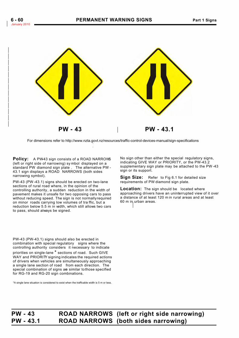
PERMANENT WARNING SIGNS Part 1 SignsJanuary 2010*6 - 60
PW - 43 ROAD NARROWS (left or right side narrowing)PW - 43.1 ROAD NARROWS (both sides narrowing)
PW - 43 PW - 43.1*
*
*
*
*
*
*
*
*
*
*
*
*
*
.
.
Policy: A PW-43 sign consists of a ROAD NARROWS(left or right side of narrowing) sy mbol displayed on astandard PW diamond sign plate . The alternative PW -43.1 sign displays a ROAD NARROWS (both sidesnarrowing symbol).
PW-43 (PW -43.1) signs should be erected on two-lanesections of rural road where, in the opinion of thecontrolling authority , a sudden reduction in the width ofpavement makes it unsafe for two opposing cars to passwithout reducing speed. The sign is not normally requiredon minor roads carrying low volumes of tra ffic, but areduction below 5.5 m in width, which still allows two carsto pass, should always be signed.
.
.
.
.
.
PW-43 (PW-43.1) signs should also be erected incombination with special regulatory signs where thecontrolling authority considers it necessary to indicatepriorities on single-lane * sections of road. Such GIVEWAY and PRIORITY signing indicates the required actionsof drivers when vehicles are simultaneously approachinga single lane section of road from each direction. Thespecial combination of signs are similar to those specifiedfor RG-19 and RG-20 sign combinations.
No sign other than either the special regulatory signs,indicating GIVE WAY or PRIORITY, or the PW-43.2supplementary sign plate may be attached to the PW -43sign or its support.
Sign Size: Refer to Fig 6.1 for detailed sizerequirements of PW diamond sign plate.
Location: The sign should be located whereapproaching drivers have an uninterrupted view of it overa distance of at least 120 m in rural areas and at least 60 m in urban areas.
*
*A single lane situation is considered to exist when the trafficable width is 5 m or less.
For dimensions refer to http://www.nzta.govt.nz/resources/traffic-control-devices-manual/sign-specifications
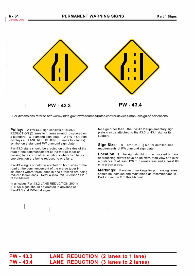
PERMANENT WARNING SIGNS Part 1 SignsJanuary 2010*6 - 61
PW - 43.3 LANE REDUCTION (2 lanes to 1 lane)PW - 43.4 LANE REDUCTION (3 lanes to 2 lanes)
PW - 43.3*
*
*
*
*
*
*
*
*
*
*
*
*
*
.
.
Policy: A PW-43.3 sign consists of a LANE REDUCTION (2 lanes to 1 lane) sy mbol displayed ona standard PW diamond sign plate . A PW -43.4 signdisplays a LANE REDUCTION ( 3 lanes to 2 lanes)symbol on a standard PW diamond sign plate.
PW-43.3 signs should be erected on both sides of the road at the commencement of the merge taper on passing lanes or in other situations where two lanes in one direction are being reduced to one lane. . PW-43.4 signs should be erected on both sides of the road at the commencement of the merge taper in situations where three lanes in one direction are being
.
.In all cases PW-43.2 LANE REDUCTION 200 m AHEAD signs should be erected in advance of PW-43.3 and PW-43.4 signs.
.
.
.*.... ..
No sign other than the PW-43.2 supplementary signplate may be attached to the 43.3 or 43.4 sign or its.support..
Sign Size: R efer to F ig 6.1 for detailed sizerequirements of PW diamond sign plate.
Location: T he sign should b e located w hereapproaching drivers have an uninterrupted view of it overa distance of at least 120 m in rural areas and at least 60m in urban areas.
Markings: Pavement markings for p assing lanesshould be installed and maintained as recommended inPart 2, Section 2 of this Manual. ..
.
.
.
.*.*
PW - 43.4
For dimensions refer to http://www.nzta.govt.nz/resources/traffic-control-devices-manual/sign-specifications
reduced to two lanes. Refer also to Part 3 Section 11.2of this Manual.
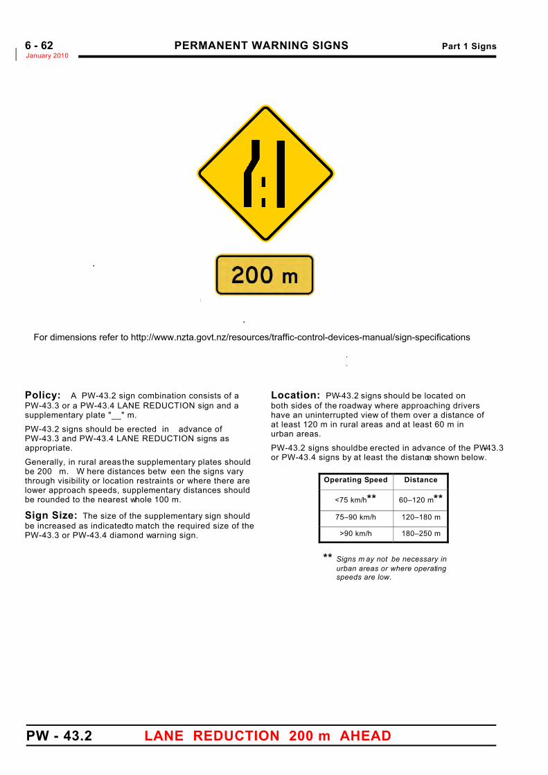
PERMANENT WARNING SIGNS Part 1 SignsJanuary 2010*6 - 62
PW - 43.2 LANE REDUCTION 200 m AHEAD
.
.
.
PW-43Sign Size
Matching Supplemen*
.
600 x 600 600 250 96 * 50*
750 x 750 750 300 107* 65*
900 x 900 900 350 144* 75*
Policy: A PW-43.2 sign combination consists of aPW-43.3 or a PW-43.4 LANE REDUCTION sign and a supplementary plate "__" m.
PW-43.2 signs should be erected in advance of PW-43.3 and PW-43.4 LANE REDUCTION signs asappropriate.
Generally, in rural areas the supplementary plates shouldbe 200 m. W here distances betw een the signs varythrough visibility or location restraints or where there arelower approach speeds, supplementary distances shouldbe rounded to the nearest whole 100 m.
Sign Size: The size of the supplementary sign shouldbe increased as indicated to match the required size of thePW-43.3 or PW-43.4 diamond warning sign.
Location: PW-43.2 signs should be located on both sides of the roadway where approaching drivershave an uninterrupted view of them over a distance ofat least 120 m in rural areas and at least 60 m inurban areas.
PW-43.2 signs should be erected in advance of the PW-43.3or PW-43.4 signs by at least the distance shown below.
Operating Speed Distance
<75 km/h** 60–120 m**75–90 km/h 120–180 m
>90 km/h 180–250 m
** Signs m ay not be necessary inurban areas or where operatingspeeds are low.
For dimensions refer to http://www.nzta.govt.nz/resources/traffic-control-devices-manual/sign-specifications
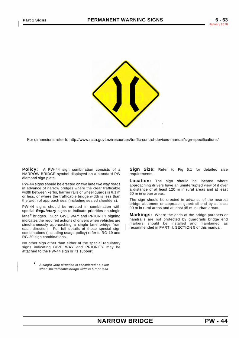
Part 1 Signs PERMANENT WARNING SIGNSJanuary 2010*
6 - 63
NARROW BRIDGE PW - 44
.
.
Sign Size a b c600 x 600 100 60 120
750 x 750 125 75 150
900 x 900 150 90 180
Policy: A PW-44 sign combination consists of aNARROW BRIDGE symbol displayed on a standard PWdiamond sign plate.
PW-44 signs should be erected on two lane two way roadsin advance of narrow bridges where the clear trafficablewidth between kerbs, barrier rails or wheel guards is 6.1 mor less, or where the trafficable bridge width is less thanthe width of approach seal (including sealed shoulders).
PW-44 signs should be erected in combination withspecial Regulatory signs to indicate priorities on singlelane* bridges. Such GIVE WAY and PRIORITY signingindicates the required actions of drivers when vehicles aresimultaneously approaching a single lane bridge fromeach direction. For full details of these special signcombinations (including usage policy) refer to RG-19 andRG-20 sign combinations.
No other sign other than either of the special regulatorysigns indicating GIVE WAY and PRIORITY may beattached to the PW-44 sign or its support.
* A singl e lane sit uation is considered t o exist*when the trafficable bridge width is 5 m or less.*
Sign Size: Refer to Fig 6.1 for detailed sizerequirements.
Location: The sign should be located whereapproaching drivers have an uninterrupted view of it overa distance of at least 120 m in rural areas and at least60 m in urban areas.
The sign should be erected in advance of the nearestbridge abutment or approach guardrail end by at least90 m in rural areas and at least 45 m in urban areas.
Markings: Where the ends of the bridge parapets orhandrails are not protected by guardrails bridge endmarkers should be installed and maintained asrecommended in PART II, SECTION 5 of this manual.*
For dimensions refer to http://www.nzta.govt.nz/resources/traffic-control-devices-manual/sign-specifications/
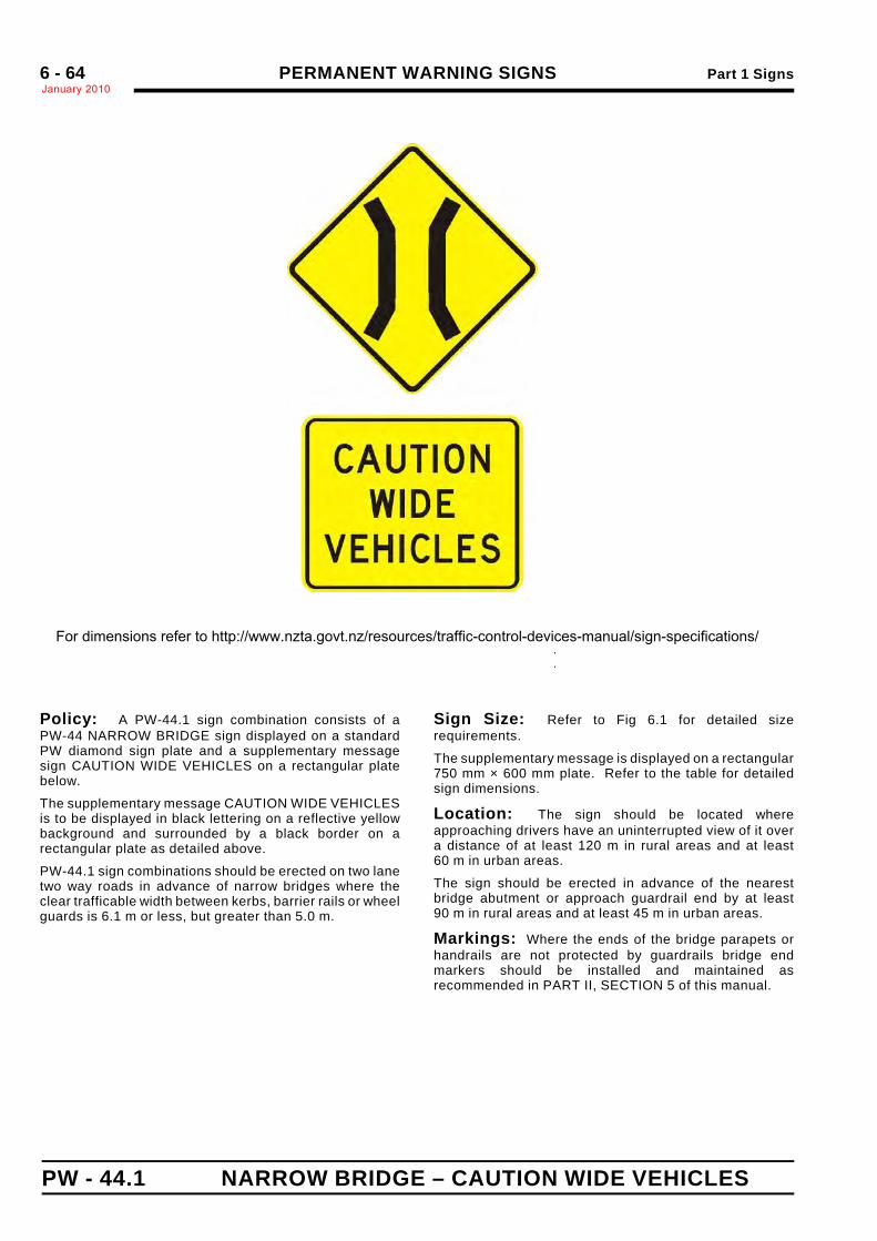
PERMANENT WARNING SIGNS Part 1 SignsJanuary 20106 - 64
PW - 44.1 NARROW BRIDGE – CAUTION WIDE VEHICLES
.
.
a b c d e f750 600 150 544 296 610
Policy: A PW-44.1 sign combination consists of aPW-44 NARROW BRIDGE sign displayed on a standardPW diamond sign plate and a supplementary messagesign CAUTION WIDE VEHICLES on a rectangular platebelow.
The supplementary message CAUTION WIDE VEHICLESis to be displayed in black lettering on a reflective yellowbackground and surrounded by a black border on arectangular plate as detailed above.
PW-44.1 sign combinations should be erected on two lanetwo way roads in advance of narrow bridges where theclear trafficable width between kerbs, barrier rails or wheelguards is 6.1 m or less, but greater than 5.0 m.
Sign Size: Refer to Fig 6.1 for detailed sizerequirements.
The supplementary message is displayed on a rectangular750 mm × 600 mm plate. Refer to the table for detailedsign dimensions.
Location: The sign should be located whereapproaching drivers have an uninterrupted view of it overa distance of at least 120 m in rural areas and at least60 m in urban areas.
The sign should be erected in advance of the nearestbridge abutment or approach guardrail end by at least90 m in rural areas and at least 45 m in urban areas.
Markings: Where the ends of the bridge parapets orhandrails are not protected by guardrails bridge endmarkers should be installed and maintained asrecommended in PART II, SECTION 5 of this manual.
For dimensions refer to http://www.nzta.govt.nz/resources/traffic-control-devices-manual/sign-specifications/
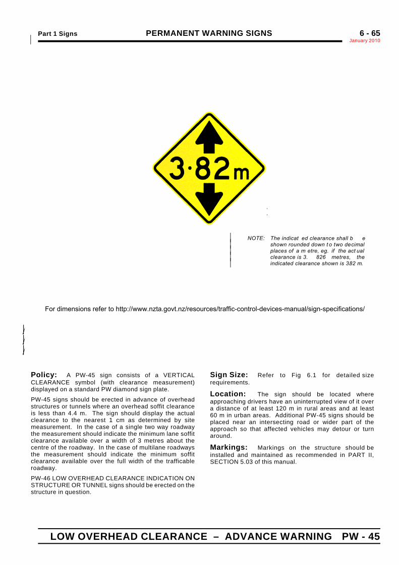
Part 1 Signs PERMANENT WARNING SIGNSJanuary 2010*
6 - 65
LOW OVERHEAD CLEARANCE – ADVANCE WARNING PW - 45
.
.
.
NOTE: The indicat ed clearance shall b e*shown rounded down t o two decimal*places of a m etre, eg. if the act ual*clearance is 3. 826 metres, the*indicated clearance shown is 3.82 m.*
Sign Size a b c d e Symbol "m"(loop height)
DistanceNumerals
600 x 600 80 110 120 40* 107* 75 Mod.E* 150 D
750 x 750 100 135 150 50* 128* 90 Mod.E* 180 D
900 x 900 120 165 180 60* 163* 115 Mod.E* 225 D
Policy: A PW-45 sign consists of a VERTICALCLEARANCE symbol (with clearance measurement)displayed on a standard PW diamond sign plate.
PW-45 signs should be erected in advance of overheadstructures or tunnels where an overhead soffit clearanceis less than 4.4 m. The sign should display the actualclearance to the nearest 1 cm as determined by sitemeasurement. In the case of a single two way roadwaythe measurement should indicate the minimum lane soffitclearance available over a width of 3 metres about thecentre of the roadway. In the case of multilane roadwaysthe measurement should indicate the minimum soffitclearance available over the full width of the trafficableroadway.
PW-46 LOW OVERHEAD CLEARANCE INDICATION ONSTRUCTURE OR TUNNEL signs should be erected on thestructure in question.
Sign Size: Refer to Fig 6.1 for detailed sizerequirements.
Location: The sign should be located whereapproaching drivers have an uninterrupted view of it overa distance of at least 120 m in rural areas and at least60 m in urban areas. Additional PW-45 signs should beplaced near an intersecting road or wider part of theapproach so that affected vehicles may detour or turnaround.
Markings: Markings on the structure should beinstalled and maintained as recommended in PART II,SECTION 5.03 of this manual.
For dimensions refer to http://www.nzta.govt.nz/resources/traffic-control-devices-manual/sign-specifications/
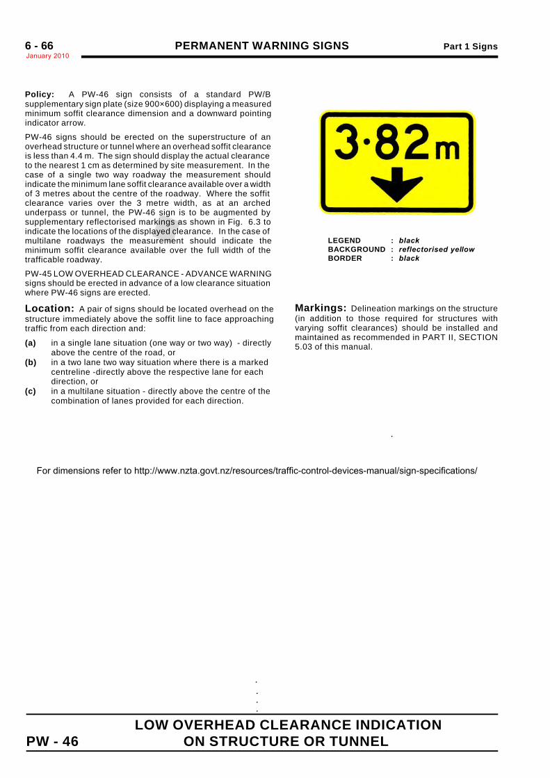
PERMANENT WARNING SIGNS Part 1 SignsJanuary 20106 - 66
LOW OVERHEAD CLEARANCE INDICATIONPW - 46 ON STRUCTURE OR TUNNEL
. . . .
LEGEND : blackBACKGROUND : reflectorised yellowBORDER : black
.
Policy: A PW-46 sign consists of a standard PW/Bsupplementary sign plate (size 900×600) displaying a measuredminimum soffit clearance dimension and a downward pointingindicator arrow.
PW-46 signs should be erected on the superstructure of anoverhead structure or tunnel where an overhead soffit clearanceis less than 4.4 m. The sign should display the actual clearanceto the nearest 1 cm as determined by site measurement. In thecase of a single two way roadway the measurement shouldindicate the minimum lane soffit clearance available over a widthof 3 metres about the centre of the roadway. Where the soffitclearance varies over the 3 metre width, as at an archedunderpass or tunnel, the PW-46 sign is to be augmented bysupplementary reflectorised markings as shown in Fig. 6.3 toindicate the locations of the displayed clearance. In the case ofmultilane roadways the measurement should indicate theminimum soffit clearance available over the full width of thetrafficable roadway.
PW-45 LOW OVERHEAD CLEARANCE - ADVANCE WARNINGsigns should be erected in advance of a low clearance situationwhere PW-46 signs are erected.
Location: A pair of signs should be located overhead on thestructure immediately above the soffit line to face approachingtraffic from each direction and:
(a) in a single lane situation (one way or two way) - directlyabove the centre of the road, or
(b) in a two lane two way situation where there is a markedcentreline -directly above the respective lane for eachdirection, or
(c) in a multilane situation - directly above the centre of thecombination of lanes provided for each direction.
Markings: Delineation markings on the structure(in addition to those required for structures withvarying soffit clearances) should be installed andmaintained as recommended in PART II, SECTION5.03 of this manual.
For dimensions refer to http://www.nzta.govt.nz/resources/traffic-control-devices-manual/sign-specifications/
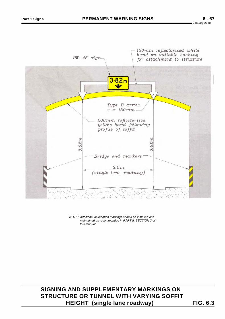
Part 1 Signs PERMANENT WARNING SIGNSJanuary 2010
6 - 67
SIGNING AND SUPPLEMENTARY MARKINGS ON STRUCTURE OR TUNNEL WITH VARYING SOFFIT
HEIGHT (single lane roadway) FIG. 6.3
NOTE: Additional delineation markings should be installed andmaintained as recommended in PART II, SECTION 3 ofthis manual.
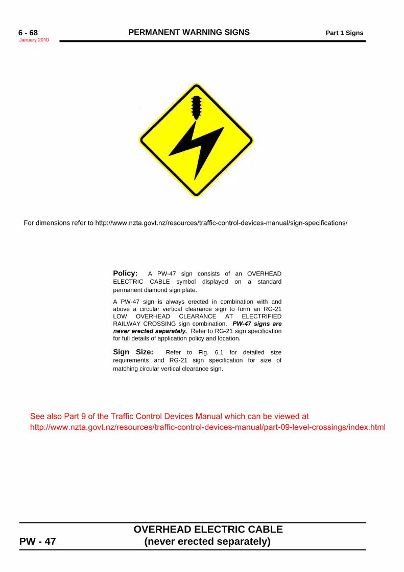
PERMANENT WARNING SIGNS Part 1 SignsJanuary 20106 - 68
OVERHEAD ELECTRIC CABLEPW - 47 (never erected separately)
Sign Size a600 x 600 40
750 x 750 50
900 x 900 60
Policy: A PW-47 sign consists of an OVERHEADELECTRIC CABLE symbol displayed on a standardpermanent diamond sign plate.
A PW-47 sign is always erected in combination with andabove a circular vertical clearance sign to form an RG-21LOW OVERHEAD CLEARANCE AT ELECTRIFIEDRAILWAY CROSSING sign combination. PW-47 signs arenever erected separately. Refer to RG-21 sign specificationfor full details of application policy and location.
Sign Size: Refer to Fig. 6.1 for detailed sizerequirements and RG-21 sign specification for size ofmatching circular vertical clearance sign.
For dimensions refer to http://www.nzta.govt.nz/resources/traffic-control-devices-manual/sign-specifications/
See also Part 9 of the Traffic Control Devices Manual which can be viewed at http://www.nzta.govt.nz/resources/traffic-control-devices-manual/part-09-level-crossings/index.html
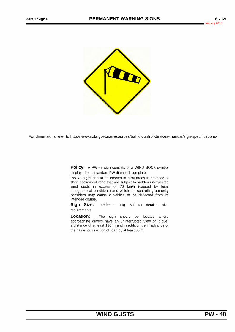
Part 1 Signs PERMANENT WARNING SIGNSJanuary 2010
6 - 69
WIND GUSTS PW - 48
Sign Size a600 x 600 40
750 x 750 50
900 x 900 60
Policy: A PW-48 sign consists of a WIND SOCK symboldisplayed on a standard PW diamond sign plate.PW-48 signs should be erected in rural areas in advance ofshort sections of road that are subject to sudden unexpectedwind gusts in excess of 70 km/h (caused by localtopographical conditions) and which the controlling authorityconsiders may cause a vehicle to be deflected from itsintended course.Sign Size: Refer to Fig. 6.1 for detailed sizerequirements.
Location: The sign should be located whereapproaching drivers have an uninterrupted view of it overa distance of at least 120 m and in addition be in advance ofthe hazardous section of road by at least 60 m.
For dimensions refer to http://www.nzta.govt.nz/resources/traffic-control-devices-manual/sign-specifications/
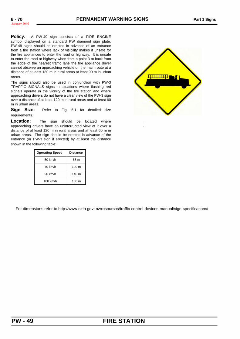
PERMANENT WARNING SIGNS Part 1 SignsJanuary 20106 - 70
PW - 49 FIRE STATION
.
.
Sign Size ab
600 x 600 40 5
750 x 750 50 6
900 x 900 60 8
Policy: A PW-49 sign consists of a FIRE ENGINEsymbol displayed on a standard PW diamond sign plate.PW-49 signs should be erected in advance of an entrancefrom a fire station where lack of visibility makes it unsafe forthe fire appliances to enter the road or highway. It is unsafeto enter the road or highway when from a point 3 m back fromthe edge of the nearest traffic lane the fire appliance drivercannot observe an approaching vehicle on the main route at adistance of at least 180 m in rural areas at least 90 m in urbanareas.The signs should also be used in conjunction with PW-3TRAFFIC SIGNALS signs in situations where flashing redsignals operate in the vicinity of the fire station and whereapproaching drivers do not have a clear view of the PW-3 signover a distance of at least 120 m in rural areas and at least 60m in urban areas.Sign Size: Refer to Fig. 6.1 for detailed sizerequirements.
Location: The sign should be located whereapproaching drivers have an uninterrupted view of it over adistance of at least 120 m in rural areas and at least 60 m inurban areas. The sign should be erected in advance of theentrance (or PW-3 sign if erected) by at least the distanceshown in the following table:
Operating Speed Distance
50 km/h 65 m
70 km/h 100 m
90 km/h 140 m
100 km/h 160 m
For dimensions refer to http://www.nzta.govt.nz/resources/traffic-control-devices-manual/sign-specifications/
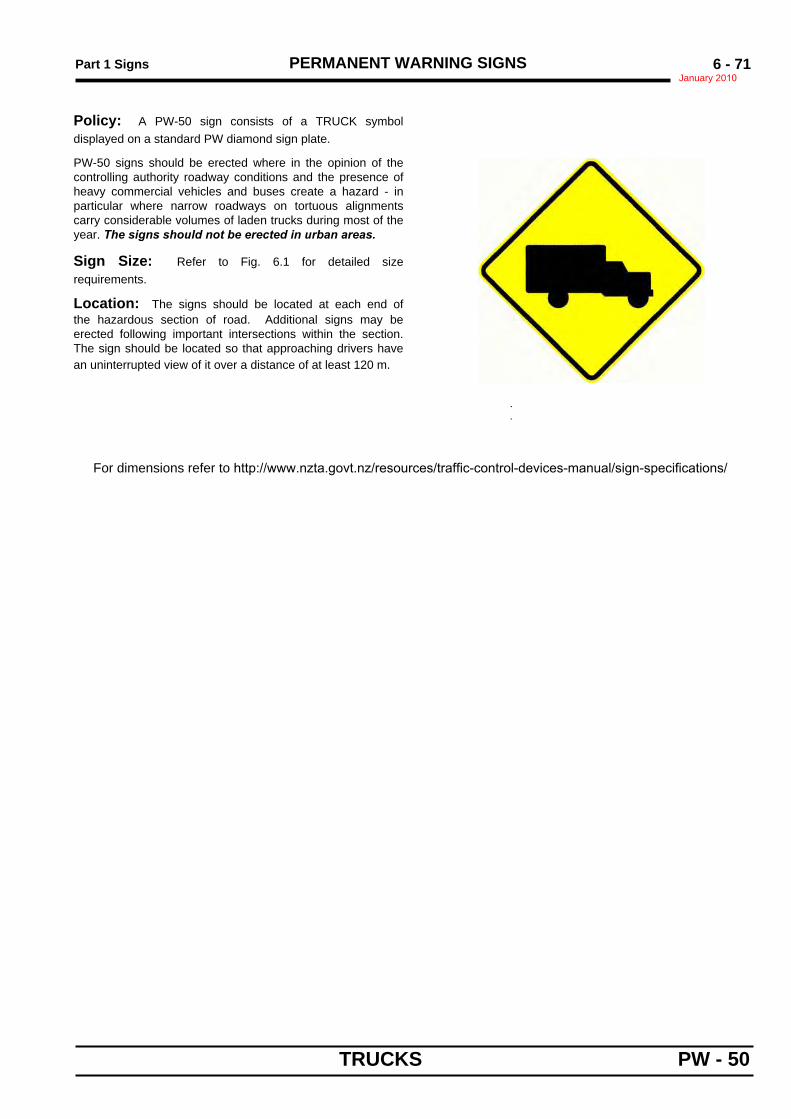
Part 1 Signs PERMANENT WARNING SIGNSJanuary 2010
6 - 71
TRUCKS PW - 50
.
.
Sign Size a600 x 600 40
750 x 750 50
900 x 900 60
Policy: A PW-50 sign consists of a TRUCK symboldisplayed on a standard PW diamond sign plate.
PW-50 signs should be erected where in the opinion of thecontrolling authority roadway conditions and the presence ofheavy commercial vehicles and buses create a hazard - inparticular where narrow roadways on tortuous alignmentscarry considerable volumes of laden trucks during most of theyear. The signs should not be erected in urban areas.
Sign Size: Refer to Fig. 6.1 for detailed sizerequirements.
Location: The signs should be located at each end ofthe hazardous section of road. Additional signs may beerected following important intersections within the section.The sign should be located so that approaching drivers havean uninterrupted view of it over a distance of at least 120 m.
For dimensions refer to http://www.nzta.govt.nz/resources/traffic-control-devices-manual/sign-specifications/
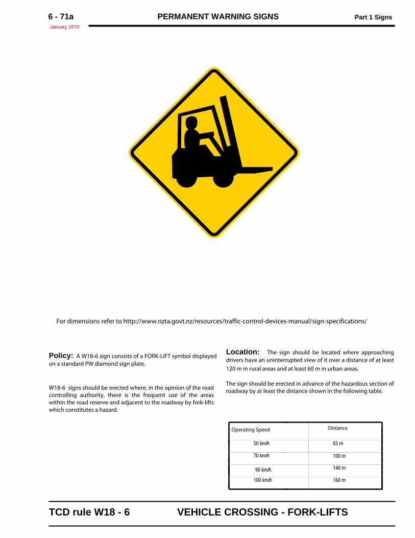
PERMANENT WARNING SIGNS Part 1 Signs January 2010
6 - 71a
Policy: A W18-6 sign consists of a FORK-LIFT symbol displayedon a standard PW diamond sign plate.
W18-6 signs should be erected where, in the opinion of the roadcontrolling authority, there is the frequent use of the areaswithin the road reserve and adjacent to the roadway by fork-liftswhich constitutes a hazard.
For dimensions refer to http://www.nzta.govt.nz/resources/traffic-control-devices-manual/sign-specifications/
TCD rule W18 - 6 VEHICLE CROSSING - FORK-LIFTS
Location: The sign should be located where approachingdrivers have an uninterrupted view of it over a distance of at least120 m in rural areas and at least 60 m in urban areas.
The sign should be erected in advance of the hazardous section ofroadway by at least the distance shown in the following table.
Operating Speed Distance
50 km/h 65 m
70 km/h 100 m
90 km/h 140 m
160 m100 km/h
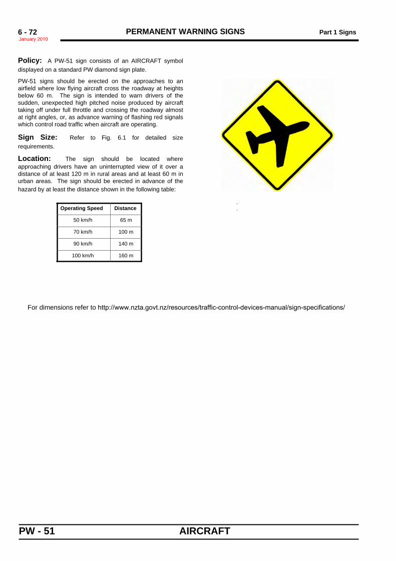
PERMANENT WARNING SIGNS Part 1 SignsJanuary 20106 - 72
PW - 51 AIRCRAFT
.
.
Sign Size a600 x 600 40
750 x 750 50
900 x 900 60
Policy: A PW-51 sign consists of an AIRCRAFT symboldisplayed on a standard PW diamond sign plate.
PW-51 signs should be erected on the approaches to anairfield where low flying aircraft cross the roadway at heightsbelow 60 m. The sign is intended to warn drivers of thesudden, unexpected high pitched noise produced by aircrafttaking off under full throttle and crossing the roadway almostat right angles, or, as advance warning of flashing red signalswhich control road traffic when aircraft are operating.
Sign Size: Refer to Fig. 6.1 for detailed sizerequirements.
Location: The sign should be located whereapproaching drivers have an uninterrupted view of it over adistance of at least 120 m in rural areas and at least 60 m inurban areas. The sign should be erected in advance of thehazard by at least the distance shown in the following table:
Operating Speed Distance
50 km/h 65 m
70 km/h 100 m
90 km/h 140 m
100 km/h 160 m
For dimensions refer to http://www.nzta.govt.nz/resources/traffic-control-devices-manual/sign-specifications/
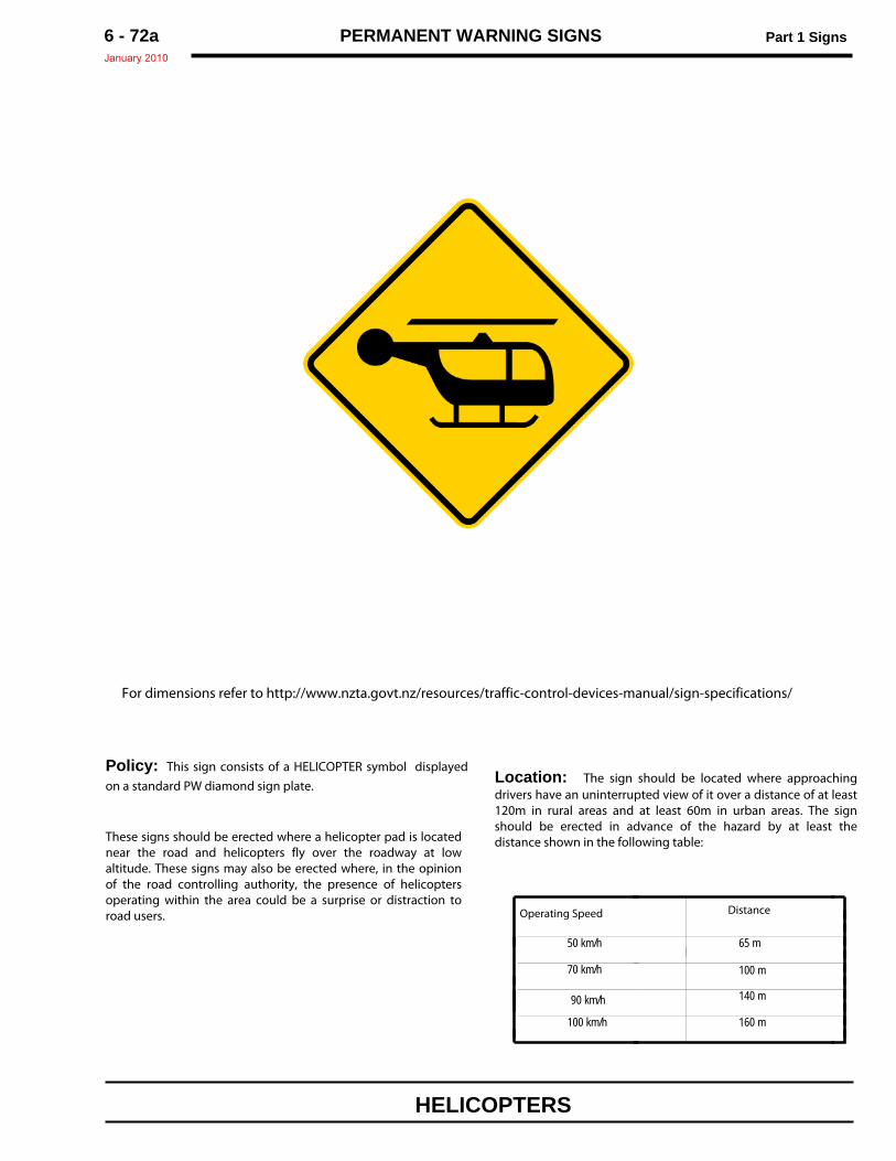
PERMANENT WARNING SIGNS Part 1 SignsJanuary 2010
6 - 72a
Policy: This sign consists of a HELICOPTER symbol displayedon a standard PW diamond sign plate.
These signs should be erected where a helicopter pad is locatednear the road and helicopters fly over the roadway at lowaltitude. These signs may also be erected where, in the opinionof the road controlling authority, the presence of helicoptersoperating within the area could be a surprise or distraction toroad users.
Location: The sign should be located where approachingdrivers have an uninterrupted view of it over a distance of at least120m in rural areas and at least 60m in urban areas. The signshould be erected in advance of the hazard by at least thedistance shown in the following table:
For dimensions refer to http://www.nzta.govt.nz/resources/traffic-control-devices-manual/sign-specifications/
HELICOPTERS
Operating Speed Distance
50 km/h 65 m
70 km/h 100 m
90 km/h 140 m
160 m100 km/h
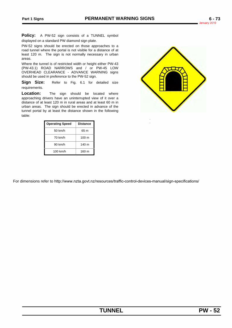
Part 1 Signs PERMANENT WARNING SIGNSJanuary 2010
6 - 73
TUNNEL PW - 52
.
.
Sign Size ab
600 x 600 40 7
750 x 750 50 9
900 x 900 60 11
Policy: A PW-52 sign consists of a TUNNEL symboldisplayed on a standard PW diamond sign plate.PW-52 signs should be erected on those approaches to aroad tunnel where the portal is not visible for a distance of atleast 120 m. The sign is not normally necessary in urbanareas.Where the tunnel is of restricted width or height either PW-43(PW-43.1) ROAD NARROWS and / or PW-45 LOWOVERHEAD CLEARANCE - ADVANCE WARNING signsshould be used in preference to the PW-52 sign.
Sign Size: Refer to Fig. 6.1 for detailed sizerequirements.
Location: The sign should be located whereapproaching drivers have an uninterrupted view of it over adistance of at least 120 m in rural areas and at least 60 m inurban areas. The sign should be erected in advance of thetunnel portal by at least the distance shown in the followingtable:
Operating Speed Distance
50 km/h 65 m
70 km/h 100 m
90 km/h 140 m
100 km/h 160 m
For dimensions refer to http://www.nzta.govt.nz/resources/traffic-control-devices-manual/sign-specifications/
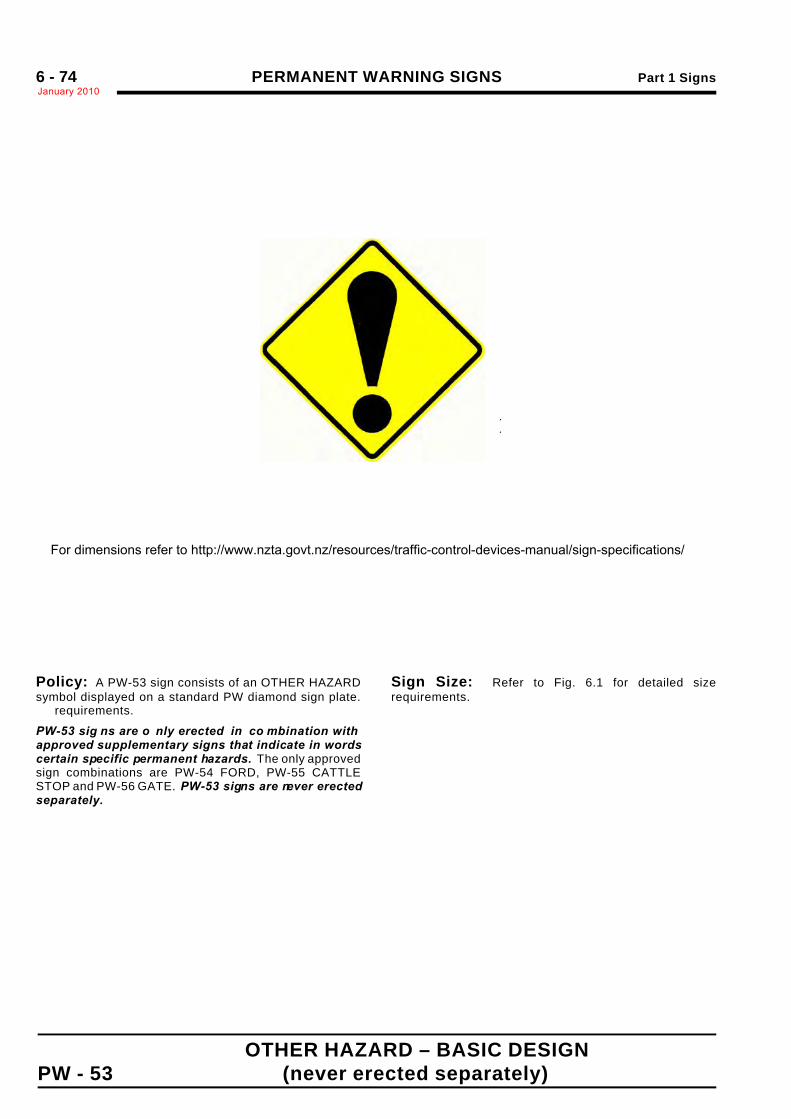
PERMANENT WARNING SIGNS Part 1 SignsJanuary 20106 - 74
OTHER HAZARD – BASIC DESIGNPW - 53 (never erected separately)
.
.
Sign Size a b c d e600 x 600 180 290 420 30 140
750 x 750 225 360 525 40 175
900 x 900 270 430 630 50 210
Policy: A PW-53 sign consists of an OTHER HAZARDsymbol displayed on a standard PW diamond sign plate.
requirements.
PW-53 sig ns are o nly erected in co mbination withapproved supplementary signs that indicate in wordscertain specific permanent hazards. The only approvedsign combinations are PW-54 FORD, PW-55 CATTLESTOP and PW-56 GATE. PW-53 signs are never erectedseparately.
Sign Size: Refer to Fig. 6.1 for detailed sizerequirements.
For dimensions refer to http://www.nzta.govt.nz/resources/traffic-control-devices-manual/sign-specifications/
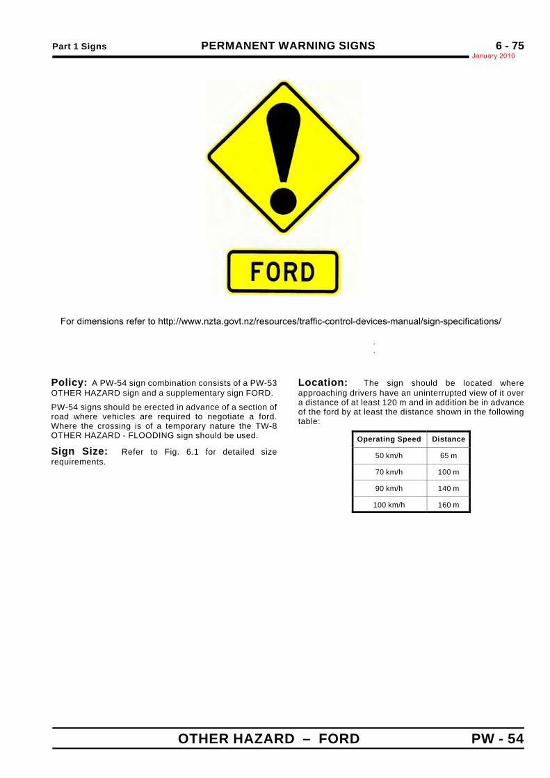
Part 1 Signs PERMANENT WARNING SIGNSJanuary 2010
6 - 75
OTHER HAZARD – FORD PW - 54
.
.
.
PW-53 Sign Size a600 x 600 600 250 329 100 D
750 x 750 750 300 413 125 D
900 x 900 900 350 493 150 D
Policy: A PW-54 sign combination consists of a PW-53OTHER HAZARD sign and a supplementary sign FORD.
PW-54 signs should be erected in advance of a section ofroad where vehicles are required to negotiate a ford.Where the crossing is of a temporary nature the TW-8OTHER HAZARD - FLOODING sign should be used.
Sign Size: Refer to Fig. 6.1 for detailed sizerequirements.
Location: The sign should be located whereapproaching drivers have an uninterrupted view of it overa distance of at least 120 m and in addition be in advanceof the ford by at least the distance shown in the followingtable:
Operating Speed Distance
50 km/h 65 m
70 km/h 100 m
90 km/h 140 m
100 km/h 160 m
For dimensions refer to http://www.nzta.govt.nz/resources/traffic-control-devices-manual/sign-specifications/
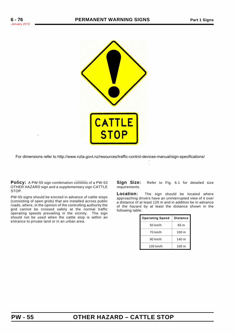
PERMANENT WARNING SIGNS Part 1 SignsJanuary 20106 - 76
PW - 55 OTHER HAZARD – CATTLE STOP
.
.
.
PW-53 Sign Size a b c600 x 600 600 400 150 461 324 100 D
750 x 750 750 500 190 577 407 125 D
900 x 900 900 600 225 689 485 150 D
Policy: A PW-55 sign combination consists of a PW-53OTHER HAZARD sign and a supplementary sign CATTLESTOP.
PW-55 signs should be erected in advance of cattle stops(consisting of open grids) that are installed across publicroads, where, in the opinion of the controlling authority thegrid cannot be crossed safely at the normal trafficoperating speeds prevailing in the vicinity. The signshould not be used when the cattle stop is within anentrance to private land or in an urban area.
Sign Size: Refer to Fig. 6.1 for detailed sizerequirements.
Location: The sign should be located whereapproaching drivers have an uninterrupted view of it overa distance of at least 120 m and in addition be in advanceof the hazard by at least the distance shown in thefollowing table:
Operating Speed Distance
50 km/h 65 m
70 km/h 100 m
90 km/h 140 m
100 km/h 160 m
For dimensions refer to http://www.nzta.govt.nz/resources/traffic-control-devices-manual/sign-specifications/
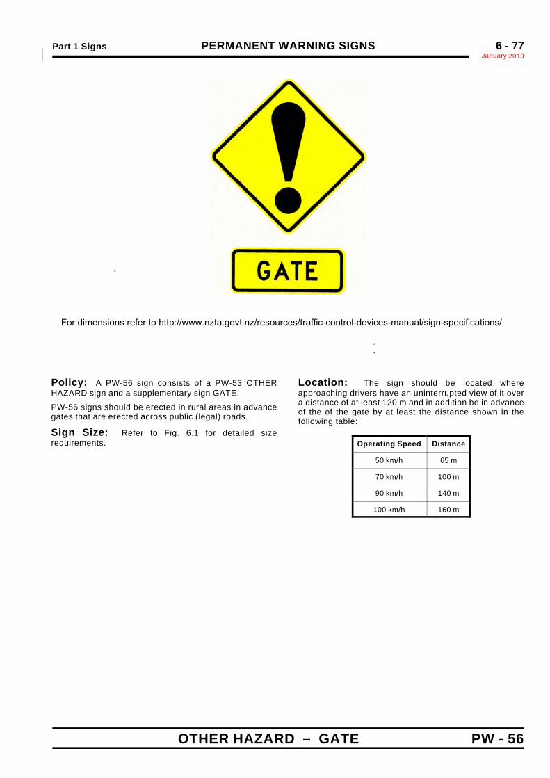
Part 1 Signs PERMANENT WARNING SIGNSJanuary 2010*
6 - 77
OTHER HAZARD – GATE PW - 56
.
.
.*
PW-53 Sign Size a b600 x 600 600 250 329 100 D
750 x 750 750 300 413 125 D
900 x 900 900 350 493 150 D
Policy: A PW-56 sign consists of a PW-53 OTHERHAZARD sign and a supplementary sign GATE.
PW-56 signs should be erected in rural areas in advancegates that are erected across public (legal) roads.
Sign Size: Refer to Fig. 6.1 for detailed sizerequirements.
Location: The sign should be located whereapproaching drivers have an uninterrupted view of it overa distance of at least 120 m and in addition be in advanceof the of the gate by at least the distance shown in thefollowing table:
Operating Speed Distance
50 km/h 65 m
70 km/h 100 m
90 km/h 140 m
100 km/h 160 m
For dimensions refer to http://www.nzta.govt.nz/resources/traffic-control-devices-manual/sign-specifications/
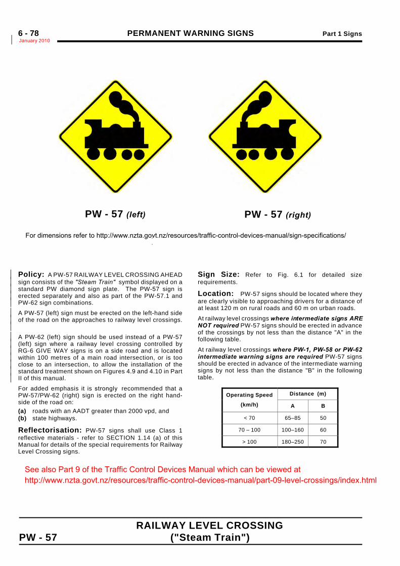
PERMANENT WARNING SIGNS Part 1 SignsJanuary 2010*6 - 78
RAILWAY LEVEL CROSSING PW - 57 ("Steam Train")
PW - 57 (left)
.
.
Policy: A PW-57 RAILWAY LEVEL CROSSING AHEAD*sign consists of the "Steam Train" symbol displayed on a*standard PW diamond sign plate. The PW-57 sign is*erected separately and also as part of the PW-57.1 and*PW-62 sign combinations.*
A PW-57 (left) sign must be erected on the left-hand side*of the road on the approaches to railway level crossings.*
*
A PW-62 (left) sign should be used instead of a PW-57*(left) sign where a railway level crossing controlled by*RG-6 GIVE WAY signs is on a side road and is located*within 100 metres of a main road intersection, or is too*close to an intersection, to allow the installation of the*standard treatment shown on Figures 4.9 and 4.10 in Part*II of this manual.*
For added emphasis it is strongly recommended that aPW-57/PW-62 (right) sign is erected on the right hand-side of the road on:(a) roads with an AADT greater than 2000 vpd, and(b) state highways.
Reflectorisation: PW-57 signs shall use Class 1reflective materials - refer to SECTION 1.14 (a) of thisManual for details of the special requirements for RailwayLevel Crossing signs.
Sign Size: Refer to Fig. 6.1 for detailed sizerequirements.
Location: PW-57 signs should be located where theyare clearly visible to approaching drivers for a distance ofat least 120 m on rural roads and 60 m on urban roads.
At railway level crossings where intermediate signs ARENOT required PW-57 signs should be erected in advanceof the crossings by not less than the distance "A" in thefollowing table.
At railway level crossings where PW-1, PW-58 or PW-62intermediate warning signs are required PW-57 signsshould be erected in advance of the intermediate warningsigns by not less than the distance "B" in the followingtable.
Operating Speed
(km/h)
Distance (m)
A B
< 70 65–85 50
70 – 100 100–160 60
> 100 180–250 70
PW - 57 (right)
For dimensions refer to http://www.nzta.govt.nz/resources/traffic-control-devices-manual/sign-specifications/
See also Part 9 of the Traffic Control Devices Manual which can be viewed at http://www.nzta.govt.nz/resources/traffic-control-devices-manual/part-09-level-crossings/index.html
Part 1 Signs PERMANENT WARNING SIGNSJanuary 2010
6 - 79
.
Sign Size(mm) h
600 × 600 40
750 × 750 50
900 × 900 60
(This page is intentionally blank)
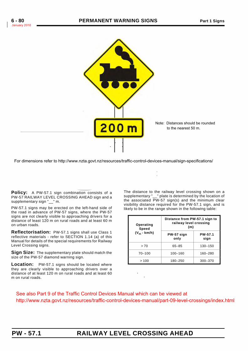
PERMANENT WARNING SIGNS Part 1 SignsJanuary 2010*6 - 80
PW - 57.1 RAILWAY LEVEL CROSSING AHEAD
.
.
.
PW-43Sign Size
Matching Supple*
a b c d . .
..
600 x 600 600 250 96* 50*
750 x 750 750 300 123* 65* 85 Mod.E* 125 D
900 x 900 900 350 144* 75* 100 Mod.E* 150 D
Policy: A PW-57.1 sign combination consists of aPW-57 RAILWAY LEVEL CROSSING AHEAD sign and asupplementary sign "__" m.
PW-57.1 signs may be erected on the left-hand side ofthe road in advance of PW-57 signs, where the PW-57signs are not clearly visible to approaching drivers for adistance of least 120 m on rural roads and at least 60 mon urban roads.
Reflectorisation: PW-57.1 signs shall use Class 1reflective materials - refer to SECTION 1.14 (a) of thisManual for details of the special requirements for RailwayLevel Crossing signs.
Sign Size: The supplementary plate should match thesize of the PW-57 diamond warning sign.
Location: PW-57.1 signs should be located wherethey are clearly visible to approaching drivers over adistance of at least 120 m on rural roads and at least 60m on rural roads.
The distance to the railway level crossing shown on asupplementary "__" plate is determined by the location ofthe associated PW-57 sign(s) and the minimum clearvisibility distance required for the PW-57.1 sign, and islikely to be in the range shown in the following table:
OperatingSpeed
(V85 - km/h)
Distance from PW-57.1 sign torailway level crossing
(m)
PW-57 signonly
PW-57.1sign
> 70 65–85 130–150
70–100 100–160 160–280
> 100 180–250 300–370
..
For dimensions refer to http://www.nzta.govt.nz/resources/traffic-control-devices-manual/sign-specifications/
Note: Distances should be rounded to the nearest 50 m.
See also Part 9 of the Traffic Control Devices Manual which can be viewed at http://www.nzta.govt.nz/resources/traffic-control-devices-manual/part-09-level-crossings/index.html
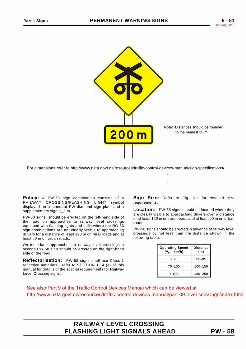
Part 1 Signs PERMANENT WARNING SIGNSJanuary 2010*
6 - 81
RAILWAY LEVEL CROSSINGFLASHING LIGHT SIGNALS AHEAD PW - 58
.
.
.
..
PW-43Sign Size
Matching Supplem.*
a b c d . .
. .
600 x 600 600 250 96* 50*
750 x 750 750 300 123* 65*
900 x 900 900 350 144* 75* 100 Mod.E* 150 D
Policy: A PW-58 sign combination consists of aRAILWAY CROSSING/FLASHING LIGHT symboldisplayed on a standard PW diamond sign plate and asupplementary sign " " m.
PW-58 signs should be erected on the left-hand side ofthe road on approaches to railway level crossingsequipped with flashing lights and bells where the RG-33sign combinations are not clearly visible to approachingdrivers for a distance of least 120 m on rural roads and atleast 60 m on urban roads.
On multi-lane approaches to railway level crossings asecond PW-58 sign should be erected on the right-handside of the road.
Reflectorisation: PW-58 signs shall use Class 1reflective materials - refer to SECTION 1.14 (a) of thismanual for details of the special requirements for RailwayLevel Crossing signs.
Sign Size: Refer to Fig. 6.1 for detailed sizerequirements.
Location: PW-58 signs should be located where theyare clearly visible to approaching drivers over a distanceof at least 120 m on rural roads and at least 60 m on urbanroads.
PW-58 signs should be erected in advance of railway levelcrossings by not less than the distance shown in thefollowing table:
Operating Speed(V85 - km/h)
Distance(m)
< 70 65–85
70–100 100–150
> 100 180–250
For dimensions refer to http://www.nzta.govt.nz/resources/traffic-control-devices-manual/sign-specifications/
Note: Distances should be rounded to the nearest 50 m.
See also Part 9 of the Traffic Control Devices Manual which can be viewed at http://www.nzta.govt.nz/resources/traffic-control-devices-manual/part-09-level-crossings/index.html
PERMANENT WARNING SIGNS Part 1 SignsJanuary 20106 - 82
.
Sign Size(mm) h
600 × 600 40
750 × 750 50
900 × 900 60
(This page is intentionally blank)
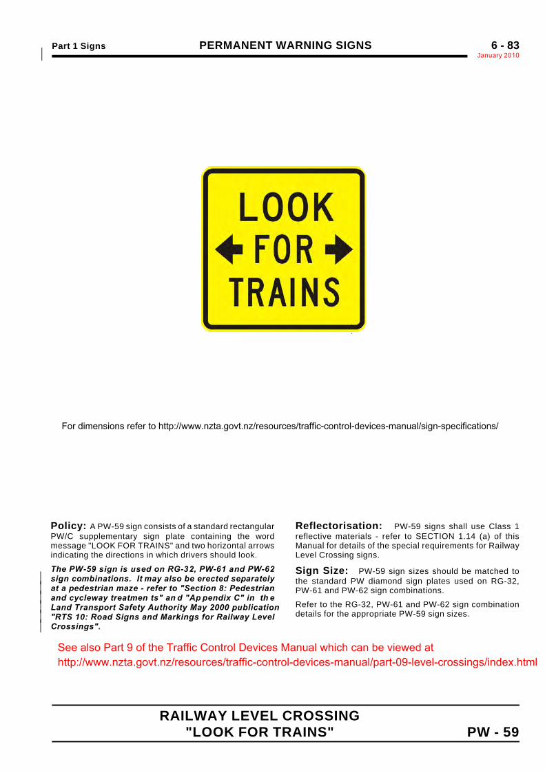
Part 1 Signs PERMANENT WARNING SIGNSJanuary 2010*
6 - 83
RAILWAY LEVEL CROSSING "LOOK FOR TRAINS" PW - 59
. .
Operating Speed(V85 - km/h)
Sign Dimensions(mm)
a b c d e f g h j k m n p
< 70 600 270 201 385 25 600 75 100 D 50 100 C 35 65 110
70–100 750 346 252 482 30 750 95 125 D 63 125 C 45 80 138
> 100 900 412 301 576 35 900 115 150 D 75 150 C 55 95 165
Policy: A PW-59 sign consists of a standard rectangularPW/C supplementary sign plate containing the wordmessage "LOOK FOR TRAINS" and two horizontal arrowsindicating the directions in which drivers should look.
The PW-59 sign is used on RG-32, PW-61 and PW-62sign combinations. It may also be erected separately*at a pedestrian maze - refer to "Section 8: Pedestrian*and cycleway treatmen ts" an d "Ap pendix C" in th e*Land Transport Safety Authority May 2000 publication*"RTS 10: Road Signs and Markings for Railway Level*Crossings".*
Reflectorisation: PW-59 signs shall use Class 1reflective materials - refer to SECTION 1.14 (a) of thisManual for details of the special requirements for RailwayLevel Crossing signs.
Sign Size: PW-59 sign sizes should be matched tothe standard PW diamond sign plates used on RG-32,PW-61 and PW-62 sign combinations.
Refer to the RG-32, PW-61 and PW-62 sign combinationdetails for the appropriate PW-59 sign sizes.
For dimensions refer to http://www.nzta.govt.nz/resources/traffic-control-devices-manual/sign-specifications/
See also Part 9 of the Traffic Control Devices Manual which can be viewed at http://www.nzta.govt.nz/resources/traffic-control-devices-manual/part-09-level-crossings/index.html
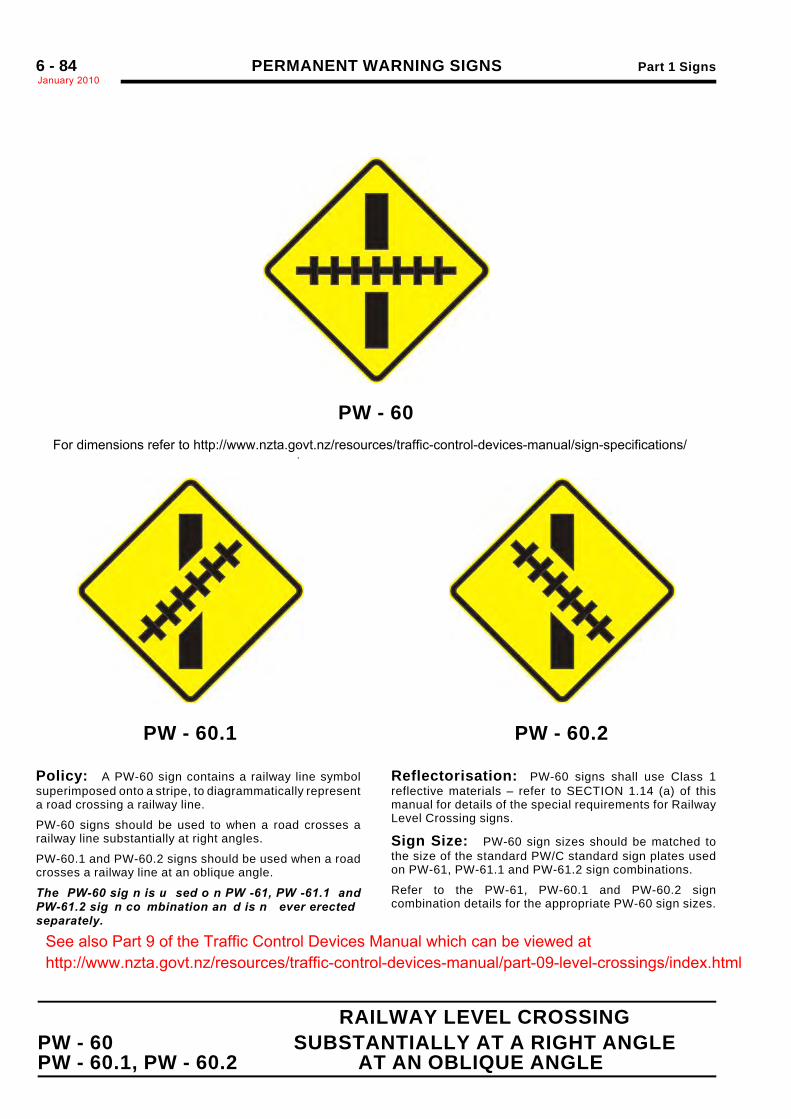
PERMANENT WARNING SIGNS Part 1 SignsJanuary 20106 - 84
RAILWAY LEVEL CROSSINGPW - 60 SUBSTANTIALLY AT A RIGHT ANGLEPW - 60.1, PW - 60.2 AT AN OBLIQUE ANGLE
PW - 60..
PW - 60.1 PW - 60.2
Policy: A PW-60 sign contains a railway line symbolsuperimposed onto a stripe, to diagrammatically representa road crossing a railway line.
PW-60 signs should be used to when a road crosses arailway line substantially at right angles.
PW-60.1 and PW-60.2 signs should be used when a roadcrosses a railway line at an oblique angle.
The PW-60 sig n is u sed o n PW -61, PW -61.1 andPW-61.2 sig n co mbination an d is n ever erectedseparately.
Reflectorisation: PW-60 signs shall use Class 1reflective materials – refer to SECTION 1.14 (a) of thismanual for details of the special requirements for RailwayLevel Crossing signs.
Sign Size: PW-60 sign sizes should be matched tothe size of the standard PW/C standard sign plates usedon PW-61, PW-61.1 and PW-61.2 sign combinations.
Refer to the PW-61, PW-60.1 and PW-60.2 signcombination details for the appropriate PW-60 sign sizes.
For dimensions refer to http://www.nzta.govt.nz/resources/traffic-control-devices-manual/sign-specifications/
See also Part 9 of the Traffic Control Devices Manual which can be viewed at http://www.nzta.govt.nz/resources/traffic-control-devices-manual/part-09-level-crossings/index.html
Part 1 Signs PERMANENT WARNING SIGNSJanuary 2010
6 - 85
.
.
. (This page is intentionally blank)
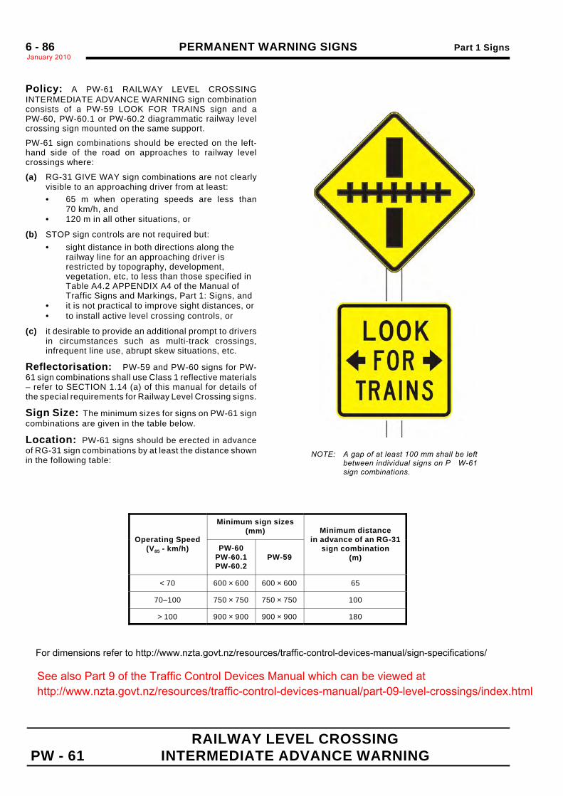
PERMANENT WARNING SIGNS Part 1 SignsJanuary 20106 - 86
RAILWAY LEVEL CROSSING PW - 61 INTERMEDIATE ADVANCE WARNING
NOTE: A gap of at least 100 mm shall be leftbetween individual signs on P W-61sign combinations.
Policy: A PW-61 RAILWAY LEVEL CROSSINGINTERMEDIATE ADVANCE WARNING sign combinationconsists of a PW-59 LOOK FOR TRAINS sign and aPW-60, PW-60.1 or PW-60.2 diagrammatic railway levelcrossing sign mounted on the same support.
PW-61 sign combinations should be erected on the left-hand side of the road on approaches to railway levelcrossings where:
(a) RG-31 GIVE WAY sign combinations are not clearlyvisible to an approaching driver from at least:• 65 m when operating speeds are less than
70 km/h, and• 120 m in all other situations, or
(b) STOP sign controls are not required but:• sight distance in both directions along the
railway line for an approaching driver isrestricted by topography, development,vegetation, etc, to less than those specified inTable A4.2 APPENDIX A4 of the Manual ofTraffic Signs and Markings, Part 1: Signs, and
• it is not practical to improve sight distances, or• to install active level crossing controls, or
(c) it desirable to provide an additional prompt to driversin circumstances such as multi-track crossings,infrequent line use, abrupt skew situations, etc.
Reflectorisation: PW-59 and PW-60 signs for PW-61 sign combinations shall use Class 1 reflective materials– refer to SECTION 1.14 (a) of this manual for details ofthe special requirements for Railway Level Crossing signs.
Sign Size: The minimum sizes for signs on PW-61 signcombinations are given in the table below.
Location: PW-61 signs should be erected in advanceof RG-31 sign combinations by at least the distance shownin the following table:
Operating Speed(V85 - km/h)
Minimum sign sizes(mm) Minimum distance
in advance of an RG-31sign combination
(m)PW-60
PW-60.1PW-60.2
PW-59
< 70 600 × 600 600 × 600 65
70–100 750 × 750 750 × 750 100
> 100 900 × 900 900 × 900 180
For dimensions refer to http://www.nzta.govt.nz/resources/traffic-control-devices-manual/sign-specifications/
See also Part 9 of the Traffic Control Devices Manual which can be viewed at http://www.nzta.govt.nz/resources/traffic-control-devices-manual/part-09-level-crossings/index.html
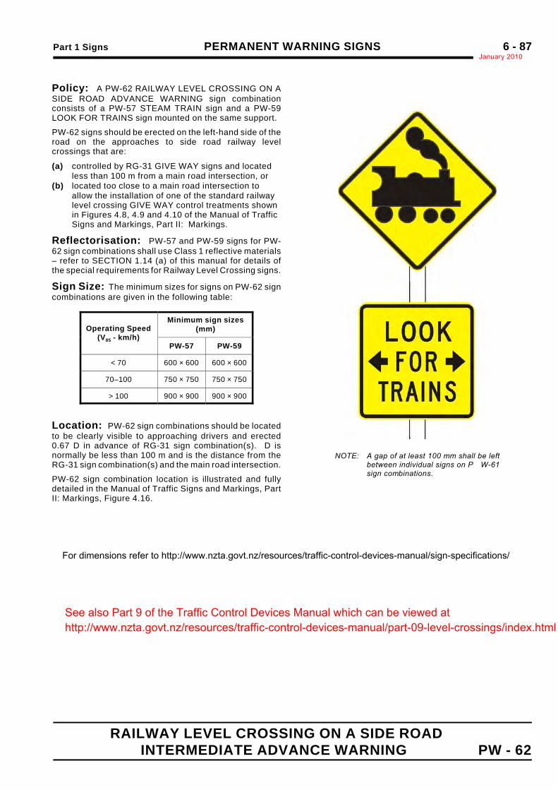
Part 1 Signs PERMANENT WARNING SIGNSJanuary 2010
6 - 87
RAILWAY LEVEL CROSSING ON A SIDE ROAD INTERMEDIATE ADVANCE WARNING PW - 62
NOTE: A gap of at least 100 mm shall be leftbetween individual signs on P W-61sign combinations.
Policy: A PW-62 RAILWAY LEVEL CROSSING ON ASIDE ROAD ADVANCE WARNING sign combinationconsists of a PW-57 STEAM TRAIN sign and a PW-59LOOK FOR TRAINS sign mounted on the same support.
PW-62 signs should be erected on the left-hand side of theroad on the approaches to side road railway levelcrossings that are:
(a) controlled by RG-31 GIVE WAY signs and locatedless than 100 m from a main road intersection, or
(b) located too close to a main road intersection toallow the installation of one of the standard railwaylevel crossing GIVE WAY control treatments shownin Figures 4.8, 4.9 and 4.10 of the Manual of TrafficSigns and Markings, Part II: Markings.
Reflectorisation: PW-57 and PW-59 signs for PW-62 sign combinations shall use Class 1 reflective materials– refer to SECTION 1.14 (a) of this manual for details ofthe special requirements for Railway Level Crossing signs.
Sign Size: The minimum sizes for signs on PW-62 signcombinations are given in the following table:
Operating Speed(V85 - km/h)
Minimum sign sizes(mm)
PW-57 PW-59
< 70 600 × 600 600 × 600
70–100 750 × 750 750 × 750
> 100 900 × 900 900 × 900
Location: PW-62 sign combinations should be locatedto be clearly visible to approaching drivers and erected0.67 D in advance of RG-31 sign combination(s). D isnormally be less than 100 m and is the distance from theRG-31 sign combination(s) and the main road intersection.
PW-62 sign combination location is illustrated and fullydetailed in the Manual of Traffic Signs and Markings, PartII: Markings, Figure 4.16.
For dimensions refer to http://www.nzta.govt.nz/resources/traffic-control-devices-manual/sign-specifications/
See also Part 9 of the Traffic Control Devices Manual which can be viewed at http://www.nzta.govt.nz/resources/traffic-control-devices-manual/part-09-level-crossings/index.html
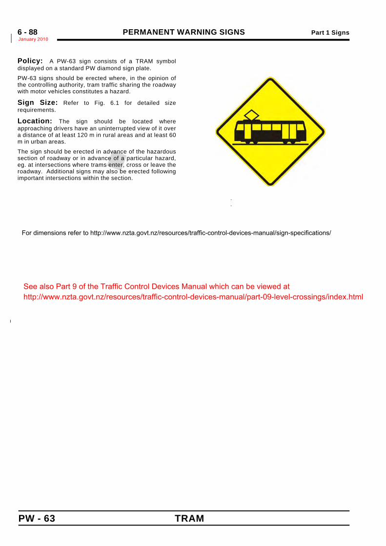
PERMANENT WARNING SIGNS Part 1 SignsJanuary 2010*6 - 88
PW - 63 TRAM
.
.
Policy: A PW-63 sign consists of a TRAM symboldisplayed on a standard PW diamond sign plate.
PW-63 signs should be erected where, in the opinion ofthe controlling authority, tram traffic sharing the roadwaywith motor vehicles constitutes a hazard.
Sign Size: Refer to Fig. 6.1 for detailed sizerequirements.
Location: The sign should be located whereapproaching drivers have an uninterrupted view of it overa distance of at least 120 m in rural areas and at least 60m in urban areas.
The sign should be erected in advance of the hazardoussection of roadway or in advance of a particular hazard,eg. at intersections where trams enter, cross or leave theroadway. Additional signs may also be erected followingimportant intersections within the section.
*
Sign Size*(mm)* h*
600 × 600* 40*
750 × 750* 50*
900 × 900* 60*
For dimensions refer to http://www.nzta.govt.nz/resources/traffic-control-devices-manual/sign-specifications/
See also Part 9 of the Traffic Control Devices Manual which can be viewed at http://www.nzta.govt.nz/resources/traffic-control-devices-manual/part-09-level-crossings/index.html
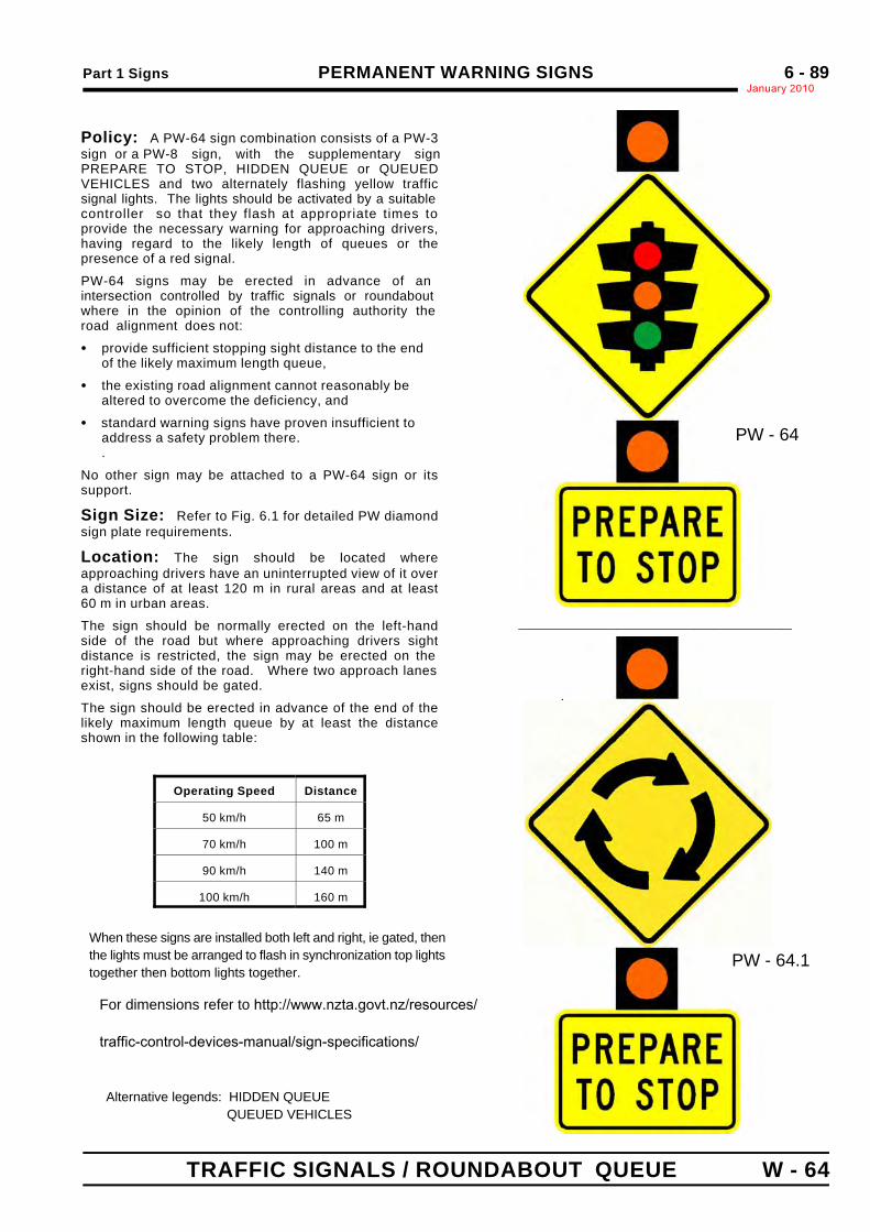
Part 1 Signs PERMANENT WARNING SIGNSJanuary 2010
6 - 89
TRAFFIC SIGNALS / ROUNDABOUT QUEUE W - 64
.
.
Policy: A PW-64 sign combination consists of a PW-3sign or a PW-8 sign, with the supplementary signPREPARE TO STOP, HIDDEN QUEUE or QUEUEDVEHICLES and two alternately flashing yellow trafficsignal lights. The lights should be activated by a suitablecontroller so that they flash at appropriate times toprovide the necessary warning for approaching drivers,having regard to the likely length of queues or thepresence of a red signal.
PW-64 signs may be erected in advance of anintersection controlled by traffic signals or roundabout where in the opinion of the controlling authority the road alignment does not:
C provide sufficient stopping sight distance to the endof the likely maximum length queue,
C the existing road alignment cannot reasonably bealtered to overcome the deficiency, and
C standard warning signs have proven insufficient toaddress a safety problem there..
No other sign may be attached to a PW-64 sign or itssupport.
Sign Size: Refer to Fig. 6.1 for detailed PW diamondsign plate requirements.
Location: The sign should be located whereapproaching drivers have an uninterrupted view of it overa distance of at least 120 m in rural areas and at least60 m in urban areas.
The sign should be normally erected on the left-handside of the road but where approaching drivers sightdistance is restricted, the sign may be erected on the right-hand side of the road. Where two approach lanesexist, signs should be gated.
The sign should be erected in advance of the end of thelikely maximum length queue by at least the distanceshown in the following table:
Operating Speed Distance
50 km/h 65 m
70 km/h 100 m
90 km/h 140 m
100 km/h 160 m
For dimensions refer to http://www.nzta.govt.nz/resources/
traffic-control-devices-manual/sign-specifications/
Alternative legends: HIDDEN QUEUE QUEUED VEHICLES
PW - 64
PW - 64.1
____________________________
When these signs are installed both left and right, ie gated, thenthe lights must be arranged to flash in synchronization top lightstogether then bottom lights together.
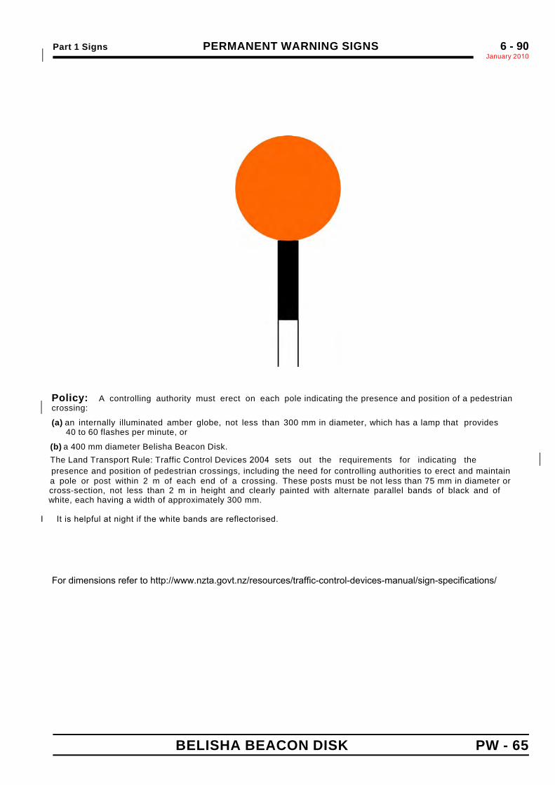
Part 1 Signs PERMANENT WARNING SIGNSJanuary 2010*
6 - 90
BELISHA BEACON DISK PW - 65
Policy: A controlling authority must erect on each pole indicating the presence and position of a pedestriancrossing:*
(a) an internally illuminated amber globe, not less than 300 mm in diameter, which has a lamp that provides 40 to 60 flashes per minute, or
(b) a 400 mm diameter Belisha Beacon Disk. The Land Transport Rule: Traffic Control Devices 2004 sets out the requirements for indicating the *
presence and position of pedestrian crossings, including the need for controlling authorities to erect and maintain a pole or post within 2 m of each end of a crossing. These posts must be not less than 75 mm in diameter or cross-section, not less than 2 m in height and clearly painted with alternate parallel bands of black and of white, each having a width of approximately 300 mm.
I It is helpful at night if the white bands are reflectorised.
For dimensions refer to http://www.nzta.govt.nz/resources/traffic-control-devices-manual/sign-specifications/

Part 1 Signs PERMANENT WARNING SIGNSJanuary 2010*6 - 91
HORIZONTAL CURVE - CHEVRON BOARD PW - 66*
For dimensions refer to http://www.nzta.govt.nz/resources/traffic-control-devices-manual/sign-specifications/
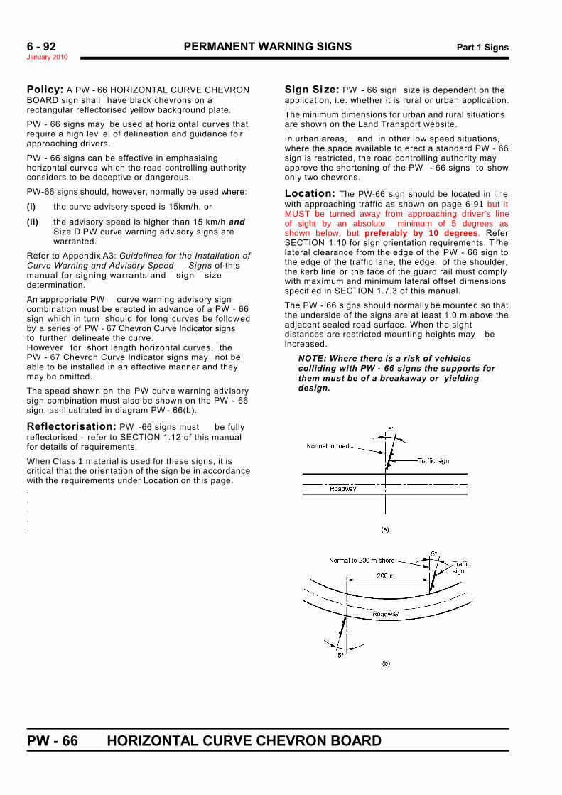
PERMANENT WARNING SIGNS Part 1 SignsJanuary 20106 - 92
PW - 66 HORIZONTAL CURVE CHEVRON BOARD
Policy: A PW - 66 HORIZONTAL CURVE CHEVRONBOARD sign shall have black chevrons on arectangular reflectorised yellow background plate.
PW - 66 signs may be used at horiz ontal curves thatrequire a high lev el of delineation and guidance fo rapproaching drivers.
PW - 66 signs can be effective in emphasisinghorizontal curves which the road controlling authorityconsiders to be deceptive or dangerous.
PW-66 signs should, however, normally be used where: '
(i) the curve advisory speed is 15km/h, or '
(ii) the advisory speed is higher than 15 km/h and 'Size D PW curve warning advisory signs are 'warranted. h '
Refer to Appendix A3: Guidelines for the Installation ofCurve Warning and Advisory Speed Signs of thismanual for signing warrants and sign sizedetermination.
An appropriate PW curve warning advisory signcombination must be erected in advance of a PW - 66sign which in turn should for long curves be followed by a series of PW - 67 Chevron Curve Indicator signsto further delineate the curve. However for short length horizontal curves, thePW - 67 Chevron Curve Indicator signs may not beable to be installed in an effective manner and theymay be omitted.
The speed show n on the PW curve warning adv isorysign combination must also be shown on the PW - 66sign, as illustrated in diagram PW - 66(b).
Reflectorisation: PW -66 signs must be fullyreflectorised - refer to SECTION 1.12 of this manualfor details of requirements.
When Class 1 material is used for these signs, it is critical that the orientation of the sign be in accordancewith the requirements under Location on this page... ...
Sign Size: PW - 66 sign size is dependent on theapplication, i.e. whether it is rural or urban application.
The minimum dimensions for urban and rural situationsare shown on the Land Transport website.
In urban areas, and in other low speed situations,where the space available to erect a standard PW - 66sign is restricted, the road controlling authority mayapprove the shortening of the PW - 66 signs to showonly two chevrons.
Location: The PW-66 sign should be located in linewith approaching traffic as shown on page 6-91 but itMUST be turned away from approaching driver's line of sight by an absolute minimum of 5 degrees as shown below, but preferably by 10 degrees. Refer SECTION 1.10 for sign orientation requirements. T helateral clearance from the edge of the PW - 66 sign tothe edge of the traffic lane, the edge of the shoulder,the kerb line or the face of the guard rail must complywith maximum and minimum lateral offset dimensionsspecified in SECTION 1.7.3 of this manual.
The PW - 66 signs should normally be mounted so thatthe underside of the signs are at least 1.0 m above theadjacent sealed road surface. When the sightdistances are restricted mounting heights may beincreased.
NOTE: Where there is a risk of vehiclescolliding with PW - 66 signs the supports forthem must be of a breakaway or yieldingdesign.
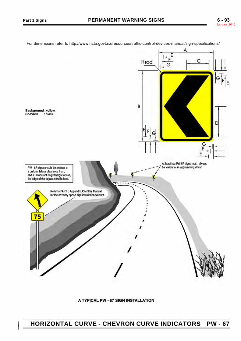
Part 1 Signs PERMANENT WARNING SIGNSJanuary 2010*6 - 93
HORIZONTAL CURVE - CHEVRON CURVE INDICATORS PW - 67**
For dimensions refer to http://www.nzta.govt.nz/resources/traffic-control-devices-manual/sign-specifications/
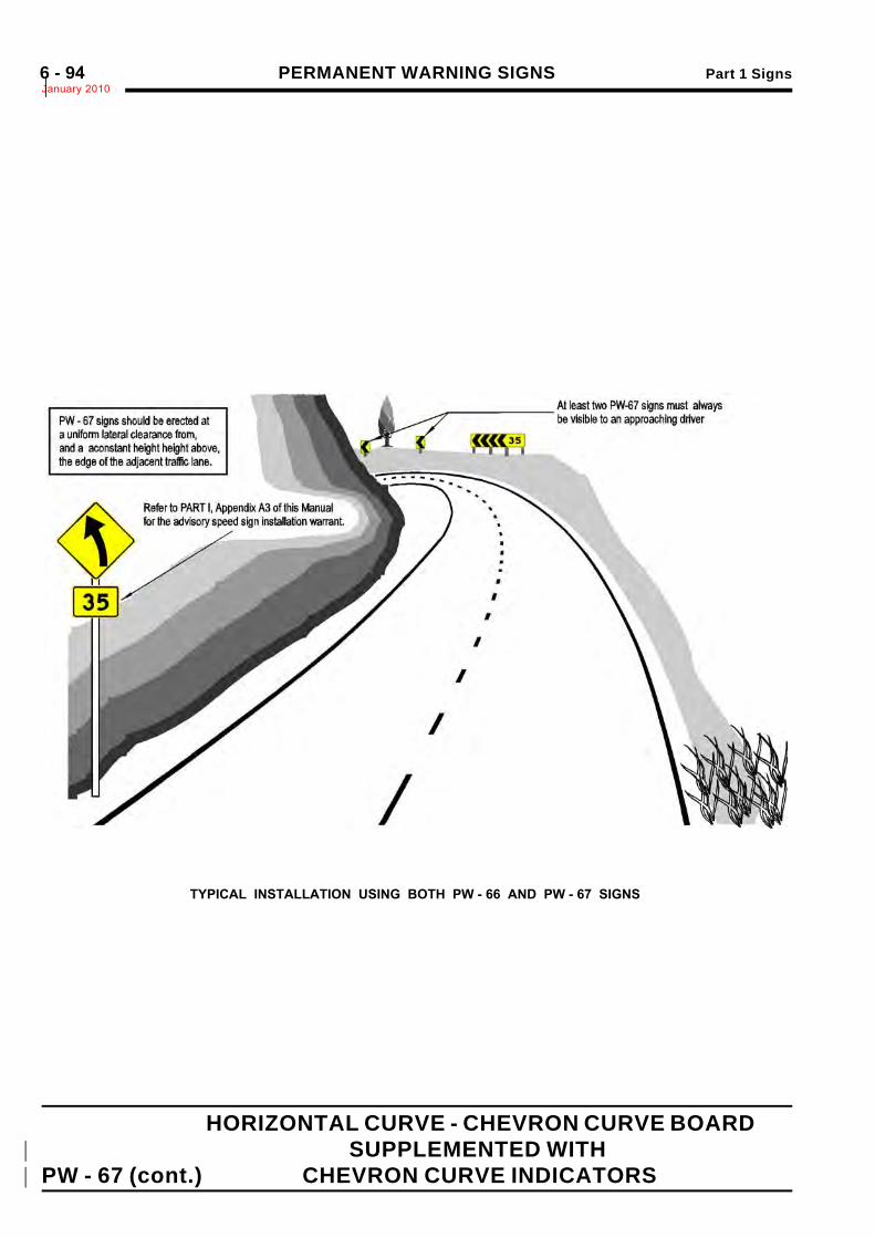
PERMANENT WARNING SIGNS Part 1 SignsJanuary 2010*6 - 94
HORIZONTAL CURVE - CHEVRON CURVE BOARD*
SUPPLEMENTED WITH*
PW - 67 (cont.) CHEVRON CURVE INDICATORS*
TYPICAL INSTALLATION USING BOTH PW - 66 AND PW - 67 SIGNS

PERMANENT WARNING SIGNS Part 1 SignsJanuary 20106 - 95
PW - 67 CHEVRON CURVE INDICATOR
Policy: A PW - 67 CHEVRON CURVE INDICATORsign shall have a black chevron on a rectangularreflectorised yellow background plate.
A series of PW - 67 signs may be used on horizontalcurves where the installation of a PW - 66 s ign is notwarranted but, in the opinion of the road controllingauthority, some additional delineation is requiredthroughout the curve to supplement the PW curv ewarning sign or sign combination. A typical examplesituation is a long, large deflection angle, horizontalcurve.
NOTE: PW - 67 signs must not be usedunless an appropriate PW curve warning signor sign combination is erected.
A series of PW - 67 signs may also be used to furtherdelineate horizontal curves which are signed with botha PW curve warning / advisory speed sign combinationand a PW-66 H orizontal C urve C hevron Sight Boardsign.
Reflectorisation: PW -67 signs must be fullyreflectorised - refer to SECTION 1.12 of this manual fordetails of requirements. Orientation: PW-67 signs MUST be turned away from approaching driver's line of sight by an absoluteminimum of 5 degrees as shown in the diagram on page 6-92 but preferably by 10 degrees.This is especially critical when Class 1 reflectivesheeting is used...
Sign Si ze: PW -67sign siz e is dependent on theapplication, i.e. whether it is rural or urban application.
The minimum sizes for urban and rural situations areshown in the Traffic Control Devices Specifications...
Location: Wherever possible PW - 67 signs shouldbe mounted at a constant height so that the undersideof the signs are at least 1.0 m above the adjacentsealed road surface, and at a constant lateral distancefrom the edge of the adjacent traffic lane, to ensureapproaching drivers are given the best possible v isualindication of the curve’s horizontal and verticalalignment.The lateral clearance from the edge of the PW - 67 signto the edge of the traffic lane, the edge of the shoulder,the kerb line or the face of the guard rail must alsocomply w ith max imum and minimum lateral offsetdimensions specified in SECTION 1.7.3 of this manual.
At least three PW -67 signs should be provided foreach direction of travel. They must be erected at equalspacings on the out side of horiz ontal curv es and insuch a manner that approaching drivers will alwayshave at least tw o in v iew at all times. When the sightdistances are restricted mounting heights may beincreased to have two in view.
PW - 67 signs must be located in the following manner:
(a) The first PW - 67 sign on the approach to ahorizontal curve:
(i) Left Hand Curves• Two-way two-lane roads: On the
prolongation of the centre of the road.• One-way roads: On the prolongation of
the right hand edge line or the right handedge of the sealed road surface if theedge line is not marked.
(ii) Right Hand Curves• On the prolongation of the left hand edge
line or the left hand edge of the sealedroad surface if the edge line is notmarked.
(b) The last PW - 67 sign at the end of a horizontalcurve must be located at the tangent point of thecurve, regardless of whether it is a transitioncurve or a simple circular curve.
(c) Intermediate PW - 67 signs must be equallyspaced between the first and last PW - 67 signslocated as specified in (a) and (b) above.
(d) When a PW - 66 sign is warranted it will replacethe first PW - 67 sign described in (a) above andit must be located as illustrated in the diagramPW - 66(a). Wherever possible the intermediatePW - 67 signs used to further delineate thecurve must be located:
(i) on the outside of the horizontal curve,(ii) at equal spacings between the PW - 66
sign and the last PW - 67 sign located asspecified (b) above at the end of thecurve, and
(iii) in such a manner that approachingdrivers will always have at least two inview at all times.
NOTE: Where there is a risk of vehiclescolliding with PW - 67 signs the supports forthem must be of a breakaway or yieldingdesign.
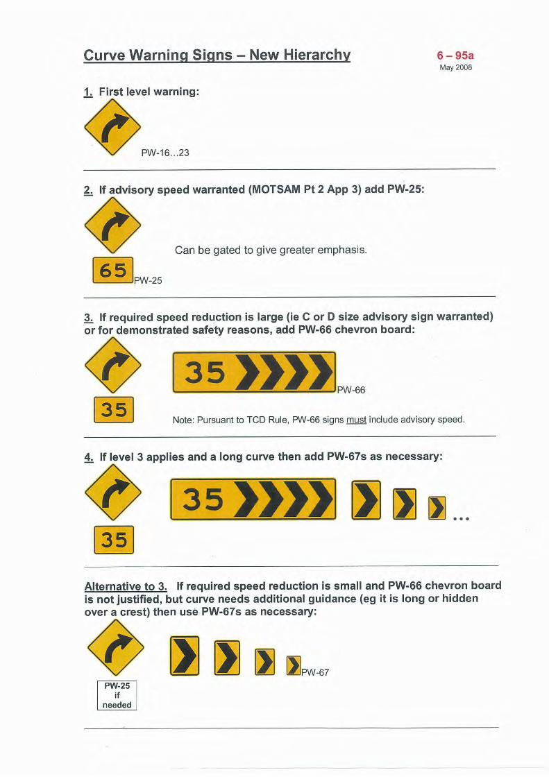
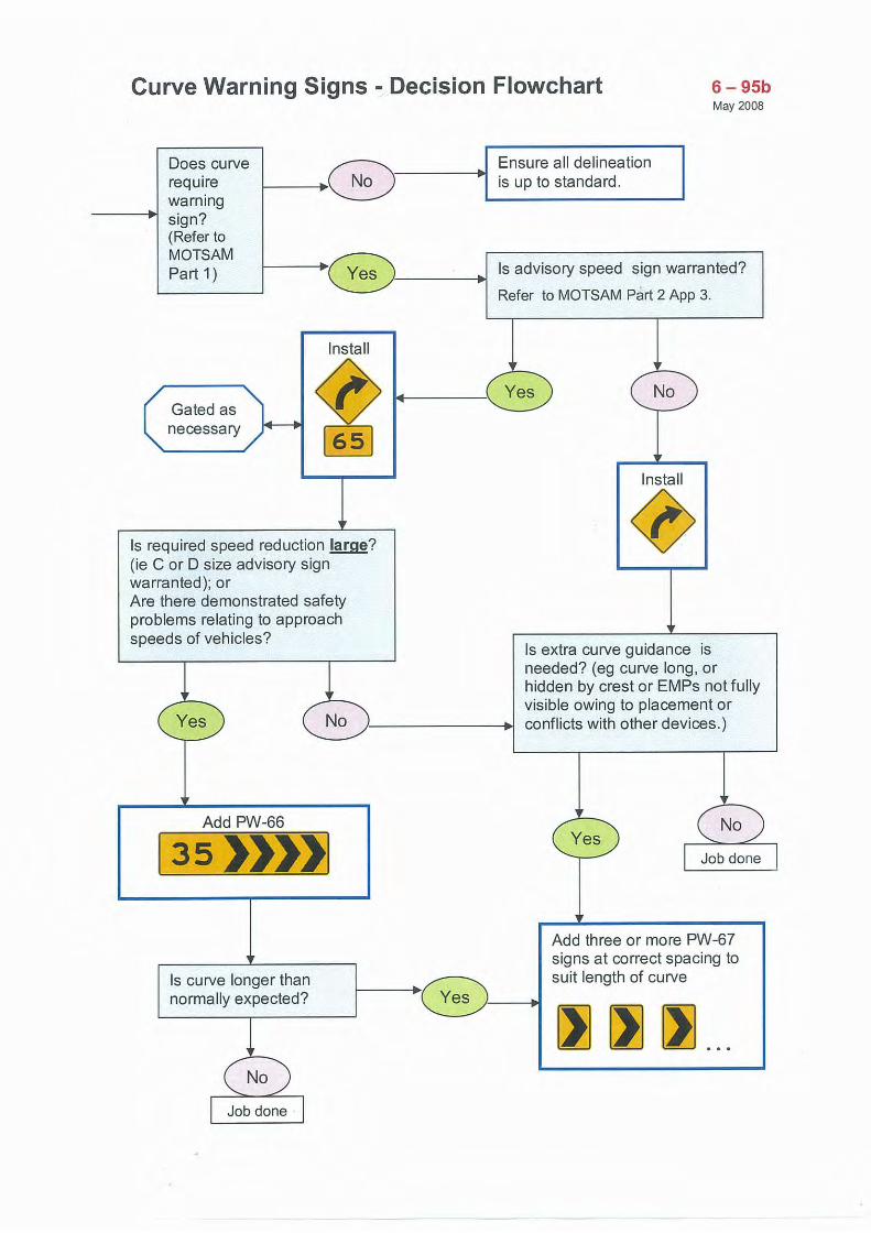
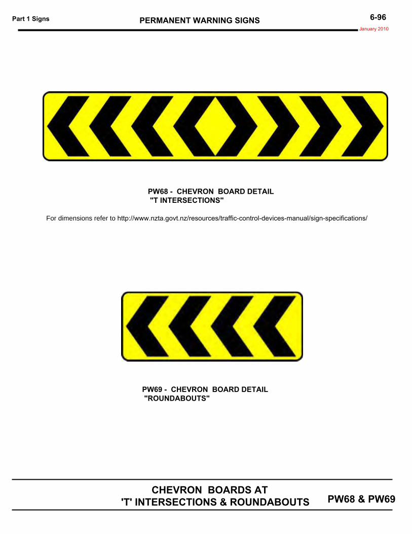
PERMANENT WARNING SIGNSPart 1 Signs January 2010
6-96
PW68 & PW69 CHEVRON BOARDS AT
'T' INTERSECTIONS & ROUNDABOUTS
PW68 - CHEVRON BOARD DETAIL "T INTERSECTIONS"
PW69 - CHEVRON BOARD DETAIL "ROUNDABOUTS"
For dimensions refer to http://www.nzta.govt.nz/resources/traffic-control-devices-manual/sign-specifications/

PERMANENT WARNING SIGNS Part 1: Signs N
6 - 97
:
.
POLICYChevron boards may be used at 'T intersections thatrequire a high level of delineation and guidance forapproaching drivers. Special smaller chevron boardsare used to delineate roundabouts.
PW - 68 Chevron Boards for 'T' intersections andPW - 69 Chevron Boards for roundabouts shall have
Black chevrons on a rectangular reflectorised yellow background plate...
PW - 68 'T' INTERSECTIONS
Chevron boards should be installed at the head of'T' intersections where the intersection is not clearlyvisible to approaching drivers and/or other warningdevices are failing to prevent over-running theintersection. Not usually needed if an ID-5 sign installed.
A 4.8 m long board should normally be used.It should be installed 3.0 m c lear of the left edge of themain road traffic lane and should be w ith its centreoffset 2.0 m to the left of the side road centreline, or in aposition to provide maximum impact for driversapproaching the intersection on the side road.
In urban areas the board length may be reduced to2.4 m long.
PW - 69 ROUNDABOUTSRefer also to Section 3.13 of this part of the Manual:Approaches to Roundabouts.
Chevron boards are desirable at roundaboutsbecause they emphasise both the central island and thechange in travel direction drivers are required to make toenter the roundabout.
The one-way chevron boards used at roundaboutsshould be placed on the central island in the directprojected vision of an approaching driver. At least onechevron board should be provided for each approachlane. Mounting height may be varied to suit the location.
WOODEN SIGHT RAILS..
CHEVRON BOARDS AT 'T' INTERSECTIONSAND AT ROUNDABOUTS
.
.
.
.
.
Orientation of PW-68 and PW-69 . .
___________________________________________________________________________
In situations where guard rails are uneconomic, or conventional delineation devices are not considered appropriate or do not provide the visual guidance expected, wooden sight rails can be constructed as described in RTS 5 Guidelines for rural road markings and delineation. This can be viewed at http://www.landtransport.govt.nz/roads/rts/rts-05.pdf
.January 2010
PW-68 and PW-69 signs should be located in line withapproaching traffic as appropriate, but they MUST be turned away from the approaching driver's line of sight by anabsolute minimum of 5 degrees and preferably by 10 degreesto avoid specular reflection. This is especially critical whenClass 1 reflective material is used.