MOTOROLA M68000 FAMILY - Department of Physics...
92
MOTOROLA INC., 1992 MOTOROLA M68000 FAMILY Programmer’s Reference Manual (Includes CPU32 Instructions)
Transcript of MOTOROLA M68000 FAMILY - Department of Physics...
MOTOROLA INC., 1992
MOTOROLAM68000 FAMILY
Programmer’s Reference Manual
(Includes CPU32 Instructions)

Introduction
1-2
M68000 FAMILY PROGRAMMER’S REFERENCE MANUAL
MOTOROLA
1.1 INTEGER UNIT USER PROGRAMMING MODEL
Figure 1-1 illustrates the integer portion of the user programming model. It consists of thefollowing registers:
• 16 General-Purpose 32-Bit Registers (D7 – D0, A7 – A0)
• 32-Bit Program Counter (PC)
• 8-Bit Condition Code Register (CCR)
.
1.1.1 Data Registers (D7 – D0)
These registers are for bit and bit field (1 – 32 bits), byte (8 bits), word (16 bits), long-word(32 bits), and quad-word (64 bits) operations. They also can be used as index registers.
1.1.2 Address Registers (A7 – A0)
These registers can be used as software stack pointers, index registers, or base addressregisters. The base address registers can be used for word and long-word operations.Register A7 is used as a hardware stack pointer during stacking for subroutine calls andexception handling. In the user programming model, A7 refers to the user stack pointer(USP).
Figure 1-1. M68000 Family User Programming Model
A0A1A2A3A4A5A6
A7 (USP)
PC
D0D1D2D3D4D5D6D7
DATA REGISTERS
ADDRESS REGISTERS
USER STACK POINTERPROGRAM COUNTER
CCRCONDITION CODE REGISTER
01531
01531
0715
031
01531
Introduction
MOTOROLA
M68000 FAMILY PROGRAMMER’S REFERENCE MANUAL
1-3
1.1.3 Program Counter
The PC contains the address of the instruction currently executing. During instructionexecution and exception processing, the processor automatically increments the contentsor places a new value in the PC. For some addressing modes, the PC can be used as apointer for PC relative addressing.
1.1.4 Condition Code Register
Consisting of five bits, the CCR, the status register’s lower byte, is the only portion of thestatus register (SR) available in the user mode. Many integer instructions affect the CCR,indicating the instruction’s result. Program and system control instructions also use certaincombinations of these bits to control program and system flow. The condition codes meettwo criteria: consistency across instructions, uses, and instances and meaningful resultswith no change unless it provides useful information.
Consistency across instructions means that all instructions that are special cases of moregeneral instructions affect the condition codes in the same way. Consistency across usesmeans that conditional instructions test the condition codes similarly and provide the sameresults whether a compare, test, or move instruction sets the condition codes. Consistencyacross instances means that all instances of an instruction affect the condition codes in thesame way.
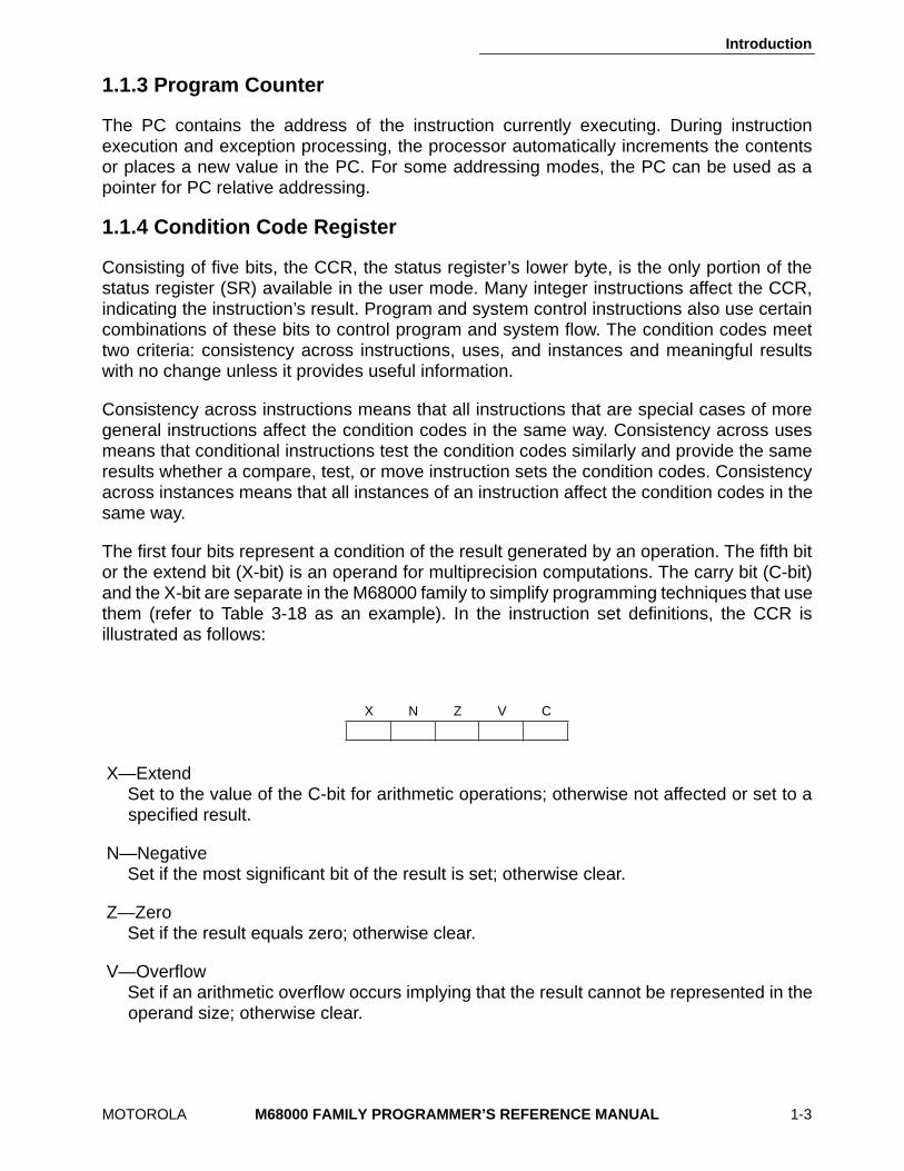
The first four bits represent a condition of the result generated by an operation. The fifth bitor the extend bit (X-bit) is an operand for multiprecision computations. The carry bit (C-bit)and the X-bit are separate in the M68000 family to simplify programming techniques that usethem (refer to Table 3-18 as an example). In the instruction set definitions, the CCR isillustrated as follows:
X—Extend Set to the value of the C-bit for arithmetic operations; otherwise not affected or set to aspecified result.
N—Negative Set if the most significant bit of the result is set; otherwise clear.
Z—Zero Set if the result equals zero; otherwise clear.
V—Overflow Set if an arithmetic overflow occurs implying that the result cannot be represented in theoperand size; otherwise clear.
X N Z V C
Introduction
1-4
M68000 FAMILY PROGRAMMER’S REFERENCE MANUAL
MOTOROLA
C—Carry Set if a carry out of the most significant bit of the operand occurs for an addition, or if aborrow occurs in a subtraction; otherwise clear.
1.2 FLOATING-POINT UNIT USER PROGRAMMING MODEL
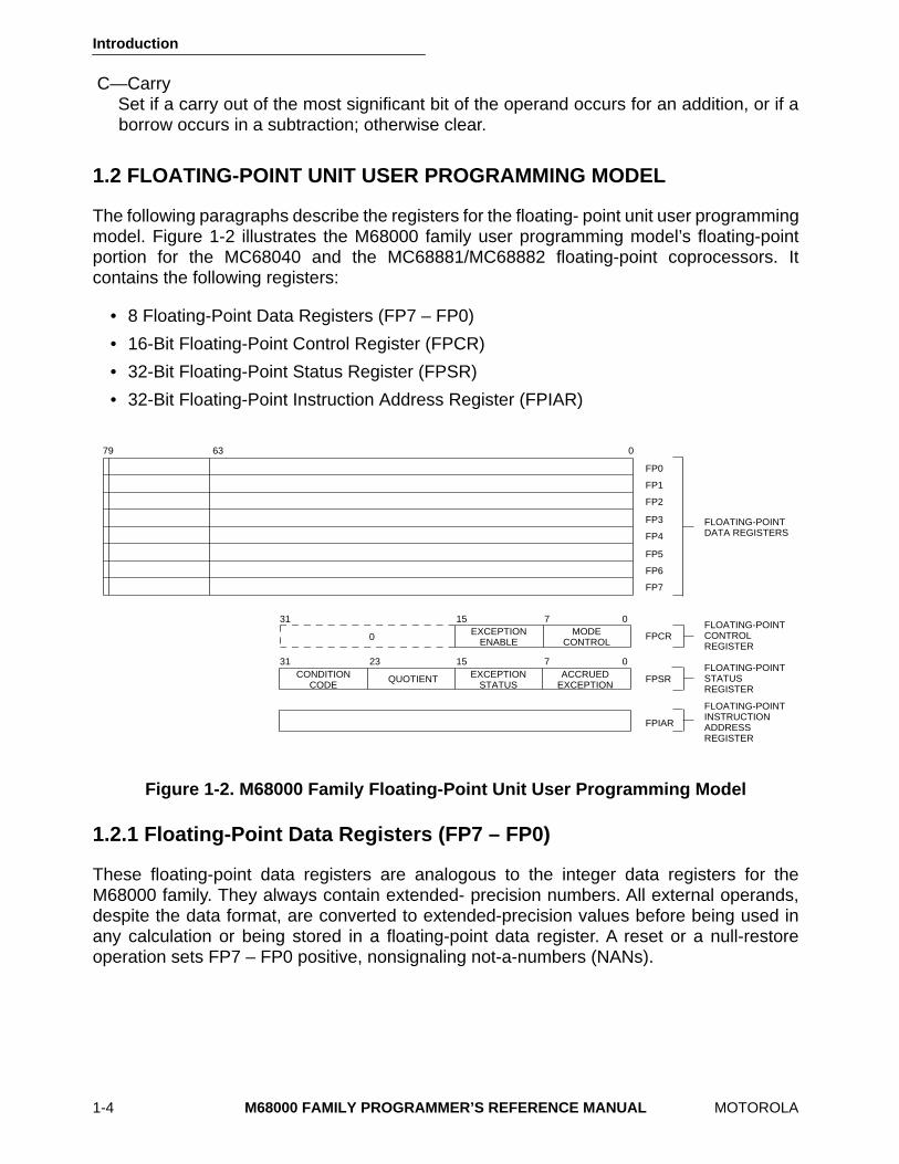
The following paragraphs describe the registers for the floating- point unit user programmingmodel. Figure 1-2 illustrates the M68000 family user programming model’s floating-pointportion for the MC68040 and the MC68881/MC68882 floating-point coprocessors. Itcontains the following registers:
• 8 Floating-Point Data Registers (FP7 – FP0)
• 16-Bit Floating-Point Control Register (FPCR)
• 32-Bit Floating-Point Status Register (FPSR)
• 32-Bit Floating-Point Instruction Address Register (FPIAR)
1.2.1 Floating-Point Data Registers (FP7 – FP0)
These floating-point data registers are analogous to the integer data registers for theM68000 family. They always contain extended- precision numbers. All external operands,despite the data format, are converted to extended-precision values before being used inany calculation or being stored in a floating-point data register. A reset or a null-restoreoperation sets FP7 – FP0 positive, nonsignaling not-a-numbers (NANs).
Figure 1-2. M68000 Family Floating-Point Unit User Programming Model
79 63 0
FP0
FP1
FP3
FP4
FP5
FP6
FP7
FP2
FLOATING-POINTDATA REGISTERS
FPCRFLOATING-POINTCONTROL REGISTER
FPSRFLOATING-POINTSTATUS REGISTER
FPIAR
FLOATING-POINTINSTRUCTION ADDRESS REGISTER
071531MODE
CONTROLEXCEPTION
ENABLE0
EXCEPTIONSTATUS
CONDITIONCODE
QUOTIENT ACCRUEDEXCEPTION
071531 23
Introduction
MOTOROLA M68000 FAMILY PROGRAMMER’S REFERENCE MANUAL 1-25
1.7 ORGANIZATION OF DATA IN REGISTERS
The following paragraphs describe data organization within the data, address, and controlregisters.
1.7.1 Organization of Integer Data Formats in Registers
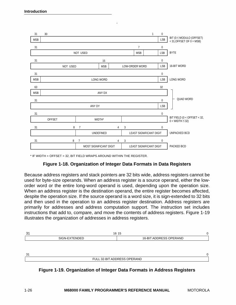
Each integer data register is 32 bits wide. Byte and word operands occupy the lower 8- and16-bit portions of integer data registers, respectively. Long- word operands occupy the entire32 bits of integer data registers. A data register that is either a source or destination operandonly uses or changes the appropriate lower 8 or 16 bits (in byte or word operations,respectively). The remaining high-order portion does not change and goes unused. Theaddress of the least significant bit (LSB) of a long-word integer is zero, and the MSB is 31.For bit fields, the address of the MSB is zero, and the LSB is the width of the register minusone (the offset). If the width of the register plus the offset is greater than 32, the bit fieldwraps around within the register. Figure 1-18 illustrates the organization of various dataformats in the data registers.
An example of a quad word is the product of a 32-bit multiply or the quotient of a 32-bit divideoperation (signed and unsigned). Quad words may be organized in any two integer dataregisters without restrictions on order or pairing. There are no explicit instructions for themanagement of this data format, although the MOVEM instruction can be used to move aquad word into or out of registers.
Binary-coded decimal (BCD) data represents decimal numbers in binary form. Althoughthere are many BCD codes, the BCD instructions of the M68000 family support two formats,packed and unpacked. In these formats, the LSBs consist of a binary number having thenumeric value of the corresponding decimal number. In the unpacked BCD format, a bytedefines one decimal number that has four LSBs containing the binary value and fourundefined MSBs. Each byte of the packed BCD format contains two decimal numbers; theleast significant four bits contain the least significant decimal number and the mostsignificant four bits contain the most significant decimal number.
Introduction
1-26 M68000 FAMILY PROGRAMMER’S REFERENCE MANUAL MOTOROLA
.
Because address registers and stack pointers are 32 bits wide, address registers cannot beused for byte-size operands. When an address register is a source operand, either the low-order word or the entire long-word operand is used, depending upon the operation size.When an address register is the destination operand, the entire register becomes affected,despite the operation size. If the source operand is a word size, it is sign-extended to 32 bitsand then used in the operation to an address register destination. Address registers areprimarily for addresses and address computation support. The instruction set includesinstructions that add to, compare, and move the contents of address registers. Figure 1-19illustrates the organization of addresses in address registers.
Figure 1-19. Organization of Integer Data Formats in Address Registers
Figure 1-18. Organization of Integer Data Formats in Data Registers
31 16 15 0
SIGN-EXTENDED 16-BIT ADDRESS OPERAND
31 0
FULL 32-BIT ADDRESS OPERAND
LSBMSB
1 031 30BIT (0 MODULO (OFFSET) < 31,OFFSET OF 0 = MSB)
<_
0731
BYTE
031
16-BIT WORD
031
LONG WORD
MSB
3263
QUAD WORD031
OFFSET
031BIT FIELD (0 < OFFSET < 32, 0 < WIDTH 32)
7 0331
031 7
15
LOW-ORDER WORD
LONG WORD
ANY DX
LSBANY DY
WIDTH* <_
UNPACKED BCD
PACKED BCD
UNDEFINED LEAST SIGNIFICANT DIGIT
4
34
LEAST SIGNIFICANT DIGITMOST SIGNIFICANT DIGIT
* IF WIDTH + OFFSET > 32, BIT FIELD WRAPS AROUND WITHIN THE REGISTER.
8
8
LSB
LSB
MSB
MSB
LSBMSBNOT USED
NOT USED
Introduction
MOTOROLA M68000 FAMILY PROGRAMMER’S REFERENCE MANUAL 1-27
Control registers vary in size according to function. Some control registers have undefinedbits reserved for future definition by Motorola. Those particular bits read as zeros and mustbe written as zeros for future compatibility.
All operations to the SR and CCR are word-size operations. For all CCR operations, theupper byte is read as all zeros and is ignored when written, despite privilege mode. Thealternate function code registers, supervisor function code (SFC) and data function code(DFC), are 32-bit registers with only bits 0P2 implemented. These bits contain the addressspace values for the read or write operands of MOVES, PFLUSH, and PTEST instructions.Values transfer to and from the SFC and DFC by using the MOVEC instruction. These arelong-word transfers; the upper 29 bits are read as zeros and are ignored when written.
1.7.2 Organization of Integer Data Formats in Memory
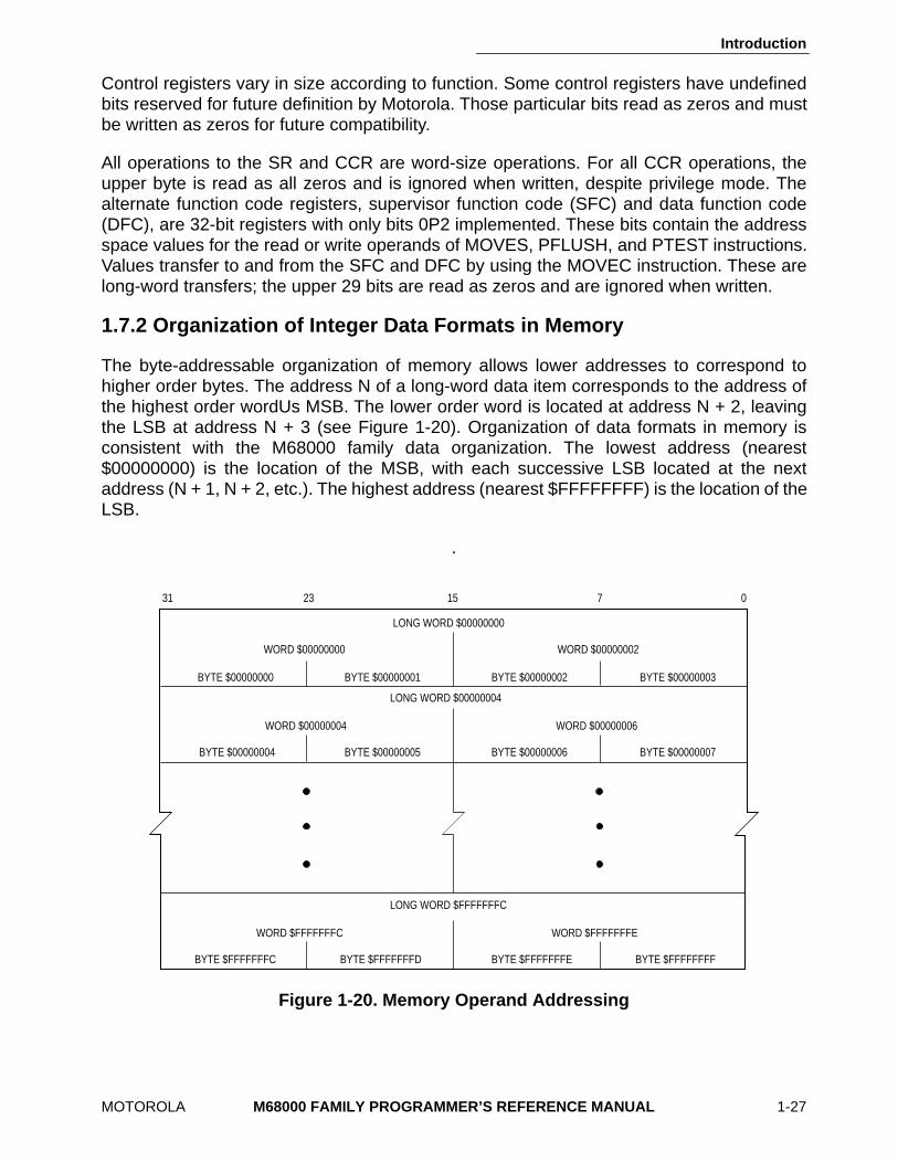
The byte-addressable organization of memory allows lower addresses to correspond tohigher order bytes. The address N of a long-word data item corresponds to the address ofthe highest order wordUs MSB. The lower order word is located at address N + 2, leavingthe LSB at address N + 3 (see Figure 1-20). Organization of data formats in memory isconsistent with the M68000 family data organization. The lowest address (nearest$00000000) is the location of the MSB, with each successive LSB located at the nextaddress (N + 1, N + 2, etc.). The highest address (nearest $FFFFFFFF) is the location of theLSB.
.
Figure 1-20. Memory Operand Addressing
31 23 15 7 0
BYTE $00000000
WORD $00000000
LONG WORD $00000000
BYTE $00000001 BYTE $00000002 BYTE $00000003
WORD $00000002
BYTE $00000004
WORD $00000004
LONG WORD $00000004
BYTE $00000005 BYTE $00000006 BYTE $00000007
WORD $00000006
BYTE $FFFFFFFC
WORD $FFFFFFFC
LONG WORD $FFFFFFFC
BYTE $FFFFFFFD BYTE $FFFFFFFE BYTE $FFFFFFFF
WORD $FFFFFFFE
MOTOROLA
M68000 FAMILY PROGRAMMER’S REFERENCE MANUAL
2-1
SECTION 2ADDRESSING CAPABILITIES
Most operations take asource operand and destination operand, compute them, and storethe result in the destination location. Single-operand operations take a destination operand,compute it, and store the result in the destination location. External microprocessorreferences to memory are either program references that refer to program space or datareferences that refer to data space. They access either instruction words or operands (dataitems) for an instruction. Program space is the section of memory that contains the programinstructions and any immediate data operands residing in the instruction stream. Data spaceis the section of memory that contains the program data. Data items in the instruction streamcan be accessed with the program counter relative addressing modes; these accessesclassify as program references.
2.1 INSTRUCTION FORMAT
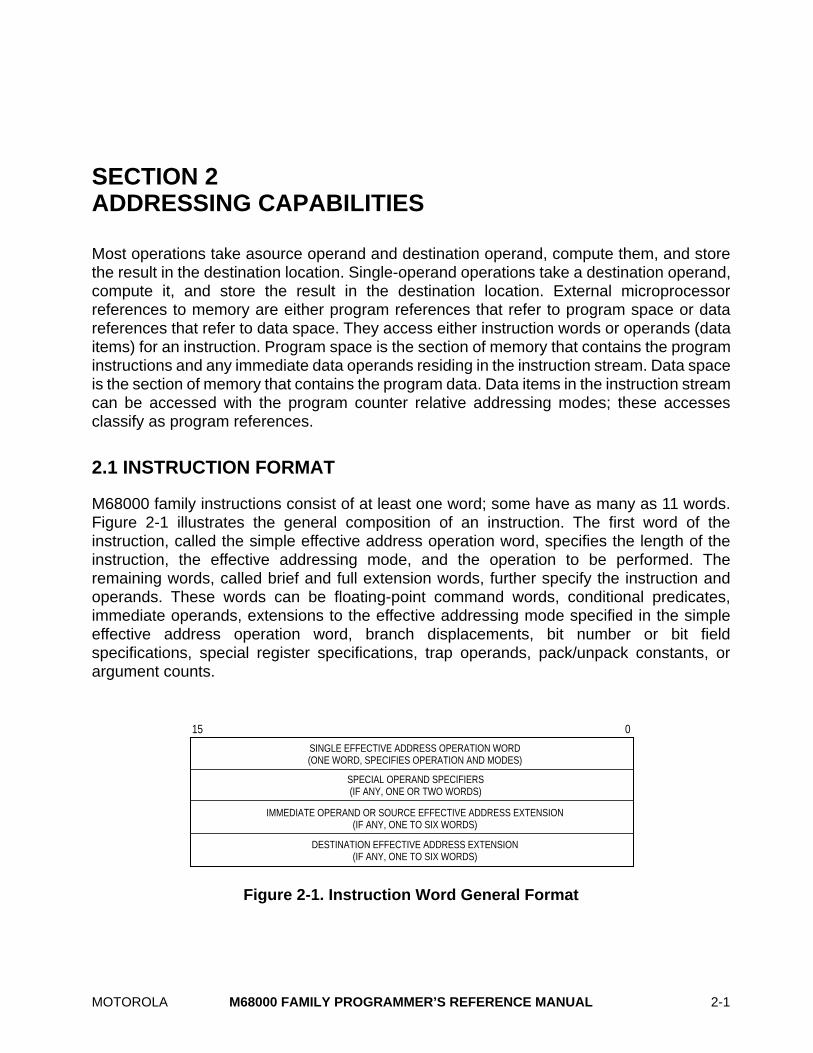
M68000 family instructions consist of at least one word; some have as many as 11 words.Figure 2-1 illustrates the general composition of an instruction. The first word of theinstruction, called the simple effective address operation word, specifies the length of theinstruction, the effective addressing mode, and the operation to be performed. Theremaining words, called brief and full extension words, further specify the instruction andoperands. These words can be floating-point command words, conditional predicates,immediate operands, extensions to the effective addressing mode specified in the simpleeffective address operation word, branch displacements, bit number or bit fieldspecifications, special register specifications, trap operands, pack/unpack constants, orargument counts.
Figure 2-1. Instruction Word General Format
SINGLE EFFECTIVE ADDRESS OPERATION WORD (ONE WORD, SPECIFIES OPERATION AND MODES)
SPECIAL OPERAND SPECIFIERS (IF ANY, ONE OR TWO WORDS)
IMMEDIATE OPERAND OR SOURCE EFFECTIVE ADDRESS EXTENSION (IF ANY, ONE TO SIX WORDS)
DESTINATION EFFECTIVE ADDRESS EXTENSION (IF ANY, ONE TO SIX WORDS)
15 0
Addressing Capabilities
2-2
M68000 FAMILY PROGRAMMER’S REFERENCE MANUAL
MOTOROLA
An instruction specifies the function to be performed with an operation code and defines thelocation of every operand. Instructions specify an operand location by register specification,the instruction’s register field holds the register’s number; by effective address, theinstruction’s effective address field contains addressing mode information; or by implicitreference, the definition of the instruction implies the use of specific registers.
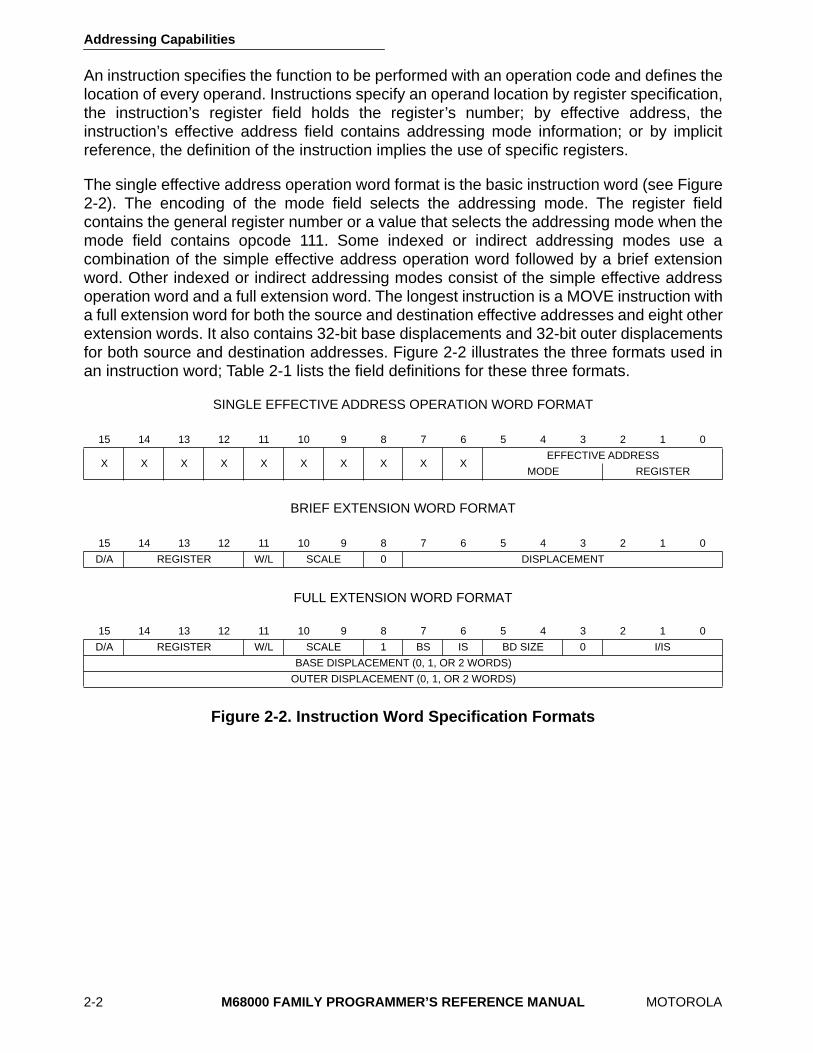
The single effective address operation word format is the basic instruction word (see Figure2-2). The encoding of the mode field selects the addressing mode. The register fieldcontains the general register number or a value that selects the addressing mode when themode field contains opcode 111. Some indexed or indirect addressing modes use acombination of the simple effective address operation word followed by a brief extensionword. Other indexed or indirect addressing modes consist of the simple effective addressoperation word and a full extension word. The longest instruction is a MOVE instruction witha full extension word for both the source and destination effective addresses and eight otherextension words. It also contains 32-bit base displacements and 32-bit outer displacementsfor both source and destination addresses. Figure 2-2 illustrates the three formats used inan instruction word; Table 2-1 lists the field definitions for these three formats.
SINGLE EFFECTIVE ADDRESS OPERATION WORD FORMAT
BRIEF EXTENSION WORD FORMAT
FULL EXTENSION WORD FORMAT
Figure 2-2. Instruction Word Specification Formats
15 14 13 12 11 10 9 8 7 6 5 4 3 2 1 0
X X X X X X X X X XEFFECTIVE ADDRESS
MODE REGISTER
15 14 13 12 11 10 9 8 7 6 5 4 3 2 1 0
D/A REGISTER W/L SCALE 0 DISPLACEMENT
15 14 13 12 11 10 9 8 7 6 5 4 3 2 1 0
D/A REGISTER W/L SCALE 1 BS IS BD SIZE 0 I/IS
BASE DISPLACEMENT (0, 1, OR 2 WORDS)
OUTER DISPLACEMENT (0, 1, OR 2 WORDS)
Addressing Capabilities
MOTOROLA
M68000 FAMILY PROGRAMMER’S REFERENCE MANUAL
2-3
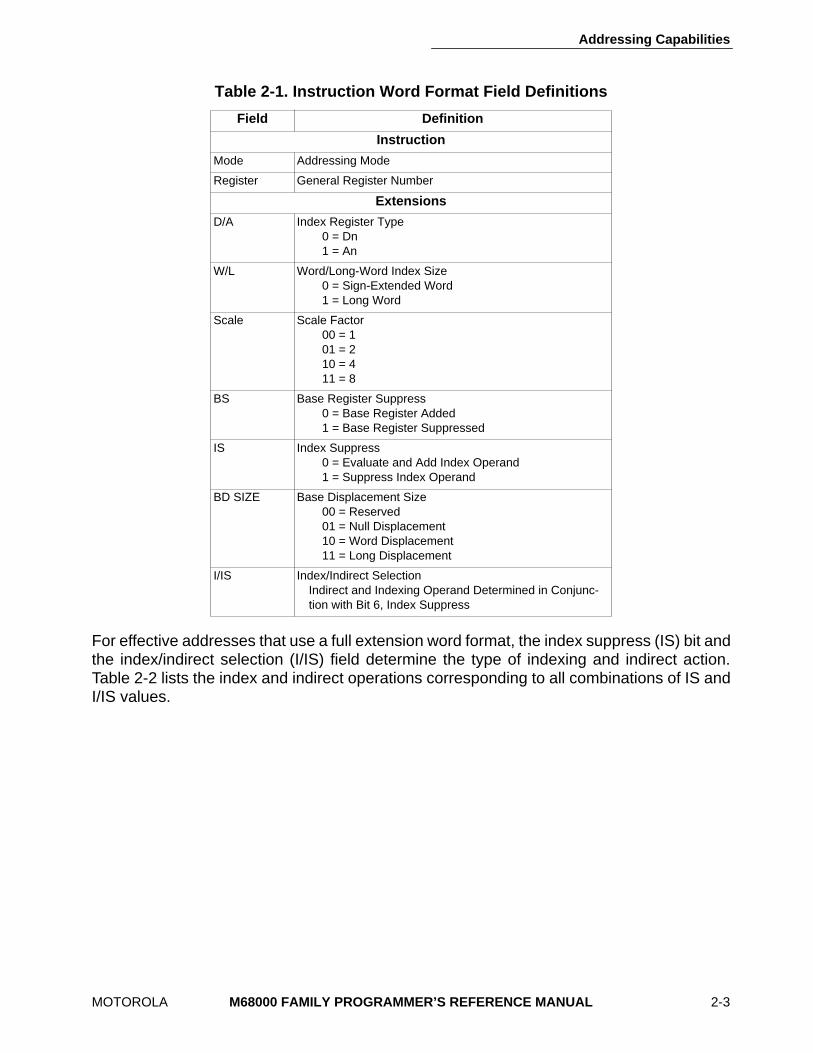
For effective addresses that use a full extension word format, the index suppress (IS) bit andthe index/indirect selection (I/IS) field determine the type of indexing and indirect action.Table 2-2 lists the index and indirect operations corresponding to all combinations of IS andI/IS values.
Table 2-1. Instruction Word Format Field Definitions
Field Definition
Instruction
Mode Addressing Mode
Register General Register Number
Extensions
D/A Index Register Type0 = Dn1 = An
W/L Word/Long-Word Index Size0 = Sign-Extended Word1 = Long Word
Scale Scale Factor00 = 101 = 210 = 411 = 8
BS Base Register Suppress0 = Base Register Added1 = Base Register Suppressed
IS Index Suppress0 = Evaluate and Add Index Operand1 = Suppress Index Operand
BD SIZE Base Displacement Size00 = Reserved01 = Null Displacement10 = Word Displacement11 = Long Displacement
I/IS Index/Indirect SelectionIndirect and Indexing Operand Determined in Conjunc-tion with Bit 6, Index Suppress
Addressing Capabilities
2-4
M68000 FAMILY PROGRAMMER’S REFERENCE MANUAL
MOTOROLA
2.2 EFFECTIVE ADDRESSING MODES
Besides the operation code, which specifies the function to be performed, an instructiondefines the location of every operand for the function. Instructions specify an operandlocation in one of three ways. A register field within an instruction can specify the register tobe used; an instruction’s effective address field can contain addressing mode information;or the instruction’s definition can imply the use of a specific register. Other fields within theinstruction specify whether the register selected is an address or data register and how theregister is to be used.
Section 1 Introduction
contains detailed register descriptions.
An instruction’s addressing mode specifies the value of an operand, a register that containsthe operand, or how to derive the effective address of an operand in memory. Eachaddressing mode has an assembler syntax. Some instructions imply the addressing modefor an operand. These instructions include the appropriate fields for operands that use onlyone addressing mode.
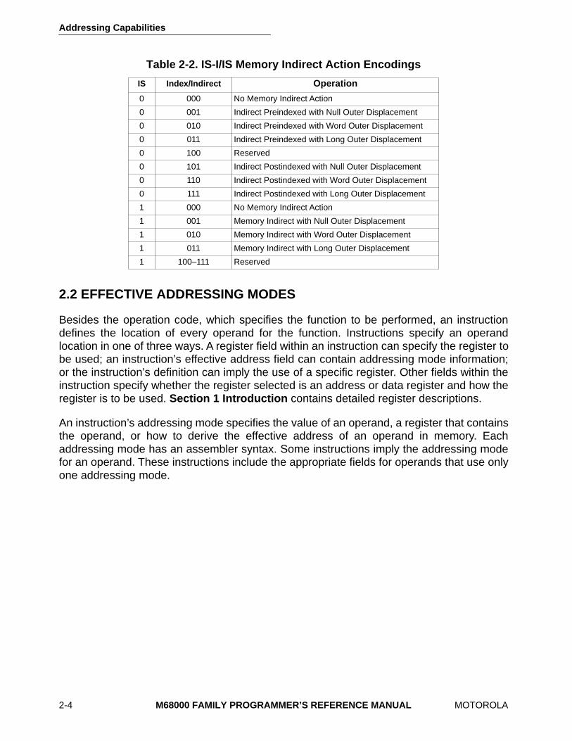
Table 2-2. IS-I/IS Memory Indirect Action Encodings
IS Index/Indirect
Operation
0 000 No Memory Indirect Action
0 001 Indirect Preindexed with Null Outer Displacement
0 010 Indirect Preindexed with Word Outer Displacement
0 011 Indirect Preindexed with Long Outer Displacement
0 100 Reserved
0 101 Indirect Postindexed with Null Outer Displacement
0 110 Indirect Postindexed with Word Outer Displacement
0 111 Indirect Postindexed with Long Outer Displacement
1 000 No Memory Indirect Action
1 001 Memory Indirect with Null Outer Displacement
1 010 Memory Indirect with Word Outer Displacement
1 011 Memory Indirect with Long Outer Displacement
1 100–111 Reserved
Addressing Capabilities
MOTOROLA
M68000 FAMILY PROGRAMMER’S REFERENCE MANUAL
2-5
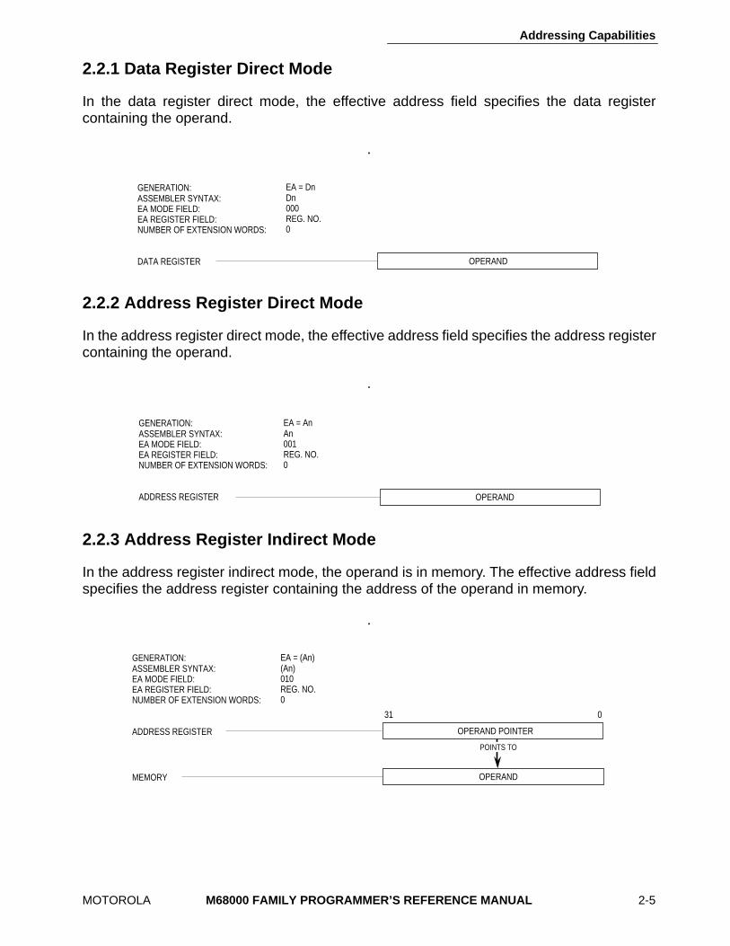
2.2.1 Data Register Direct Mode
In the data register direct mode, the effective address field specifies the data registercontaining the operand.
.
2.2.2 Address Register Direct Mode
In the address register direct mode, the effective address field specifies the address registercontaining the operand.
.
2.2.3 Address Register Indirect Mode
In the address register indirect mode, the operand is in memory. The effective address fieldspecifies the address register containing the address of the operand in memory.
.
EA = DnDn000REG. NO.0
GENERATION:ASSEMBLER SYNTAX:EA MODE FIELD:EA REGISTER FIELD:NUMBER OF EXTENSION WORDS:
DATA REGISTER OPERAND
OPERAND
EA = AnAn001REG. NO.0
GENERATION:ASSEMBLER SYNTAX:EA MODE FIELD:EA REGISTER FIELD:NUMBER OF EXTENSION WORDS:
ADDRESS REGISTER
MEMORY
EA = (An)(An)010REG. NO.0
OPERAND
OPERAND POINTER
031
GENERATION:ASSEMBLER SYNTAX:EA MODE FIELD:EA REGISTER FIELD:NUMBER OF EXTENSION WORDS:
ADDRESS REGISTER
POINTS TO
Addressing Capabilities
2-6
M68000 FAMILY PROGRAMMER’S REFERENCE MANUAL
MOTOROLA
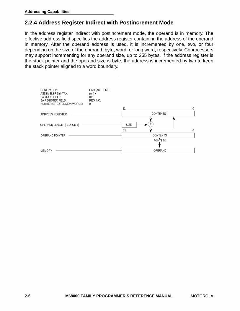
2.2.4 Address Register Indirect with Postincrement Mode
In the address register indirect with postincrement mode, the operand is in memory. Theeffective address field specifies the address register containing the address of the operandin memory. After the operand address is used, it is incremented by one, two, or fourdepending on the size of the operand: byte, word, or long word, respectively. Coprocessorsmay support incrementing for any operand size, up to 255 bytes. If the address register isthe stack pointer and the operand size is byte, the address is incremented by two to keepthe stack pointer aligned to a word boundary.
.
EA = (An) + SIZE(An) +011REG. NO.0
GENERATION:ASSEMBLER SYNTAX:EA MODE FIELD:EA REGISTER FIELD:NUMBER OF EXTENSION WORDS:
ADDRESS REGISTER CONTENTS
031
CONTENTS
031
OPERAND POINTER
OPERAND LENGTH ( 1, 2, OR 4) SIZE
MEMORY OPERAND
POINTS TO
+
Addressing Capabilities
MOTOROLA
M68000 FAMILY PROGRAMMER’S REFERENCE MANUAL
2-7
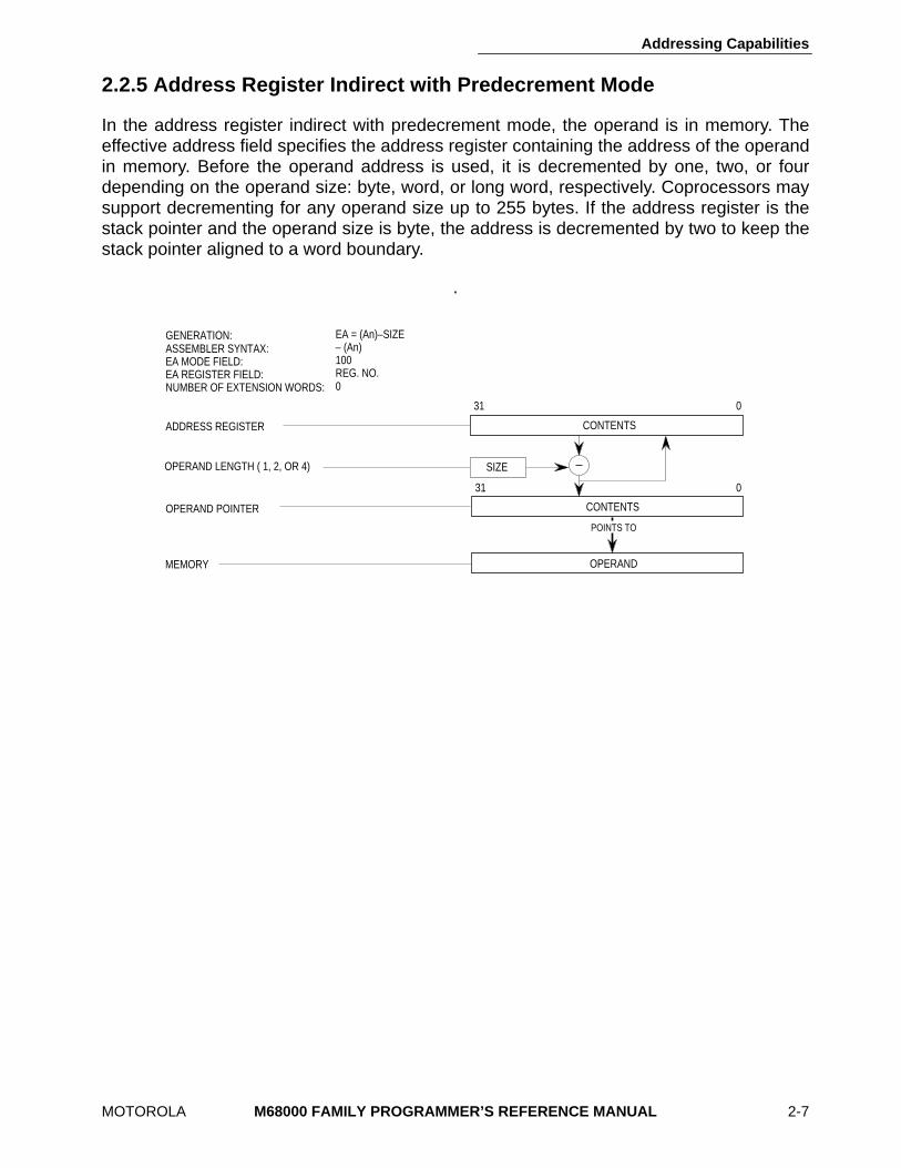
2.2.5 Address Register Indirect with Predecrement Mode
In the address register indirect with predecrement mode, the operand is in memory. Theeffective address field specifies the address register containing the address of the operandin memory. Before the operand address is used, it is decremented by one, two, or fourdepending on the operand size: byte, word, or long word, respectively. Coprocessors maysupport decrementing for any operand size up to 255 bytes. If the address register is thestack pointer and the operand size is byte, the address is decremented by two to keep thestack pointer aligned to a word boundary.
.
CONTENTS
031
CONTENTS
031
EA = (An)–SIZE– (An)100REG. NO.0
OPERAND POINTER
OPERAND LENGTH ( 1, 2, OR 4)
GENERATION:ASSEMBLER SYNTAX:EA MODE FIELD:EA REGISTER FIELD:NUMBER OF EXTENSION WORDS:
ADDRESS REGISTER
SIZE
MEMORY OPERAND
POINTS TO
Addressing Capabilities
2-8
M68000 FAMILY PROGRAMMER’S REFERENCE MANUAL
MOTOROLA
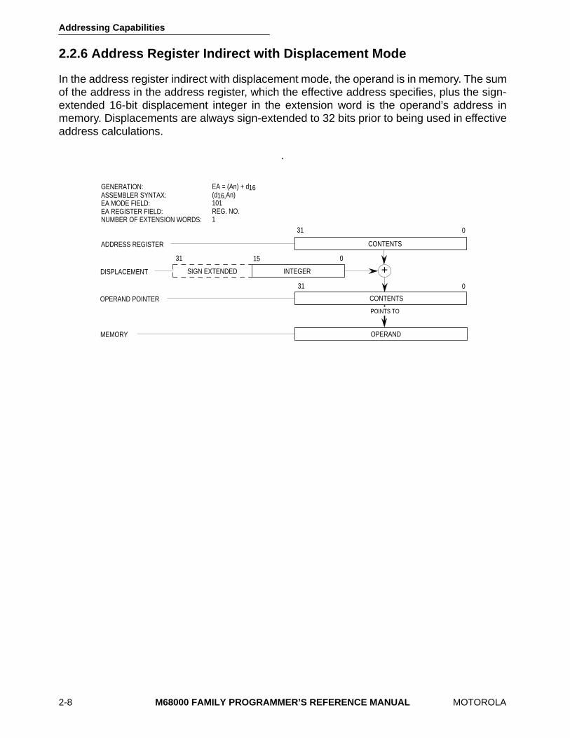
2.2.6 Address Register Indirect with Displacement Mode
In the address register indirect with displacement mode, the operand is in memory. The sumof the address in the address register, which the effective address specifies, plus the sign-extended 16-bit displacement integer in the extension word is the operand’s address inmemory. Displacements are always sign-extended to 32 bits prior to being used in effectiveaddress calculations.
.
+DISPLACEMENT
OPERAND POINTER
EA = (An) + d(d An)101REG. NO.1
CONTENTS
CONTENTS
0
0
31
31
SIGN EXTENDED
31 0
INTEGER
1616,
15
GENERATION:ASSEMBLER SYNTAX:EA MODE FIELD:EA REGISTER FIELD:NUMBER OF EXTENSION WORDS:
ADDRESS REGISTER
MEMORY OPERAND
POINTS TO
Addressing Capabilities
MOTOROLA
M68000 FAMILY PROGRAMMER’S REFERENCE MANUAL
2-9
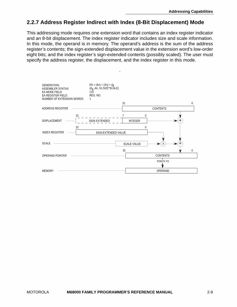
2.2.7 Address Register Indirect with Index (8-Bit Displacement) Mode
This addressing mode requires one extension word that contains an index register indicatorand an 8-bit displacement. The index register indicator includes size and scale information.In this mode, the operand is in memory. The operand’s address is the sum of the addressregister’s contents; the sign-extended displacement value in the extension word’s low-ordereight bits; and the index register’s sign-extended contents (possibly scaled). The user mustspecify the address register, the displacement, and the index register in this mode.
.
+
+X
INTEGERSIGN EXTENDED
SIGN-EXTENDED VALUE
SCALE VALUE
CONTENTS
0
7 031
31 0
31 0
DISPLACEMENT
INDEX REGISTER
SCALE
OPERAND POINTER
31
EA = (An) + (Xn) + d(d ,An, Xn.SIZE*SCALE)8
8
110REG. NO.1
CONTENTS
GENERATION:ASSEMBLER SYNTAX:EA MODE FIELD:EA REGISTER FIELD:NUMBER OF EXTENSION WORDS:
ADDRESS REGISTER
MEMORY OPERAND
POINTS TO
Addressing Capabilities
2-10
M68000 FAMILY PROGRAMMER’S REFERENCE MANUAL
MOTOROLA
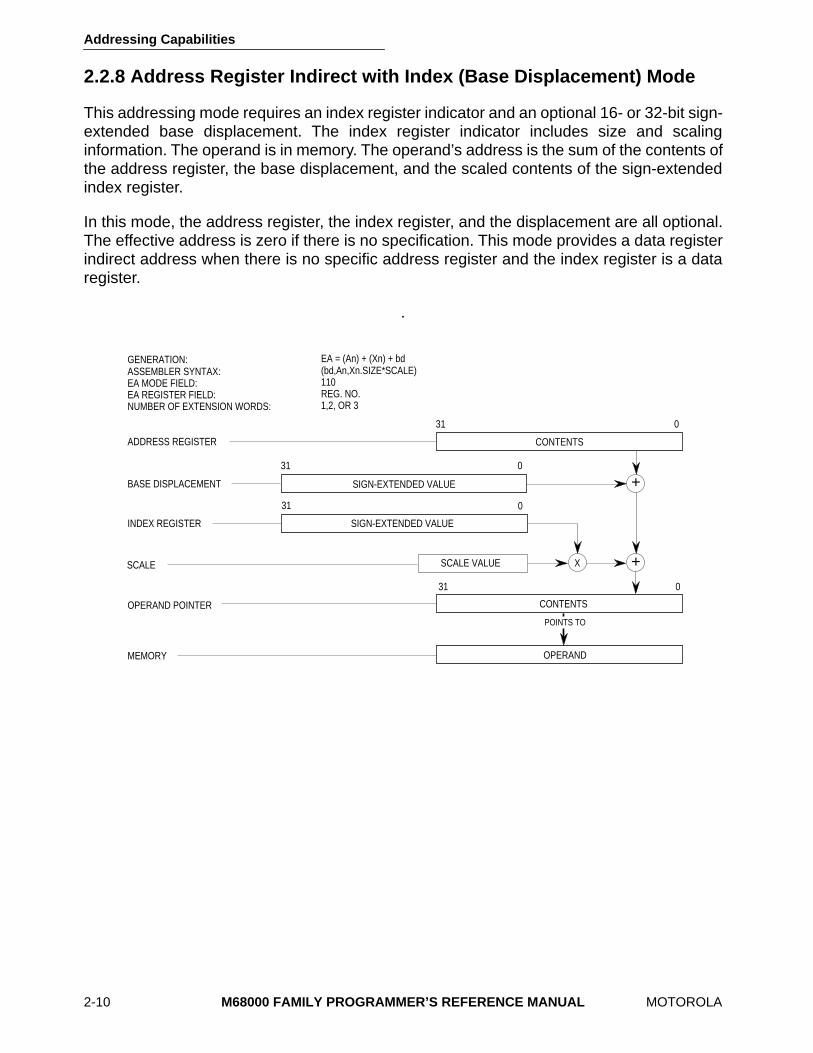
2.2.8 Address Register Indirect with Index (Base Displacement) Mode
This addressing mode requires an index register indicator and an optional 16- or 32-bit sign-extended base displacement. The index register indicator includes size and scalinginformation. The operand is in memory. The operand’s address is the sum of the contents ofthe address register, the base displacement, and the scaled contents of the sign-extendedindex register.
In this mode, the address register, the index register, and the displacement are all optional.The effective address is zero if there is no specification. This mode provides a data registerindirect address when there is no specific address register and the index register is a dataregister.
.
+
+X
CONTENTS
SIGN-EXTENDED VALUE
SCALE VALUE
CONTENTS
31 0
31 0
31 0
031
SIGN-EXTENDED VALUEBASE DISPLACEMENT
INDEX REGISTER
SCALE
OPERAND POINTER
EA = (An) + (Xn) + bd(bd,An,Xn.SIZE*SCALE)110REG. NO.1,2, OR 3
GENERATION:ASSEMBLER SYNTAX:EA MODE FIELD:EA REGISTER FIELD:NUMBER OF EXTENSION WORDS:
ADDRESS REGISTER
MEMORY OPERAND
POINTS TO
Addressing Capabilities
MOTOROLA
M68000 FAMILY PROGRAMMER’S REFERENCE MANUAL
2-11
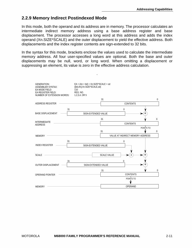
2.2.9 Memory Indirect Postindexed Mode
In this mode, both the operand and its address are in memory. The processor calculates anintermediate indirect memory address using a base address register and basedisplacement. The processor accesses a long word at this address and adds the indexoperand (Xn.SIZE*SCALE) and the outer displacement to yield the effective address. Bothdisplacements and the index register contents are sign-extended to 32 bits.
In the syntax for this mode, brackets enclose the values used to calculate the intermediatememory address. All four user-specified values are optional. Both the base and outerdisplacements may be null, word, or long word. When omitting a displacement orsuppressing an element, its value is zero in the effective address calculation.
.
EA = (An + bd) + Xn.SIZE*SCALE + od([bd,An],Xn.SIZE*SCALE,od)110REG. NO.1,2,3,4, OR 5
+
+X
CONTENTS
SIGN-EXTENDED VALUE
CONTENTS
31 0
31 0
31 0
031
SIGN-EXTENDED VALUE
SCALE VALUE
BASE DISPLACEMENT
INDEX REGISTER
SCALE
OPERAND POINTER
CONTENTS
VALUE AT INDIRECT MEMORY ADDRESS
31 0
31 0
SIGN-EXTENDED VALUE
31 0
+OUTER DISPLACEMENT
GENERATION:ASSEMBLER SYNTAX:EA MODE FIELD:EA REGISTER FIELD:NUMBER OF EXTENSION WORDS:
ADDRESS REGISTER
INTERMEDIATEADDRESS
MEMORY OPERAND
POINTS TO
MEMORY
POINTS TO
Addressing Capabilities
2-12
M68000 FAMILY PROGRAMMER’S REFERENCE MANUAL
MOTOROLA
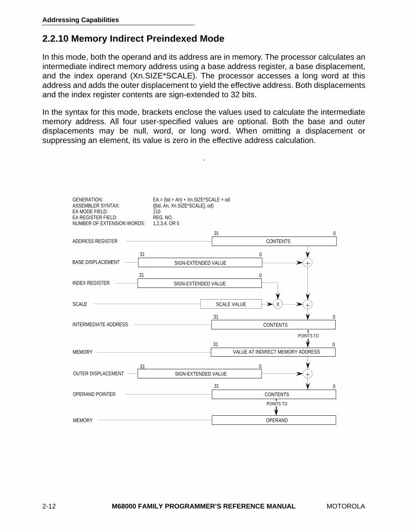
2.2.10 Memory Indirect Preindexed Mode
In this mode, both the operand and its address are in memory. The processor calculates anintermediate indirect memory address using a base address register, a base displacement,and the index operand (Xn.SIZE*SCALE). The processor accesses a long word at thisaddress and adds the outer displacement to yield the effective address. Both displacementsand the index register contents are sign-extended to 32 bits.
In the syntax for this mode, brackets enclose the values used to calculate the intermediatememory address. All four user-specified values are optional. Both the base and outerdisplacements may be null, word, or long word. When omitting a displacement orsuppressing an element, its value is zero in the effective address calculation.
.
EA = (bd + An) + Xn.SIZE*SCALE + od([bd, An, Xn.SIZE*SCALE], od)110REG. NO.1,2,3,4, OR 5
+
+X
CONTENTS
SIGN-EXTENDED VALUE
SCALE VALUE
CONTENTS
31 0
31 0
31 0
031
SIGN-EXTENDED VALUE
SCALE VALUE
GENERATION:ASSEMBLER SYNTAX:EA MODE FIELD:EA REGISTER FIELD:NUMBER OF EXTENSION WORDS:
ADDRESS REGISTER
BASE DISPLACEMENT
INDEX REGISTER
SCALE
OPERAND POINTER
CONTENTS
VALUE AT INDIRECT MEMORY ADDRESS
31 0
31 0
SIGN-EXTENDED VALUE31 0
+OUTER DISPLACEMENT
INTERMEDIATE ADDRESS
MEMORY OPERAND
POINTS TO
POINTS TO
MEMORY
Addressing Capabilities
MOTOROLA
M68000 FAMILY PROGRAMMER’S REFERENCE MANUAL
2-13
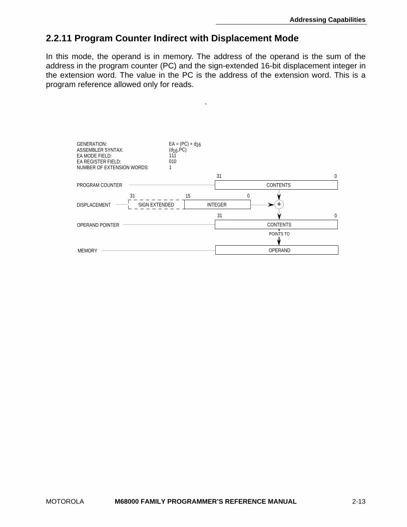
2.2.11 Program Counter Indirect with Displacement Mode
In this mode, the operand is in memory. The address of the operand is the sum of theaddress in the program counter (PC) and the sign-extended 16-bit displacement integer inthe extension word. The value in the PC is the address of the extension word. This is aprogram reference allowed only for reads.
.
+DISPLACEMENT
OPERAND POINTER
CONTENTS
CONTENTS
0
0
31
31
SIGN EXTENDED
31 0
INTEGER
15
EA = (PC) + d(d ,PC)1110101
GENERATION:ASSEMBLER SYNTAX:EA MODE FIELD:EA REGISTER FIELD:NUMBER OF EXTENSION WORDS:
PROGRAM COUNTER
1616
MEMORY OPERAND
POINTS TO
Addressing Capabilities
2-14
M68000 FAMILY PROGRAMMER’S REFERENCE MANUAL
MOTOROLA
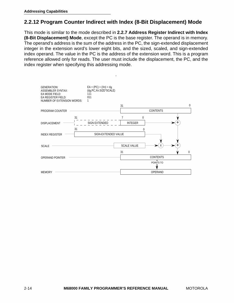
2.2.12 Program Counter Indirect with Index (8-Bit Displacement) Mode
This mode is similar to the mode described in
2.2.7 Address Register Indirect with Index(8-Bit Displacement) Mode
, except the PC is the base register. The operand is in memory.The operand’s address is the sum of the address in the PC, the sign-extended displacementinteger in the extension word’s lower eight bits, and the sized, scaled, and sign-extendedindex operand. The value in the PC is the address of the extension word. This is a programreference allowed only for reads. The user must include the displacement, the PC, and theindex register when specifying this addressing mode.
.
+
+X
SIGN-EXTENDED VALUE
SCALE VALUE
CONTENTS
31 0
31 0
31 0
EA = (PC) + (Xn) + d(d ,PC,Xn.SIZE*SCALE)1110111
DISPLACEMENT
SCALE
OPERAND POINTER
INDEX REGISTER
INTEGERSIGN EXTENDED
031 7
88
CONTENTS
GENERATION:ASSEMBLER SYNTAX:EA MODE FIELD:EA REGISTER FIELD:NUMBER OF EXTENSION WORDS:
PROGRAM COUNTER
MEMORY OPERAND
POINTS TO
Addressing Capabilities
MOTOROLA
M68000 FAMILY PROGRAMMER’S REFERENCE MANUAL
2-15
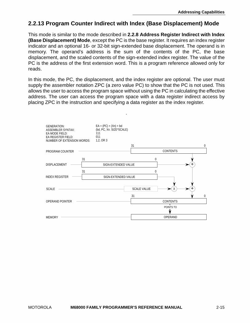
2.2.13 Program Counter Indirect with Index (Base Displacement) Mode
This mode is similar to the mode described in
2.2.8 Address Register Indirect with Index(Base Displacement) Mode
, except the PC is the base register. It requires an index registerindicator and an optional 16- or 32-bit sign-extended base displacement. The operand is inmemory. The operand’s address is the sum of the contents of the PC, the basedisplacement, and the scaled contents of the sign-extended index register. The value of thePC is the address of the first extension word. This is a program reference allowed only forreads.
In this mode, the PC, the displacement, and the index register are optional. The user mustsupply the assembler notation ZPC (a zero value PC) to show that the PC is not used. Thisallows the user to access the program space without using the PC in calculating the effectiveaddress. The user can access the program space with a data register indirect access byplacing ZPC in the instruction and specifying a data register as the index register.
.
+
+X
CONTENTS
SIGN-EXTENDED VALUE
SCALE VALUE
CONTENTS
31 0
31 0
31 0
EA = (PC) + (Xn) + bd(bd, PC, Xn. SIZE*SCALE)1110111,2, OR 3
031
SIGN-EXTENDED VALUEDISPLACEMENT
SCALE
OPERAND POINTER
INDEX REGISTER
GENERATION:ASSEMBLER SYNTAX:EA MODE FIELD:EA REGISTER FIELD:NUMBER OF EXTENSION WORDS:
PROGRAM COUNTER
MEMORY OPERAND
POINTS TO
Addressing Capabilities
2-16
M68000 FAMILY PROGRAMMER’S REFERENCE MANUAL
MOTOROLA
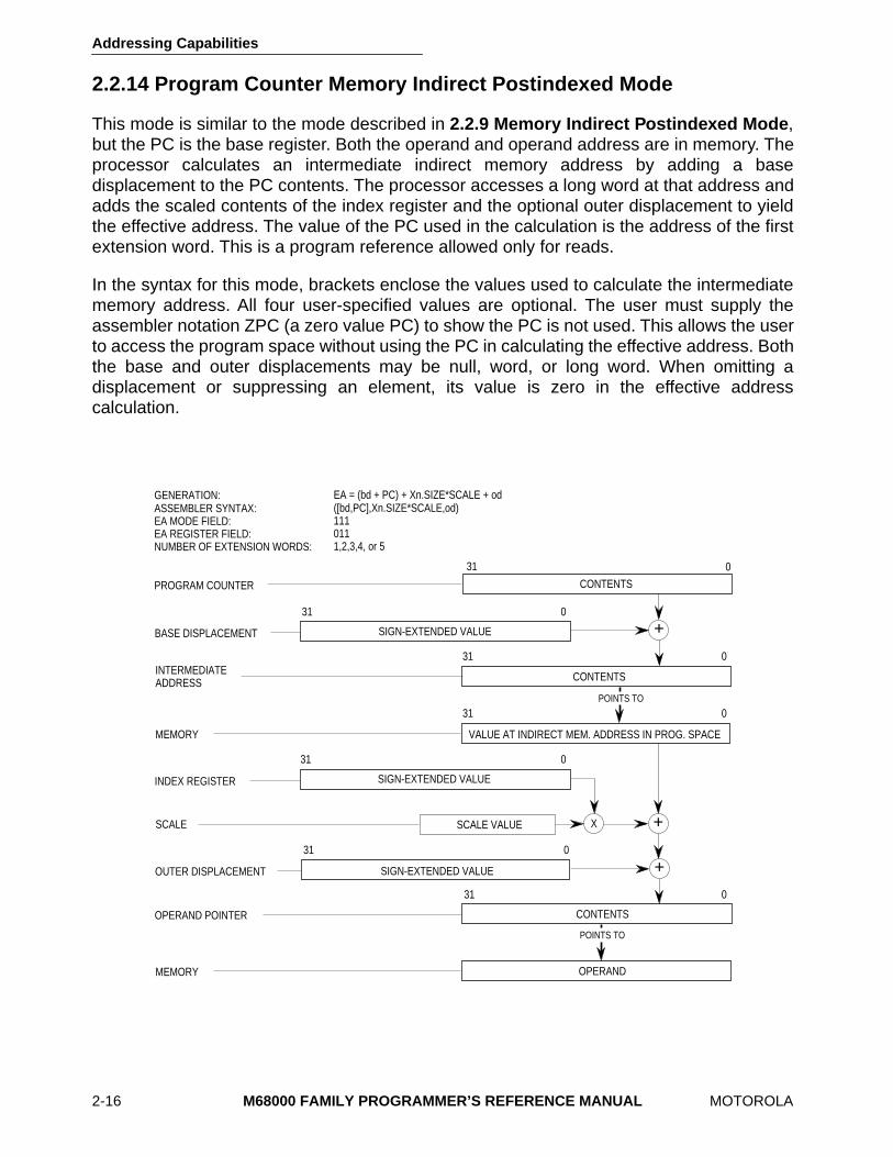
2.2.14 Program Counter Memory Indirect Postindexed Mode
This mode is similar to the mode described in
2.2.9 Memory Indirect Postindexed Mode
,but the PC is the base register. Both the operand and operand address are in memory. Theprocessor calculates an intermediate indirect memory address by adding a basedisplacement to the PC contents. The processor accesses a long word at that address andadds the scaled contents of the index register and the optional outer displacement to yieldthe effective address. The value of the PC used in the calculation is the address of the firstextension word. This is a program reference allowed only for reads.
In the syntax for this mode, brackets enclose the values used to calculate the intermediatememory address. All four user-specified values are optional. The user must supply theassembler notation ZPC (a zero value PC) to show the PC is not used. This allows the userto access the program space without using the PC in calculating the effective address. Boththe base and outer displacements may be null, word, or long word. When omitting adisplacement or suppressing an element, its value is zero in the effective addresscalculation.
EA = (bd + PC) + Xn.SIZE*SCALE + od([bd,PC],Xn.SIZE*SCALE,od)1110111,2,3,4, or 5
+
+X
SIGN-EXTENDED VALUE
SCALE VALUE
CONTENTS
31 0
31 0
031
SIGN-EXTENDED VALUE
CONTENTS
VALUE AT INDIRECT MEM. ADDRESS IN PROG. SPACE
31 0
31 0
SIGN-EXTENDED VALUE
31 0
+
BASE DISPLACEMENT
INDEX REGISTER
SCALE
OPERAND POINTER
OUTER DISPLACEMENT
GENERATION:ASSEMBLER SYNTAX:EA MODE FIELD:EA REGISTER FIELD:NUMBER OF EXTENSION WORDS:
PROGRAM COUNTER
INTERMEDIATEADDRESS
CONTENTS
31 0
MEMORY OPERAND
POINTS TO
POINTS TO
MEMORY
Addressing Capabilities
MOTOROLA
M68000 FAMILY PROGRAMMER’S REFERENCE MANUAL
2-17
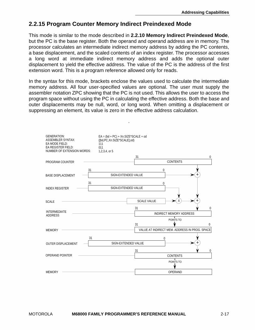
2.2.15 Program Counter Memory Indirect Preindexed Mode
This mode is similar to the mode described in
2.2.10 Memory Indirect Preindexed Mode
,but the PC is the base register. Both the operand and operand address are in memory. Theprocessor calculates an intermediate indirect memory address by adding the PC contents,a base displacement, and the scaled contents of an index register. The processor accessesa long word at immediate indirect memory address and adds the optional outerdisplacement to yield the effective address. The value of the PC is the address of the firstextension word. This is a program reference allowed only for reads.
In the syntax for this mode, brackets enclose the values used to calculate the intermediatememory address. All four user-specified values are optional. The user must supply theassembler notation ZPC showing that the PC is not used. This allows the user to access theprogram space without using the PC in calculating the effective address. Both the base andouter displacements may be null, word, or long word. When omitting a displacement orsuppressing an element, its value is zero in the effective address calculation.
.
+
+X
SIGN-EXTENDED VALUE
SCALE VALUE
31 0
31 0
031
SIGN-EXTENDED VALUE
INDIRECT MEMORY ADDRESS
VALUE AT INDIRECT MEM. ADDRESS IN PROG. SPACE
31 0
31 0
SIGN-EXTENDED VALUE
31 0+
BASE DISPLACEMENT
INDEX REGISTER
SCALE
OPERAND POINTER
OUTER DISPLACEMENT
GENERATION:ASSEMBLER SYNTAX:EA MODE FIELD:EA REGISTER FIELD:NUMBER OF EXTENSION WORDS:
PROGRAM COUNTER
INTERMEDIATEADDRESS
EA = (bd + PC) + Xn.SIZE*SCALE + od([bd,PC,Xn.SIZE*SCALE],od)1110111,2,3,4, or 5
CONTENTS
CONTENTS
31 0
MEMORY OPERAND
POINTS TO
POINTS TO
MEMORY
Addressing Capabilities
2-18
M68000 FAMILY PROGRAMMER’S REFERENCE MANUAL
MOTOROLA
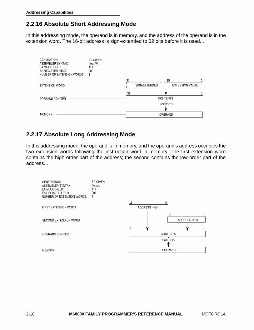
2.2.16 Absolute Short Addressing Mode
In this addressing mode, the operand is in memory, and the address of the operand is in theextension word. The 16-bit address is sign-extended to 32 bits before it is used. .
2.2.17 Absolute Long Addressing Mode
In this addressing mode, the operand is in memory, and the operand’s address occupies thetwo extension words following the instruction word in memory. The first extension wordcontains the high-order part of the address; the second contains the low-order part of theaddress. .
31
31 15 0
0
EA GIVEN(xxx).W1110001
CONTENTS
SIGN-EXTENDED EXTENSION VALUE
OPERAND POINTER
GENERATION:ASSEMBLER SYNTAX:EA MODE FIELD:EA REGISTER FIELD:NUMBER OF EXTENSION WORDS:
EXTENSION WORD
MEMORY OPERAND
POINTS TO
15 0
15 0
SECOND EXTENSION WORD
ADDRESS HIGH
ADDRESS LOW
EA GIVEN(xxx).L1110012
GENERATION:ASSEMBLER SYNTAX:EA MODE FIELD:EA REGISTER FIELD:NUMBER OF EXTENSION WORDS:
FIRST EXTENSION WORD
0
CONTENTSOPERAND POINTER
MEMORY OPERAND
POINTS TO
31
Addressing Capabilities
MOTOROLA
M68000 FAMILY PROGRAMMER’S REFERENCE MANUAL
2-19
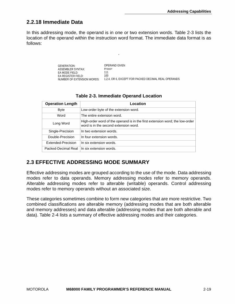
2.2.18 Immediate Data
In this addressing mode, the operand is in one or two extension words. Table 2-3 lists thelocation of the operand within the instruction word format. The immediate data format is asfollows:
.
2.3 EFFECTIVE ADDRESSING MODE SUMMARY
Effective addressing modes are grouped according to the use of the mode. Data addressingmodes refer to data operands. Memory addressing modes refer to memory operands.Alterable addressing modes refer to alterable (writable) operands. Control addressingmodes refer to memory operands without an associated size.
These categories sometimes combine to form new categories that are more restrictive. Twocombined classifications are alterable memory (addressing modes that are both alterableand memory addresses) and data alterable (addressing modes that are both alterable anddata). Table 2-4 lists a summary of effective addressing modes and their categories.
Table 2-3. Immediate Operand Location
Operation Length Location
Byte Low-order byte of the extension word.
Word The entire extension word.
Long WordHigh-order word of the operand is in the first extension word; the low-order word is in the second extension word.
Single-Precision In two extension words.
Double-Precision In four extension words.
Extended-Precision In six extension words.
Packed-Decimal Real In six extension words.
OPERAND GIVEN#<xxx>1111001,2,4, OR 6, EXCEPT FOR PACKED DECIMAL REAL OPERANDS
GENERATION:ASSEMBLER SYNTAX:EA MODE FIELD:EA REGISTER FIELD:NUMBER OF EXTENSION WORDS:

Addressing Capabilities
2-20
M68000 FAMILY PROGRAMMER’S REFERENCE MANUAL
MOTOROLA
Table 2-4. Effective Addressing Modes and Categories
Addressing Modes SyntaxModeField
Reg.Field Data Memory Control Alterable
Register Direct Data Address
DnAn
000001
reg. no.reg. no.
X—
——
——
XX
Register IndirectAddressAddress with PostincrementAddress with PredecrementAddress with Displacement
(An)(An)+–(An)
(d
16
,An)
010011100101
reg. no.reg. no.reg. no.reg. no.
XXXX
XXXX
X——X
XXXX
Address Register Indirect with Index8-Bit DisplacementBase Displacement
(d
8
,An,Xn)(bd,An,Xn)
110110
reg. no.reg. no.
XX
XX
XX
XX
Memory IndirectPostindexedPreindexed
([bd,An],Xn,od)([bd,An,Xn],od)
110110
reg. no.reg. no.
XX
XX
XX
XX
Program Counter Indirectwith Displacement (d
16
,PC) 111 010 X X X —
Program Counter Indirect with Index 8-Bit DisplacementBase Displacement
(d
8
,PC,Xn)(bd,PC,Xn)
111111
011011
XX
XX
XX
——
Program Counter Memory IndirectPostindexedPreindexed
([bd,PC],Xn,od)([bd,PC,Xn],od)
111111
011011
XX
XX
XX
XX
Absolute Data Addressing ShortLong
(xxx).W(xxx).L
111111
000000
XX
XX
XX
——
Immediate #<xxx> 111 100 X X — —
Addressing Capabilities
2-28 M68000 FAMILY PROGRAMMER’S REFERENCE MANUAL MOTOROLA
2.6 OTHER DATA STRUCTURES
Stacks and queues are common data structures. The M68000 family implements a systemstack and instructions that support user stacks and queues.
2.6.1 System Stack
Address register seven (A7) is the system stack pointer. Either the user stack pointer (USP),the interrupt stack pointer (ISP), or the master stack pointer (MSP) is active at any one time.Refer to Section 1 Introduction for details on these stack pointers. To keep data on thesystem stack aligned for maximum efficiency, the active stack pointer is automaticallydecremented or incremented by two for all byte-size operands moved to or from the stack.In long-word-organized memory, aligning the stack pointer on a long-word addresssignificantly increases the efficiency of stacking exception frames, subroutine calls andreturns, and other stacking operations.
The user can implement stacks with the address register indirect with postincrement andpredecrement addressing modes. With an address register the user can implement a stackthat fills either from high memory to low memory or from low memory to high memory.Important consideration are:
• Use the predecrement mode to decrement the register before using its contents as the pointer to the stack.
• Use the postincrement mode to increment the register after using its contents as the pointer to the stack.
• Maintain the stack pointer correctly when byte, word, and long-word items mix in these stacks.
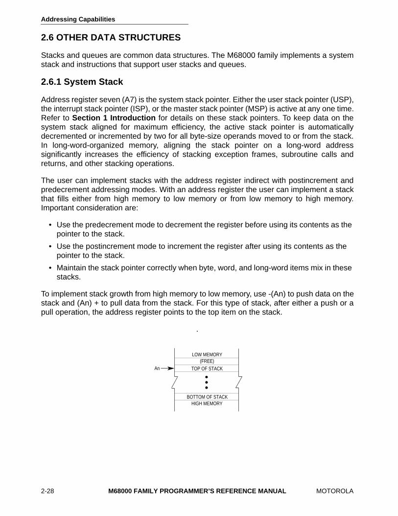
To implement stack growth from high memory to low memory, use -(An) to push data on thestack and (An) + to pull data from the stack. For this type of stack, after either a push or apull operation, the address register points to the top item on the stack.
.
BOTTOM OF STACK
LOW MEMORY(FREE)
TOP OF STACK
HIGH MEMORY
An
Addressing Capabilities
MOTOROLA M68000 FAMILY PROGRAMMER’S REFERENCE MANUAL 2-29
To implement stack growth from low memory to high memory, use (An) + to push data onthe stack and -(An) to pull data from the stack. After either a push or pull operation, theaddress register points to the next available space on the stack. .
2.6.2 Queues
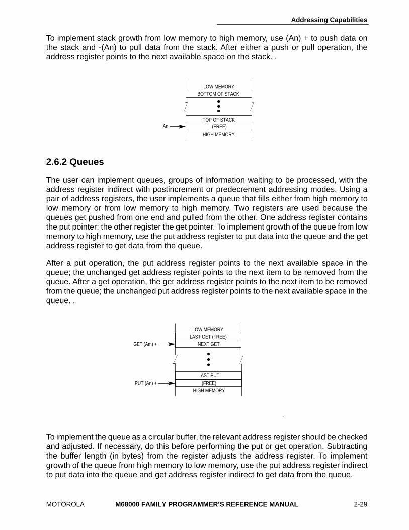
The user can implement queues, groups of information waiting to be processed, with theaddress register indirect with postincrement or predecrement addressing modes. Using apair of address registers, the user implements a queue that fills either from high memory tolow memory or from low memory to high memory. Two registers are used because thequeues get pushed from one end and pulled from the other. One address register containsthe put pointer; the other register the get pointer. To implement growth of the queue from lowmemory to high memory, use the put address register to put data into the queue and the getaddress register to get data from the queue.
After a put operation, the put address register points to the next available space in thequeue; the unchanged get address register points to the next item to be removed from thequeue. After a get operation, the get address register points to the next item to be removedfrom the queue; the unchanged put address register points to the next available space in thequeue. .
To implement the queue as a circular buffer, the relevant address register should be checkedand adjusted. If necessary, do this before performing the put or get operation. Subtractingthe buffer length (in bytes) from the register adjusts the address register. To implementgrowth of the queue from high memory to low memory, use the put address register indirectto put data into the queue and get address register indirect to get data from the queue.
BOTTOM OF STACKLOW MEMORY
TOP OF STACK(FREE)
HIGH MEMORY
An
GET (Am) +
PUT (An) +HIGH MEMORY
LOW MEMORY
(FREE)
LAST GET (FREE)NEXT GET
LAST PUT
Addressing Capabilities
2-30 M68000 FAMILY PROGRAMMER’S REFERENCE MANUAL MOTOROLA
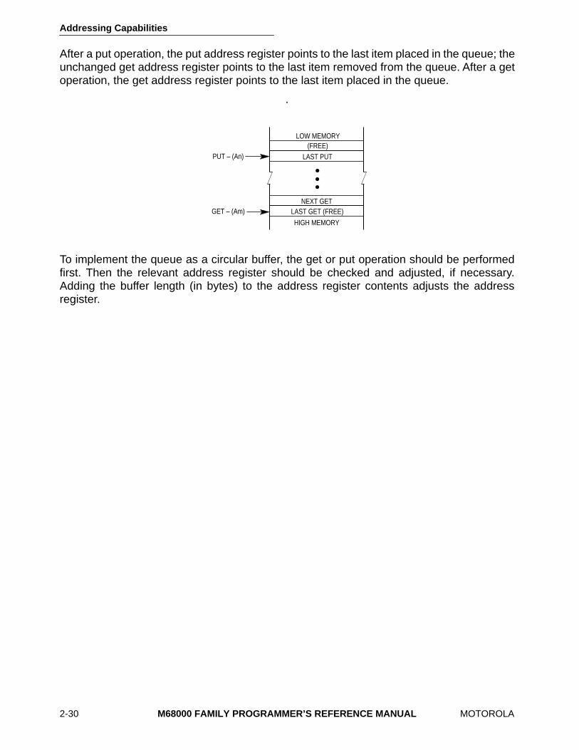
After a put operation, the put address register points to the last item placed in the queue; theunchanged get address register points to the last item removed from the queue. After a getoperation, the get address register points to the last item placed in the queue.
.
To implement the queue as a circular buffer, the get or put operation should be performedfirst. Then the relevant address register should be checked and adjusted, if necessary.Adding the buffer length (in bytes) to the address register contents adjusts the addressregister.
GET – (Am)
PUT – (An)
HIGH MEMORY
LOW MEMORY
LAST PUT(FREE)
NEXT GETLAST GET (FREE)
MOTOROLA
M68000 FAMILY PROGRAMMER’S REFERENCE MANUAL
3-1
SECTION 3INSTRUCTION SET SUMMARY
This section briefly describes the M68000 family instruction set, using Motorola,s assemblylanguage syntax and notation. It includes instruction set details such as notation and format,selected instruction examples, and an integer condition code discussion. The sectionconcludes with a discussion of floating-point details such as computational accuracy,conditional test definitions, an explanation of the operation table, and a discussion of not-a-numbers (NANs) and postprocessing.
3.1 INSTRUCTION SUMMARY
Instructions form a set of tools that perform the following types of operations:
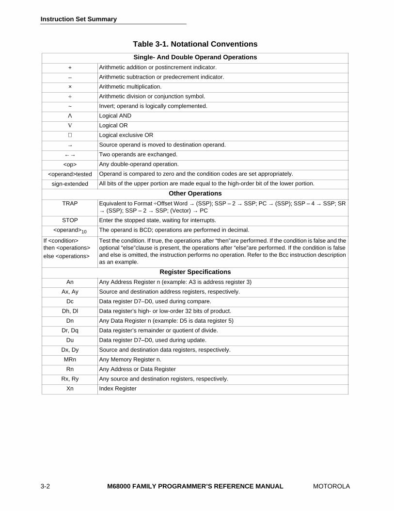
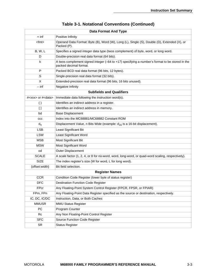
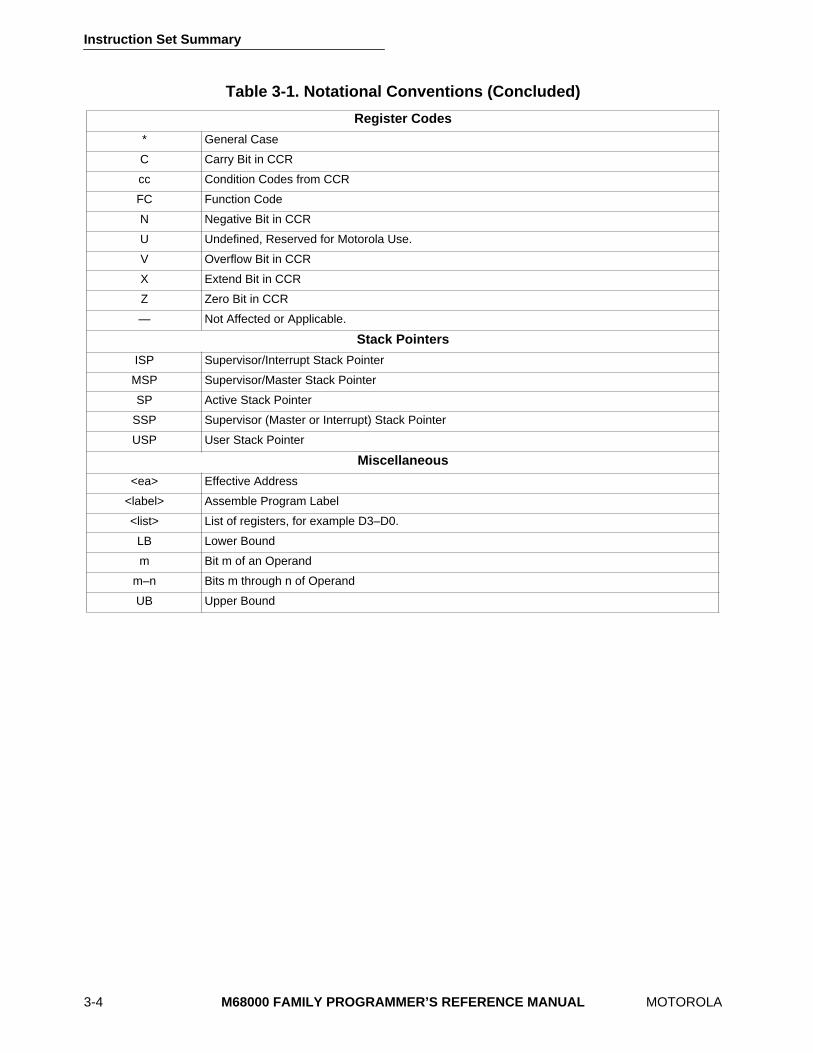
The following paragraphs describe in detail the instruction for each type of operation. Table3-1 lists the notations used throughout this manual. In the operand syntax statements of theinstruction definitions, the operand on the right is the destination operand.
Data Movement Program Control
Integer Arithmetic System Control
Logical Operations Cache Maintenance
Shift and Rotate Operations Multiprocessor Communications
Bit Manipulation Memory Management
Bit Field Manipulation Floating-Point Arithmetic
Binary-Coded Decimal Arithmetic
Instruction Set Summary
3-2
M68000 FAMILY PROGRAMMER’S REFERENCE MANUAL
MOTOROLA
Table 3-1. Notational Conventions
Single- And Double Operand Operations
+ Arithmetic addition or postincrement indicator.
– Arithmetic subtraction or predecrement indicator.
×
Arithmetic multiplication.
÷
Arithmetic division or conjunction symbol.
~ Invert; operand is logically complemented.
Λ
Logical AND
V
Logical OR
⊕
Logical exclusive OR
→
Source operand is moved to destination operand.
←→
Two operands are exchanged.
<op> Any double-operand operation.
<operand>tested Operand is compared to zero and the condition codes are set appropriately.
sign-extended All bits of the upper portion are made equal to the high-order bit of the lower portion.
Other Operations
TRAP Equivalent to Format
÷
Offset Word
→
(SSP); SSP – 2
→
SSP; PC
→
(SSP); SSP – 4
→
SSP; SR
→
(SSP); SSP – 2
→
SSP; (Vector)
→
PC
STOP Enter the stopped state, waiting for interrupts.
<operand>
10
The operand is BCD; operations are performed in decimal.
If <condition>then <operations>else <operations>
Test the condition. If true, the operations after “then”are performed. If the condition is false and the optional “else”clause is present, the operations after “else”are performed. If the condition is false and else is omitted, the instruction performs no operation. Refer to the Bcc instruction description as an example.
Register Specifications
An Any Address Register n (example: A3 is address register 3)
Ax, Ay Source and destination address registers, respectively.
Dc Data register D7–D0, used during compare.
Dh, Dl Data register’s high- or low-order 32 bits of product.
Dn Any Data Register n (example: D5 is data register 5)
Dr, Dq Data register’s remainder or quotient of divide.
Du Data register D7–D0, used during update.
Dx, Dy Source and destination data registers, respectively.
MRn Any Memory Register n.
Rn Any Address or Data Register
Rx, Ry Any source and destination registers, respectively.
Xn Index Register
Instruction Set Summary
MOTOROLA
M68000 FAMILY PROGRAMMER’S REFERENCE MANUAL
3-3
Table 3-1. Notational Conventions (Continued)
Data Format And Type
+ inf Positive Infinity
<fmt> Operand Data Format: Byte (B), Word (W), Long (L), Single (S), Double (D), Extended (X), or Packed (P).
B, W, L Specifies a signed integer data type (twos complement) of byte, word, or long word.
D Double-precision real data format (64 bits).
k A twos complement signed integer (–64 to +17) specifying a number’s format to be stored in the packed decimal format.
P Packed BCD real data format (96 bits, 12 bytes).
S Single-precision real data format (32 bits).
X Extended-precision real data format (96 bits, 16 bits unused).
– inf Negative Infinity
Subfields and Qualifiers
#<xxx> or #<data> Immediate data following the instruction word(s).
( ) Identifies an indirect address in a register.
[ ] Identifies an indirect address in memory.
bd Base Displacement
ccc Index into the MC68881/MC68882 Constant ROM
d
n
Displacement Value, n Bits Wide (example: d
16
is a 16-bit displacement).
LSB Least Significant Bit
LSW Least Significant Word
MSB Most Significant Bit
MSW Most Significant Word
od Outer Displacement
SCALE A scale factor (1, 2, 4, or 8 for no-word, word, long-word, or quad-word scaling, respectively).
SIZE The index register’s size (W for word, L for long word).
{offset:width} Bit field selection.
Register Names
CCR Condition Code Register (lower byte of status register)
DFC Destination Function Code Register
FPcr Any Floating-Point System Control Register (FPCR, FPSR, or FPIAR)
FPm, FPn Any Floating-Point Data Register specified as the source or destination, respectively.
IC, DC, IC/DC Instruction, Data, or Both Caches
MMUSR MMU Status Register
PC Program Counter
Rc Any Non Floating-Point Control Register
SFC Source Function Code Register
SR Status Register
Instruction Set Summary
3-4
M68000 FAMILY PROGRAMMER’S REFERENCE MANUAL
MOTOROLA
Table 3-1. Notational Conventions (Concluded)
Register Codes
* General Case
C Carry Bit in CCR
cc Condition Codes from CCR
FC Function Code
N Negative Bit in CCR
U Undefined, Reserved for Motorola Use.
V Overflow Bit in CCR
X Extend Bit in CCR
Z Zero Bit in CCR
— Not Affected or Applicable.
Stack Pointers
ISP Supervisor/Interrupt Stack Pointer
MSP Supervisor/Master Stack Pointer
SP Active Stack Pointer
SSP Supervisor (Master or Interrupt) Stack Pointer
USP User Stack Pointer
Miscellaneous
<ea> Effective Address
<label> Assemble Program Label
<list> List of registers, for example D3–D0.
LB Lower Bound
m Bit m of an Operand
m–n Bits m through n of Operand
UB Upper Bound
Instruction Set Summary
MOTOROLA
M68000 FAMILY PROGRAMMER’S REFERENCE MANUAL
3-5
3.1.1 Data Movement Instructions
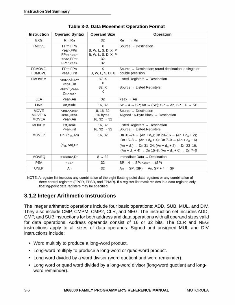
The MOVE and FMOVE instructions with their associated addressing modes are the basicmeans of transferring and storing addresses and data. MOVE instructions transfer byte,word, and long-word operands from memory to memory, memory to register, register tomemory, and register to register. MOVE instructions transfer word and long-word operandsand ensure that only valid address manipulations are executed. In addition to the generalMOVE instructions, there are several special data movement instructions: MOVE16,MOVEM, MOVEP, MOVEQ, EXG, LEA, PEA, LINK, and UNLK. The MOVE16 instruction isan MC68040 extension to the M68000 instruction set.
The FMOVE instructions move operands into, out of, and between floating-point dataregisters. FMOVE also moves operands to and from the floating-point control register(FPCR), floating-point status register (FPSR), and floating-point instruction address register(FPIAR). For operands moved into a floating-point data register, FSMOVE and FDMOVEexplicitly select single- and double-precision rounding of the result, respectively. FMOVEMmoves any combination of either floating-point data registers or floating-point controlregisters. Table 3-2 lists the general format of these integer and floating-point datamovement instructions.
Instruction Set Summary
3-6
M68000 FAMILY PROGRAMMER’S REFERENCE MANUAL
MOTOROLA
NOTE: A register list includes any combination of the eight floating-point data registers or any combination ofthree control registers (FPCR, FPSR, and FPIAR). If a register list mask resides in a data register, onlyfloating-point data registers may be specified.
3.1.2 Integer Arithmetic Instructions
The integer arithmetic operations include four basic operations: ADD, SUB, MUL, and DIV.They also include CMP, CMPM, CMP2, CLR, and NEG. The instruction set includes ADD,CMP, and SUB instructions for both address and data operations with all operand sizes validfor data operations. Address operands consist of 16 or 32 bits. The CLR and NEGinstructions apply to all sizes of data operands. Signed and unsigned MUL and DIVinstructions include:
• Word multiply to produce a long-word product.
• Long-word multiply to produce a long-word or quad-word product.
• Long word divided by a word divisor (word quotient and word remainder).
• Long word or quad word divided by a long-word divisor (long-word quotient and long-word remainder).
Table 3-2. Data Movement Operation Format
Instruction Operand Syntax Operand Size Operation
EXG Rn, Rn 32 Rn
←
→
Rn
FMOVE FPm,FPn<ea>,FPnFPm,<ea><ea>,FPcrFPcr,<ea>
XB, W, L, S, D, X, PB, W, L, S, D, X, P
3232
Source
→
Destination
FSMOVE,FDMOVE
FPm,FPn<ea>,FPn
XB, W, L, S, D, X
Source
→
Destination; round destination to single or double precision.
FMOVEM <ea>,<list>
1
<ea>,Dn
<list>
1
,<ea>Dn,<ea>
32, XX
32, XX
Listed Registers
→
Destination
Source
→
Listed Registers
LEA <ea>,An 32 <ea>
→
An
LINK An,#<d> 16, 32 SP – 4
→
SP; An
→
(SP); SP
→
An, SP + D
→
SP
MOVEMOVE16MOVEA
<ea>,<ea><ea>,<ea><ea>,An
8, 16, 3216 bytes
16, 32
→
32
Source
→
DestinationAligned 16-Byte Block
→
Destination
MOVEM list,<ea><ea>,list
16, 3216, 32
→
32Listed Registers
→
DestinationSource
→
Listed Registers
MOVEP Dn, (d
16
,An)
(d
16
,An),Dn
16, 32 Dn 31–24
→
(An + d
n
); Dn 23–16
→
(An + d
n
+ 2); Dn 15–8
→
(An + d
n
+ 4); Dn 7–0
→
(An + d
n
+ 6)
(An + d
n
)
→
Dn 31–24; (An + d
n
+ 2)
→
Dn 23–16; (An + d
n
+ 4)
→
Dn 15–8; (An + d
n
+ 6)
→
Dn 7–0
MOVEQ #<data>,Dn 8
→
32 Immediate Data
→
Destination
PEA <ea> 32 SP – 4
→
SP; <ea>
→
(SP)
UNLK An 32 An
→
SP; (SP)
→
An; SP + 4
→
SP
Instruction Set Summary
MOTOROLA
M68000 FAMILY PROGRAMMER’S REFERENCE MANUAL
3-7
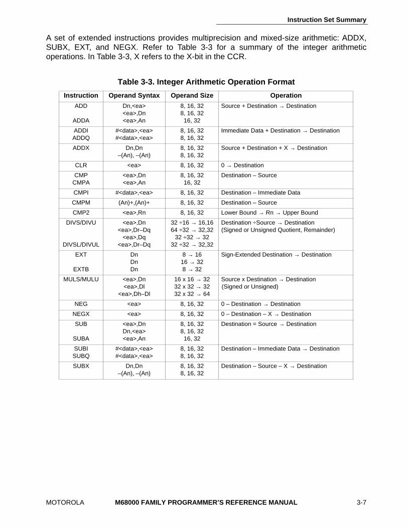
A set of extended instructions provides multiprecision and mixed-size arithmetic: ADDX,SUBX, EXT, and NEGX. Refer to Table 3-3 for a summary of the integer arithmeticoperations. In Table 3-3, X refers to the X-bit in the CCR.
Table 3-3. Integer Arithmetic Operation Format
Instruction Operand Syntax Operand Size Operation
ADD
ADDA
Dn,<ea><ea>,Dn<ea>,An
8, 16, 328, 16, 3216, 32
Source + Destination
→
Destination
ADDIADDQ
#<data>,<ea>#<data>,<ea>
8, 16, 328, 16, 32
Immediate Data + Destination
→
Destination
ADDX Dn,Dn–(An), –(An)
8, 16, 328, 16, 32
Source + Destination + X
→
Destination
CLR <ea> 8, 16, 32 0
→
Destination
CMPCMPA
<ea>,Dn<ea>,An
8, 16, 3216, 32
Destination – Source
CMPI #<data>,<ea> 8, 16, 32 Destination – Immediate Data
CMPM (An)+,(An)+ 8, 16, 32 Destination – Source
CMP2 <ea>,Rn 8, 16, 32 Lower Bound
→
Rn
→
Upper Bound
DIVS/DIVU
DIVSL/DIVUL
<ea>,Dn<ea>,Dr–Dq
<ea>,Dq<ea>,Dr–Dq
32
÷
16
→
16,1664
÷
32
→
32,3232
÷
32
→
3232
÷
32
→
32,32
Destination
÷
Source
→
Destination(Signed or Unsigned Quotient, Remainder)
EXT
EXTB
DnDnDn
8
→
1616
→
328
→
32
Sign-Extended Destination
→
Destination
MULS/MULU <ea>,Dn<ea>,Dl
<ea>,Dh–Dl
16 x 16
→
3232 x 32
→
3232 x 32
→
64
Source x Destination
→
Destination(Signed or Unsigned)
NEG <ea> 8, 16, 32 0 – Destination → Destination
NEGX <ea> 8, 16, 32 0 – Destination – X → Destination
SUB
SUBA
<ea>,DnDn,<ea><ea>,An
8, 16, 328, 16, 3216, 32
Destination = Source → Destination
SUBISUBQ
#<data>,<ea>#<data>,<ea>
8, 16, 328, 16, 32
Destination – Immediate Data → Destination
SUBX Dn,Dn–(An), –(An)
8, 16, 328, 16, 32
Destination – Source – X → Destination
Instruction Set Summary
3-8 M68000 FAMILY PROGRAMMER’S REFERENCE MANUAL MOTOROLA
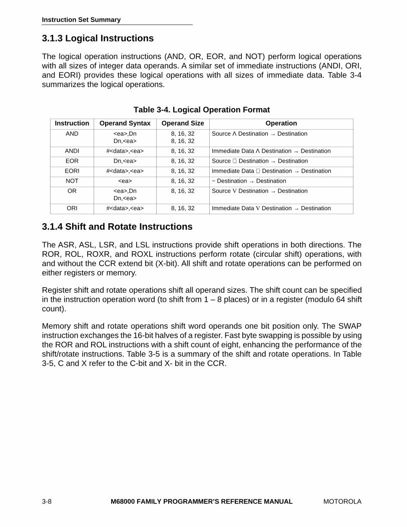
3.1.3 Logical Instructions
The logical operation instructions (AND, OR, EOR, and NOT) perform logical operationswith all sizes of integer data operands. A similar set of immediate instructions (ANDI, ORI,and EORI) provides these logical operations with all sizes of immediate data. Table 3-4summarizes the logical operations.
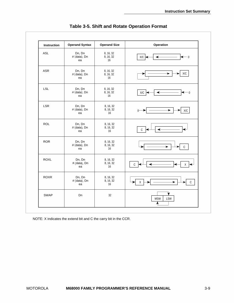
3.1.4 Shift and Rotate Instructions
The ASR, ASL, LSR, and LSL instructions provide shift operations in both directions. TheROR, ROL, ROXR, and ROXL instructions perform rotate (circular shift) operations, withand without the CCR extend bit (X-bit). All shift and rotate operations can be performed oneither registers or memory.
Register shift and rotate operations shift all operand sizes. The shift count can be specifiedin the instruction operation word (to shift from 1 – 8 places) or in a register (modulo 64 shiftcount).
Memory shift and rotate operations shift word operands one bit position only. The SWAPinstruction exchanges the 16-bit halves of a register. Fast byte swapping is possible by usingthe ROR and ROL instructions with a shift count of eight, enhancing the performance of theshift/rotate instructions. Table 3-5 is a summary of the shift and rotate operations. In Table3-5, C and X refer to the C-bit and X- bit in the CCR.
Table 3-4. Logical Operation Format
Instruction Operand Syntax Operand Size Operation
AND <ea>,DnDn,<ea>
8, 16, 328, 16, 32
Source Λ Destination → Destination
ANDI #<data>,<ea> 8, 16, 32 Immediate Data Λ Destination → Destination
EOR Dn,<ea> 8, 16, 32 Source ⊕ Destination → Destination
EORI #<data>,<ea> 8, 16, 32 Immediate Data ⊕ Destination → Destination
NOT <ea> 8, 16, 32 ~ Destination → Destination
OR <ea>,DnDn,<ea>
8, 16, 32 Source V Destination → Destination
ORI #<data>,<ea> 8, 16, 32 Immediate Data V Destination → Destination
Instruction Set Summary
MOTOROLA M68000 FAMILY PROGRAMMER’S REFERENCE MANUAL 3-9
NOTE: X indicates the extend bit and C the carry bit in the CCR.
Table 3-5. Shift and Rotate Operation Format
X/C 0
X/C
X/C 0
X/C0
C
C
XC
X C
MSW LSW
ASL Dn, Dn # data , Dn
ea
8, 16, 32 8, 16, 32
16
Instruction Operand Syntax Operand Size
ASR Dn, Dn # data , Dn
ea
8, 16, 32 8, 16, 32
16
LSL Dn, Dn # data , Dn
ea
8, 16, 32 8, 16, 32
16
LSR Dn, Dn # data , Dn
ea
8, 16, 32 8, 16, 32
16
ROL Dn, Dn # data , Dn
ea
8, 16, 32 8, 16, 32
16
ROR Dn, Dn # data , Dn
ea
8, 16, 32 8, 16, 32
16
ROXL Dn, Dn # data , Dn
ea
8, 16, 32 8, 16, 32
16
ROXR Dn, Dn # data , Dn
ea
8, 16, 32 8, 16, 32
16
SWAP Dn 32
Operation
Instruction Set Summary
MOTOROLA M68000 FAMILY PROGRAMMER’S REFERENCE MANUAL 3-17
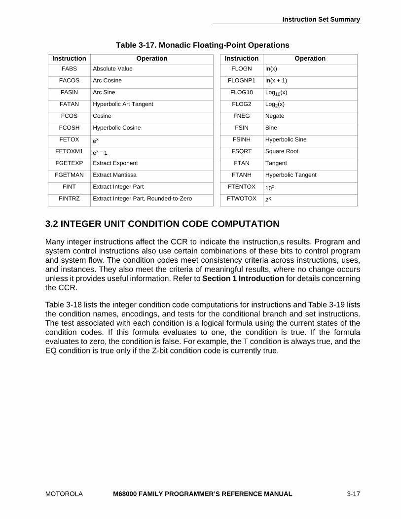
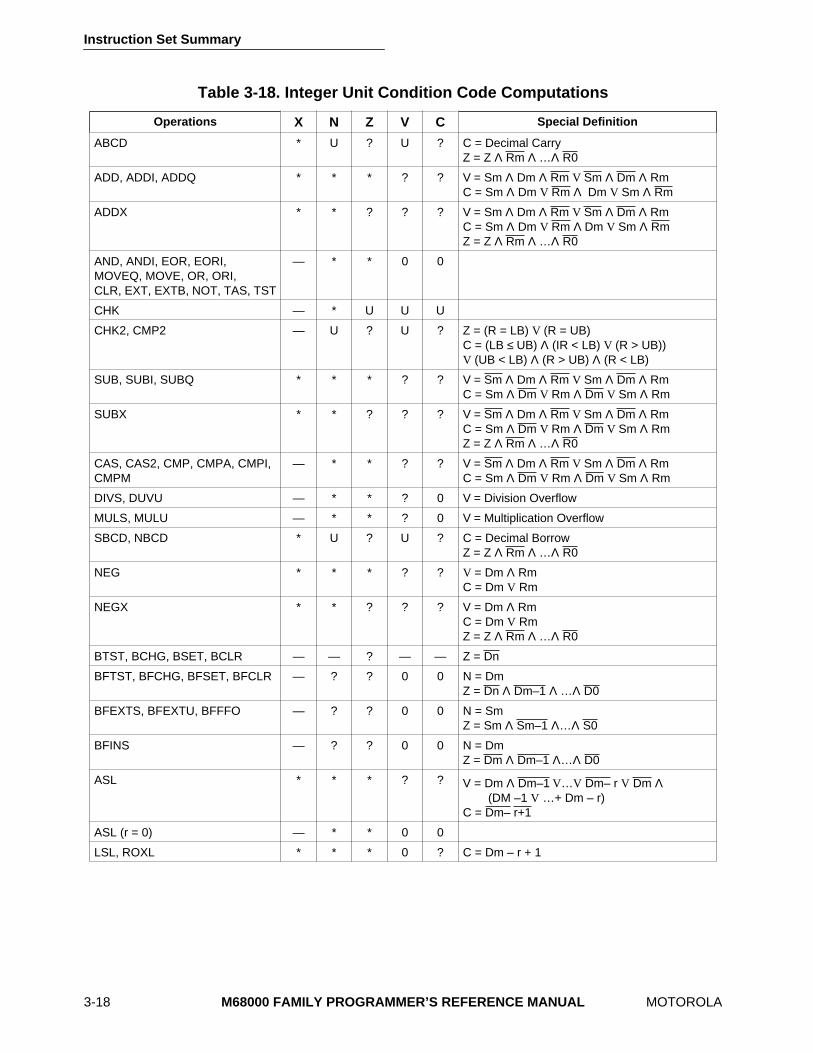
3.2 INTEGER UNIT CONDITION CODE COMPUTATION
Many integer instructions affect the CCR to indicate the instruction,s results. Program andsystem control instructions also use certain combinations of these bits to control programand system flow. The condition codes meet consistency criteria across instructions, uses,and instances. They also meet the criteria of meaningful results, where no change occursunless it provides useful information. Refer to Section 1 Introduction for details concerningthe CCR.
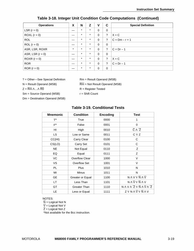
Table 3-18 lists the integer condition code computations for instructions and Table 3-19 liststhe condition names, encodings, and tests for the conditional branch and set instructions.The test associated with each condition is a logical formula using the current states of thecondition codes. If this formula evaluates to one, the condition is true. If the formulaevaluates to zero, the condition is false. For example, the T condition is always true, and theEQ condition is true only if the Z-bit condition code is currently true.
Table 3-17. Monadic Floating-Point Operations
Instruction Operation Instruction Operation
FABS Absolute Value FLOGN In(x)
FACOS Arc Cosine FLOGNP1 In(x + 1)
FASIN Arc Sine FLOG10 Log10(x)
FATAN Hyperbolic Art Tangent FLOG2 Log2(x)
FCOS Cosine FNEG Negate
FCOSH Hyperbolic Cosine FSIN Sine
FETOX ex FSINH Hyperbolic Sine
FETOXM1 ex – 1 FSQRT Square Root
FGETEXP Extract Exponent FTAN Tangent
FGETMAN Extract Mantissa FTANH Hyperbolic Tangent
FINT Extract Integer Part FTENTOX 10x
FINTRZ Extract Integer Part, Rounded-to-Zero FTWOTOX 2x
Instruction Set Summary
3-18 M68000 FAMILY PROGRAMMER’S REFERENCE MANUAL MOTOROLA
Table 3-18. Integer Unit Condition Code Computations
Operations X N Z V C Special Definition
ABCD * U ? U ? C = Decimal CarryZ = Z Λ Rm Λ …Λ R0
ADD, ADDI, ADDQ * * * ? ? V = Sm Λ Dm Λ Rm V Sm Λ Dm Λ RmC = Sm Λ Dm V Rm Λ Dm V Sm Λ Rm
ADDX * * ? ? ? V = Sm Λ Dm Λ Rm V Sm Λ Dm Λ RmC = Sm Λ Dm V Rm Λ Dm V Sm Λ RmZ = Z Λ Rm Λ …Λ R0
AND, ANDI, EOR, EORI,MOVEQ, MOVE, OR, ORI,CLR, EXT, EXTB, NOT, TAS, TST
— * * 0 0
CHK — * U U U
CHK2, CMP2 — U ? U ? Z = (R = LB) V (R = UB)C = (LB ≤ UB) Λ (IR < LB) V (R > UB))V (UB < LB) Λ (R > UB) Λ (R < LB)
SUB, SUBI, SUBQ * * * ? ? V = Sm Λ Dm Λ Rm V Sm Λ Dm Λ RmC = Sm Λ Dm V Rm Λ Dm V Sm Λ Rm
SUBX * * ? ? ? V = Sm Λ Dm Λ Rm V Sm Λ Dm Λ RmC = Sm Λ Dm V Rm Λ Dm V Sm Λ RmZ = Z Λ Rm Λ …Λ R0
CAS, CAS2, CMP, CMPA, CMPI, CMPM
— * * ? ? V = Sm Λ Dm Λ Rm V Sm Λ Dm Λ RmC = Sm Λ Dm V Rm Λ Dm V Sm Λ Rm
DIVS, DUVU — * * ? 0 V = Division Overflow
MULS, MULU — * * ? 0 V = Multiplication Overflow
SBCD, NBCD * U ? U ? C = Decimal BorrowZ = Z Λ Rm Λ …Λ R0
NEG * * * ? ? V = Dm Λ RmC = Dm V Rm
NEGX * * ? ? ? V = Dm Λ RmC = Dm V RmZ = Z Λ Rm Λ …Λ R0
BTST, BCHG, BSET, BCLR — — ? — — Z = Dn
BFTST, BFCHG, BFSET, BFCLR — ? ? 0 0 N = DmZ = Dn Λ Dm–1 Λ …Λ D0
BFEXTS, BFEXTU, BFFFO — ? ? 0 0 N = SmZ = Sm Λ Sm–1 Λ…Λ S0
BFINS — ? ? 0 0 N = DmZ = Dm Λ Dm–1 Λ…Λ D0
ASL * * * ? ? V = Dm Λ Dm–1 V…V Dm– r V Dm Λ(DM –1 V …+ Dm – r)
C = Dm– r+1
ASL (r = 0) — * * 0 0
LSL, ROXL * * * 0 ? C = Dm – r + 1
Instruction Set Summary
MOTOROLA M68000 FAMILY PROGRAMMER’S REFERENCE MANUAL 3-19
NOTES:N = Logical Not NV = Logical Not VZ = Logical Not Z*Not available for the Bcc instruction.
LSR (r = 0) — * * 0 0
ROXL (r = 0) — * * 0 ? X = C
ROL — * * 0 ? C = Dm – r + 1
ROL (r = 0) — * * 0 0
ASR, LSR, ROXR * * * 0 ? C = Dr – 1
ASR, LSR (r = 0) — * * 0 0
ROXR (r = 0) — * * 0 ? X = C
ROR — * * 0 ? C = Dr – 1
ROR (r = 0) — * * 0 0
? = Other—See Special Definition Rm = Result Operand (MSB)
N = Result Operand (MSB) Rm = Not Result Operand (MSB)
Z = Rm Λ…Λ R0 R = Register Tested
Sm = Source Operand (MSB) r = Shift Count
Dm = Destination Operand (MSB)
Table 3-19. Conditional Tests
Mnemonic Condition Encoding Test
T* True 0000 1
F* False 0001 0
HI High 0010 C Λ Z
LS Low or Same 0011 C V Z
CC(HI) Carry Clear 0100 C
CS(LO) Carry Set 0101 C
NE Not Equal 0110 Z
EQ Equal 0111 Z
VC Overflow Clear 1000 V
VS Overflow Set 1001 V
PL Plus 1010 N
MI Minus 1011 N
GE Greater or Equal 1100 N Λ V V N Λ V
LT Less Than 1101 N Λ V V N Λ V
GT Greater Than 1110 N Λ V Λ Z V N Λ V Λ Z
LE Less or Equal 1111 Z V N Λ V V N Λ V
Table 3-18. Integer Unit Condition Code Computations (Continued)
Operations X N Z V C Special Definition
Instruction Set Summary
3-32 M68000 FAMILY PROGRAMMER’S REFERENCE MANUAL MOTOROLA
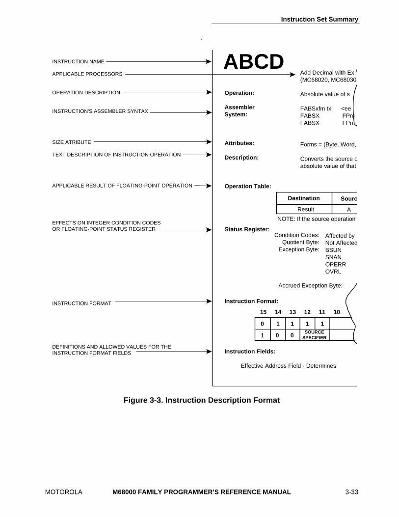
3.7 INSTRUCTION DESCRIPTIONS
Section 4, 5, 6, and 7 contain detailed information about each instruction in the M68000family instruction set. Each section arranges the instruction in alphabetical order byinstruction mnemonic and includes descriptions of the instruction’s notation and format.Figure 3-3 illustrates the format of the instruction descriptions. Note that the illustration is anamalgamation of the various parts that make up an instruction description. Instructiondescriptions for the integer unit differ slightly from those for the floating-point unit; i.e. thereare no operation tables included for integer unit instruction descriptions.
The size attribute line specifies the size of the operands of an instruction. When aninstruction uses operands of more than one size, the mnemonic of the instruction includesa suffix such as:
.B—Byte Operands
.W—Word Operands
.L—Long-Word Operands
.S—Single-Precision Real Operands
.D—Double-Precision Real Operands
.X—Extended-Precision Real Operands
.P—Packed BCD Real Operands
The instruction format specifies the bit pattern and fields of the operation and commandwords, and any other words that are always part of the instruction. The effective addressextensions are not explicitly illustrated. The extension words, if any, follow immediately afterthe illustrated portions of the instructions.
Instruction Set Summary
MOTOROLA M68000 FAMILY PROGRAMMER’S REFERENCE MANUAL 3-33
.
Figure 3-3. Instruction Description Format
ABCDOperation: Assembler System: Attributes: Description: Operation Table: Status Register: Instruction Format: Instruction Fields: Effective Address Field - Determines
Add Decimal with Ex (MC68020, MC68030, Absolute value of s FABSxfm tx <ee FABSX FPm FABSX FPn Forms = (Byte, Word, Converts the source oabsolute value of that
Result
Destination Sourc
A
NOTE: If the source operation
Condition Codes: Quotient Byte:
Exception Byte:
Affected by Not AffectedBSUN SNAN OPERR OVRL
Accrued Exception Byte:
15 14 13 12 11 10
0
0 0
1
1
1 1 1SOURCE
SPECIFIER
INSTRUCTION NAME APPLICABLE PROCESSORS OPERATION DESCRIPTION INSTRUCTION'S ASSEMBLER SYNTAX SIZE ATRIBUTE TEXT DESCRIPTION OF INSTRUCTION OPERATION APPLICABLE RESULT OF FLOATING-POINT OPERATION EFFECTS ON INTEGER CONDITION CODES OR FLOATING-POINT STATUS REGISTER INSTRUCTION FORMAT DEFINITIONS AND ALLOWED VALUES FOR THE INSTRUCTION FORMAT FIELDS

Integer Instructions
4-4
M68000 FAMILY PROGRAMMER’S REFERENCE MANUAL
MOTOROLA
ADD
Add
ADD
(M68000 Family)
Operation:
Source + Destination
→
Destination
Assembler
ADD < ea > ,Dn
Syntax:
ADD Dn, < ea >
Attributes:
Size = (Byte, Word, Long)
Description:
Adds the source operand to the destination operand using binary addition andstores the result in the destination location. The size of the operation may be specifiedas byte, word, or long. The mode of the instruction indicates which operand is thesource and which is the destination, as well as the operand size.
Condition Codes:
X — Set the same as the carry bit. N — Set if the result is negative; cleared otherwise. Z — Set if the result is zero; cleared otherwise. V — Set if an overflow is generated; cleared otherwise. C — Set if a carry is generated; cleared otherwise.
Instruction Format:
X N Z V C
∗ ∗ ∗ ∗ ∗
15 14 13 12 11 10 9 8 7 6 5 4 3 2 1 0
1 1 0 1 REGISTER OPMODEEFFECTIVE ADDRESS
MODE REGISTER
Integer Instructions
MOTOROLA
M68000 FAMILY PROGRAMMER’S REFERENCE MANUAL
4-5
ADD
Add
ADD
(M68000 Family)
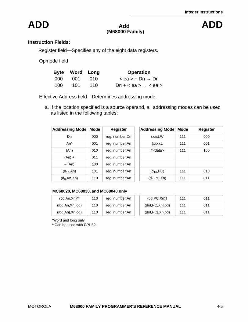
Instruction Fields:
Register field—Specifies any of the eight data registers.
Opmode field
Effective Address field—Determines addressing mode.
a. If the location specified is a source operand, all addressing modes can be used as listed in the following tables:
*Word and long only**Can be used with CPU32.
Byte Word Long Operation
000 001 010 < ea > + Dn
→
Dn 100 101 110 Dn + < ea >
→
< ea >
Addressing Mode Mode Register Addressing Mode Mode Register
Dn 000 reg. number:Dn (xxx).W 111 000
An* 001 reg. number:An (xxx).L 111 001
(An) 010 reg. number:An #<data> 111 100
(An) + 011 reg. number:An
– (An) 100 reg. number:An
(d
16
,An) 101 reg. number:An (d
16
,PC) 111 010
(d
8
,An,Xn) 110 reg. number:An (d
8
,PC,Xn) 111 011
MC68020, MC68030, and MC68040 only
(bd,An,Xn)** 110 reg. number:An (bd,PC,Xn)† 111 011
([bd,An,Xn],od) 110 reg. number:An ([bd,PC,Xn],od) 111 011
([bd,An],Xn,od) 110 reg. number:An ([bd,PC],Xn,od) 111 011
Integer Instructions
4-6
M68000 FAMILY PROGRAMMER’S REFERENCE MANUAL
MOTOROLA
ADD
Add
ADD
(M68000 Family)
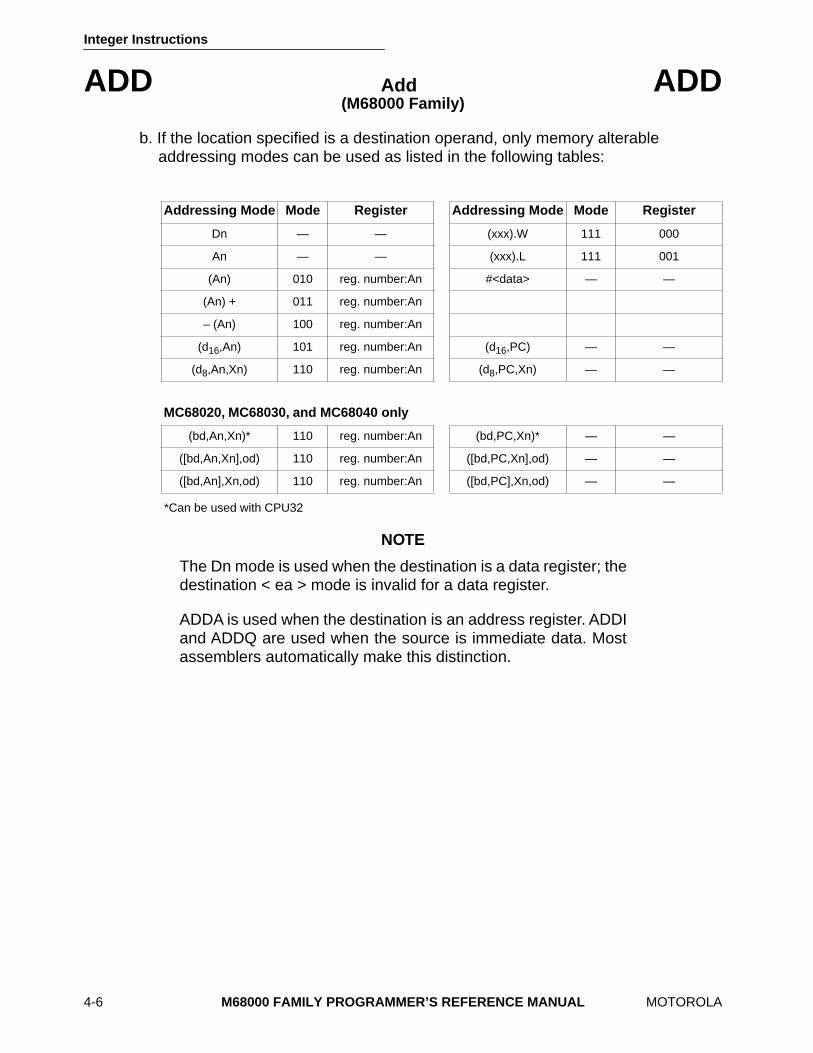
b. If the location specified is a destination operand, only memory alterable addressing modes can be used as listed in the following tables:
*Can be used with CPU32
NOTE
The Dn mode is used when the destination is a data register; thedestination < ea > mode is invalid for a data register.
ADDA is used when the destination is an address register. ADDIand ADDQ are used when the source is immediate data. Mostassemblers automatically make this distinction.
Addressing Mode Mode Register Addressing Mode Mode Register
Dn — — (xxx).W 111 000
An — — (xxx).L 111 001
(An) 010 reg. number:An #<data> — —
(An) + 011 reg. number:An
– (An) 100 reg. number:An
(d
16
,An) 101 reg. number:An (d
16
,PC) — —
(d
8
,An,Xn) 110 reg. number:An (d
8
,PC,Xn) — —
MC68020, MC68030, and MC68040 only
(bd,An,Xn)* 110 reg. number:An (bd,PC,Xn)* — —
([bd,An,Xn],od) 110 reg. number:An ([bd,PC,Xn],od) — —
([bd,An],Xn,od) 110 reg. number:An ([bd,PC],Xn,od) — —
Integer Instructions
MOTOROLA
M68000 FAMILY PROGRAMMER’S REFERENCE MANUAL
4-7
ADDA
Add Address
ADDA
(M68000 Family)
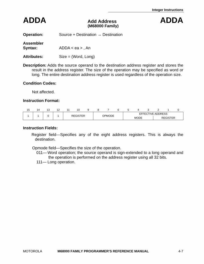
Operation:
Source + Destination
→
Destination
Assembler Syntax:
ADDA < ea > , An
Attributes:
Size = (Word, Long)
Description:
Adds the source operand to the destination address register and stores theresult in the address register. The size of the operation may be specified as word orlong. The entire destination address register is used regardless of the operation size.
Condition Codes:
Not affected.
Instruction Format:
Instruction Fields:
Register field—Specifies any of the eight address registers. This is always thedestination.
Opmode field—Specifies the size of the operation. 011— Word operation; the source operand is sign-extended to a long operand and
the operation is performed on the address register using all 32 bits. 111— Long operation.
15 14 13 12 11 10 9 8 7 6 5 4 3 2 1 0
1 1 0 1 REGISTER OPMODEEFFECTIVE ADDRESS
MODE REGISTER
Integer Instructions
4-8
M68000 FAMILY PROGRAMMER’S REFERENCE MANUAL
MOTOROLA
ADDA
Add Address
ADDA
(M68000 Family)
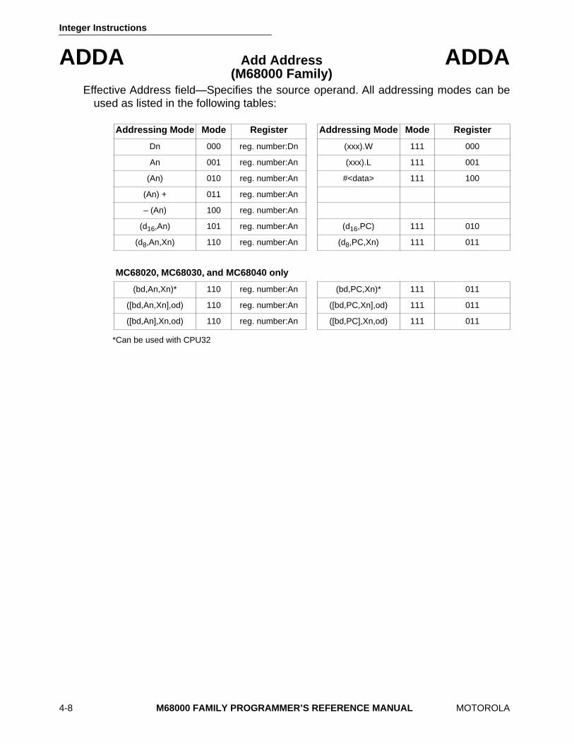
Effective Address field—Specifies the source operand. All addressing modes can beused as listed in the following tables:
*Can be used with CPU32
Addressing Mode Mode Register Addressing Mode Mode Register
Dn 000 reg. number:Dn (xxx).W 111 000
An 001 reg. number:An (xxx).L 111 001
(An) 010 reg. number:An #<data> 111 100
(An) + 011 reg. number:An
– (An) 100 reg. number:An
(d
16
,An) 101 reg. number:An (d
16
,PC) 111 010
(d
8
,An,Xn) 110 reg. number:An (d
8
,PC,Xn) 111 011
MC68020, MC68030, and MC68040 only
(bd,An,Xn)* 110 reg. number:An (bd,PC,Xn)* 111 011
([bd,An,Xn],od) 110 reg. number:An ([bd,PC,Xn],od) 111 011
([bd,An],Xn,od) 110 reg. number:An ([bd,PC],Xn,od) 111 011
Integer Instructions
MOTOROLA
M68000 FAMILY PROGRAMMER’S REFERENCE MANUAL
4-9
ADDI
Add Immediate
ADDI
(M68000 Family)
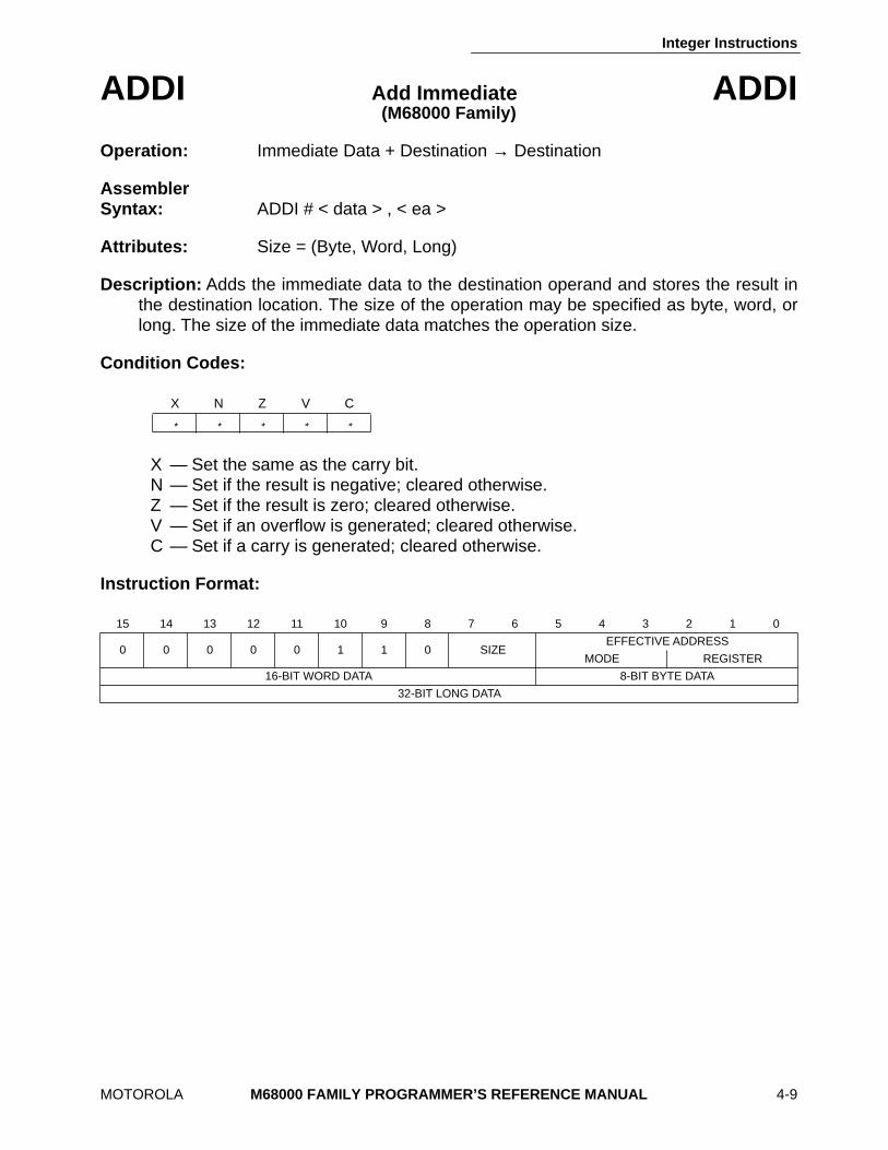
Operation:
Immediate Data + Destination → Destination
Assembler Syntax: ADDI # < data > , < ea >
Attributes: Size = (Byte, Word, Long)
Description: Adds the immediate data to the destination operand and stores the result inthe destination location. The size of the operation may be specified as byte, word, orlong. The size of the immediate data matches the operation size.
Condition Codes:
X — Set the same as the carry bit. N — Set if the result is negative; cleared otherwise. Z — Set if the result is zero; cleared otherwise. V — Set if an overflow is generated; cleared otherwise. C — Set if a carry is generated; cleared otherwise.
Instruction Format:
X N Z V C
* * * * *
15 14 13 12 11 10 9 8 7 6 5 4 3 2 1 0
0 0 0 0 0 1 1 0 SIZEEFFECTIVE ADDRESS
MODE REGISTER
16-BIT WORD DATA 8-BIT BYTE DATA
32-BIT LONG DATA
Integer Instructions
4-10 M68000 FAMILY PROGRAMMER’S REFERENCE MANUAL MOTOROLA
ADDI Add Immediate ADDI (M68000 Family)
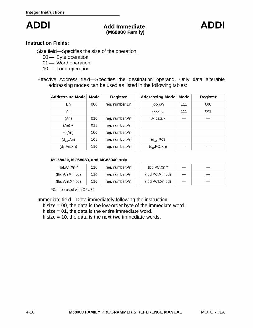
Instruction Fields:
Size field—Specifies the size of the operation. 00 — Byte operation 01 — Word operation 10 — Long operation
Effective Address field—Specifies the destination operand. Only data alterableaddressing modes can be used as listed in the following tables:
*Can be used with CPU32
Immediate field—Data immediately following the instruction. If size = 00, the data is the low-order byte of the immediate word. If size = 01, the data is the entire immediate word. If size = 10, the data is the next two immediate words.
Addressing Mode Mode Register Addressing Mode Mode Register
Dn 000 reg. number:Dn (xxx).W 111 000
An — — (xxx).L 111 001
(An) 010 reg. number:An #<data> — —
(An) + 011 reg. number:An
– (An) 100 reg. number:An
(d16,An) 101 reg. number:An (d16,PC) — —
(d8,An,Xn) 110 reg. number:An (d8,PC,Xn) — —
MC68020, MC68030, and MC68040 only
(bd,An,Xn)* 110 reg. number:An (bd,PC,Xn)* — —
([bd,An,Xn],od) 110 reg. number:An ([bd,PC,Xn],od) — —
([bd,An],Xn,od) 110 reg. number:An ([bd,PC],Xn,od) — —

Integer Instructions
MOTOROLA M68000 FAMILY PROGRAMMER’S REFERENCE MANUAL 4-11
ADDQ Add Quick ADDQ (M68000 Family)
Operation: Immediate Data + Destination → Destination
Assembler Syntax: ADDQ # < data > , < ea >
Attributes: Size = (Byte, Word, Long)
Description: Adds an immediate value of one to eight to the operand at the destinationlocation. The size of the operation may be specified as byte, word, or long. Word andlong operations are also allowed on the address registers. When adding to addressregisters, the condition codes are not altered, and the entire destination addressregister is used regardless of the operation size.
Condition Codes:
X — Set the same as the carry bit. N — Set if the result is negative; cleared otherwise. Z — Set if the result is zero; cleared otherwise. V — Set if an overflow occurs; cleared otherwise. C — Set if a carry occurs; cleared otherwise.
The condition codes are not affected when the destination is an address register.
Instruction Format:
X N Z V C
* * * * *
15 14 13 12 11 10 9 8 7 6 5 4 3 2 1 0
0 1 0 1 DATA 0 SIZEEFFECTIVE ADDRESS
MODE REGISTER
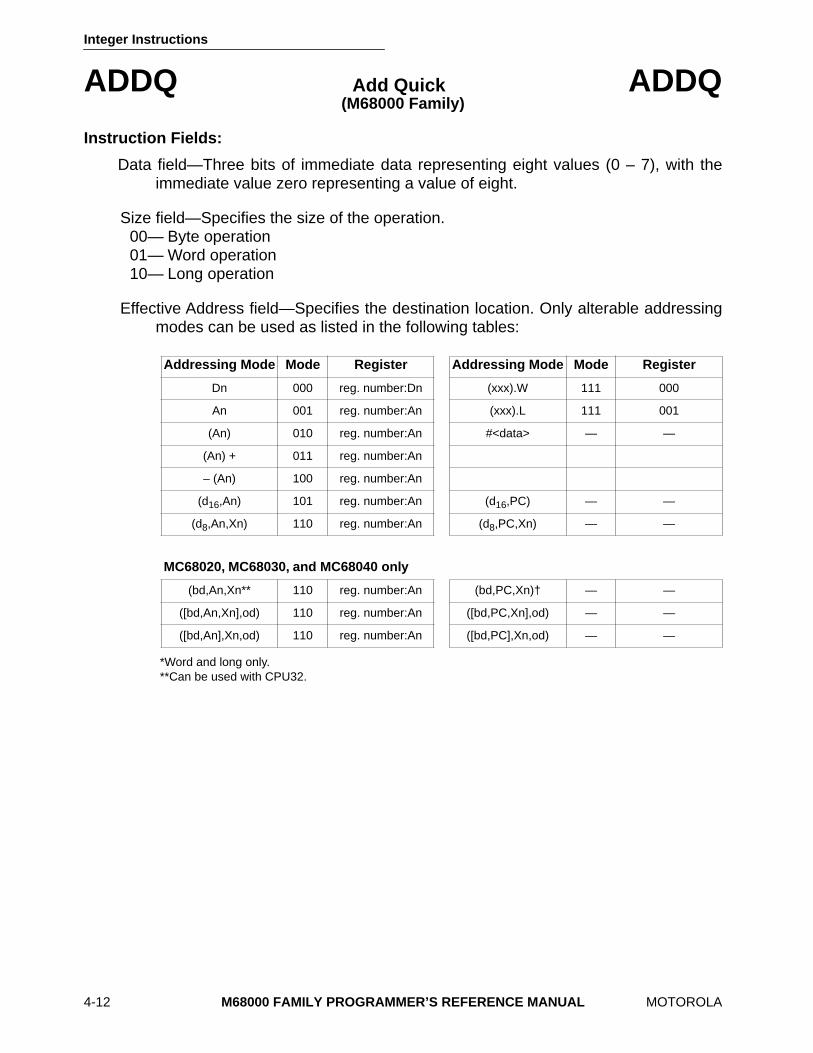
Integer Instructions
4-12 M68000 FAMILY PROGRAMMER’S REFERENCE MANUAL MOTOROLA
ADDQ Add Quick ADDQ (M68000 Family)
Instruction Fields:
Data field—Three bits of immediate data representing eight values (0 – 7), with theimmediate value zero representing a value of eight.
Size field—Specifies the size of the operation. 00— Byte operation 01— Word operation 10— Long operation
Effective Address field—Specifies the destination location. Only alterable addressingmodes can be used as listed in the following tables:
*Word and long only.**Can be used with CPU32.
Addressing Mode Mode Register Addressing Mode Mode Register
Dn 000 reg. number:Dn (xxx).W 111 000
An 001 reg. number:An (xxx).L 111 001
(An) 010 reg. number:An #<data> — —
(An) + 011 reg. number:An
– (An) 100 reg. number:An
(d16,An) 101 reg. number:An (d16,PC) — —
(d8,An,Xn) 110 reg. number:An (d8,PC,Xn) — —
MC68020, MC68030, and MC68040 only
(bd,An,Xn** 110 reg. number:An (bd,PC,Xn)† — —
([bd,An,Xn],od) 110 reg. number:An ([bd,PC,Xn],od) — —
([bd,An],Xn,od) 110 reg. number:An ([bd,PC],Xn,od) — —
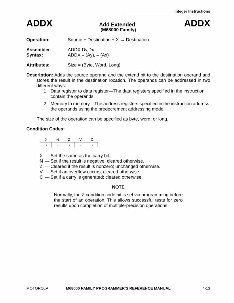
Integer Instructions
MOTOROLA M68000 FAMILY PROGRAMMER’S REFERENCE MANUAL 4-13
ADDX Add Extended ADDX (M68000 Family)
Operation: Source + Destination + X → Destination
Assembler ADDX Dy,Dx Syntax: ADDX – (Ay), – (Ax)
Attributes: Size = (Byte, Word, Long)
Description: Adds the source operand and the extend bit to the destination operand andstores the result in the destination location. The operands can be addressed in twodifferent ways:
1. Data register to data register—The data registers specified in the instruction contain the operands.
2. Memory to memory—The address registers specified in the instruction address the operands using the predecrement addressing mode.
The size of the operation can be specified as byte, word, or long.
Condition Codes:
X — Set the same as the carry bit. N — Set if the result is negative; cleared otherwise. Z — Cleared if the result is nonzero; unchanged otherwise. V — Set if an overflow occurs; cleared otherwise. C — Set if a carry is generated; cleared otherwise.
NOTE
Normally, the Z condition code bit is set via programming beforethe start of an operation. This allows successful tests for zeroresults upon completion of multiple-precision operations.
X N Z V C
* * * * *
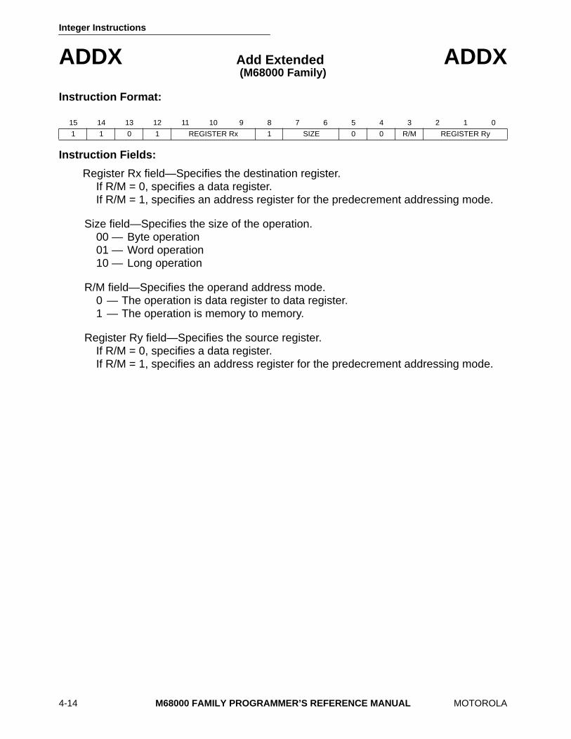
Integer Instructions
4-14 M68000 FAMILY PROGRAMMER’S REFERENCE MANUAL MOTOROLA
ADDX Add Extended ADDX (M68000 Family)
Instruction Format:
Instruction Fields:
Register Rx field—Specifies the destination register. If R/M = 0, specifies a data register. If R/M = 1, specifies an address register for the predecrement addressing mode.
Size field—Specifies the size of the operation. 00 — Byte operation 01 — Word operation 10 — Long operation
R/M field—Specifies the operand address mode. 0 — The operation is data register to data register. 1 — The operation is memory to memory.
Register Ry field—Specifies the source register. If R/M = 0, specifies a data register. If R/M = 1, specifies an address register for the predecrement addressing mode.
15 14 13 12 11 10 9 8 7 6 5 4 3 2 1 0
1 1 0 1 REGISTER Rx 1 SIZE 0 0 R/M REGISTER Ry
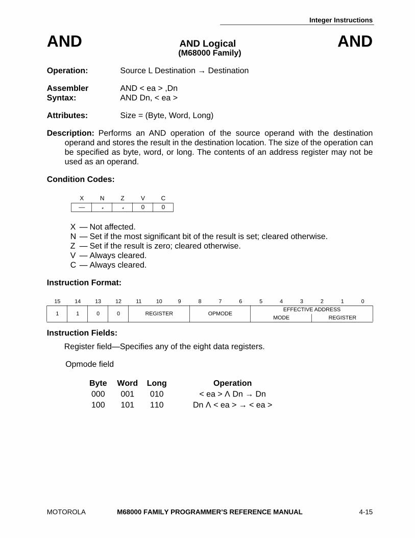
Integer Instructions
MOTOROLA M68000 FAMILY PROGRAMMER’S REFERENCE MANUAL 4-15
AND AND Logical AND(M68000 Family)
Operation: Source L Destination → Destination
Assembler AND < ea > ,Dn Syntax: AND Dn, < ea >
Attributes: Size = (Byte, Word, Long)
Description: Performs an AND operation of the source operand with the destinationoperand and stores the result in the destination location. The size of the operation canbe specified as byte, word, or long. The contents of an address register may not beused as an operand.
Condition Codes:
X — Not affected. N — Set if the most significant bit of the result is set; cleared otherwise. Z — Set if the result is zero; cleared otherwise. V — Always cleared. C — Always cleared.
Instruction Format:
Instruction Fields:
Register field—Specifies any of the eight data registers.
Opmode field
X N Z V C — * * 0 0
15 14 13 12 11 10 9 8 7 6 5 4 3 2 1 0
1 1 0 0 REGISTER OPMODEEFFECTIVE ADDRESS
MODE REGISTER
Byte Word Long Operation 000 001 010 < ea > Λ Dn → Dn 100 101 110 Dn Λ < ea > → < ea >
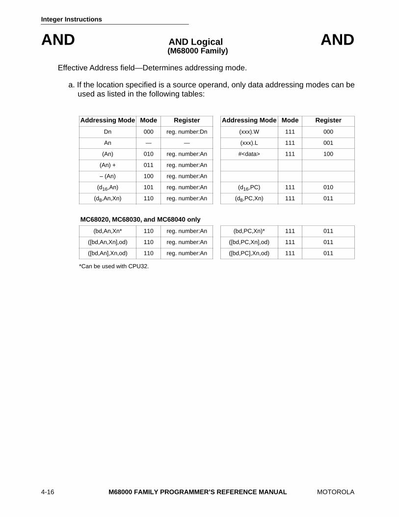
Integer Instructions
4-16 M68000 FAMILY PROGRAMMER’S REFERENCE MANUAL MOTOROLA
AND AND Logical AND (M68000 Family)
Effective Address field—Determines addressing mode.
a. If the location specified is a source operand, only data addressing modes can beused as listed in the following tables:
*Can be used with CPU32.
Addressing Mode Mode Register Addressing Mode Mode Register
Dn 000 reg. number:Dn (xxx).W 111 000
An — — (xxx).L 111 001
(An) 010 reg. number:An #<data> 111 100
(An) + 011 reg. number:An
– (An) 100 reg. number:An
(d16,An) 101 reg. number:An (d16,PC) 111 010
(d8,An,Xn) 110 reg. number:An (d8,PC,Xn) 111 011
MC68020, MC68030, and MC68040 only
(bd,An,Xn* 110 reg. number:An (bd,PC,Xn)* 111 011
([bd,An,Xn],od) 110 reg. number:An ([bd,PC,Xn],od) 111 011
([bd,An],Xn,od) 110 reg. number:An ([bd,PC],Xn,od) 111 011
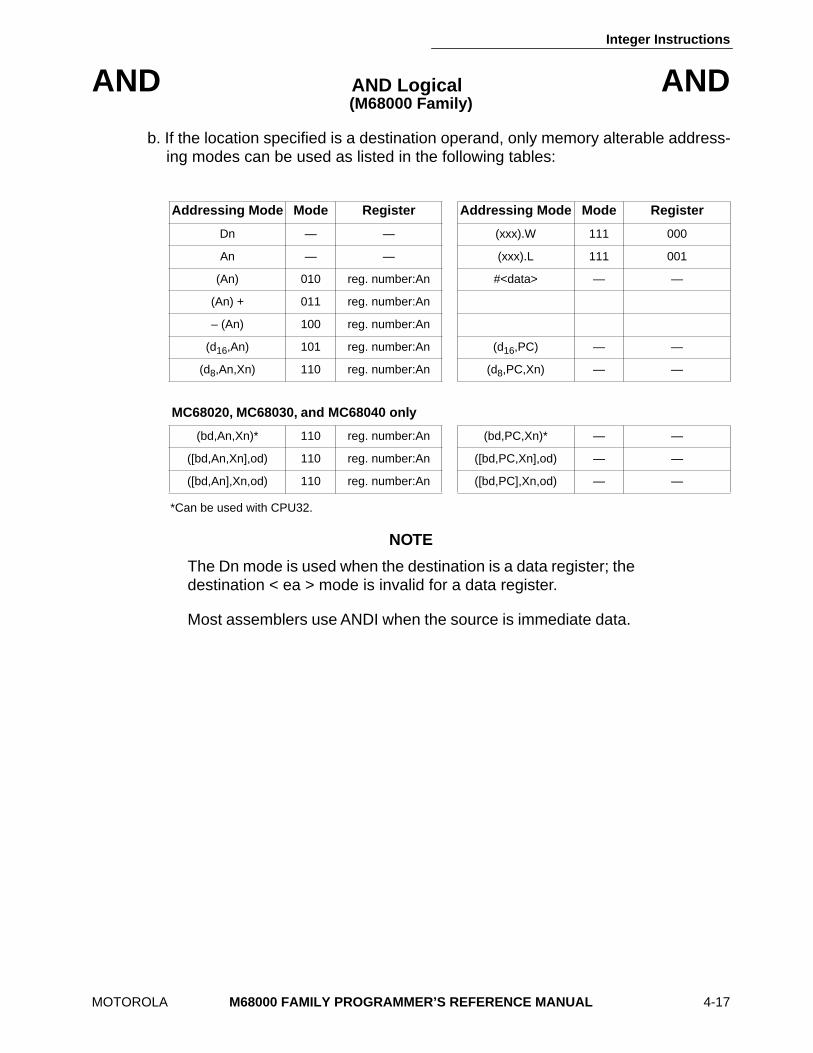
Integer Instructions
MOTOROLA M68000 FAMILY PROGRAMMER’S REFERENCE MANUAL 4-17
AND AND Logical AND (M68000 Family)
b. If the location specified is a destination operand, only memory alterable address-ing modes can be used as listed in the following tables:
*Can be used with CPU32.
NOTE
The Dn mode is used when the destination is a data register; thedestination < ea > mode is invalid for a data register.
Most assemblers use ANDI when the source is immediate data.
Addressing Mode Mode Register Addressing Mode Mode Register
Dn — — (xxx).W 111 000
An — — (xxx).L 111 001
(An) 010 reg. number:An #<data> — —
(An) + 011 reg. number:An
– (An) 100 reg. number:An
(d16,An) 101 reg. number:An (d16,PC) — —
(d8,An,Xn) 110 reg. number:An (d8,PC,Xn) — —
MC68020, MC68030, and MC68040 only
(bd,An,Xn)* 110 reg. number:An (bd,PC,Xn)* — —
([bd,An,Xn],od) 110 reg. number:An ([bd,PC,Xn],od) — —
([bd,An],Xn,od) 110 reg. number:An ([bd,PC],Xn,od) — —
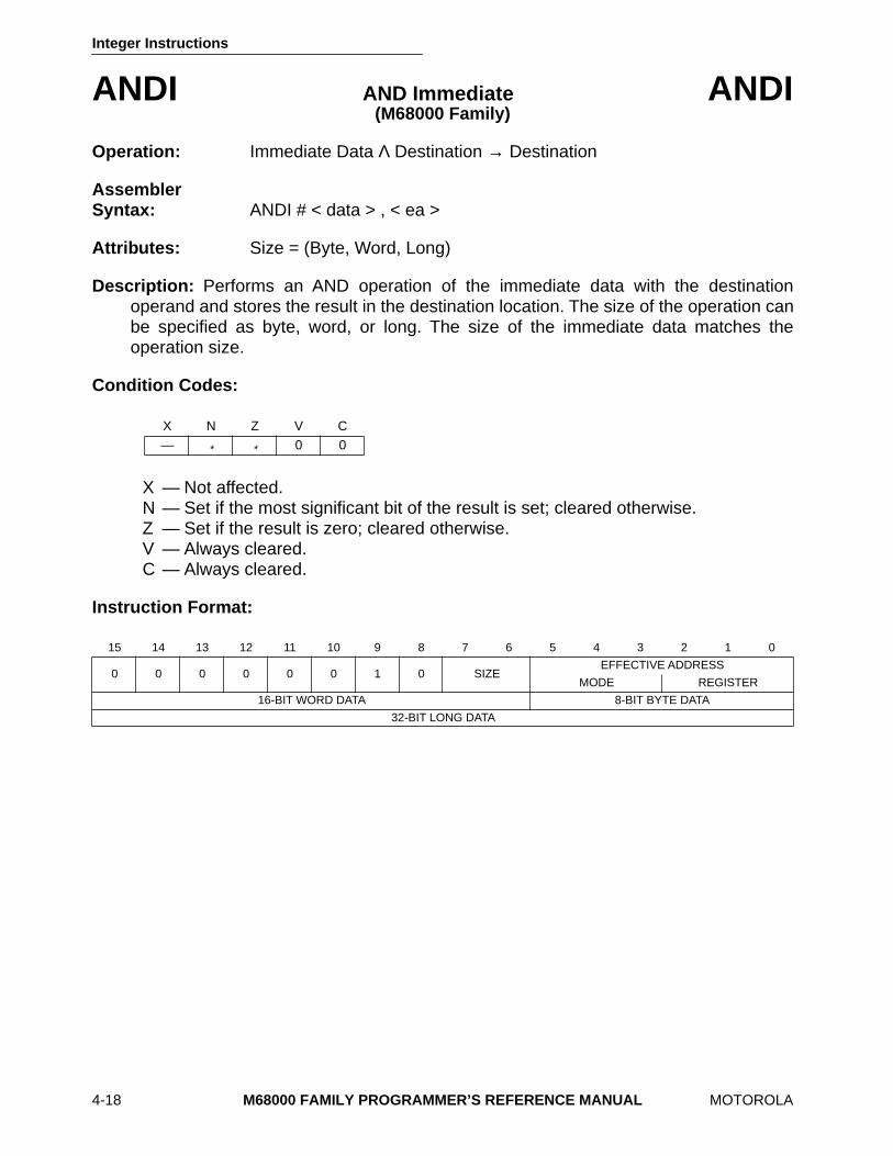
Integer Instructions
4-18 M68000 FAMILY PROGRAMMER’S REFERENCE MANUAL MOTOROLA
ANDI AND Immediate ANDI (M68000 Family)
Operation: Immediate Data Λ Destination → Destination
Assembler Syntax: ANDI # < data > , < ea >
Attributes: Size = (Byte, Word, Long)
Description: Performs an AND operation of the immediate data with the destinationoperand and stores the result in the destination location. The size of the operation canbe specified as byte, word, or long. The size of the immediate data matches theoperation size.
Condition Codes:
X — Not affected. N — Set if the most significant bit of the result is set; cleared otherwise. Z — Set if the result is zero; cleared otherwise. V — Always cleared. C — Always cleared.
Instruction Format:
X N Z V C — * * 0 0
15 14 13 12 11 10 9 8 7 6 5 4 3 2 1 0
0 0 0 0 0 0 1 0 SIZEEFFECTIVE ADDRESS
MODE REGISTER
16-BIT WORD DATA 8-BIT BYTE DATA
32-BIT LONG DATA

Integer Instructions
MOTOROLA M68000 FAMILY PROGRAMMER’S REFERENCE MANUAL 4-19
ANDI AND Immediate ANDI (M68000 Family)
Instruction Fields:
Size field—Specifies the size of the operation. 00 — Byte operation 01 — Word operation 10 — Long operation
Effective Address field—Specifies the destination operand. Only data alterableaddressing modes can be used as listed in the following tables:
*Can be used with CPU32
Immediate field—Data immediately following the instruction. If size = 00, the data is the low-order byte of the immediate word. If size = 01, the data is the entire immediate word. If size = 10, the data is the next two immediate words.
Addressing Mode Mode Register Addressing Mode Mode Register
Dn 000 reg. number:Dn (xxx).W 111 000
An — — (xxx).L 111 001
(An) 010 reg. number:An #<data> — —
(An) + 011 reg. number:An
– (An) 100 reg. number:An
(d16,An) 101 reg. number:An (d16,PC) — —
(d8,An,Xn) 110 reg. number:An (d8,PC,Xn) — —
MC68020, MC68030, and MC68040 only
(bd,An,Xn)* 110 reg. number:An (bd,PC,Xn)* — —
([bd,An,Xn],od) 110 reg. number:An ([bd,PC,Xn],od) — —
([bd,An],Xn,od) 110 reg. number:An ([bd,PC],Xn,od) — —
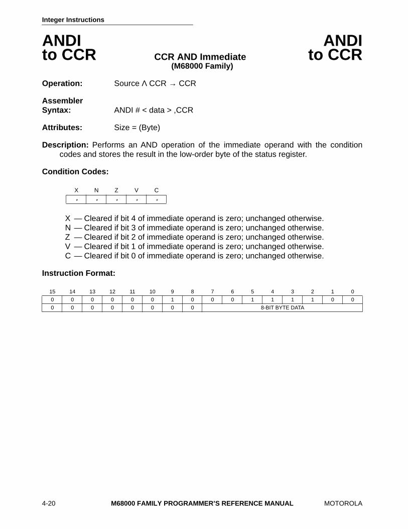
Integer Instructions
4-20 M68000 FAMILY PROGRAMMER’S REFERENCE MANUAL MOTOROLA
ANDI ANDI to CCR CCR AND Immediate to CCR
(M68000 Family)
Operation: Source Λ CCR → CCR
Assembler Syntax: ANDI # < data > ,CCR
Attributes: Size = (Byte)
Description: Performs an AND operation of the immediate operand with the conditioncodes and stores the result in the low-order byte of the status register.
Condition Codes:
X — Cleared if bit 4 of immediate operand is zero; unchanged otherwise. N — Cleared if bit 3 of immediate operand is zero; unchanged otherwise. Z — Cleared if bit 2 of immediate operand is zero; unchanged otherwise. V — Cleared if bit 1 of immediate operand is zero; unchanged otherwise. C — Cleared if bit 0 of immediate operand is zero; unchanged otherwise.
Instruction Format:
X N Z V C
* * * * *
15 14 13 12 11 10 9 8 7 6 5 4 3 2 1 0
0 0 0 0 0 0 1 0 0 0 1 1 1 1 0 0
0 0 0 0 0 0 0 0 8-BIT BYTE DATA
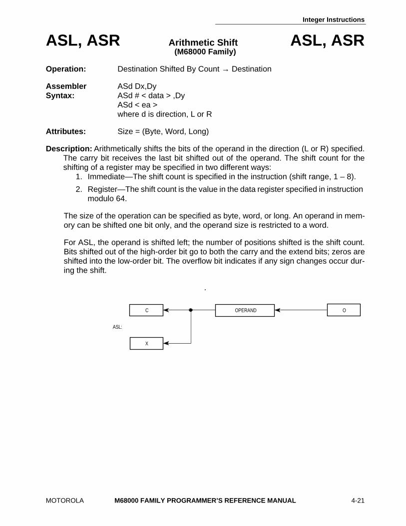
Integer Instructions
MOTOROLA M68000 FAMILY PROGRAMMER’S REFERENCE MANUAL 4-21
ASL, ASR Arithmetic Shift ASL, ASR(M68000 Family)
Operation: Destination Shifted By Count → Destination
Assembler ASd Dx,Dy Syntax: ASd # < data > ,Dy
ASd < ea > where d is direction, L or R
Attributes: Size = (Byte, Word, Long)
Description: Arithmetically shifts the bits of the operand in the direction (L or R) specified.The carry bit receives the last bit shifted out of the operand. The shift count for theshifting of a register may be specified in two different ways:
1. Immediate—The shift count is specified in the instruction (shift range, 1 – 8).
2. Register—The shift count is the value in the data register specified in instruction modulo 64.
The size of the operation can be specified as byte, word, or long. An operand in mem-ory can be shifted one bit only, and the operand size is restricted to a word.
For ASL, the operand is shifted left; the number of positions shifted is the shift count.Bits shifted out of the high-order bit go to both the carry and the extend bits; zeros areshifted into the low-order bit. The overflow bit indicates if any sign changes occur dur-ing the shift.
.
C OPERAND O
X
ASL:
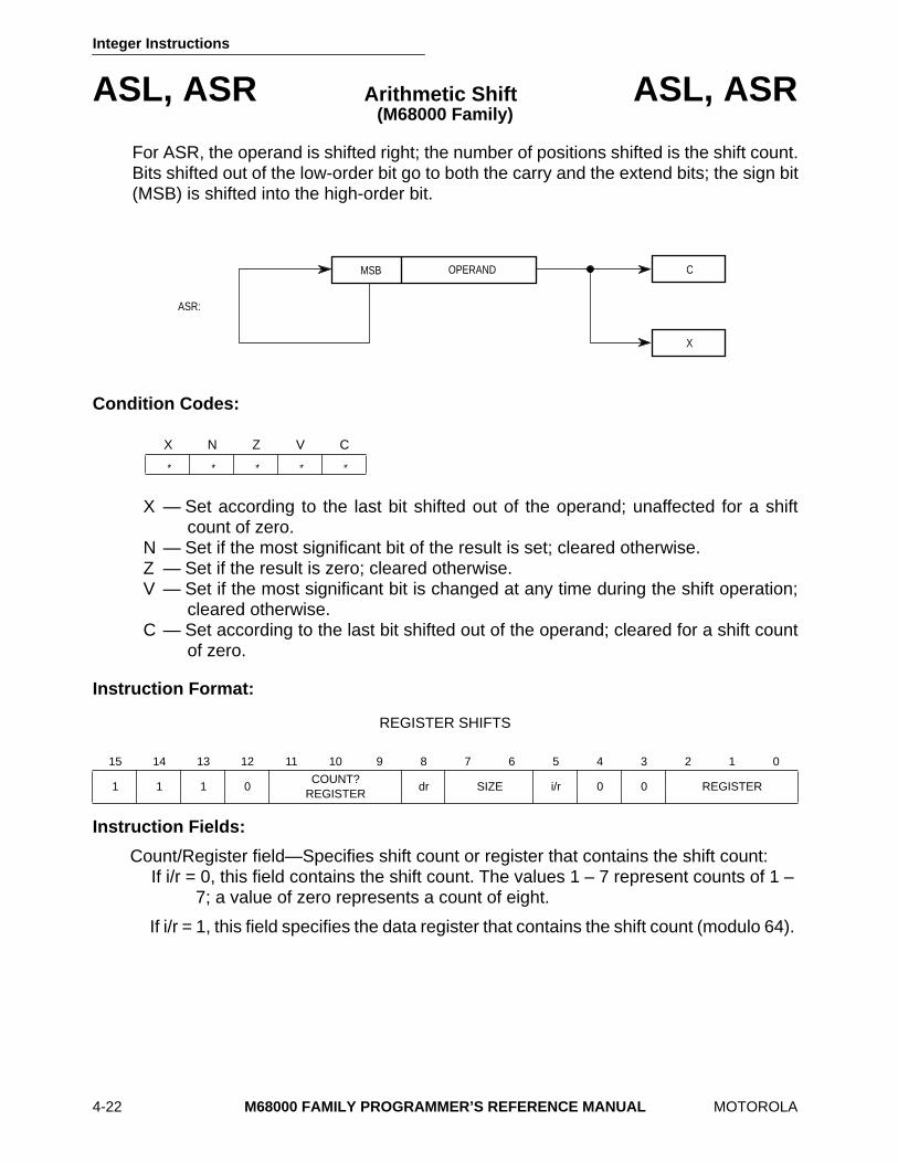
Integer Instructions
4-22 M68000 FAMILY PROGRAMMER’S REFERENCE MANUAL MOTOROLA
ASL, ASR Arithmetic Shift ASL, ASR(M68000 Family)
For ASR, the operand is shifted right; the number of positions shifted is the shift count.Bits shifted out of the low-order bit go to both the carry and the extend bits; the sign bit(MSB) is shifted into the high-order bit.
Condition Codes:
X — Set according to the last bit shifted out of the operand; unaffected for a shiftcount of zero.
N — Set if the most significant bit of the result is set; cleared otherwise. Z — Set if the result is zero; cleared otherwise. V — Set if the most significant bit is changed at any time during the shift operation;
cleared otherwise. C — Set according to the last bit shifted out of the operand; cleared for a shift count
of zero.
Instruction Format:
REGISTER SHIFTS
Instruction Fields:
Count/Register field—Specifies shift count or register that contains the shift count: If i/r = 0, this field contains the shift count. The values 1 – 7 represent counts of 1 –
7; a value of zero represents a count of eight.
If i/r = 1, this field specifies the data register that contains the shift count (modulo 64).
X N Z V C
* * * * *
15 14 13 12 11 10 9 8 7 6 5 4 3 2 1 0
1 1 1 0COUNT?
REGISTERdr SIZE i/r 0 0 REGISTER
OPERAND C
X
ASR:
MSB
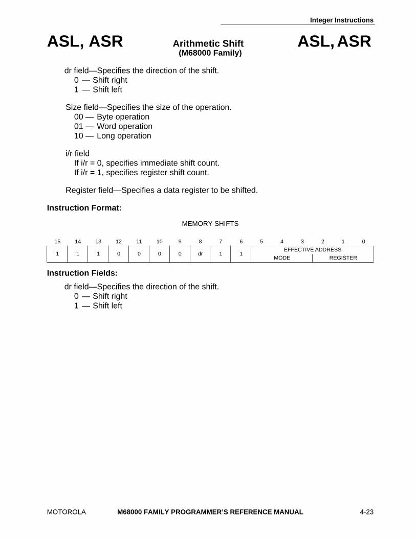
Integer Instructions
MOTOROLA M68000 FAMILY PROGRAMMER’S REFERENCE MANUAL 4-23
ASL, ASR Arithmetic Shift ASL, ASR (M68000 Family)
dr field—Specifies the direction of the shift. 0 — Shift right 1 — Shift left
Size field—Specifies the size of the operation. 00 — Byte operation 01 — Word operation 10 — Long operation
i/r field If i/r = 0, specifies immediate shift count. If i/r = 1, specifies register shift count.
Register field—Specifies a data register to be shifted.
Instruction Format:
MEMORY SHIFTS
Instruction Fields:
dr field—Specifies the direction of the shift. 0 — Shift right 1 — Shift left
15 14 13 12 11 10 9 8 7 6 5 4 3 2 1 0
1 1 1 0 0 0 0 dr 1 1EFFECTIVE ADDRESS
MODE REGISTER

Integer Instructions
4-24 M68000 FAMILY PROGRAMMER’S REFERENCE MANUAL MOTOROLA
ASL, ASR Arithmetic Shift ASL, ASR (M68000 Family)
Effective Address field—Specifies the operand to be shifted. Only memory alterableaddressing modes can be used as listed in the following tables:
*Can be used with CPU32.
Addressing Mode Mode Register Addressing Mode Mode Register
Dn — — (xxx).W 111 000
An — — (xxx).L 111 001
(An) 010 reg. number:An #<data> — —
(An) + 011 reg. number:An
– (An) 100 reg. number:An
(d16,An) 101 reg. number:An (d16,PC) — —
(d8,An,Xn) 110 reg. number:An (d8,PC,Xn) — —
MC68020, MC68030, and MC68040 only
(bd,An,Xn)* 110 reg. number:An (bd,PC,Xn)* — —
([bd,An,Xn],od) 110 reg. number:An ([bd,PC,Xn],od) — —
([bd,An],Xn,od) 110 reg. number:An ([bd,PC],Xn,od) — —
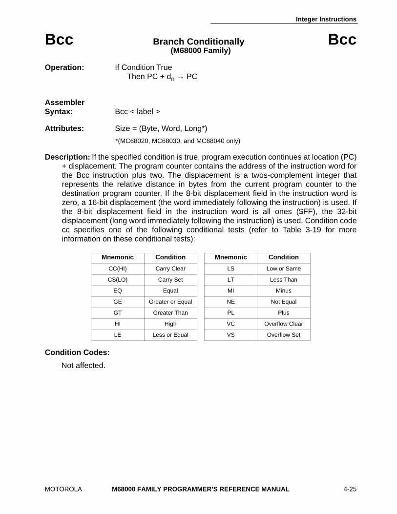
Integer Instructions
MOTOROLA M68000 FAMILY PROGRAMMER’S REFERENCE MANUAL 4-25
Bcc Branch Conditionally Bcc (M68000 Family)
Operation: If Condition True Then PC + dn → PC
Assembler Syntax: Bcc < label >
Attributes: Size = (Byte, Word, Long*)
*(MC68020, MC68030, and MC68040 only)
Description: If the specified condition is true, program execution continues at location (PC)+ displacement. The program counter contains the address of the instruction word forthe Bcc instruction plus two. The displacement is a twos-complement integer thatrepresents the relative distance in bytes from the current program counter to thedestination program counter. If the 8-bit displacement field in the instruction word iszero, a 16-bit displacement (the word immediately following the instruction) is used. Ifthe 8-bit displacement field in the instruction word is all ones ($FF), the 32-bitdisplacement (long word immediately following the instruction) is used. Condition codecc specifies one of the following conditional tests (refer to Table 3-19 for moreinformation on these conditional tests):
Condition Codes:
Not affected.
Mnemonic Condition Mnemonic Condition
CC(HI) Carry Clear LS Low or Same
CS(LO) Carry Set LT Less Than
EQ Equal MI Minus
GE Greater or Equal NE Not Equal
GT Greater Than PL Plus
HI High VC Overflow Clear
LE Less or Equal VS Overflow Set
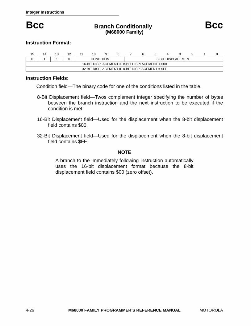
Integer Instructions
4-26 M68000 FAMILY PROGRAMMER’S REFERENCE MANUAL MOTOROLA
Bcc Branch Conditionally Bcc (M68000 Family)
Instruction Format:
Instruction Fields:
Condition field—The binary code for one of the conditions listed in the table.
8-Bit Displacement field—Twos complement integer specifying the number of bytesbetween the branch instruction and the next instruction to be executed if thecondition is met.
16-Bit Displacement field—Used for the displacement when the 8-bit displacementfield contains $00.
32-Bit Displacement field—Used for the displacement when the 8-bit displacementfield contains $FF.
NOTE
A branch to the immediately following instruction automaticallyuses the 16-bit displacement format because the 8-bitdisplacement field contains $00 (zero offset).
15 14 13 12 11 10 9 8 7 6 5 4 3 2 1 0
0 1 1 0 CONDITION 8-BIT DISPLACEMENT
16-BIT DISPLACEMENT IF 8-BIT DISPLACEMENT = $00
32-BIT DISPLACEMENT IF 8-BIT DISPLACEMENT = $FF
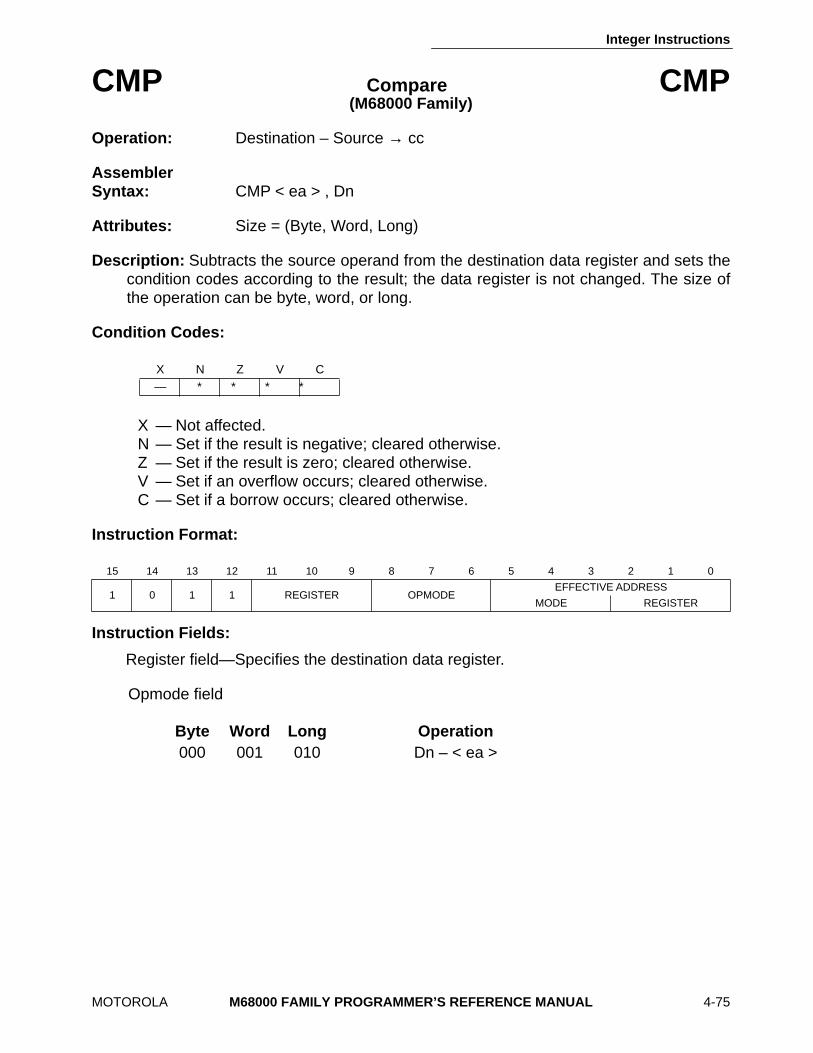
Integer Instructions
MOTOROLA M68000 FAMILY PROGRAMMER’S REFERENCE MANUAL 4-75
CMP Compare CMP (M68000 Family)
Operation: Destination – Source → cc
Assembler Syntax: CMP < ea > , Dn
Attributes: Size = (Byte, Word, Long)
Description: Subtracts the source operand from the destination data register and sets thecondition codes according to the result; the data register is not changed. The size ofthe operation can be byte, word, or long.
Condition Codes:
X — Not affected. N — Set if the result is negative; cleared otherwise. Z — Set if the result is zero; cleared otherwise. V — Set if an overflow occurs; cleared otherwise. C — Set if a borrow occurs; cleared otherwise.
Instruction Format:
Instruction Fields:
Register field—Specifies the destination data register.
Opmode field
X N Z V C — ∗ ∗ ∗ ∗
15 14 13 12 11 10 9 8 7 6 5 4 3 2 1 0
1 0 1 1 REGISTER OPMODEEFFECTIVE ADDRESS
MODE REGISTER
Byte Word Long Operation 000 001 010 Dn – < ea >
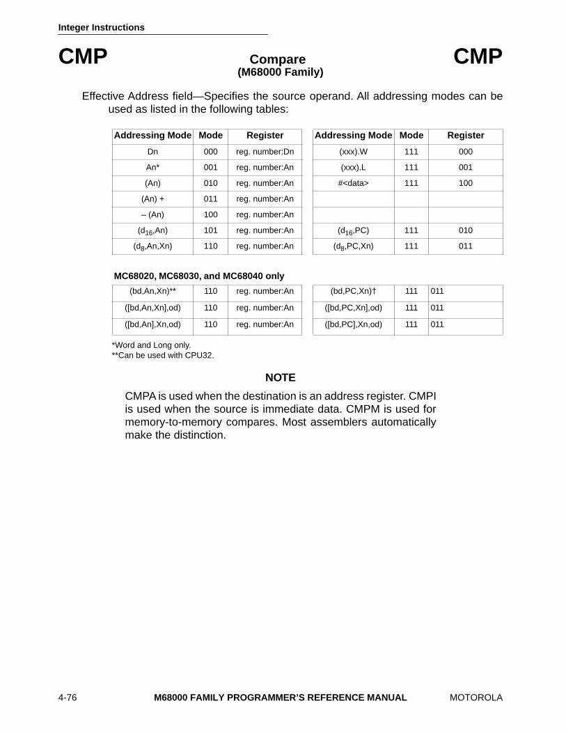
Integer Instructions
4-76 M68000 FAMILY PROGRAMMER’S REFERENCE MANUAL MOTOROLA
CMP Compare CMP (M68000 Family)
Effective Address field—Specifies the source operand. All addressing modes can beused as listed in the following tables:
*Word and Long only.**Can be used with CPU32.
NOTE
CMPA is used when the destination is an address register. CMPIis used when the source is immediate data. CMPM is used formemory-to-memory compares. Most assemblers automaticallymake the distinction.
Addressing Mode Mode Register Addressing Mode Mode Register
Dn 000 reg. number:Dn (xxx).W 111 000
An* 001 reg. number:An (xxx).L 111 001
(An) 010 reg. number:An #<data> 111 100
(An) + 011 reg. number:An
– (An) 100 reg. number:An
(d16,An) 101 reg. number:An (d16,PC) 111 010
(d8,An,Xn) 110 reg. number:An (d8,PC,Xn) 111 011
MC68020, MC68030, and MC68040 only
(bd,An,Xn)** 110 reg. number:An (bd,PC,Xn)† 111 011
([bd,An,Xn],od) 110 reg. number:An ([bd,PC,Xn],od) 111 011
([bd,An],Xn,od) 110 reg. number:An ([bd,PC],Xn,od) 111 011
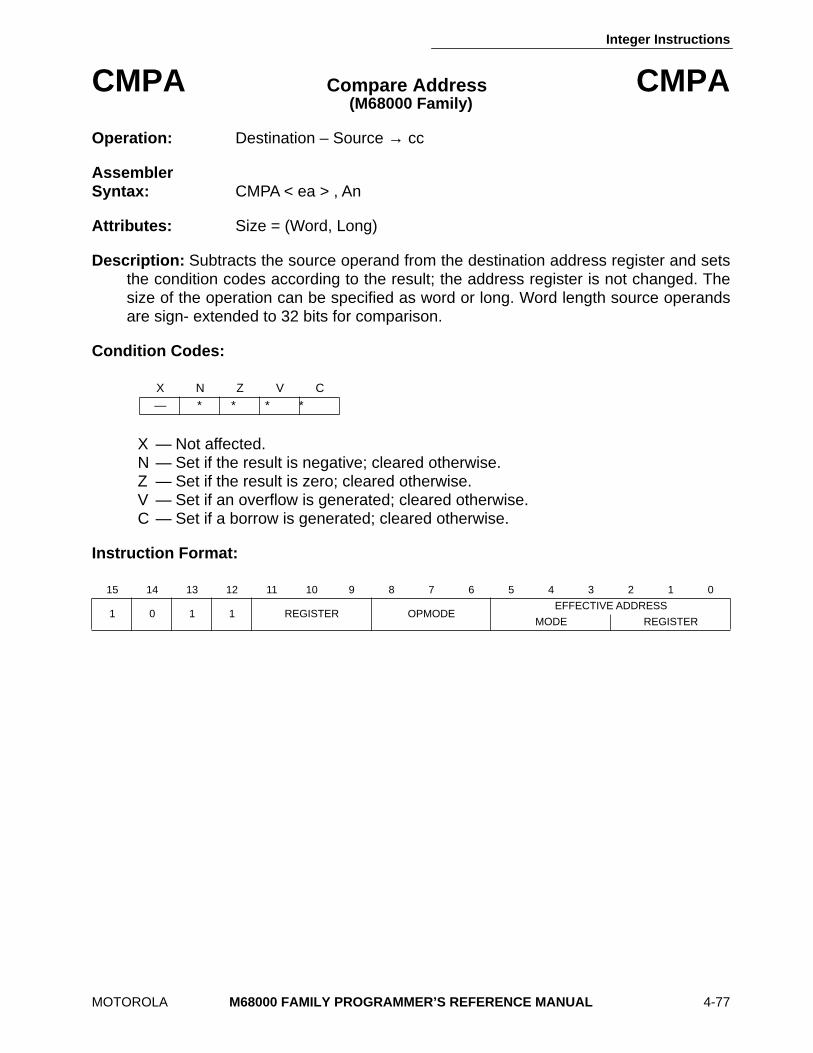
Integer Instructions
MOTOROLA M68000 FAMILY PROGRAMMER’S REFERENCE MANUAL 4-77
CMPA Compare Address CMPA (M68000 Family)
Operation: Destination – Source → cc
Assembler Syntax: CMPA < ea > , An
Attributes: Size = (Word, Long)
Description: Subtracts the source operand from the destination address register and setsthe condition codes according to the result; the address register is not changed. Thesize of the operation can be specified as word or long. Word length source operandsare sign- extended to 32 bits for comparison.
Condition Codes:
X — Not affected. N — Set if the result is negative; cleared otherwise. Z — Set if the result is zero; cleared otherwise. V — Set if an overflow is generated; cleared otherwise. C — Set if a borrow is generated; cleared otherwise.
Instruction Format:
X N Z V C — ∗ ∗ ∗ ∗
15 14 13 12 11 10 9 8 7 6 5 4 3 2 1 0
1 0 1 1 REGISTER OPMODEEFFECTIVE ADDRESS
MODE REGISTER
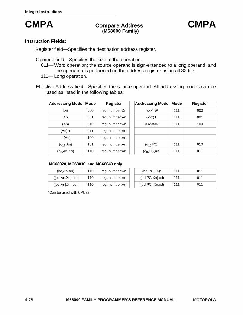
Integer Instructions
4-78 M68000 FAMILY PROGRAMMER’S REFERENCE MANUAL MOTOROLA
CMPA Compare Address CMPA (M68000 Family)
Instruction Fields:
Register field—Specifies the destination address register.
Opmode field—Specifies the size of the operation. 011— Word operation; the source operand is sign-extended to a long operand, and
the operation is performed on the address register using all 32 bits. 111— Long operation.
Effective Address field—Specifies the source operand. All addressing modes can beused as listed in the following tables:
*Can be used with CPU32.
Addressing Mode Mode Register Addressing Mode Mode Register
Dn 000 reg. number:Dn (xxx).W 111 000
An 001 reg. number:An (xxx).L 111 001
(An) 010 reg. number:An #<data> 111 100
(An) + 011 reg. number:An
– (An) 100 reg. number:An
(d16,An) 101 reg. number:An (d16,PC) 111 010
(d8,An,Xn) 110 reg. number:An (d8,PC,Xn) 111 011
MC68020, MC68030, and MC68040 only
(bd,An,Xn) 110 reg. number:An (bd,PC,Xn)* 111 011
([bd,An,Xn],od) 110 reg. number:An ([bd,PC,Xn],od) 111 011
([bd,An],Xn,od) 110 reg. number:An ([bd,PC],Xn,od) 111 011

Integer Instructions
MOTOROLA M68000 FAMILY PROGRAMMER’S REFERENCE MANUAL 4-79
CMPI Compare Immediate CMPI (M68000 Family)
Operation: Destination – Immediate Data → cc
Assembler Syntax: CMPI # < data > , < ea >
Attributes: Size = (Byte, Word, Long)
Description: Subtracts the immediate data from the destination operand and sets thecondition codes according to the result; the destination location is not changed. Thesize of the operation may be specified as byte, word, or long. The size of the immediatedata matches the operation size.
Condition Codes:
X — Not affected. N — Set if the result is negative; cleared otherwise. Z — Set if the result is zero; cleared otherwise. V — Set if an overflow occurs; cleared otherwise. C — Set if a borrow occurs; cleared otherwise.
Instruction Format:
X N Z V C — ∗ ∗ ∗ ∗
15 14 13 12 11 10 9 8 7 6 5 4 3 2 1 0
0 0 0 0 1 1 0 0 SIZEEFFECTIVE ADDRESS
MODE REGISTER
16-BIT WORD DATA 8-BIT BYTE DATA
32-BIT LONG DATA
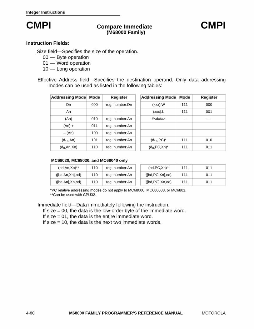
Integer Instructions
4-80 M68000 FAMILY PROGRAMMER’S REFERENCE MANUAL MOTOROLA
CMPI Compare Immediate CMPI (M68000 Family)
Instruction Fields:
Size field—Specifies the size of the operation. 00 — Byte operation 01 — Word operation 10 — Long operation
Effective Address field—Specifies the destination operand. Only data addressingmodes can be used as listed in the following tables:
*PC relative addressing modes do not apply to MC68000, MC680008, or MC6801.**Can be used with CPU32.
Immediate field—Data immediately following the instruction. If size = 00, the data is the low-order byte of the immediate word. If size = 01, the data is the entire immediate word. If size = 10, the data is the next two immediate words.
Addressing Mode Mode Register Addressing Mode Mode Register
Dn 000 reg. number:Dn (xxx).W 111 000
An — — (xxx).L 111 001
(An) 010 reg. number:An #<data> — —
(An) + 011 reg. number:An
– (An) 100 reg. number:An
(d16,An) 101 reg. number:An (d16,PC)* 111 010
(d8,An,Xn) 110 reg. number:An (d8,PC,Xn)* 111 011
MC68020, MC68030, and MC68040 only
(bd,An,Xn)** 110 reg. number:An (bd,PC,Xn)† 111 011
([bd,An,Xn],od) 110 reg. number:An ([bd,PC,Xn],od) 111 011
([bd,An],Xn,od) 110 reg. number:An ([bd,PC],Xn,od) 111 011
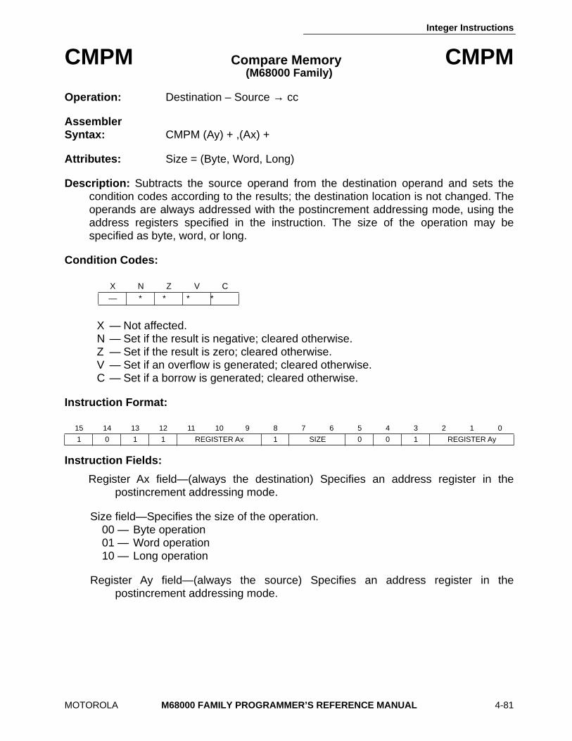
Integer Instructions
MOTOROLA M68000 FAMILY PROGRAMMER’S REFERENCE MANUAL 4-81
CMPM Compare Memory CMPM (M68000 Family)
Operation: Destination – Source → cc
Assembler Syntax: CMPM (Ay) + ,(Ax) +
Attributes: Size = (Byte, Word, Long)
Description: Subtracts the source operand from the destination operand and sets thecondition codes according to the results; the destination location is not changed. Theoperands are always addressed with the postincrement addressing mode, using theaddress registers specified in the instruction. The size of the operation may bespecified as byte, word, or long.
Condition Codes:
X — Not affected. N — Set if the result is negative; cleared otherwise. Z — Set if the result is zero; cleared otherwise. V — Set if an overflow is generated; cleared otherwise. C — Set if a borrow is generated; cleared otherwise.
Instruction Format:
Instruction Fields:
Register Ax field—(always the destination) Specifies an address register in thepostincrement addressing mode.
Size field—Specifies the size of the operation. 00 — Byte operation 01 — Word operation 10 — Long operation
Register Ay field—(always the source) Specifies an address register in thepostincrement addressing mode.
X N Z V C — ∗ ∗ ∗ ∗
15 14 13 12 11 10 9 8 7 6 5 4 3 2 1 0
1 0 1 1 REGISTER Ax 1 SIZE 0 0 1 REGISTER Ay
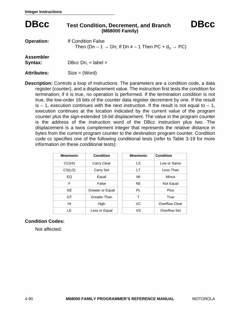
Integer Instructions
4-90 M68000 FAMILY PROGRAMMER’S REFERENCE MANUAL MOTOROLA
DBcc Test Condition, Decrement, and Branch DBcc (M68000 Family)
Operation: If Condition False Then (Dn – 1 → Dn; If Dn ≠ – 1 Then PC + dn → PC)
Assembler Syntax: DBcc Dn, < label >
Attributes: Size = (Word)
Description: Controls a loop of instructions. The parameters are a condition code, a dataregister (counter), and a displacement value. The instruction first tests the condition fortermination; if it is true, no operation is performed. If the termination condition is nottrue, the low-order 16 bits of the counter data register decrement by one. If the resultis – 1, execution continues with the next instruction. If the result is not equal to – 1,execution continues at the location indicated by the current value of the programcounter plus the sign-extended 16-bit displacement. The value in the program counteris the address of the instruction word of the DBcc instruction plus two. Thedisplacement is a twos complement integer that represents the relative distance inbytes from the current program counter to the destination program counter. Conditioncode cc specifies one of the following conditional tests (refer to Table 3-19 for moreinformation on these conditional tests):
Condition Codes:
Not affected.
Mnemonic Condition Mnemonic Condition
CC(HI) Carry Clear LS Low or Same
CS(LO) Carry Set LT Less Than
EQ Equal MI Minus
F False NE Not Equal
GE Greater or Equal PL Plus
GT Greater Than T True
HI High VC Overflow Clear
LE Less or Equal VS Overflow Set
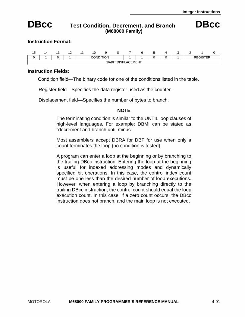
Integer Instructions
MOTOROLA M68000 FAMILY PROGRAMMER’S REFERENCE MANUAL 4-91
DBcc Test Condition, Decrement, and Branch DBcc (M68000 Family)
Instruction Format:
Instruction Fields:
Condition field—The binary code for one of the conditions listed in the table.
Register field—Specifies the data register used as the counter.
Displacement field—Specifies the number of bytes to branch.
NOTE
The terminating condition is similar to the UNTIL loop clauses ofhigh-level languages. For example: DBMI can be stated as"decrement and branch until minus".
Most assemblers accept DBRA for DBF for use when only acount terminates the loop (no condition is tested).
A program can enter a loop at the beginning or by branching tothe trailing DBcc instruction. Entering the loop at the beginningis useful for indexed addressing modes and dynamicallyspecified bit operations. In this case, the control index countmust be one less than the desired number of loop executions.However, when entering a loop by branching directly to thetrailing DBcc instruction, the control count should equal the loopexecution count. In this case, if a zero count occurs, the DBccinstruction does not branch, and the main loop is not executed.
15 14 13 12 11 10 9 8 7 6 5 4 3 2 1 0
0 1 0 1 CONDITION 1 1 0 0 1 REGISTER
16-BIT DISPLACEMENT
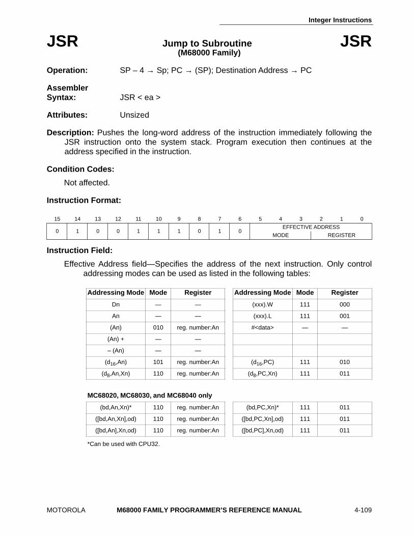
Integer Instructions
MOTOROLA M68000 FAMILY PROGRAMMER’S REFERENCE MANUAL 4-109
JSR Jump to Subroutine JSR (M68000 Family)
Operation: SP – 4 → Sp; PC → (SP); Destination Address → PC
Assembler Syntax: JSR < ea >
Attributes: Unsized
Description: Pushes the long-word address of the instruction immediately following theJSR instruction onto the system stack. Program execution then continues at theaddress specified in the instruction.
Condition Codes:
Not affected.
Instruction Format:
Instruction Field:
Effective Address field—Specifies the address of the next instruction. Only controladdressing modes can be used as listed in the following tables:
*Can be used with CPU32.
15 14 13 12 11 10 9 8 7 6 5 4 3 2 1 0
0 1 0 0 1 1 1 0 1 0EFFECTIVE ADDRESS
MODE REGISTER
Addressing Mode Mode Register Addressing Mode Mode Register
Dn — — (xxx).W 111 000
An — — (xxx).L 111 001
(An) 010 reg. number:An #<data> — —
(An) + — —
– (An) — —
(d16,An) 101 reg. number:An (d16,PC) 111 010
(d8,An,Xn) 110 reg. number:An (d8,PC,Xn) 111 011
MC68020, MC68030, and MC68040 only
(bd,An,Xn)* 110 reg. number:An (bd,PC,Xn)* 111 011
([bd,An,Xn],od) 110 reg. number:An ([bd,PC,Xn],od) 111 011
([bd,An],Xn,od) 110 reg. number:An ([bd,PC],Xn,od) 111 011
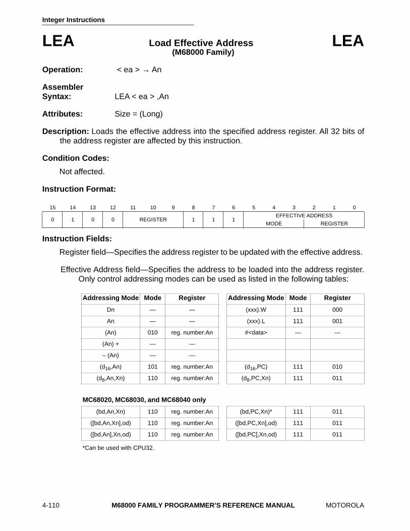
Integer Instructions
4-110 M68000 FAMILY PROGRAMMER’S REFERENCE MANUAL MOTOROLA
LEA Load Effective Address LEA (M68000 Family)
Operation: < ea > → An
Assembler Syntax: LEA < ea > ,An
Attributes: Size = (Long)
Description: Loads the effective address into the specified address register. All 32 bits ofthe address register are affected by this instruction.
Condition Codes:
Not affected.
Instruction Format:
Instruction Fields:
Register field—Specifies the address register to be updated with the effective address.
Effective Address field—Specifies the address to be loaded into the address register.Only control addressing modes can be used as listed in the following tables:
*Can be used with CPU32.
15 14 13 12 11 10 9 8 7 6 5 4 3 2 1 0
0 1 0 0 REGISTER 1 1 1EFFECTIVE ADDRESS
MODE REGISTER
Addressing Mode Mode Register Addressing Mode Mode Register
Dn — — (xxx).W 111 000
An — — (xxx).L 111 001
(An) 010 reg. number:An #<data> — —
(An) + — —
– (An) — —
(d16,An) 101 reg. number:An (d16,PC) 111 010
(d8,An,Xn) 110 reg. number:An (d8,PC,Xn) 111 011
MC68020, MC68030, and MC68040 only
(bd,An,Xn) 110 reg. number:An (bd,PC,Xn)* 111 011
([bd,An,Xn],od) 110 reg. number:An ([bd,PC,Xn],od) 111 011
([bd,An],Xn,od) 110 reg. number:An ([bd,PC],Xn,od) 111 011
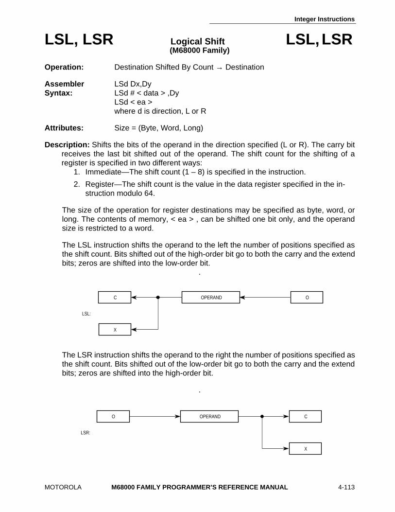
Integer Instructions
MOTOROLA M68000 FAMILY PROGRAMMER’S REFERENCE MANUAL 4-113
LSL, LSR Logical Shift LSL, LSR (M68000 Family)
Operation: Destination Shifted By Count → Destination
Assembler LSd Dx,Dy Syntax: LSd # < data > ,Dy
LSd < ea > where d is direction, L or R
Attributes: Size = (Byte, Word, Long)
Description: Shifts the bits of the operand in the direction specified (L or R). The carry bitreceives the last bit shifted out of the operand. The shift count for the shifting of aregister is specified in two different ways:
1. Immediate—The shift count (1 – 8) is specified in the instruction.
2. Register—The shift count is the value in the data register specified in the in-struction modulo 64.
The size of the operation for register destinations may be specified as byte, word, orlong. The contents of memory, < ea > , can be shifted one bit only, and the operandsize is restricted to a word.
The LSL instruction shifts the operand to the left the number of positions specified asthe shift count. Bits shifted out of the high-order bit go to both the carry and the extendbits; zeros are shifted into the low-order bit.
.
The LSR instruction shifts the operand to the right the number of positions specified asthe shift count. Bits shifted out of the low-order bit go to both the carry and the extendbits; zeros are shifted into the high-order bit.
.
C OPERAND O
X
LSL:
O OPERAND C
X
LSR:
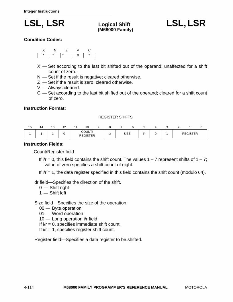
Integer Instructions
4-114 M68000 FAMILY PROGRAMMER’S REFERENCE MANUAL MOTOROLA
LSL, LSR Logical Shift LSL, LSR (M68000 Family)
Condition Codes:
X — Set according to the last bit shifted out of the operand; unaffected for a shiftcount of zero.
N — Set if the result is negative; cleared otherwise. Z — Set if the result is zero; cleared otherwise. V — Always cleared. C — Set according to the last bit shifted out of the operand; cleared for a shift count
of zero.
Instruction Format:
REGISTER SHIFTS
Instruction Fields:
Count/Register field
If i/r = 0, this field contains the shift count. The values 1 – 7 represent shifts of 1 – 7;value of zero specifies a shift count of eight.
If i/r = 1, the data register specified in this field contains the shift count (modulo 64).
dr field—Specifies the direction of the shift. 0 — Shift right 1 — Shift left
Size field—Specifies the size of the operation. 00 — Byte operation 01 — Word operation 10 — Long operation i/r field If i/r = 0, specifies immediate shift count. If i/r = 1, specifies register shift count.
Register field—Specifies a data register to be shifted.
X N Z V C ∗ ∗ ∗ 0 ∗
15 14 13 12 11 10 9 8 7 6 5 4 3 2 1 0
1 1 1 0COUNT/
REGISTERdr SIZE i/r 0 1 REGISTER
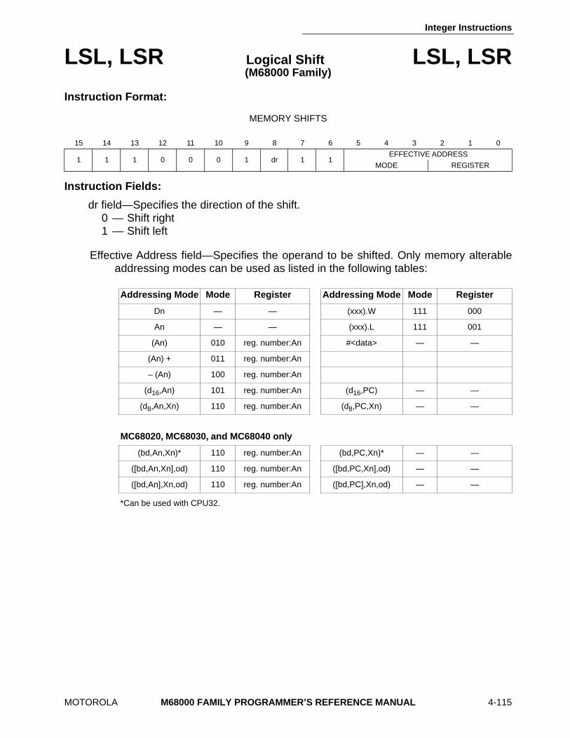
Integer Instructions
MOTOROLA M68000 FAMILY PROGRAMMER’S REFERENCE MANUAL 4-115
LSL, LSR Logical Shift LSL, LSR(M68000 Family)
Instruction Format:
MEMORY SHIFTS
Instruction Fields:
dr field—Specifies the direction of the shift. 0 — Shift right 1 — Shift left
Effective Address field—Specifies the operand to be shifted. Only memory alterableaddressing modes can be used as listed in the following tables:
*Can be used with CPU32.
15 14 13 12 11 10 9 8 7 6 5 4 3 2 1 0
1 1 1 0 0 0 1 dr 1 1EFFECTIVE ADDRESS
MODE REGISTER
Addressing Mode Mode Register Addressing Mode Mode Register
Dn — — (xxx).W 111 000
An — — (xxx).L 111 001
(An) 010 reg. number:An #<data> — —
(An) + 011 reg. number:An
– (An) 100 reg. number:An
(d16,An) 101 reg. number:An (d16,PC) — —
(d8,An,Xn) 110 reg. number:An (d8,PC,Xn) — —
MC68020, MC68030, and MC68040 only
(bd,An,Xn)* 110 reg. number:An (bd,PC,Xn)* — —
([bd,An,Xn],od) 110 reg. number:An ([bd,PC,Xn],od) — —
([bd,An],Xn,od) 110 reg. number:An ([bd,PC],Xn,od) — —
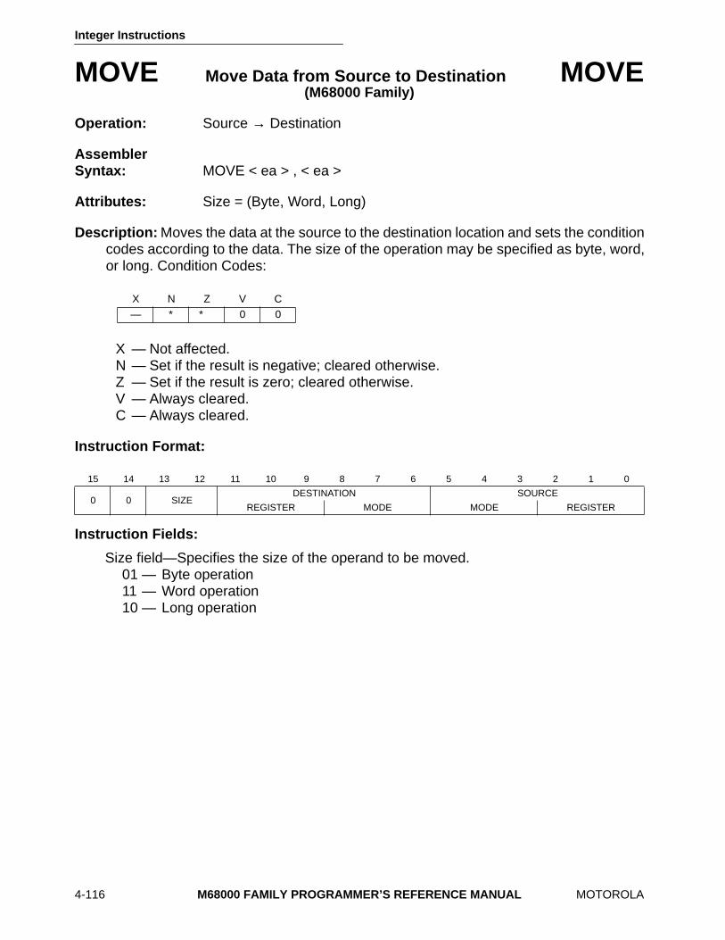
Integer Instructions
4-116 M68000 FAMILY PROGRAMMER’S REFERENCE MANUAL MOTOROLA
MOVE Move Data from Source to Destination MOVE (M68000 Family)
Operation: Source → Destination
Assembler Syntax: MOVE < ea > , < ea >
Attributes: Size = (Byte, Word, Long)
Description: Moves the data at the source to the destination location and sets the conditioncodes according to the data. The size of the operation may be specified as byte, word,or long. Condition Codes:
X — Not affected. N — Set if the result is negative; cleared otherwise. Z — Set if the result is zero; cleared otherwise. V — Always cleared. C — Always cleared.
Instruction Format:
Instruction Fields:
Size field—Specifies the size of the operand to be moved. 01 — Byte operation 11 — Word operation 10 — Long operation
X N Z V C — ∗ ∗ 0 0
15 14 13 12 11 10 9 8 7 6 5 4 3 2 1 0
0 0 SIZEDESTINATION SOURCE
REGISTER MODE MODE REGISTER
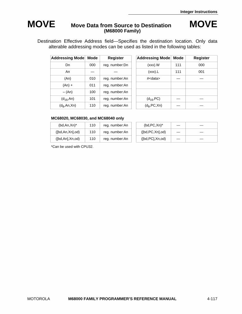
Integer Instructions
MOTOROLA M68000 FAMILY PROGRAMMER’S REFERENCE MANUAL 4-117
MOVE Move Data from Source to Destination MOVE (M68000 Family)
Destination Effective Address field—Specifies the destination location. Only dataalterable addressing modes can be used as listed in the following tables:
*Can be used with CPU32.
Addressing Mode Mode Register Addressing Mode Mode Register
Dn 000 reg. number:Dn (xxx).W 111 000
An — — (xxx).L 111 001
(An) 010 reg. number:An #<data> — —
(An) + 011 reg. number:An
– (An) 100 reg. number:An
(d16,An) 101 reg. number:An (d16,PC) — —
(d8,An,Xn) 110 reg. number:An (d8,PC,Xn) — —
MC68020, MC68030, and MC68040 only
(bd,An,Xn)* 110 reg. number:An (bd,PC,Xn)* — —
([bd,An,Xn],od) 110 reg. number:An ([bd,PC,Xn],od) — —
([bd,An],Xn,od) 110 reg. number:An ([bd,PC],Xn,od) — —
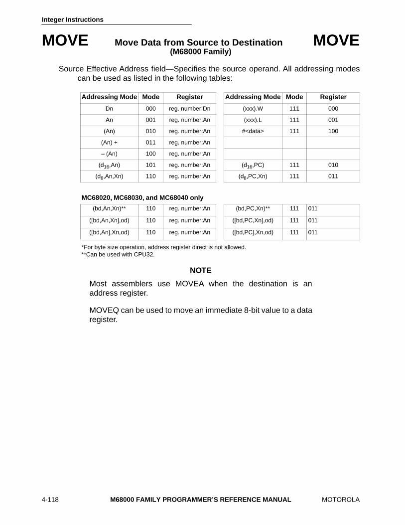
Integer Instructions
4-118 M68000 FAMILY PROGRAMMER’S REFERENCE MANUAL MOTOROLA
MOVE Move Data from Source to Destination MOVE (M68000 Family)
Source Effective Address field—Specifies the source operand. All addressing modescan be used as listed in the following tables:
*For byte size operation, address register direct is not allowed.**Can be used with CPU32.
NOTE
Most assemblers use MOVEA when the destination is anaddress register.
MOVEQ can be used to move an immediate 8-bit value to a dataregister.
Addressing Mode Mode Register Addressing Mode Mode Register
Dn 000 reg. number:Dn (xxx).W 111 000
An 001 reg. number:An (xxx).L 111 001
(An) 010 reg. number:An #<data> 111 100
(An) + 011 reg. number:An
– (An) 100 reg. number:An
(d16,An) 101 reg. number:An (d16,PC) 111 010
(d8,An,Xn) 110 reg. number:An (d8,PC,Xn) 111 011
MC68020, MC68030, and MC68040 only
(bd,An,Xn)** 110 reg. number:An (bd,PC,Xn)** 111 011
([bd,An,Xn],od) 110 reg. number:An ([bd,PC,Xn],od) 111 011
([bd,An],Xn,od) 110 reg. number:An ([bd,PC],Xn,od) 111 011

Integer Instructions
MOTOROLA M68000 FAMILY PROGRAMMER’S REFERENCE MANUAL 4-119
MOVEA Move Address MOVEA (M68000 Family)
Operation: Source → Destination
Assembler Syntax: MOVEA < ea > ,An
Attributes: Size = (Word, Long)
Description: Moves the contents of the source to the destination address register. The sizeof the operation is specified as word or long. Word-size source operands are sign-extended to 32-bit quantities.
Condition Codes:
Not affected.
Instruction Format:
Instruction Fields:
Size field—Specifies the size of the operand to be moved. 11 — Word operation; the source operand is sign-extended to a long operand and
all 32 bits are loaded into the address register. 10 — Long operation.
Destination Register field—Specifies the destination address register.
15 14 13 12 11 10 9 8 7 6 5 4 3 2 1 0
0 0 SIZEDESTINATION
REGISTER0 0 1
SOURCE
MODE REGISTER
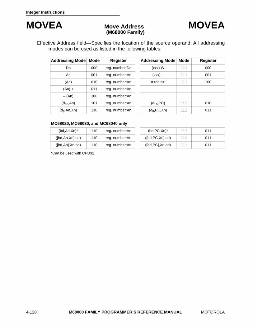
Integer Instructions
4-120 M68000 FAMILY PROGRAMMER’S REFERENCE MANUAL MOTOROLA
MOVEA Move Address MOVEA (M68000 Family)
Effective Address field—Specifies the location of the source operand. All addressingmodes can be used as listed in the following tables:
*Can be used with CPU32.
Addressing Mode Mode Register Addressing Mode Mode Register
Dn 000 reg. number:Dn (xxx).W 111 000
An 001 reg. number:An (xxx).L 111 001
(An) 010 reg. number:An #<data> 111 100
(An) + 011 reg. number:An
– (An) 100 reg. number:An
(d16,An) 101 reg. number:An (d16,PC) 111 010
(d8,An,Xn) 110 reg. number:An (d8,PC,Xn) 111 011
MC68020, MC68030, and MC68040 only
(bd,An,Xn)* 110 reg. number:An (bd,PC,Xn)* 111 011
([bd,An,Xn],od) 110 reg. number:An ([bd,PC,Xn],od) 111 011
([bd,An],Xn,od) 110 reg. number:An ([bd,PC],Xn,od) 111 011
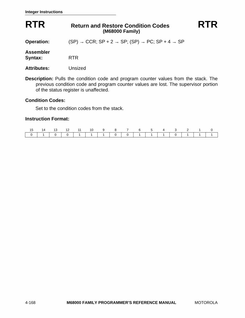
Integer Instructions
4-168 M68000 FAMILY PROGRAMMER’S REFERENCE MANUAL MOTOROLA
RTR Return and Restore Condition Codes RTR (M68000 Family)
Operation: (SP) → CCR; SP + 2 → SP; (SP) → PC; SP + 4 → SP
Assembler Syntax: RTR
Attributes: Unsized
Description: Pulls the condition code and program counter values from the stack. Theprevious condition code and program counter values are lost. The supervisor portionof the status register is unaffected.
Condition Codes:
Set to the condition codes from the stack.
Instruction Format:
15 14 13 12 11 10 9 8 7 6 5 4 3 2 1 0
0 1 0 0 1 1 1 0 0 1 1 1 0 1 1 1

Integer Instructions
MOTOROLA M68000 FAMILY PROGRAMMER’S REFERENCE MANUAL 4-169
RTS Return from Subroutine RTS (M68000 Family)
Operation: (SP) → PC; SP + 4 → SP
Assembler Syntax: RTS
Attributes: Unsized
Description: Pulls the program counter value from the stack. The previous program countervalue is lost.
Condition Codes:
Not affected.
Instruction Format:
15 14 13 12 11 10 9 8 7 6 5 4 3 2 1 0
0 1 0 0 1 1 1 0 0 1 1 1 0 1 0 1
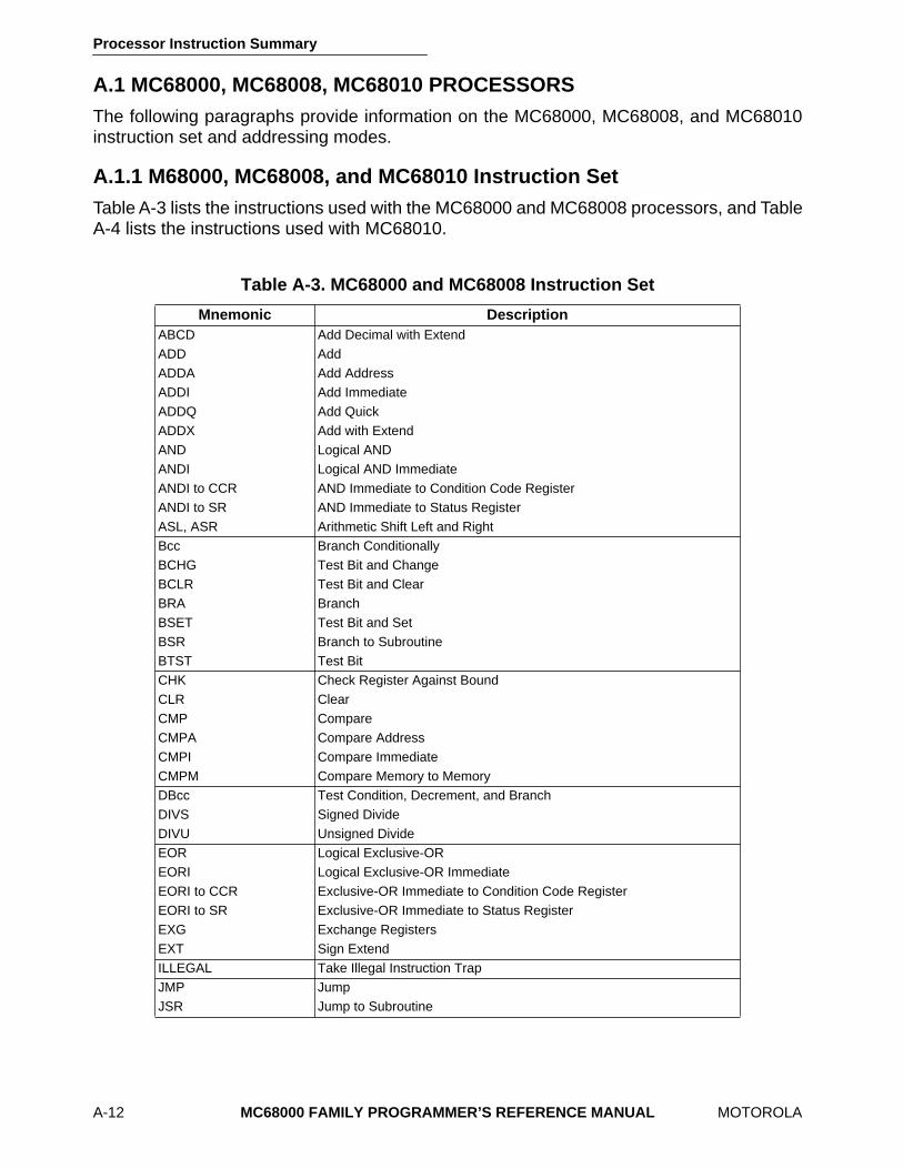
Processor Instruction Summary
A-12 MC68000 FAMILY PROGRAMMER’S REFERENCE MANUAL MOTOROLA
A.1 MC68000, MC68008, MC68010 PROCESSORS The following paragraphs provide information on the MC68000, MC68008, and MC68010instruction set and addressing modes.
A.1.1 M68000, MC68008, and MC68010 Instruction Set Table A-3 lists the instructions used with the MC68000 and MC68008 processors, and TableA-4 lists the instructions used with MC68010.
Table A-3. MC68000 and MC68008 Instruction Set
Mnemonic Description ABCD Add Decimal with Extend ADD Add ADDA Add Address ADDI Add Immediate ADDQ Add Quick ADDX Add with Extend AND Logical AND ANDI Logical AND Immediate ANDI to CCR AND Immediate to Condition Code Register ANDI to SR AND Immediate to Status Register ASL, ASR Arithmetic Shift Left and Right Bcc Branch Conditionally BCHG Test Bit and Change BCLR Test Bit and Clear BRA Branch BSET Test Bit and Set BSR Branch to Subroutine BTST Test Bit CHK Check Register Against Bound CLR Clear CMP Compare CMPA Compare Address CMPI Compare Immediate CMPM Compare Memory to Memory DBcc Test Condition, Decrement, and Branch DIVS Signed Divide DIVU Unsigned Divide EOR Logical Exclusive-OR EORI Logical Exclusive-OR Immediate EORI to CCR Exclusive-OR Immediate to Condition Code Register EORI to SR Exclusive-OR Immediate to Status Register EXG Exchange Registers EXT Sign Extend ILLEGAL Take Illegal Instruction Trap JMP Jump JSR Jump to Subroutine
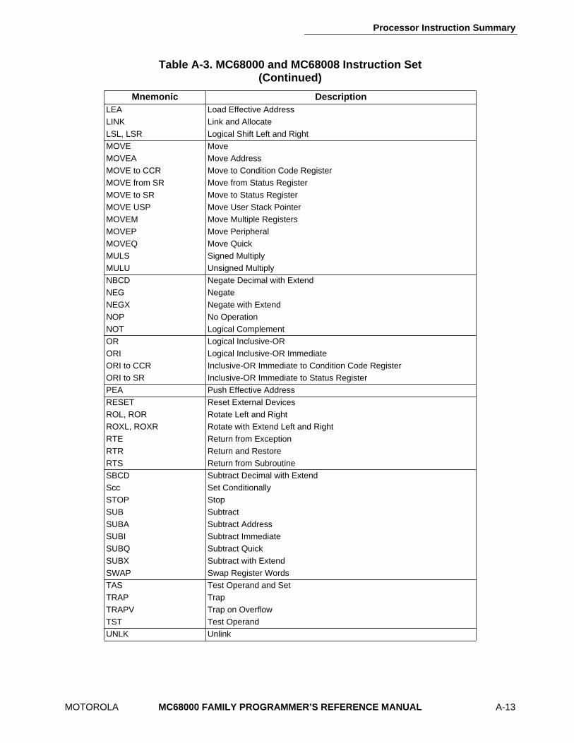
Processor Instruction Summary
MOTOROLA MC68000 FAMILY PROGRAMMER’S REFERENCE MANUAL A-13
Table A-3. MC68000 and MC68008 Instruction Set (Continued)
Mnemonic Description LEA Load Effective Address LINK Link and Allocate LSL, LSR Logical Shift Left and Right MOVE Move MOVEA Move Address MOVE to CCR Move to Condition Code Register MOVE from SR Move from Status Register MOVE to SR Move to Status Register MOVE USP Move User Stack Pointer MOVEM Move Multiple Registers MOVEP Move Peripheral MOVEQ Move Quick MULS Signed Multiply MULU Unsigned Multiply NBCD Negate Decimal with Extend NEG Negate NEGX Negate with Extend NOP No Operation NOT Logical Complement OR Logical Inclusive-OR ORI Logical Inclusive-OR Immediate ORI to CCR Inclusive-OR Immediate to Condition Code Register ORI to SR Inclusive-OR Immediate to Status Register PEA Push Effective Address RESET Reset External Devices ROL, ROR Rotate Left and Right ROXL, ROXR Rotate with Extend Left and Right RTE Return from Exception RTR Return and Restore RTS Return from Subroutine SBCD Subtract Decimal with Extend Scc Set Conditionally STOP Stop SUB Subtract SUBA Subtract Address SUBI Subtract Immediate SUBQ Subtract Quick SUBX Subtract with Extend SWAP Swap Register Words TAS Test Operand and Set TRAP Trap TRAPV Trap on Overflow TST Test Operand UNLK Unlink
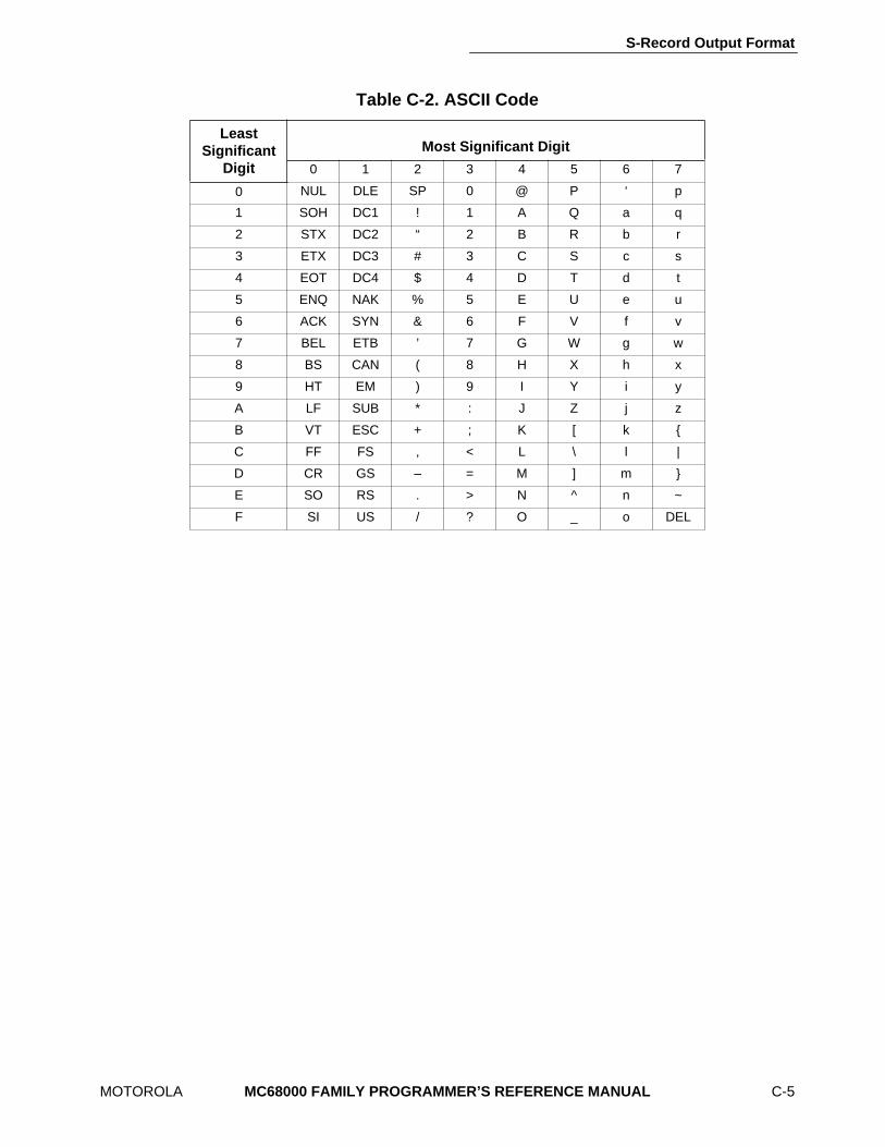
S-Record Output Format
MOTOROLA
MC68000 FAMILY PROGRAMMER’S REFERENCE MANUAL
C-5
Table C-2. ASCII Code
LeastSignificant
Digit
Most Significant Digit
0 1 2 3 4 5 6 7
0 NUL DLE SP 0 @ P ‘ p
1 SOH DC1 ! 1 A Q a q
2 STX DC2 “ 2 B R b r
3 ETX DC3 # 3 C S c s
4 EOT DC4 $ 4 D T d t
5 ENQ NAK % 5 E U e u
6 ACK SYN & 6 F V f v
7 BEL ETB ’ 7 G W g w
8 BS CAN ( 8 H X h x
9 HT EM ) 9 I Y i y
A LF SUB * : J Z j z
B VT ESC + ; K [ k {
C FF FS , < L \ l |
D CR GS – = M ] m }
E SO RS . > N ^ n ~
F SI US / ? O _ o DEL