Motorola DSP Linker/Librarian Reference Manual · MOTOROLA DSP LINKER/LIBRARIAN REFERENCE MANUAL...
96
MOTOROLA DIGITAL SIGNAL PROCESSING DEVELOPMENT SOFTWARE MOTOROLA DSP LINKER/LIBRARIAN REFERENCE MANUAL Motorola, Incorporated Semiconductor Products Sector DSP Division 6501 William Cannon Drive West Austin, TX, 78735-8598
Transcript of Motorola DSP Linker/Librarian Reference Manual · MOTOROLA DSP LINKER/LIBRARIAN REFERENCE MANUAL...
MOTOROLA DIGITAL SIGNAL PROCESSINGDEVELOPMENT SOFTWARE
MOTOROLA DSPLINKER/LIBRARIAN REFERENCE MANUAL
Motorola, IncorporatedSemiconductor Products SectorDSP Division6501 William Cannon Drive WestAustin, TX, 78735-8598
Specification and information herein are subject to change without notice. Motorola re-serves the right to make changes without further notice to any products described in thisdocument to improve reliability, function, or design. Motorola does not assume any liabilityarising out of the application or use of any product or circuit described herein, neither doesit convey any license under its patent rights or the rights of others. Motorola is a registeredtrademark of Motorola, Inc. Motorola, Inc. is an Equal Employment/Affirmative Action Em-ployer.
This manual documents the Linker and librarian as of version 6.0 of the software.
© Copyright Motorola, Inc. 1996. All rights reserved.
ASM56000, SIM56000, ASM96000, SIM96000, ASM56100, SIM56100, ASM56300,SIM56300, ASM56800, and SIM56800 are trademarks of Motorola.
MS-DOS and Windows are trademarks of Microsoft Corporation.
Sun-4 and SunOS are trademarks of Sun Microsystems, Inc.
Macintosh and MPW are trademarks of Apple Computer.

PREFACE
MOTOROLA DSP LINKER/LIBRARIAN REFERENCE MANUAL iii
Notation
The notational conventions used in this manual are:
DIRECTIVE
All linker directives and options are shown in bold upper case to highlight them.However, the linker will recognize both upper and lower case for options and direc-tives.
{ }
Contains a list of elements or directives, one of which must be selected. Eachchoice will be separated by a vertical bar. For example, {R I L} indicates that eitherR or L must be selected.
[ ]
Contains one or more optional elements. If more than one optional element isshown, the required element separators are indicated. All elements outside of theangle brackets (< >) must be specified as they appear. For example, the syntacti-cal element [<number>,] requires the comma to be specified if the optional element<number> is selected.
Preface
iv DSP LINKER/LIBRARIAN REFERENCE MANUAL MOTOROLA
Preface
< >
The element names are printed in lower case and contained in angle brackets.Some common elements used to describe linker options are:
<expr> or A linker expression<expression><number> A numeric constant<string> A string of ASCII characters enclosed in quotes<delimiter> A delimiter character<option> A linker option<sym> or A linker symbol<symbol>
Supporting Publications
DSP56000 Family Manual. Motorola, Inc. 1992.
DSP96002 User’s Manual. Motorola, Inc. 1989.
DSP56100 Family Manual. Motorola, Inc. 1993.
DSP56300 Family Manual. Motorola, Inc. 1995.
DSP56800 Family Manual. Motorola, Inc. 1996.
Motorola DSP Simulator Reference Manual. Motorola, Inc. 1996.
Motorola DSP Assembler Reference Manual. Motorola, Inc. 1996.
MOTOROLA DSP LINKER/LIBRARIAN REFERENCE MANUAL v
TABLE OF CONTENTSPREFACE
TABLE OF CONTENTS
Chapter 1MOTOROLA DSP LINKER
1.1 INTRODUCTION . . . . . . . . . . . . . . . . . . . . . . . . . . . . . . . . . . . . . . . . . . . . . 1-1
1.2 INSTALLING THE LINKER . . . . . . . . . . . . . . . . . . . . . . . . . . . . . . . . . . . . . 1-1
1.3 RUNNING THE LINKER . . . . . . . . . . . . . . . . . . . . . . . . . . . . . . . . . . . . . . . 1-1
1.4 LINKER OPTIONS . . . . . . . . . . . . . . . . . . . . . . . . . . . . . . . . . . . . . . . . . . . 1-3
Chapter 2LINKER OPERATION
2.1 INTRODUCTION . . . . . . . . . . . . . . . . . . . . . . . . . . . . . . . . . . . . . . . . . . . . . 2-1
2.2 RELOCATION AND LINKING . . . . . . . . . . . . . . . . . . . . . . . . . . . . . . . . . . . 2-1
2.3 LINKER PASSES . . . . . . . . . . . . . . . . . . . . . . . . . . . . . . . . . . . . . . . . . . . . 2-2
2.4 LINKING WITH REGIONS AND SECTIONS . . . . . . . . . . . . . . . . . . . . . . . 2-3
2.5 LINKING WITH CIRCULAR BUFFERS . . . . . . . . . . . . . . . . . . . . . . . . . . . . 2-3
2.6 LINKING WITH OVERLAYS . . . . . . . . . . . . . . . . . . . . . . . . . . . . . . . . . . . . 2-4
Chapter 3LINKER DIRECTIVES
3.1 MEMORY CONTROL FILE . . . . . . . . . . . . . . . . . . . . . . . . . . . . . . . . . . . . . 3-1
3.2 LINKER DIRECTIVE DESCRIPTIONS . . . . . . . . . . . . . . . . . . . . . . . . . . . . 3-1
3.3 MEMORY CONTROL FILE EXAMPLE . . . . . . . . . . . . . . . . . . . . . . . . . . . 3-19
Chapter 4 MOTOROLA DSP LIBRARIAN
4.1 INTRODUCTION . . . . . . . . . . . . . . . . . . . . . . . . . . . . . . . . . . . . . . . . . . . . . 4-1
4.2 INSTALLING THE LIBRARIAN . . . . . . . . . . . . . . . . . . . . . . . . . . . . . . . . . . 4-1
4.3 RUNNING THE LIBRARIAN . . . . . . . . . . . . . . . . . . . . . . . . . . . . . . . . . . . . 4-1
4.4 LIBRARIAN OPTIONS . . . . . . . . . . . . . . . . . . . . . . . . . . . . . . . . . . . . . . . . 4-2
4.5 LIBRARY PROCESSING . . . . . . . . . . . . . . . . . . . . . . . . . . . . . . . . . . . . . . 4-5
Table of Contents
vi DSP LINKER/LIBRARIAN REFERENCE MANUAL MOTOROLA
Chapter 5 MOTOROLA DSP S-RECORD CONVERSION UTILITY (SREC)
5.1 INTRODUCTION . . . . . . . . . . . . . . . . . . . . . . . . . . . . . . . . . . . . . . . . . . . . .5-1
5.2 INSTALLING SREC . . . . . . . . . . . . . . . . . . . . . . . . . . . . . . . . . . . . . . . . . . .5-1
5.3 RUNNING SREC . . . . . . . . . . . . . . . . . . . . . . . . . . . . . . . . . . . . . . . . . . . . .5-1
5.4 SREC OPTIONS . . . . . . . . . . . . . . . . . . . . . . . . . . . . . . . . . . . . . . . . . . . . .5-1
5.5 SREC PROCESSING . . . . . . . . . . . . . . . . . . . . . . . . . . . . . . . . . . . . . . . . .5-6
5.6 S-RECORD FILE FORMAT . . . . . . . . . . . . . . . . . . . . . . . . . . . . . . . . . . . . .5-8
5.6.1 S-Record Content . . . . . . . . . . . . . . . . . . . . . . . . . . . . . . . . . . . . . . . . . 5-8
5.6.2 S-Record Types. . . . . . . . . . . . . . . . . . . . . . . . . . . . . . . . . . . . . . . . . . . 5-9
5.6.2.1 S0 Record . . . . . . . . . . . . . . . . . . . . . . . . . . . . . . . . . . . . . . . . . . . . .5-9
5.6.2.2 S1, S2, S3 Records . . . . . . . . . . . . . . . . . . . . . . . . . . . . . . . . . . . . .5-10
5.6.2.3 S7, S8, S9 Records . . . . . . . . . . . . . . . . . . . . . . . . . . . . . . . . . . . . .5-10
Chapter 6 MOTOROLA DSP COFF FILE DUMP UTILITY (COFDMP)
6.1 INTRODUCTION . . . . . . . . . . . . . . . . . . . . . . . . . . . . . . . . . . . . . . . . . . . . .6-1
6.2 INSTALLING COFDMP . . . . . . . . . . . . . . . . . . . . . . . . . . . . . . . . . . . . . . . .6-1
6.3 RUNNING COFDMP . . . . . . . . . . . . . . . . . . . . . . . . . . . . . . . . . . . . . . . . . .6-1
6.4 COFDMP OPTIONS . . . . . . . . . . . . . . . . . . . . . . . . . . . . . . . . . . . . . . . . . .6-2
6.5 COFDMP PROCESSING . . . . . . . . . . . . . . . . . . . . . . . . . . . . . . . . . . . . . . .6-4
Appendix A LINKER MESSAGES
A.1 INTRODUCTION. . . . . . . . . . . . . . . . . . . . . . . . . . . . . . . . . . . . . . . . . . . . . A-1
A.2 COMMAND LINE ERRORS . . . . . . . . . . . . . . . . . . . . . . . . . . . . . . . . . . . . A-2
A.3 WARNINGS . . . . . . . . . . . . . . . . . . . . . . . . . . . . . . . . . . . . . . . . . . . . . . . . A-4
A.4 ERRORS. . . . . . . . . . . . . . . . . . . . . . . . . . . . . . . . . . . . . . . . . . . . . . . . . . . A-6
A.5 FATAL ERRORS. . . . . . . . . . . . . . . . . . . . . . . . . . . . . . . . . . . . . . . . . . . . A-15
Appendix B LIBRARIAN MESSAGES
B.1 INTRODUCTION. . . . . . . . . . . . . . . . . . . . . . . . . . . . . . . . . . . . . . . . . . . . . B-1
B.2 COMMAND LINE ERRORS . . . . . . . . . . . . . . . . . . . . . . . . . . . . . . . . . . . . B-2
B.3 WARNINGS . . . . . . . . . . . . . . . . . . . . . . . . . . . . . . . . . . . . . . . . . . . . . . . . B-3
B.4 FATAL ERRORS. . . . . . . . . . . . . . . . . . . . . . . . . . . . . . . . . . . . . . . . . . . . . B-4
Table of Contents
MOTOROLA DSP LINKER/LIBRARIAN REFERENCE MANUAL vii
Appendix CLINKER MAP FILE FORMAT
C.1 INTRODUCTION . . . . . . . . . . . . . . . . . . . . . . . . . . . . . . . . . . . . . . . . . . . . C-1
C.2 MAP FILE COMMENTARY . . . . . . . . . . . . . . . . . . . . . . . . . . . . . . . . . . . . C-1

Chapter 1MOTOROLA DSP LINKER
1.1 INTRODUCTION
The Motorola DSP Linker is a program that processes relocatable object files producedby the Motorola DSP assemblers, generating an absolute executable file which can beloaded directly into one of the Motorola DSP simulators, downloaded to an application de-velopment system, or converted to Motorola S-record format for PROM burning. A com-mand line option provides for specification of a base address for each DSP memory spaceand logical location counter. In addition, a memory control file may be supplied to indicateabsolute positioning of sections in DSP memory as well as physical mappings to internaland external memory. The Linker optionally generates a map file which shows memoryassignment of sections by memory space and a sorted list of symbols with their load timevalues.
1.2 INSTALLING THE LINKER
The Linker is distributed on various media and in different formats depending on the hostoperating system environment. See Appendix G in the Motorola DSP Assembler Ref-erence Manual , HOST-DEPENDENT INFORMATION, for details on installing and oper-ating the Linker on your particular machine.
1.3 RUNNING THE LINKER
The general format of the command line to invoke the Linker is:
DSPLNK [options] <filenames>
where:
[options]
Any of the following command line options. These can be in any order, butmust precede the list of source filenames. Some options can be given more
MOTOROLA DSP LINKER/LIBRARIAN REFERENCE MANUAL 1-1
Motorola DSP LinkerRunning the Linker
than once; the individual descriptions indicate which options may be speci-fied multiple times. Option letters can be in either upper or lower case.
Command options that are used regularly may be placed in the environmentvariable DSPLNKOPT . If the variable is found in the environment the Linkeradds the associated text to the existing command line prior to processingany options. See your host documentation for instructions on how to defineenvironment variables.
Option arguments may immediately follow the option letter or may be sepa-rated from the option letter by blanks or tabs. However, an ambiguity arisesif an option takes an optional argument. Consider the following commandline:
DSPLNK -B MAIN IO
In this example it is not clear whether the file MAIN is an input file or is meantto be an argument to the -B option. If the ambiguity is not resolved the Link-er will assume that MAIN is an input file and attempt to open it for reading.This may not be what the programmer intended.
There are several ways to avoid this ambiguity. If MAIN is supposed to bean argument to the -B option it can be placed immediately after the optionletter:
DSPLNK -B MAIN IO
If there are other options on the command line besides those that take op-tional arguments the other options can be placed between the ambiguousoption and the list of input file names:
DSPLNK -B MAIN -V IO
An alternative is to use two successive hyphens to indicate the end of theoption list:
DSPLNK -B -- MAIN IO
In this latter case the Linker interprets MAIN as an input file name and usesthe default naming conventions for the -B option.
1-2 DSP LINKER/LIBRARIAN REFERENCE MANUAL MOTOROLA
Motorola DSP LinkerLinker Options
1.4 LINKER OPTIONS
-A
Auto-align circular buffers. Any modulo or reverse-carry buffers defined inthe object file input sections are relocated independently in order to optimizeplacement in memory. Code and data surrounding the buffer is packed to fillthe space formerly occupied by the buffer and any corresponding alignmentgaps.
Example: DSPLNK -A myprog.cln
Link the file MYPROG.CLN and optimally align any buffers encoun-tered in the input.
-B[<objfil>]
This option specifies that an object file is to be created for Linker output.<objfil> can be any legal operating system filename, including an optionalpathname. A hyphen also may be used as an argument to indicate that theobject file should be sent to the standard output.
If a pathname is not specified, the file will be created in the current directory.If no filename is specified, or if the -B option is not present, the Linker willuse the basename (filename without extension) of the first filename encoun-tered in the input file list and append .CLD to the basename. If the -I optionis present (see below) an explicit filename must be given. This is becauseif the Linker followed the default action it possibly could overwrite one of theexisting input files. The -B option should be specified only once. If the filenamed in the -B option already exists, it will be overwritten.
Example: DSPLNK -B filter.cld main.cln fft.cln fio.cln
In this example, the files MAIN.CLN, FFT.CLN, and FIO.CLN arelinked together to produce the absolute executable file FILTER.CLD.
-EA <errfil>-EW <errfil>
These options allow the standard error output file to be reassigned on hoststhat do not support error output redirection from the command line. <errfil>must be present as an argument, but can be any legal operating system file-name, including an optional pathname.
The -EA option causes the standard error stream to be written to <errfil>; if<errfil> exists, the output stream is appended to the end of the file. The -EWoption also writes the standard error stream to <errfil>; if <errfil> exists it isrewound (truncated to zero), and the output stream is written from the be-
MOTOROLA DSP LINKER/LIBRARIAN REFERENCE MANUAL 1-3
Motorola DSP LinkerLinker Options
ginning of the file. Note that there must be white space separating eitheroption from the filename argument.
Example: DSPLNK -EW errors myprog.cln
Redirect the standard error output to the file ERRORS. If the file al-ready exists, it will be overwritten.
-F<argfil>
Indicates that the Linker should read command line input from <argfil>.<argfil> can be any legal operating system filename, including an optionalpathname. <argfil> is a text file containing further options, arguments, andfilenames to be passed to the Linker. The arguments in the file need be sep-arated only by some form of white space (blank, tab, newline). A semicolon(;) on a line following white space makes the rest of the line a comment.
The -F option was introduced to circumvent the problem of limited linelengths in some host system command interpreters. It may be used as oftenas desired, including within the argument file itself. Command options mayalso be supplied using the DSPLNKOPT environment variable. See the dis-cussion of DSPLNKOPT under [options] at the beginning of this section.
Example: DSPLNK -Fopts.cmd
Invoke the Linker and take command line options and input filenamesfrom the command file OPTS.CMD.
-G
Send source file line number information to the object file. The generatedline number information can be used by debuggers to provide source-leveldebugging.
Example: DSPLNK -B -G myprog.cln
Link the file MYPROG.CLN and send source file line number infor-mation to the resulting object file MYPROG.CLD.
-I
The Linker ordinarily produces an absolute executable file as output. Whenthe -I option is given the Linker combines the input files into a single relocat-able object file suitable for reprocessing by the Linker. No absolute ad-dresses are assigned and no errors are issued for unresolved externalreferences. Note that the -B option must be used when performing incre-
1-4 DSP LINKER/LIBRARIAN REFERENCE MANUAL MOTOROLA
Motorola DSP LinkerLinker Options
mental linking in order to give an explicit name to the output file. If the file-name were allowed to default it could overwrite an existing input file.
Example: DSPLNK -I -B filter.cln main.cln fft.cln fio.cln
In this example, the files MAIN.CLN, FFT.CLN, and FIO.CLN arecombined to produce the relocatable object file FILTER.CLN.
-L<library>
The Linker ordinarily processes a list of input files which each contain a sin-gle relocatable code module. If the -L option is encountered the Linkertreats the following argument as a library file and searches the file for anyoutstanding unresolved references.
If a module is found in the library that resolves an outstanding external ref-erence, the module is read from the library and included in the object file out-put. The Linker continues to search a library until all external references areresolved or no more references can be satisfied within the current library.The Linker searches a library only once, when it is encountered on the com-mand line. Therefore, the position of the -L option on the command line issignificant.
Example: DSPLNK -B filter main fir -Lio
This example illustrates linking with a library. The files MAIN.CLNand FIR.CLN are combined with any needed modules in the libraryIO.LIB to create the file FILTER.CLD.
-M[<mapfil>]
This option indicates that a map file is to be created. <mapfil> can be anylegal operating system filename, including an optional pathname. A hyphenalso may be used as an argument to indicate that the map file should besent to the standard output.
If a pathname is not specified, the file will be created in the current directory.If no filename is specified, the Linker will use the basename (filename with-out extension) of the first filename encountered in the input file list and ap-pend .MAP to the basename. If the -M option is not specified, then theLinker will not generate a map file. The -M option should be specified onlyonce. If the file named in the -M option already exists, it will be over-written.
Example: DSPLNK -M -- filter.cln gauss.cln
In this example, the files FILTER.CLN and GAUSS.CLN are linkedtogether to produce a map file. Because no filename was given withthe -M option, the output file will be named using the basename of the
MOTOROLA DSP LINKER/LIBRARIAN REFERENCE MANUAL 1-5
Motorola DSP LinkerLinker Options
first input file, in this case FILTER. The map file will be called FIL-TER.MAP.
-N
The Linker considers case significant in symbol names. When the -N optionis given the Linker ignores case in symbol names; all symbols are mappedto lower case.
Example: DSPLNK -N filter.cln fft.cln fio.cln
In this example, the files FILTER.CLN, FFT.CLN, and FIO.CLN arelinked to produce the absolute executable file FILTER.CLD. All sym-bol references are mapped to lower case.
-O<mem>[<ctr>][<map>]:<origin>
By default the Linker generates instructions and data for the output file be-ginning at absolute location zero for all DSP memory spaces. This optionallows the programmer to redefine the start address for any memory spaceand associated location counter.
<mem> is one of the single-character memory space identifiers (X, Y, L, P).The letter may be upper or lower case. The optional <ctr> is a letter indicat-ing the high (H) or low (L) location counters. If no counter is specified thedefault counter is used. <map> is also optional and signifies the desiredphysical mapping for all relocatable code in the given memory space. It maybe I for internal memory, E for external memory, R for ROM, A for port A,and B for port B. If <map> is not supplied, then no explicit mapping is pre-sumed.
The <origin> is a hexadecimal number signifying the new relocation addressfor the given memory space. The -O option may be specified as many timesas needed on the command line. This option has no effect if incrementallinking is being done (see the -I option).
Example: DSPLNK -Ope:200 myprog -Lmylib
This will initialize the default P memory counter to hex 200 and mapthe program space to external memory.
-P<pathname>
When the Linker encounters input files, the current directory (or the directorygiven in the library specification) is first searched for the file. If it is not foundand the -P option is specified, the Linker prefixes the filename (and optionalpathname) of the file specification with <pathname> and searches the newlyformed directory pathname for the file.
1-6 DSP LINKER/LIBRARIAN REFERENCE MANUAL MOTOROLA
Motorola DSP LinkerLinker Options
The pathname must be a legal operating system pathname. The -P optionmay be repeated as many times as desired. The directories will be searchedin the order specified on the command line.
Example: DSPLNK -P \project\ testprog
This example uses IBM PC pathname conventions, and would causethe Linker to prefix any library files not found in the current directorywith the \project\ pathname.
-Q
On some hosts the Linker displays a banner on the console when invoked.This option inhibits the banner display. It has no effect on hosts where thesignon banner is not displayed by default.
Example: DSPLNK -Q myprog.cln
Link the file MYPROG.CLN but do not display the signon banner onthe console.
-R[<ctlfil>]
This option indicates that a memory control file is to be read to determinethe placement of sections in DSP memory and other Linker control func-tions. <ctlfil> can be any legal operating system filename, including an op-tional pathname.
If a pathname is not specified, an attempt will be made to open the file in thecurrent directory. If no filename is specified, the Linker will use the base-name (filename without extension) of the first filename encountered in thelink input file list and append .CTL to the basename. If the -R option is notspecified, then the Linker will not use a memory control file. The -R optionshould be specified only once.
Example: DSPLNK -Rproj filter.cln gauss.cln
In this example, the files FILTER.CLN and GAUSS.CLN are linkedtogether using the memory file PROJ.CTL.
-U<symbol>
Allows the declaration of an unresolved reference from the command line.<symbol> must be specified. This option is useful for creating an undefinedexternal reference in order to force linking entirely from a library.
Example: DSPLNK -U start -Lproj.lib
Declare the symbol START undefined so that it will be resolved bycode within the library PROJ.LIB.
MOTOROLA DSP LINKER/LIBRARIAN REFERENCE MANUAL 1-7
Motorola DSP LinkerLinker Options
-V
This option causes the Linker to report linking progress (beginning of pass-es, opening and closing of input files) to the standard error output stream.This is useful to insure that link editing is proceeding normally.
Example: DSPLNK -V myprog.cln
Link the file MYPROG.CLN and send progress lines to the standarderror output.
-X<opt>[,<opt>,...,<opt>]
The -X option provides for link time options that alter the standard operationof the Linker. The options are described below (* means default). All op-tions may be preceded by NO to reverse their meaning. The -X<opt> se-quence can be repeated for as many options as desired.
Option Meaning
ABC* Perform address bounds checkingAEC* Check form of address expressionsASC Enable absolute section bounds checkingCSL Cumulate section length data
(see Chapter 3, SIZSYM Set Size Symbol)ESO Do not allocate memory below ordered sectionsOVLP Warn on section overlapPSB* Preserve sign bit in twos-complement negative
operandsRO Allow region overlapRSC* Enable relative section bounds checkingSVO Preserve object file on errorsWEX Add warning count to exit status
Example: DSPLNK -XWEX filter.cln fft.cln fio.cln
Have the Linker add the warning count to the exit status so that aproject build will abort on warnings as well as errors.
1-8 DSP LINKER/LIBRARIAN REFERENCE MANUAL MOTOROLA
Motorola DSP LinkerLinker Options
-Z
The Linker strips source file line number and symbol information from theoutput file. Symbol information normally is retained for debugging purpos-es. This option has no effect if incremental linking is being done (see the -Ioption).
Example: DSPLNK -Z filter.cln fft.cln fio.cln
In this example, the files FILTER.CLN, FFT.CLN, and FIO.CLN arelinked to produce the absolute object file FILTER.CLD. The outputfile will contain no symbol or line number information.
<filenames>
A list of operating system compatible filenames (including optional path-names). If no extension is supplied for a given file, the Linker first will at-tempt to open the file using the filename as supplied. If that is not successfulthe Linker appends .CLN to the filename and attempts to open the file again.If no pathname is specified for a given file, the Linker will look for that file inthe current directory. The list of files will be processed sequentially in theorder given and all files will be used to generate the object file and map list-ing.
For more details on Linker operation in a particular machine environment see AppendixG, HOST-DEPENDENT INFORMATION, in the Motorola DSP Assembler ReferenceManual .
MOTOROLA DSP LINKER/LIBRARIAN REFERENCE MANUAL 1-9

MOTOROLA DSP LINKER/LIBRARIAN REFERENCE MANUAL 2-1
Chapter 2LINKER OPERATION
2.1 INTRODUCTION
Using a Linker allows the programmer to break up a large program into more manageablemodules which may be assembled or compiled separately. These modules can then belink edited to produce an absolute module of the complete program. If a problem arises,only the module with the problem need be edited and reassembled. Then the programmercan relink the updated relocatable object module and the other previously created objectmodules to produce a new executable file.
2.2 RELOCATION AND LINKING
The input to the Linker is a set of relocatable object modules produced by the MotorolaDSP assembler. The term relocatable means that the data in the module has not yetbeen assigned to absolute addresses in memory; instead, each different section is as-sembled as though it started at relative address 0 (an exception to this is absolute blocks,which do get assigned to absolute addresses at assembly time). When creating an abso-lute object module, it is the job of the Linker to read all the relocatable object moduleswhich comprise a program and assign the relocatable blocks in each section to an abso-lute memory address. Then in the process of actually putting the code and data read fromeach object module into the proper location in the executable file, the Linker must fill inthe correct addresses for such items as absolute addresses and references across sec-tions. This is the process of relocation.
Along with relocation, the Linker performs resolution between modules, so that one mod-ule may reference symbols defined in a different module. At assembly time the moduledoing the referencing has no idea where the symbol it is referencing will be in the finalabsolute module. Therefore, the assembler sets up information in the relocatable objectmodule which indicates that an external symbol is referenced in this module and wherethe symbol is referenced. In the relocatable object module where the symbol is definedthere is information indicating that this is the module in which the symbol is defined, alongwith the value of the symbol in the module. When the modules are presented as input tothe Linker, the correct value of the symbol can be inserted wherever it is referenced.
If an external reference is made to a symbol for which there is no corresponding record inthe input, the Linker flags it as an unresolved external reference. No final values are as-
Linker OperationLinker Passes
2-2 DSP LINKER/LIBRARIAN REFERENCE MANUAL MOTOROLA
signed to these references, and the resulting output file is unusable. A list of unresolvedreferences is sent to the Linker’s standard output and to the optional link map file.
References in the input file may be specified as either absolute or relative expressions.An absolute expression is one which consists only of absolute terms, or is the differencebetween two relative terms. A relative expression consists of one relative term along withabsolute terms and/or the result of two relative terms with opposing signs. Expressionsin the input file are a modified notation as supported by the assembler. See Appendix Ein the Motorola DSP Assembler Reference Manual for more information on the formatof relocatable object file expressions.
2.3 LINKER PASSES
The Linker makes two partial passes over the input data. During the first pass, it collectssection, symbol, and external reference information from each input file given on the com-mand line. If the input file is a library, the Linker checks to see if there are any externalreferences outstanding. If there are, the Linker opens the library file and searches eachmodule in the library until all external references are resolved or no more references canbe satisfied within that library. If there are no outstanding unresolved references, the Link-er skips the library. At the end of the first pass a list of unresolved external references issent to the standard output as well as to the map file if one exists. References to unre-solved symbols may be fixed up using the SYMBOL directive of the memory control file,discussed in Chapter 3.
Prior to the second pass, the Linker scans its internal tables and performs fixups on sec-tion start addresses and symbol values. This includes setting the base relocation addressfor any memory spaces and counters as given by the -O option on the command line orthe BASE directive in the memory control file. If a memory control file was specified onthe command line it is opened and read to determine placement of any named sectionsin memory.
Blocks of code and data are arranged in memory first by region then by location counterassignment. Absolute sections are located first, followed by ordered sections, and thenany remaining sections are placed in memory. It is possible that addresses assigned to asection using a numbered location counter might overlap addresses of another section us-ing a different counter. This design is intentional so that counters may be used as a logicalconnection to the physical mapping of separate memories (e.g. internal and externalRAM), or as a means for supporting load and runtime counters for overlays.
During the second pass, the Linker processes the data records, evaluating data fields asexpressions and writing the modified values to the output file. Errors are reported duringeither pass, and the Linker may abort depending on the severity of the error. Linker errorsare routed to standard output so they may be redirected to a file if necessary. An outputfile produced with errors should not be used in any case. The number of errors is returnedas an exit status when the Linker returns control to the host operating system.
Linker OperationLinking with Regions and Sections
MOTOROLA DSP LINKER/LIBRARIAN REFERENCE MANUAL 2-3
2.4 LINKING WITH REGIONS AND SECTIONS
The basic relocatable entity is the section . Sections are created by the assembler SEC-TION directive. A section may contain code or data from any DSP memory space, and theaddresses of the code or data may be relocatable or absolute. Sections that are not ab-solute at assembly time can be located either directly using the Linker memory control fileSECTION directive, or indirectly via the Linker command line -O option or the control fileBASE directive. Note that sections do not have to be relocatable to be linked; an absolutesection can be linked with any arbitrary module that contains or satisfies a reference tothat section.
Sections may be grouped for relocation into regions . A region is a defined area of mem-ory where sections are located. Regions make it possible to specify varying base ad-dresses for different groups of sections and set boundaries for section growth. Whereassections represent blocks of code or data which are positioned within a given memorymap, regions designate an area of a specified size where sections can be placed.
There is always at least one default region. Other regions are defined using the Linker RE-GION directive. A region always has a size and a start and end address. If these are notgiven, the Linker uses default values (e.g. if no end address is supplied for a region, thehighest target address is used).
Regions should not overlap. One exception is that regions may overlap for setting overlaybase addresses. Another exception is the default region, which allows explicit regions tosupersede it for relocation blocks. After all sections in explicit regions are located, theLinker relocates remaining sections around the previously assigned blocks within the de-fault region. This behavior can be altered with the Linker RO option (see section 1.3).
2.5 LINKING WITH CIRCULAR BUFFERS
A circular buffer is a fixed area of memory manipulated via special-purpose DSP ad-dressing modes. Because of the way buffers are accessed, they must be suitably alignedon an address boundary. When the programmer declares a modulo or reverse-carry buff-er, the assembler aligns the buffer block at an address corresponding to the size of thebuffer. The alignment may create a padding gap comprising the locations skipped to prop-erly position the buffer block in memory.
The Linker processes buffer blocks in one of two ways. By default, it keeps track of thelargest buffer in any section and aligns the entire section based on the size of the largestbuffer block. This insures that any smaller buffers contained in the section will remainaligned after relocation, but it can introduce additional padding gaps because of the sec-tion alignment.
If the -A option is given on the Linker command line, or if one of the buffer alignment di-rectives is specified in the memory control file, the Linker auto-aligns buffers. It extractsthe buffer blocks in a given section, locates them in memory before any other relocatableblocks, and repositions the section code and data to fill in gaps left from padding and re-
Linker OperationLinking with Overlays
2-4 DSP LINKER/LIBRARIAN REFERENCE MANUAL MOTOROLA
located buffers. The Linker sorts the buffers, placing the largest blocks in memory first inorder to make more eligible addresses available for subsequent smaller blocks.
Auto-alignment works only with relocatable buffers; the Linker will not attempt to realignany absolute block. Also, a buffer defined inside a relocatable overlay cannot be auto-aligned because the assumption is that the overlay block will move, invalidating any opti-mal placement of the buffer. If a buffer is declared using an open-ended alignment direc-tive such as BADDR , the Linker will not auto-align any buffers within that sectionassociated with the current memory space and counter. This is because the Linker hasno knowledge of how far the open-ended block extends, and since alignment works onlyat the section level, the Linker must abandon auto-alignment of all buffers in the section.See Chapter 4 in the Motorola DSP Assembler Reference Manual for more informationon circular buffers.
2.6 LINKING WITH OVERLAYS
An overlay is a segment of code or data that is loaded at one address, but is moved andexecuted or used at another location. A good example is a user program burned intoPROM and transferred into internal RAM by the DSP bootstrap program. The Linker han-dles overlays by recognizing overlay blocks, reconciling overlay block addresses with pre-viously relocated sections, and altering values for symbols associated with overlay blocks.
Processing of any overlays is postponed until after all absolute and otherwise relocatablesections have been placed into the memory map. This is done so that any overlays basedon an explicit address (e.g. a relocatable expression) will be properly located. If overlaysexist that were not explicitly based (default overlays), the Linker attempts to base themfrom previous explicit blocks. If there are no explicit blocks, the Linker will base the defaultoverlays from the enclosing section or region base address. In all cases for default over-lays, the blocks will be located as if they were contiguous; that is, default overlays will notoverlap one another.
After all overlay blocks are processed the Linker resolves overlay symbols. Overlay sym-bols are those labels defined inside an overlay within the source file. The overlay blockinformation is retained for reporting to the link map file. See Chapter 4 in the MotorolaDSP Assembler Reference Manual for more information on overlays.
MOTOROLA DSP LINKER/LIBRARIAN REFERENCE MANUAL 3-1
Chapter 3LINKER DIRECTIVES
3.1 MEMORY CONTROL FILE
A memory control file is simply a text file containing Linker directives. It optionally containsmodule identification, a global starting load address for linking purposes, and ordering,sizing, or placement information for any named sections. Section addresses may be forany memory space and any logical location counter. The memory control file also canspecify physical memory mappings (internal, external) associated with any memory spaceor counter. In addition, global unresolved symbols may be assigned values in the memorycontrol file.
3.2 LINKER DIRECTIVE DESCRIPTIONS
Linker directives are commands which control the operation of the Linker with respect tosection relocation, buffer alignment, symbol definition, and map file format. Linker direc-tives are listed below:
BALIGN MAP SBALIGN SIZSYMBASE MEMORY SECSIZE STARTIDENT REGION SECTION SYMBOLINCLUDE RESERVE SET
Several of the directives use the notation mem or memx to indicate the contents of a field.The definitions of mem and memx are as follows:
mem = <attr>:<exp>memx = <attr>:<exp>..<exp>attr = <scm> | <sme>scm = <spc>[<ctr>][<map>]sme = <spc>[<map>][(exp)]spc = X | Y | L | Pctr = L | Hmap = I | E | R | A | Bexp = expression
Linker DirectivesLinker Directive Descriptions
3-2 DSP LINKER/LIBRARIAN REFERENCE MANUAL MOTOROLA
The spc field indicates one of the DSP memory spaces (X, Y, L, P). The ctr field specifieseither Low or High location counters; if none is given the default counter is used. Alterna-tively, an expression in parentheses may be provided to indicate an arbitrary counter des-ignation. The map field indicates Internal memory, External memory, ROM, port A, or portB; this field may be omitted, in which case no explicit mapping is done.
Linker DirectivesLinker Directive Descriptions
MOTOROLA DSP LINKER/LIBRARIAN REFERENCE MANUAL 3-3
BALIGNAuto-align Circular Buffers
BALIGN <mem>[,...,<mem>]
The BALIGN directive auto-aligns circular buffers within a particular region. All relocat-able buffers found in any section within the region are relocated independently for optimalplacement in memory. Code and data around the buffer is made contiguous in order to fillin previously occupied space. The <mem> argument indicates where in memory the align-ment should begin.
Example:
BALIGN XE:$200,YE:$200 ; Realign X and Y external buffers
Linker DirectivesLinker Directive Descriptions
3-4 DSP LINKER/LIBRARIAN REFERENCE MANUAL MOTOROLA
BASESet Region Base Address
BASE <mem>[,...,<mem>]
The BASE directive indicates where to begin the location counter for the given memoryregion. This will be the base link address for all specified memory areas and all linkedcode and data within the region except for sections relocated absolutely via a memory fileSECTION directive. Code and data not explicitly relocated will originate from this ad-dress. The BASE directive is analogous to the Linker -O command line option.
Example:
BASE XE:$200,YE:$200,PI:$200 ; Set memory base addresses
Linker DirectivesLinker Directive Descriptions
MOTOROLA DSP LINKER/LIBRARIAN REFERENCE MANUAL 3-5
IDENTObject Module Identification
IDENT <module name> <version> <revision> [;<comment>]
The IDENT directive functions similarly to the assembler IDENT directive by identifyingthe name, version number, and revision number of the absolute or incrementally linkedoutput module. The information is sent to the resulting output file. The <module name>adheres to the rules for assembly language labels, so that it must begin with an alphabeticcharacter and consist only of alphanumeric characters or the underscore up to a length of255. The version number and revision number must be absolute expressions. If a com-ment follows the version and revision numbers it will be copied into the output file as well.
Example:
IDENT MYMODULE 1 2 ; MYMODULE, version 1, revision 2
Linker DirectivesLinker Directive Descriptions
3-6 DSP LINKER/LIBRARIAN REFERENCE MANUAL MOTOROLA
INCLUDEInclude Directive File
INCLUDE <filename>
The INCLUDE directive provides for insertion of separate files containing other Linkercontrol directives. File inclusion can be convenient for always including a set of masterdirectives in several different configuration files. <filename> must be in quotes.
Example:
INCLUDE ’main.ctl’ ; Include master control file
Linker DirectivesLinker Directive Descriptions
MOTOROLA DSP LINKER/LIBRARIAN REFERENCE MANUAL 3-7
MAP PAGEMap File Format Control
MAP PAGE <exp1>[,<exp2>[,<exp3>[,<exp4>[,<exp5>]]]]
The MAP PAGE modifier works similarly to the assembler PAGE directive, and causesthe .MAP file to be printed on the page according to the parameters supplied. If no MAPPAGE appears in the memory control file, the Linker produces a map file with a columnwidth of 80, a physical page length of 66 lines, and no blank lines at top and bottom.
Example:
MAP PAGE 132,,3,3
The above MAP PAGE directive indicates a column width of 132, a physical page lengthof 66 lines (default), with three blank lines at the top and bottom of each page.
Linker DirectivesLinker Directive Descriptions
3-8 DSP LINKER/LIBRARIAN REFERENCE MANUAL MOTOROLA
MAP OPTMap File Contents Control
MAP OPT <option>[,<option>,...,<option>]
The MAP OPT modifier determines the content of the output in the Linker map file. Thefollowing MAP OPT options are available:
GLOBMAP - produce global map by memory spaceNOCONST - do not list symbols without a memory space attributeNOGLOBSYM - omit symbols from global mapNOLOCAL - do not list non-global symbols (e.g. symbols which
are local to a section)NOSECADDR - do not list sections by addressNOSECNAME - do not list sections by nameNOSYMNAME - do not list symbols by nameNOSYMVAL - do not list symbols by valueNOUNUSED - do not list unused memory blocks
If no MAP OPT is found in the memory control file, the Linker will list all symbols and sec-tions by name, address, and value.
Example:
MAP OPT NOCONST,NOSYMVAL
The above MAP OPT directive specifies no constants in the map listing and no symbolsby value.
Linker DirectivesLinker Directive Descriptions
MOTOROLA DSP LINKER/LIBRARIAN REFERENCE MANUAL 3-9
MEMORYSet Region High Memory Address
MEMORY <mem>[,...,<mem>]
The MEMORY directive establishes a maximum high memory address for locating codeand data in the given memory region. If the Linker attempts to relocate a block beyondthe address specified in the MEMORY directive, an error will occur. This directive is use-ful for reflecting the true physical memory limits of the target system.
Example:
MEMORY PE:$1FFF ; External program memory ends at hex 1FFF
Linker DirectivesLinker Directive Descriptions
3-10 DSP LINKER/LIBRARIAN REFERENCE MANUAL MOTOROLA
REGIONEstablish Memory Region
REGION <region> [<mem>[,...,<mem>]]...
ENDR
The REGION directive defines a region of memory in which to locate sections. The regionname identifies the region. The optional <mem> parameter gives an absolute region size.The REGION directive is used in conjunction with existing control directives to specify abounds for placing sections in memory. For example, a BASE directive used within a RE-GION/ENDR pair defines the base address for that region only. Likewise a MEMORY di-rective within a REGION scope indicates the high address for the enclosing region.
Example:
REGION INTERNAL_ROM X:$256,Y:$256BASE X:0,Y:0 ; Base for INTERNAL_ROM region onlySECTION BUFFERSENDR
Linker DirectivesLinker Directive Descriptions
MOTOROLA DSP LINKER/LIBRARIAN REFERENCE MANUAL 3-11
RESERVEReserve Memory Block
RESERVE <memx>[,...,<memx>]
The RESERVE directive sets aside a block of memory which the Linker will not use forrelocation. The expression field in the <mem> parameter takes the form of a range n..m ,where n is the low reserve address and m is the high reserve address. This directive canbe used to protect ROM locations, system code, or uninitialized buffer areas.
Example:
RESERVE PI:$0..$1FF ; Protect interrupt vectors
Linker DirectivesLinker Directive Descriptions
3-12 DSP LINKER/LIBRARIAN REFERENCE MANUAL MOTOROLA
SBALIGNAuto-align Section Buffers
SBALIGN <section> <mem>[,...,<mem>]
The SBALIGN directive auto-aligns circular buffers within a named section. All relocat-able buffers found in the section are relocated independently for optimal placement inmemory. Code and data around the buffer is made contiguous in order to fill in previouslyoccupied space. The <mem> argument indicates where in memory the alignment shouldbegin.
Example:
SBALIGN MYSEC XE:$200 ; Realign X external buffers
Linker DirectivesLinker Directive Descriptions
MOTOROLA DSP LINKER/LIBRARIAN REFERENCE MANUAL 3-13
SECSIZEPad Section Length
SECSIZE <section> [<mem>[,...,<mem>]]
The SECSIZE directive provides a mechanism for padding a section to a particular lengthdespite its code or data content. The value field in the mem parameter is an expressionwhich can either be an absolute size expressed as an integer, or a floating point value rep-resenting a percentage to pad.
Example:
SECSIZE PADSEC X:$1000,Y:$1000 ; X and Y absolute sizeSECSIZE PADSEC P:150.0 ; Increase size by one half
Linker DirectivesLinker Directive Descriptions
3-14 DSP LINKER/LIBRARIAN REFERENCE MANUAL MOTOROLA
SECTIONSet Section Base Address
SECTION <section> [<mem>[,...,<mem>]]
The SECTION directive either assigns a section of code or data to an absolute location inDSP memory, or implies an ordering if no address specification is present. The addressesserve as the base for the corresponding memory spaces and counters in the named sec-tion. Any memory areas not indicated in the SECTION directive are relocated relative tothe global starting load address given by the -O command line option or the memory fileBASE directive. If there is no -O option or BASE directive, unassigned areas are placedin memory relative to location zero.
If the SECTION directive appears with only a section name and no address, it means thatthe Linker should locate this section in memory before handling any other default sec-tions. Thus given a set of sections A, B, C, and D, if B and C were listed in SECTIONdirectives without a corresponding address, the Linker would place B and C in memorybefore A and D. This provides a means for ordering sections in memory.
Example:
SECTION ABS X:$2000,Y:$2000 ; X and Y absolute baseSECTION ORD ; Ordered section
Linker DirectivesLinker Directive Descriptions
MOTOROLA DSP LINKER/LIBRARIAN REFERENCE MANUAL 3-15
SETSet Symbol Value
SET <symbol> { <mem> | <expression> }
The SET directive is a synonym for the SYMBOL directive, described below. It is usefulfor sharing counter declaration files between the assembler and Linker since the syntaxis compatible.
Example:
SET PCTR 5 ; Set P memory counter number
Linker DirectivesLinker Directive Descriptions
3-16 DSP LINKER/LIBRARIAN REFERENCE MANUAL MOTOROLA
SIZSYMSet Size Symbol
SIZSYM <symbol> <attr>:[<section>]
The SIZSYM directive makes it possible to declare an arbitrary symbol to hold sectionlength data. This is useful when the programmer needs a cumulative section length foroverlay handling. It is analogous to the SYMBOL directive, in that the symbol so definedmay be employed to resolve an external reference in a source file.
If no section name is supplied the Linker returns the length of all sections for the memoryspace and counter specified. Ordinarily the Linker retains length data only for relocatablesections; use CSL (see -X option) to cumulate length data for absolute and buffer sectionsas well. Note that SIZSYM symbols are valued after the memory control file is read, sothat attempting to reference the symbol value within the memory control file itself maycause erroneous results.
Example:
SIZSYM XLEN X: ; Assign length of X memory to XLEN
Linker DirectivesLinker Directive Descriptions
MOTOROLA DSP LINKER/LIBRARIAN REFERENCE MANUAL 3-17
STARTEstablish Start Address
START <expression>
The START directive gives an alternative start address to which the program will jump atruntime. This value is ordinarily given by the assembler END directive. The expressionmay consist of an absolute value or a global symbol whose value will be adjusted duringlink processing.
Example:
START BEGIN ; Jump to location BEGIN after loading
Linker DirectivesLinker Directive Descriptions
3-18 DSP LINKER/LIBRARIAN REFERENCE MANUAL MOTOROLA
SYMBOLSet Symbol Value
SYMBOL <symbol> { <mem> | <expression> }
The SYMBOL directive allows the programmer to specify a value for an otherwise unre-solved reference. The named symbol must not have been defined during link processing.The symbol is stored as an absolute global symbol. The symbol value may be either in-teger or floating point. If the value is an address it may contain a memory space referenceand optionally a counter and mapping designation.
Example:
SYMBOL TARGET X:$200 ; Set TARGET to hex 200
Linker DirectivesMemory Control File Example
MOTOROLA DSP LINKER/LIBRARIAN REFERENCE MANUAL 3-19
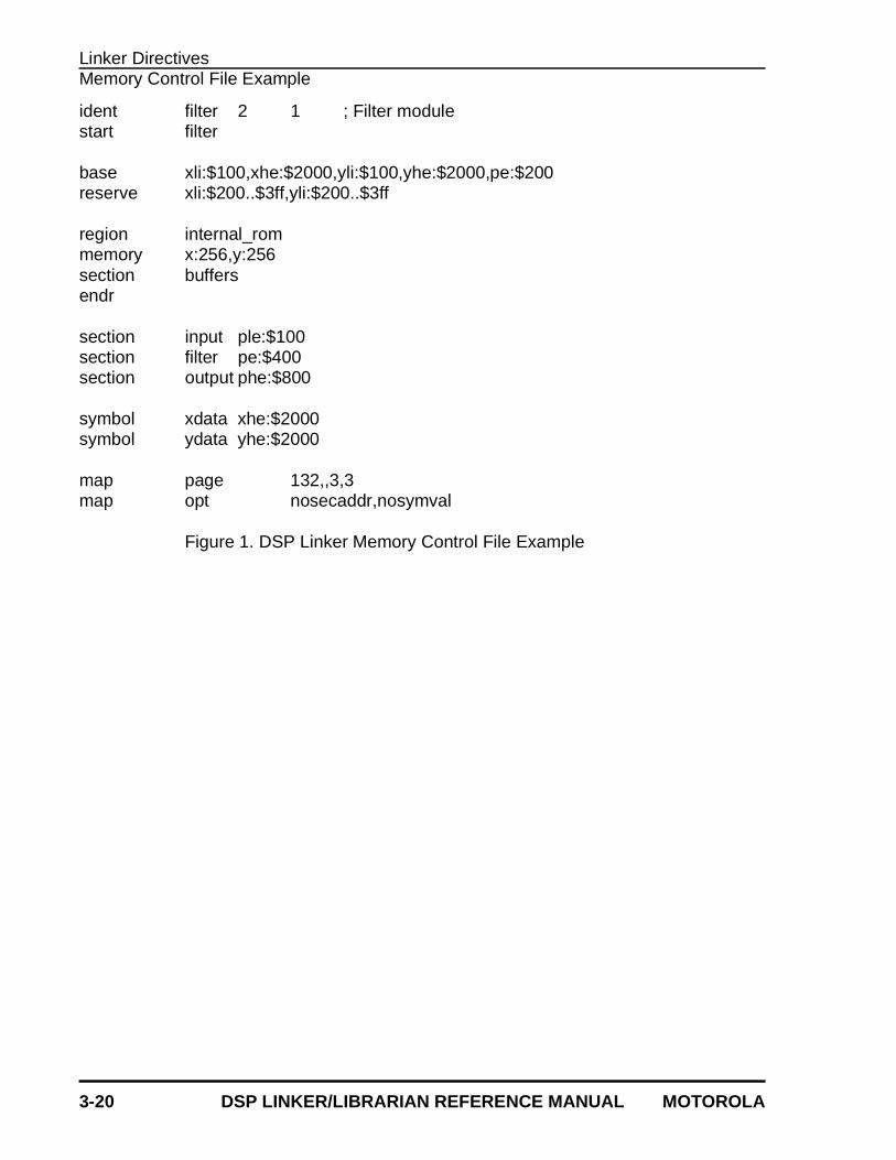
3.3 Memory Control File Example
Figure 1 shows the contents of an example memory control file. The IDENT directive iden-tifies the object module and gives it explicit version and revision numbers. The commentis also preserved in the output file. The START directive gives a starting address of FIL-TER for the program, overriding any previous settings done with the assembler END di-rective.
The BASE directive indicates that the X and Y low memory counters are to be mappedinto internal DSP memory, with a starting address of 100 hexadecimal. Any data associ-ated with the X or Y low memory counters, and not relocated due to a subsequent memoryfile SECTION directive, will be assigned addresses relative to this starting location. TheBASE directive also shows that X and Y high memory counters have been assigned start-ing address 2000 hexadecimal in external DSP memory, and that linking to external pro-gram memory begins at location 200 hexadecimal. Note that any memory specificationsgiven by the -O command line option override the values supplied by the memory fileBASE directive for the default region.
The RESERVE directives set aside a part of the low internal X and Y data memory, eventhough the base address is lower than the reserved area. The Linker will locate dataaround the reserved portions as if they had been previously allocated.
The REGION directive defines a sized region of memory for modulo buffers in internalROM. The corresponding MEMORY directive indicates that there are only 256 words ofmemory in each data space for this region (the default base is zero).
The example SECTION directives are similar to the format of the BASE directive, exceptthat the particular section is named so that the individual section counters may be modi-fied. For the section named INPUT, the program low memory counter is initialized to 100hex and mapped to external memory. The program memory for the FILTER section usesthe default location counter and sets the initial value to 400 hex, mapped to external mem-ory. Finally, the OUTPUT section is set to 800 hex, using the high memory P spacecounter mapped to external memory.
Two unresolved symbols are given values with the SYMBOL directive. The symbol XDA-TA is assigned to external high X memory with a value of 2000 hexadecimal. The symbolYDATA is assigned to external high Y memory with a value of 2000 hexadecimal. Bothsymbols will be stored as absolute global entities.
The MAP directives control the formatting and content of the link map file. The first direc-tive sets the page width to 132, with three blank lines at top and bottom. The second di-rective disables the reporting of sections by address and symbols by value.
Linker DirectivesMemory Control File Example
3-20 DSP LINKER/LIBRARIAN REFERENCE MANUAL MOTOROLA
ident filter 2 1 ; Filter modulestart filter
base xli:$100,xhe:$2000,yli:$100,yhe:$2000,pe:$200reserve xli:$200..$3ff,yli:$200..$3ff
region internal_rommemory x:256,y:256section buffersendr
section input ple:$100section filter pe:$400section output phe:$800
symbol xdata xhe:$2000symbol ydata yhe:$2000
map page 132,,3,3map opt nosecaddr,nosymval
Figure 1. DSP Linker Memory Control File Example
MOTOROLA DSP LINKER/LIBRARIAN REFERENCE MANUAL 4-1
Chapter 4 Motorola DSP Librarian
4.1 INTRODUCTION
The Motorola DSP Librarian is a stand-alone utility that allows separate files to be groupedtogether into a single file for linking or archival storage. After a library is created, files maybe added, deleted, replaced, or extracted from the library. The library contents may alsobe listed, indicating the module name (base name of the input file path), size in bytes, andthe date and time the module was entered into the library.
4.2 INSTALLING THE LIBRARIAN
The librarian is distributed on various media and in different formats depending on thehost operating system environment. See Appendix G in the Motorola DSP AssemblerReference Manual , HOST-DEPENDENT INFORMATION, for details on installing andoperating the librarian on your particular machine.
4.3 RUNNING THE LIBRARIAN
The general format of the command line to invoke the librarian is:
DSPLIB [options] [<library>] [<files>]
where:
[options]
Any one of the following command line options. The single option must pre-cede the library name. Option letters may be specified in either upper or low-er case. If no option is supplied, the librarian operates as if the update (-U)option were given.
Motorola DSP LibrarianLibrarian Options
4-2 DSP LINKER/LIBRARIAN REFERENCE MANUAL MOTOROLA
4.4 LIBRARIAN OPTIONS
-A
This option adds the modules in the file list to the named library. The libraryfile must exist, and the modules must not already be in the library.
Example: DSPLIB -A fftlib fft16.cln fft512.cln ditfft.cln
In this example, the files FFT16.CLN, FFT512.CLN, andDITFFT.CLN are added to the existing library FFTLIB.LIB.
-C
Create a new library file and add any specified modules to it. If the libraryfile already exists, an error is issued.
Example: DSPLIB -C fftlib fft16.cln fft512.cln ditfft.cln
In this example, a new library file FFTLIB.LIB is created and the filesFFT16.CLN, FFT512.CLN, and DITFFT.CLN are added to the li-brary.
-D
Delete the named modules from the library. If the module is not in the li-brary, an error is issued.
Example: DSPLIB -D fftlib fft16.cln
In this example, the module FFT16.CLN is removed from the libraryFFTLIB.LIB.
-EA<argfil>-EW<argfil>
These options allow the standard error output file to be reassigned on hoststhat do not support error output redirection from the command line. <errfil>must be present as an argument, but can be any legal operating system file-name, including an optional pathname.
The -EA option causes the standard error stream to be written to <errfil>; if<errfil> exists, the output stream is appended to the end of the file. The -EWoption also writes the standard error stream to <errfil>; if <errfil> exists it isrewound (truncated to zero), and the output stream is written from the be-ginning of the file.
Example: DSPLIB -EWerrors -A fftlib fft16.cln fft512.cln ditfft.cln
Redirect the standard error output to the file ERRORS. If the file al-ready exists, it will be overwritten.
Motorola DSP LibrarianLibrarian Options
MOTOROLA DSP LINKER/LIBRARIAN REFERENCE MANUAL 4-3
-F<argfil>
Indicates that the librarian should read command line input from <argfil>.<argfil> can be any legal operating system filename, including an optionalpathname. <argfil> is a text file containing module names to be passed tothe librarian. The arguments in the file need be separated only by some formof white space (blank, tab, newline). A semicolon (;) on a line following whitespace makes the rest of the line a comment.
The -F option was introduced to circumvent the problem of limited linelengths in some host system command interpreters.
Example: DSPLIB -Fopts.cmd
Invoke the librarian and take command line filenames from the com-mand file OPTS.CMD.
-L
List library contents. This option lists the module name as contained in thelibrary header, the module size (less library overhead), and the date andtime the file was stored into the library. The listing output is routed to stan-dard output so that it may be redirected to a file if desired.
Example: DSPLIB -L fftlib > fftlib.lst
This example lists the contents of the library FFTLIB.LIB. The outputis redirected to the file FFTLIB.LST.
-Q
On some hosts the librarian displays a banner on the console when invoked.This option inhibits the banner display. It has no effect on hosts where thesignon banner is not displayed by default.
Example: DSPLIB -AQ mylib.clb myprog.cln
Add the file MYPROG.CLN to the library MYLIB.CLB, but do not dis-play the signon banner.
-R
This option replaces the named modules in the given library. The modulesmust already be present in the library file.
Example: DSPLIB -R fftlib fft512.cln ditfft.cln
This example replaces the files FFT512.CLN and DITFFT.CLN in thelibrary FFTLIB.LIB.
Motorola DSP LibrarianLibrarian Options
4-4 DSP LINKER/LIBRARIAN REFERENCE MANUAL MOTOROLA
-U
This option updates the specified modules if they exist in the library; other-wise it adds them to the end of the library file.
Example: DSPLIB -U fftlib ditfft.cln
In this example, the file DITFFT.CLN is updated in the libraryFFTLIB.LIB.
-V
Display the librarian version number and copyright notice on standard out-put.
Example: DSPLIB -V
This example displays the current librarian version number and copy-right notice.
-X
Extract named modules from the library. The resulting files are given thename of the modules as stored in the library module header.
Example: DSPLIB -X fftlib fft16.cln fft612.cln
This example extracts the files FFT16.CLN and FFT512.CLN fromthe library FFTLIB.LIB. The files are placed in the current directory.
<library>
An operating system compatible filename (including optional pathname)specifying the library file to create or access. If no extension is supplied, thelibrarian will automatically append .LIB to the filename. If no pathname isspecified, the librarian will look for the library in the current directory.
The librarian also has an interactive mode, where commands can be en-tered repeatedly without reloading the librarian program for each operation.If the librarian is invoked without arguments, it prompts for a commandstring. The interactive commands correspond to those given above, and thesyntax is similar to that of the command line. Because interactive input istaken from the standard input channel of the host environment, it is possibleto create a batch of librarian commands and feed them to the program forexecution via redirection. Enter help or ? at the prompt for more informationon the librarian interactive mode.
<files>
A list of operating system compatible filenames separated by blanks. If nopathname is specified for a given file, the librarian will look for that file in the
Motorola DSP LibrarianLibrary Processing
MOTOROLA DSP LINKER/LIBRARIAN REFERENCE MANUAL 4-5
current directory. For input operations the filenames may also contain anoptional pathname; the path is stripped when the file is written to the library.For output operations only the filename should be used to refer to librarymodules. The list of files will be processed sequentially in the order given.
4.5 LIBRARY PROCESSING
A library file may contain several relocatable object modules, each of which contains oneor more global symbol definitions. Rather than being normal input to the Linker, a libraryfile is searched. This means that for each relocatable object module in the library, a checkis made to determine whether any globally defined symbols in the library module matchany externally referenced symbols encountered in previous input modules. If so, the relo-catable object module from the library is included in the executable file. If not, the searchcontinues with the next module in the library file.

MOTOROLA DSP LINKER/LIBRARIAN REFERENCE MANUAL 5-1
Chapter 5 Motorola DSP S-record Conversion Utility (SREC)
5.1 INTRODUCTION
The Motorola DSP S-Record Conversion Utility SREC converts Motorola DSP COFF for-mat files into Motorola S-record files. The S-record format was devised for the purposeof encoding programs or data files in a printable form for transportation between computersystems. Motorola S-record format is recognized by many PROM programming systems.
5.2 INSTALLING SREC
SREC is distributed on various media and in different formats depending on the host op-erating system environment. See Appendix G in the Motorola DSP Assembler Refer-ence Manual , HOST-DEPENDENT INFORMATION, for details on installing andoperating SREC on your particular machine.
5.3 RUNNING SREC
The general format of the command line to invoke SREC is:
SREC [options] <files>
where:
[options]
Any of the following command line options. The options must precede thefile names. Option letters may be specified in either upper or lower case.
5.4 SREC OPTIONS
-A<alen>
Use <alen> as the S-record address length. A value of 2 indicates a two-byte address and will generate S1 records. A value of 3 indicates a three-byte address and will generate S2 records. A value of 4 indicates a four-byte address and will generate S3 records. This option overrides any S-record address length implied by the processor type. Address truncation
Motorola DSP S-record Conversion Utility (SREC)SREC Options
5-2 DSP LINKER/LIBRARIAN REFERENCE MANUAL MOTOROLA
may occur for targets with address ranges greater than what <alen> can ac-commodate.
Example: SREC -A4 prog
The file PROG.CLD is translated to S-records using the S3-S7 recordformat.
-B
Use byte addressing when transferring load addresses to S-record address-es. This means that object file start addresses are multiplied by the numberof bytes per target DSP word and subsequent S1/S3 record addresses arecomputed based on the data byte count.
Example: SREC -B prog
In this example, the file PROG.CLD is translated to S-record formatusing byte addressing. The load addresses will be multiplied by thenumber of bytes per DSP word. A separate output file will be pro-duced for each DSP memory space (X, Y, L, P, or E) represented inthe input file.
-L
Use double-word addressing when transferring load addresses from Lspace to S-record addresses. This means that object file records for Lspace data are moved unchanged and subsequent S1/S3 record addressesare computed based on the data word count divided by 2. This optionshould always be used when the object file contains sections in L memoryspace.
Example: SREC -L filter.cld
Convert the file FILTER.CLD into separate S-record files for eachmemory space in the object file. Convert L space load addresses tolong addresses in the S-record file.
-M
Split each DSP word into bytes and store the bytes in parallel S-records.The -M and -S options are mutually exclusive.
Example: SREC -M main
For each memory space in the file MAIN.CLD create multiple S-record files that correspond to each byte in the target DSP word. Forexample, if MAIN.CLD contained only references to P memory andthe target DSP is the DSP56000, then SREC would produce the filesMAIN.P0, MAIN.P1, and MAIN.P2.
Motorola DSP S-record Conversion Utility (SREC)SREC Options
MOTOROLA DSP LINKER/LIBRARIAN REFERENCE MANUAL 5-3
-O<mem>:<offset>
Add <offset> to S-record addresses in <mem> memory space. <mem> isone of the valid memory space specifiers: X, Y, L, P, or E. <offset> must begiven in hexadecimal.
Example: SREC -OP:100 prog
The file PROG.CLD is translated to S-record format with the value100 hexadecimal added to all P memory addresses.
-P<procno>
Assume <procno> object file format. This makes a difference in the type ofS-type data records produced. <procno> is one of the Motorola DSP pro-cessor numbers, e.g. 56000, 96000, etc. This option overrides the objectfile machine ID. It is useful for handling object files from programs that donot generate target machine information.
Example: SREC -P56000 prog
The file PROG.CLD is translated to S-record format with the assump-tion that the target processor is in the DSP56000 family of proces-sors.
-Q
On some hosts SREC displays a banner on the console when invoked. Thisoption inhibits the banner display. It has no effect on hosts where the signonbanner is not displayed by default.
Example: SREC -Q myprog.cld
Translate the file MYPROG.CLD to S-record format but do not dis-play the signon banner on the console.
-R
Write bytes high to low, rather than low to high. This option has no effectwhen used with the -M option.
Example: SREC -R prog
The file PROG.CLD is translated to S-record format with bytes writ-ten high to low. A separate output file will be produced for each DSPmemory space (X, Y, L, P, or E) represented in the input file.
Motorola DSP S-record Conversion Utility (SREC)SREC Options
5-4 DSP LINKER/LIBRARIAN REFERENCE MANUAL MOTOROLA
-S
Write data to a single file, putting memory space information into the ad-dress field of the S0 header record. The -M and -S options are mutually ex-clusive.
Example: SREC -S filter
This example writes the S-record output to a single file called FIL-TER.S and stores the memory space information in the address fieldof the S0 header record. An S0 record is emitted whenever the mem-ory space changes in the object file.
-T<tlen>
Use <tlen> as the target word length. A value of 2 indicates a two-byte wordlength. A value of 3 indicates a three-byte word length. A value of 4 indi-cates a four-byte word length. This option overrides any target word lengthimplied by the processor type, and therefore may lead to value padding ortruncation.
Example: SREC -T4 prog
The file PROG.CLD is translated to S-records using four-byte datawords.
-U
Write words high to low, rather than low to high when processing L memorydata records. This option has no effect when used with the -X option.
Example: SREC -U prog
The file PROG.CLD is translated to S-record format with L memorywords written high to low. A separate output file will be produced foreach DSP memory space (X, Y, L, P or E) represented in the inputfile.
-W
Use word addressing when transferring load addresses to S-record ad-dresses. This means that object file start addresses are moved unchangedand subsequent S1/S3 record addresses are computed based on the dataword count.
Example: SREC -W main
In this example, the file MAIN.CLD is translated to S-record formatusing word addressing. A separate output file will be produced for
Motorola DSP S-record Conversion Utility (SREC)SREC Options
MOTOROLA DSP LINKER/LIBRARIAN REFERENCE MANUAL 5-5
each DSP memory space (X, Y, L, P, or E) represented in the inputfile.
-X
Split L memory input words into respective X and Y data records. This op-tion has no effect when used with the -U option.
Example: SREC -X prog
The file PROG.CLD is translated to S-record format with L memorywords translated to equivalent X and Y data values. A separate out-put file will be produced for each DSP memory space (X, Y, L, P, orE) represented in the input file.
<files>
A list of operating system compatible filenames separated by blanks. If nopathname is specified for a given file, SREC will look for that file in the cur-rent directory. If the special character ‘-’ is used as a filename SREC willread from the standard input stream. The list of files will be processed se-quentially in the order given.
Motorola DSP S-record Conversion Utility (SREC)SREC Processing
5-6 DSP LINKER/LIBRARIAN REFERENCE MANUAL MOTOROLA
5.5 SREC PROCESSING
SREC takes as input a Motorola DSP absolute object file and produces byte-wide Motor-ola S-record files suitable for PROM burning. The Motorola DSP COFF file header recordsare mapped into S0 and S7/S8/S9 records respectively. DSP COFF section raw data aremapped into S1, S2, or S3-type records depending on the magnitude of the address valueor on the type of the target processor.
Since Motorola DSPs use different word sizes, the words must be split into bytes andstored in a suitable format. The program keeps track of the input address magnitude todetermine the appropriate S-record format to generate. If the -A or -P option is selected,SREC uses a format corresponding to the address size or processor type specified. Forexample, if the programmer entered a -P96000 option, SREC would always produce S3/S7 records regardless of the input address size.
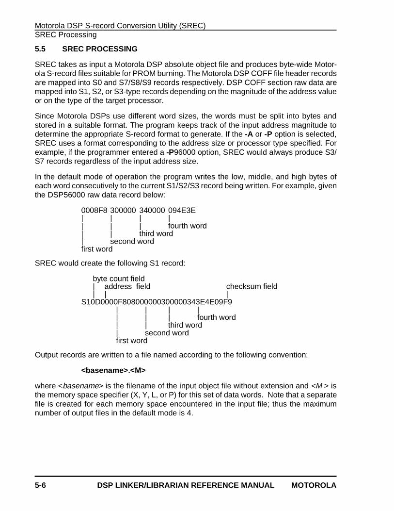
In the default mode of operation the program writes the low, middle, and high bytes ofeach word consecutively to the current S1/S2/S3 record being written. For example, giventhe DSP56000 raw data record below:
0008F8 300000 340000 094E3E| | | || | | fourth word| | third word| second wordfirst word
SREC would create the following S1 record:
byte count field| address field checksum field| | |
S10D0000F808000000300000343E4E09F9| | | || | | fourth word| | third word| second wordfirst word
Output records are written to a file named according to the following convention:
<basename>.<M>
where <basename> is the filename of the input object file without extension and <M > isthe memory space specifier (X, Y, L, or P) for this set of data words. Note that a separatefile is created for each memory space encountered in the input file; thus the maximumnumber of output files in the default mode is 4.
Motorola DSP S-record Conversion Utility (SREC)SREC Processing
MOTOROLA DSP LINKER/LIBRARIAN REFERENCE MANUAL 5-7
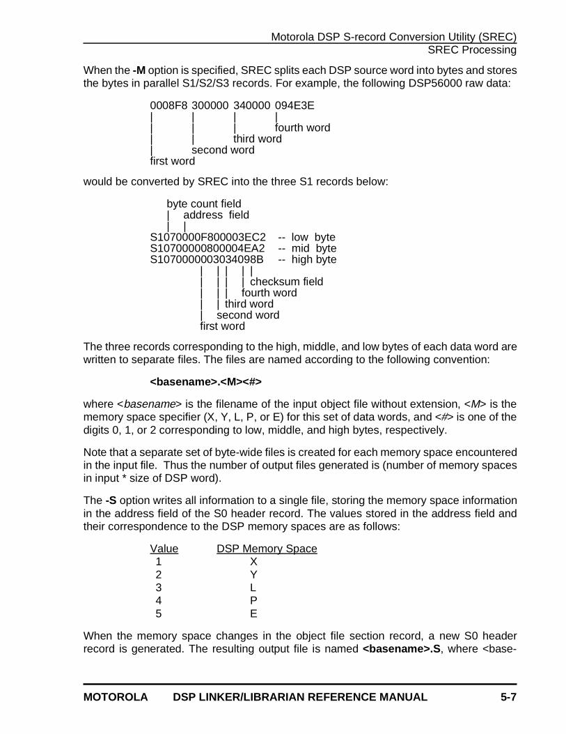
When the -M option is specified, SREC splits each DSP source word into bytes and storesthe bytes in parallel S1/S2/S3 records. For example, the following DSP56000 raw data:
0008F8 300000 340000 094E3E| | | || | | fourth word| | third word| second wordfirst word
would be converted by SREC into the three S1 records below:
byte count field| address field| |
S1070000F800003EC2 -- low byteS10700000800004EA2 -- mid byteS1070000003034098B -- high byte
| | | | || | | | checksum field| | | fourth word| | third word| second wordfirst word
The three records corresponding to the high, middle, and low bytes of each data word arewritten to separate files. The files are named according to the following convention:
<basename>.<M><#>
where <basename> is the filename of the input object file without extension, <M> is thememory space specifier (X, Y, L, P, or E) for this set of data words, and <#> is one of thedigits 0, 1, or 2 corresponding to low, middle, and high bytes, respectively.
Note that a separate set of byte-wide files is created for each memory space encounteredin the input file. Thus the number of output files generated is (number of memory spacesin input * size of DSP word).
The -S option writes all information to a single file, storing the memory space informationin the address field of the S0 header record. The values stored in the address field andtheir correspondence to the DSP memory spaces are as follows:
Value DSP Memory Space1 X2 Y3 L4 P5 E
When the memory space changes in the object file section record, a new S0 headerrecord is generated. The resulting output file is named <basename>.S , where <base-
Motorola DSP S-record Conversion Utility (SREC)S-Record File Format
5-8 DSP LINKER/LIBRARIAN REFERENCE MANUAL MOTOROLA
name> is the filename of the input object file without extension. The -M and -S options aremutually exclusive.
Address fields in DSP section records are copied as is to the appropriate S1, S2, or S3record. Subsequent S1, S2, or S3 record addresses are byte incremented until a new sec-tion is encountered or end-of-file is reached. In some cases the starting S1/S2/S3 recordaddress must be adjusted for byte addressing by multiplying the section start address bythe number of bytes in a DSP word. When the -B option is given, any section addressfields are adjusted to begin on a byte-multiple address. If the -W option is specified (thedefault) byte-incrementing is not done when generating S-record addresses, e.g. the S-record addresses are word-oriented rather than byte-oriented. The -B and -W optionshave no effect when used in conjunction with the -M mode, since in that case byte andword address mappings are 1:1.
Section records for L space memory contain words which are loaded into adjacent X andY memory locations. In these cases performing the default strict word addressing may beinappropriate. The -L option may be given to indicate that double-word addressing shouldbe used to generate subsequent S1/S2/S3 addresses after the initial load address. In ad-dition the -L option should be used when doing byte addressing since the initial load ad-dresses must be adjusted to account for double-word addressing in the object file. Ingeneral, it is a good idea to use the -L option whenever the input object file contains sec-tions which refer to L memory space.
5.6 S-RECORD FILE FORMAT
An S-record file consists of a sequence of specially formatted ASCII character strings.These character strings are made up of several fields which identify the record type,record length, memory address, code or data, and checksum. Each byte of binary datais encoded as a 2-character hexadecimal number, the first character representing thehigh-order 4 bits, and the second the low-order 4 bits of the byte.
5.6.1 S-Record Content
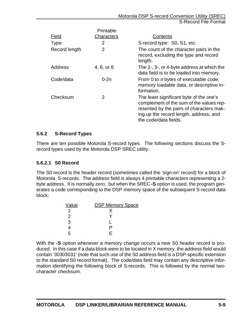
An S-record consists of 5 distinct fields: the TYPE field, the RECORD LENGTH, AD-DRESS field, CODE/DATA , and the CHECKSUM field.
Motorola DSP S-record Conversion Utility (SREC)S-Record File Format
MOTOROLA DSP LINKER/LIBRARIAN REFERENCE MANUAL 5-9
PrintableField Characters ContentsType 2 S-record type: S0, S1, etc.Record length 2 The count of the character pairs in the
record, excluding the type and record length.
Address 4, 6, or 8 The 2-, 3-, or 4-byte address at which the data field is to be loaded into memory.
Code/data 0-2n From 0 to n bytes of executable code, memory loadable data, or descriptive in-formation.
Checksum 2 The least significant byte of the one’s complement of the sum of the values rep-resented by the pairs of characters mak-ing up the record length, address, and the code/data fields.
5.6.2 S-Record Types
There are ten possible Motorola S-record types. The following sections discuss the S-record types used by the Motorola DSP SREC utility.
5.6.2.1 S0 Record
The S0 record is the header record (sometimes called the ‘sign-on’ record) for a block ofMotorola S-records. The address field is always 4 printable characters representing a 2-byte address. It is normally zero, but when the SREC -S option is used, the program gen-erates a code corresponding to the DSP memory space of the subsequent S-record datablock:
Value DSP Memory Space1 X2 Y3 L4 P5 E
With the -S option whenever a memory change occurs a new S0 header record is pro-duced. In this case if a data block were to be located in X memory, the address field wouldcontain ‘30303031’ (note that such use of the S0 address field is a DSP-specific extensionto the standard S0 record format). The code/data field may contain any descriptive infor-mation identifying the following block of S-records. This is followed by the normal two-character checksum.
Motorola DSP S-record Conversion Utility (SREC)S-Record File Format
5-10 DSP LINKER/LIBRARIAN REFERENCE MANUAL MOTOROLA
5.6.2.2 S1, S2, S3 Records
Each data record begins with the start characters S1, S2, or S3 followed by a byte count.These record types vary only by the length of their respective address fields. An S1 recordhas a 2-byte address field represented by 4 hexadecimal characters. An S2 record has a3-byte address field represented by 6 hexadecimal characters. An S3 record has a 4-byteaddress field represented by 8 hexadecimal characters. Data bytes follow the addressfield and are represented by hexadecimal character pairs. A two-character checksum ter-minates the data record. The SREC program guarantees that the number of bytes in anS1, S2, or S3 data record is an integral multiple of the word size of the target DSP.
5.6.2.3 S7, S8, S9 Records
These are end-of-file records and may appear only once in the S-record file. Each trailerrecord begins with the start characters S7, S8, or S9 followed by a byte count. As with thedata records these record types vary only by the length of their respective address fields.An S7 record has a 4-byte address field represented by 8 hexadecimal characters. An S8record has a 3-byte address field represented by 6 hexadecimal characters. An S9 recordhas a 2-byte address field represented by 4 hexadecimal characters. The address field inthe trailer record is used by the SREC program to store the end address given in the objectfile optional header record. A two-character checksum immediately follows the addressfield.
MOTOROLA DSP LINKER/LIBRARIAN REFERENCE MANUAL 6-1
Chapter 6 MOTOROLA DSP COFF FILE DUMP UTILITY (COFDMP)
6.1 INTRODUCTION
The Motorola DSP COFF file dump program COFDMP is a stand-alone utility that readsan absolute or relocatable Common Object File Format (COFF) file and produces a for-matted display of the object file contents. The entire file or only selected portions may beprocessed depending on command line options. The program also can generate eithercodes or symbolic references to entities such as symbol type and storage class.
6.2 INSTALLING COFDMP
The COFDMP program is distributed on various media and in different formats dependingon the host operating system environment. See Appendix G in the Motorola DSP As-sembler Reference Manual , HOST-DEPENDENT INFORMATION, for details on install-ing and operating COFDMP on your particular machine.
6.3 RUNNING COFDMP
The general format of the command line to invoke COFDMP is:
COFDMP [options] <files>
where:
[options]
Any of the following command line options. The options must precede thefile name. Option letters may be specified in either upper or lower case. Ifno option is supplied the entire input file is dumped.
Motorola DSP COFF File Dump Utility (COFDMP)COFDMP Options
6-2 DSP LINKER/LIBRARIAN REFERENCE MANUAL MOTOROLA
6.4 COFDMP OPTIONS
-C
Dump the string table of the specified file. This information may not bepresent if the object file has been stripped.
Example: COFDMP -C fft16.cld
In this example, the symbol table is listed from the absolute object fileFFT16.CLD.
-D<dmpfil>
This option specifies that a dump file is to be created for cofdmp output.<dmpfil> can be any legal operating system filename, including an optionalpathname.
If the -D option is not specified, then the program will route dump output tothe standard output (usually the console or terminal screen) by default. The-D option should be specified only once. If the file named in the -D optionalready exists, it will be overwritten.
Example: COFDMP -D filter.dmp filter.cld
In this example, the absolute load file FILTER.CLD will be dumped tothe output file FILTER.DMP.
-F
Dump the file header of the specified file.
Example: COFDMP -F fft16.cln
In this example, the file header is listed from the relocatable objectfile FFT16.CLN.
-H
Dump the section headers of the specified file.
Example: COFDMP -H fft16.cld
In this example, the section headers are listed from the absolute ob-ject file FFT16.CLD.
Motorola DSP COFF File Dump Utility (COFDMP)COFDMP Options
MOTOROLA DSP LINKER/LIBRARIAN REFERENCE MANUAL 6-3
-L
Dump the source file line number information from the specified file. Thisinformation may not be present if the object file has been stripped.
Example: COFDMP -L fft16.cln
In this example, the source file line number information is listed fromthe relocatable object file FFT16.CLN.
-O
Dump the optional header of the specified file.
Example: COFDMP -O fft16.cln
In this example, the optional header is listed from the relocatable ob-ject file FFT16.CLN.
-Q
On some hosts COFDMP displays a banner on the console when invoked.This option inhibits the banner display. It has no effect on hosts where thesignon banner is not displayed by default.
Example: COFDMP -Q myprog.cld
Dump the file MYPROG.CLD but do not display the signon banner onthe console.
-R
Dump section relocation entries from the specified file. Only relocatable ob-ject files will contain this information.
Example: COFDMP -R fft16.cln
In this example, the section relocation information is listed from therelocatable object file FFT16.CLN.
-S
Dump the section raw data from the specified file.
Example: COFDMP -S fft16.cld
In this example, the section raw data is listed from the absolute objectfile FFT16.CLD.
Motorola DSP COFF File Dump Utility (COFDMP)COFDMP Processing
6-4 DSP LINKER/LIBRARIAN REFERENCE MANUAL MOTOROLA
-T
Dump the symbol table from the specified file. This information may not bepresent if the object file has been stripped.
Example: COFDMP -T fft16.cln
In this example, the symbol table is listed from the relocatable objectfile FFT16.CLN.
-V
Dump the specified file symbolically, using names for bit flags, symboltypes, and storage classes.
Example: COFDMP -V fft16.cld
In this example, the entire contents of the absolute object fileFFT16.CLD is dumped symbolically.
<files>
A list of operating system compatible filenames. If no pathname is specifiedfor a file, the program will look for that file in the current directory. An explicitfilename must be provided; there is no default extension for the input file.
6.5 COFDMP PROCESSING
The COFDMP program reads the input file and writes a formatted dump of the file con-tents to the standard output (unless the -D command line option is given). I/O redirectionmay be used to send the output to a file if the host operating system supports it.
The program currently will not dump individual modules from library files; they must be ex-tracted and then dumped. Also note that if the file has been stripped some informationmay no longer be available in the file, such as relocation information, line number entries,and symbol and string table data.
The input file must be a Motorola DSP COFF object file, either absolute or relocatable.See Appendix E in the Motorola DSP Assembler Reference Manual , MOTOROLA DSPOBJECT FILE FORMAT, for more information on Motorola DSP COFF object files.
MOTOROLA DSP LINKER/LIBRARIAN REFERENCE MANUAL A-1
Appendix A LINKER MESSAGES
A.1 INTRODUCTION
Linker messages are grouped into four categories:
Command Line Errors
These errors indicate invalid command line options, missing filenames, file openerrors, or other invocation errors. Command line errors generally cause the Linkerto stop processing.
Warnings
Warnings notify the programmer of suspect constructs but do not otherwise affectthe object file output.
Errors
These errors indicate problems with object file format, size of address fields, andsyntax. In these cases the resulting object code is generally not valid.
Fatal
Fatal errors signify serious problems encountered during the link process such aslack of memory, file not found, or other internal errors. The Linker halts immediate-ly.
The Linker also will provide information on the file name, module ID, and section locationof the error, if it can be ascertained. Messages are always routed to standard output.
Linker MessagesCommand Line Errors
A-2 DSP LINKER/LIBRARIAN REFERENCE MANUAL MOTOROLA
A.2 COMMAND LINE ERRORS
Align not valid with incremental link - ignored
Both the -I and -A options were given on the command line. The -A option auto-aligns circular buffers in the output file, but an incrementally linked file (-I) must re-tain original buffer placement for future linking. If both are specified, the Linkerdoes not auto-align.
Cannot open command fileCannot open library fileCannot open map fileCannot open memory control fileCannot open object file
The file associated with a -F, -L, -M, -R, or -B command line option was not foundor could not be opened.
Default object file not allowed in incremental link
When performing an incremental link using the -I option the -B option must be usedin order to name the output object file. The default naming convention cannot beused because it might overwrite one of the input files.
Duplicate map file specified - ignoredDuplicate memory control file specified - ignoredDuplicate object file specified - ignored
More than one -M, -R, or -B option was encountered on the command line.
Illegal command line option
The option specified on the command line was not recognized by the Linker.
Illegal command line -E option
Neither of the qualifiers -A or -W were provided with the -E option.
Illegal command line -X option argument
The argument given with the -X command line option was not recognized by theLinker.
Invalid syntax for command line -E option
There must be whitespace between the -E option and its filename argument.
Missing argument for command line -E option
The -E command line option must have a filename argument.
Linker MessagesCommand Line Errors
MOTOROLA DSP LINKER/LIBRARIAN REFERENCE MANUAL A-3
Missing command line option argument
The expected arguments following a command line specifier were missing.
Missing object filename
There must be at least one object filename specified on the command line.
No modules linked - empty object file
An object file header record was never found in the input.
Object file name same as executable file nameObject file name same as map file name
One of the object files appeared to the Linker to have the same name as the spec-ified executable or map file. The Linker aborts rather than potentially writing overan input object file.
Options for both debug and strip specified - strip ignored
Both the -G and -Z options were given on the command line. The -G option takesprecedence.
Seek failure
An attempt to seek randomly to verify a library file has failed.
Strip not valid with incremental link - ignored
Both the -I and -Z options were given on the command line. The -I option takes pre-cedence.
Linker MessagesWarnings
A-4 DSP LINKER/LIBRARIAN REFERENCE MANUAL MOTOROLA
A.3 WARNINGS
Actual length of section greater than specified size
The length of a section is greater than the absolute size given in a memory controlfile SECSIZE directive.
Duplicate global symbol
A global symbol in one object file was also defined by the same name in a differentmodule.
Duplicate XDEF symbol
An external symbol in one object file was also defined by the same name in a dif-ferent module.
EMI 8-bit memory value truncatedEMI 12-bit memory value truncatedEMI 16-bit memory value truncatedEMI 20-bit memory value truncated
The value in a data directive was too large for the current EMI memory configura-tion.
Empty bit mask field
The first operand of a BFxxx -type instruction was zero.
Expression value outside fractional domain
The expected fractional value was not within the range -1.0 <= m < 1.
Incompatible debug format
The input object file debug information is not compatible with the current version ofthe Linker.
Memory model mismatch
An object file produced by the C compiler is incompatible with other files in the inputstream. This can result when C source files compiled using X memory for data stor-age and others compiled using Y memory for data storage are linked. The Linkercannot reconcile the memory differences.
No modules linked - empty object file
An object file header record was never found in the input.
Linker MessagesWarnings
MOTOROLA DSP LINKER/LIBRARIAN REFERENCE MANUAL A-5
Object file major version number greater than Linker major version numberObject file minor version number greater than Linker minor version number
The input file version number generated by the assembler does not match the cur-rent version number of the Linker.
Options for both debug and strip specified - strip ignored
Both the -G and -Z options were given on the command line. The -G option takesprecedence.
Overlay buffer not aligned
A circular buffer inside a relocatable overlay will be misaligned when the overlay istransferred at runtime. The Linker makes no attempt to realign buffers located in-side relative overlay blocks.
Remapping regionRemapping section
A REGION or SECTION directive set an existing memory space to a different map-ping attribute.
Section already set as absolute
A section listed as ordered in a memory control file SECTION record was found tobe already located absolutely.
String truncated in expression evaluation
Only the first four characters of a string constant are used during expression eval-uation.
Strip not valid with incremental link - ignored
The -I and -Z command line options are mutually exclusive. The -I option takes pre-cedence.
Linker MessagesErrors
A-6 DSP LINKER/LIBRARIAN REFERENCE MANUAL MOTOROLA
A.4 ERRORS
Arithmetic exception
An internal floating point exception occurred while evaluating an expression. Theresult of the evaluation is probably not valid.
Autoaligned buffer not allowed in overlay
A circular buffer inside a relocatable overlay cannot be auto-aligned because theoverlay block will be moved, voiding any benefit of optimal buffer placement.
Binary constant expected
A character other than ASCII '0' or '1' either followed the binary constant delimiter(%) or appeared in an expression where a binary value was expected by default.
Bit mask cannot span more than eight bits
If the first operand of a BFxxx -type instruction was shifted one bit to the right untilthe low-order bit was a 1, the resulting value must not exceed $FF hexadecimal.
Buffer block too large
The runtime location counter overflowed while the Linker was attempting to allo-cate storage for a data buffer. The Linker automatically advances the programcounter to the next valid base address given the size of the modulo or reverse carrybuffer.
Buffer out of order
The buffer sequence numbers in the input stream are out of phase.
Cannot nest regions
A REGION directive in the memory control file may not appear between anotherREGION/ENDR pair.
Cannot open include file
The file specified in a memory control file INCLUDE directive was not found orcould not be opened.
Decimal constant expected
A character other than ASCII '0' through '9' either followed the decimal constant de-limiter (`) or appeared in an expression where a decimal value was expected bydefault.
Divide by zero
The expression evaluator detected a divide by zero.
Linker MessagesErrors
MOTOROLA DSP LINKER/LIBRARIAN REFERENCE MANUAL A-7
Duplicate global symbol
Two identically named global symbols have been found.
Duplicate local symbol
Two identically named symbols have been found which are local to the same sec-tion.
Duplicate region assignment for section
A memory control file SECTION directive with the same name and memory at-tributes was assigned to more than one region.
Duplicate special symbol
The Linker reserves a few symbol names to deal with certain floating point entitiessuch as Infinity and Not-a-Number. These symbols are Inf, Nan, Tiny, and Huge.
ENDR without corresponding REGION directive
An ENDR directive in the memory control file did not have a matching REGION di-rective.
Expression cannot have a negative value
The MAP PAGE directive does not allow negative expression arguments.
Expression contains forward references
The expression representing a location counter number contains a term which theexpression evaluation logic cannot resolved (e.g. an undefined symbol).
Expression involves incompatible memory spaces
The memory space attribute is regarded by the Linker as a type, in the same sensethat high level languages use type for variables. Symbols may have memory spaceattributes of X, Y, L, P(rogram), E(MI), or N(one); only N is fully compatible with allother attributes. In this case, two operands were evaluated with different memoryspace attributes, neither of which was N.
Expression result must be absolute
Certain directives and some Linker usage require absolute values as arguments oroperands.
Expression result must be integer
The expression refers to an address; therefore the result must be an integer withinthe address range of the target DSP.
Linker MessagesErrors
A-8 DSP LINKER/LIBRARIAN REFERENCE MANUAL MOTOROLA
External reference not allowed in expression
The expression contained an undefined symbol which the expression evaluationlogic cannot resolve.
Extra characters beyond expression
The expression evaluator found extra characters after the end of a valid expres-sion. Unbalanced parentheses can cause this error.
Extra characters in function argument or missing ')' for function
Mismatched parentheses or wrong number of parameters in a function invocation.
Floating point constant expected
A character other than ASCII '0' through '9', 'e' or 'E', or '.' appeared in an expres-sion where a floating point value was expected by default.
Floating point not allowed in relative expression
Relative expressions are generally used for address computation, therefore a float-ing point value would not be appropriate.
Hex constant expected
A character other than ASCII '0' through '9', 'a' through 'f', or 'A' through 'F' eitherfollowed the hexadecimal constant delimiter ($) or appeared in an expressionwhere a hexadecimal value was expected by default.
Illegal memory counter specified
The memory counter specifier must be H for the high counter, L for the low counter,or absent for the default counter.
Illegal memory map character
The memory map indicator must be I for internal memory, E for external memory,R for ROM, A for port A, B for port B, or absent for no explicit mapping.
Illegal operator for floating point element
Bitwise operators are invalid for floating point values.
Illegal option
A bad argument was provided with the -X command line option.
Invalid address expression
The memory space attributes of the expression operands are incompatible.
Linker MessagesErrors
MOTOROLA DSP LINKER/LIBRARIAN REFERENCE MANUAL A-9
Invalid address relocation field
Either a new record began or end-of-file was reached when the Linker was readingthe address specification in a memory file BASE or SECTION record.
Invalid EMI memory designation
The EMI memory type does not fall within an appropriate range of values.
Invalid function name
The Linker could not match an internal function name.
Invalid include file name
The filename associated with a memory control file INCLUDE directive is missingor malformed.
Invalid MAP optionInvalid MAP option fieldInvalid MAP page fieldInvalid MAP record field
One of the options or fields in a memory control file MAP record was not recog-nized by the Linker.
Invalid memory space field
The memory space specifier for a SIZSYM directive was not found.
Invalid module name field
The module name field associated with a memory control file IDENT directive ismissing or malformed.
Invalid overlay base address
An overlay base address was given that specified an address within another over-lay segment.
Invalid page length specified
The minimum page length allowed by the MAP PAGE directive is 10 lines perpage. The maximum is 255.
Invalid page width specified
The minimum page width allowed by the MAP PAGE directive is 1 column per line.The maximum is 255.
Linker MessagesErrors
A-10 DSP LINKER/LIBRARIAN REFERENCE MANUAL MOTOROLA
Invalid region name field
The region name associated with a memory control file REGION directive is miss-ing or malformed.
Invalid relative expression
The terms of a relative expression may only participate in addition and subtractionoperations and must have opposing signs.
Invalid relocation type field
An invalid record type was encountered in the memory control file.
Invalid reserve range syntax
The syntax for the memory control file RESERVE is such that the range is given astwo values from the same memory space and mapping, separated by two periodsin succession (..).
Invalid revision number field
The revision number field in a memory control file IDENT record is not valid. Thevalue must be a decimal integer number.
Invalid section name field
The section name associated with a memory control file SECTION directive ismissing or malformed.
Invalid shift amount
A shift expression must evaluate to within the range 0 <= n <= 32.
Invalid source line number
The source line number in a relocation expression must be an integer.
Invalid start address expression
The end address expression in the optional header record is malformed.
Invalid start address field
The start address field in a memory control file START record is not valid. The con-tents must be a positive numeric value.
Invalid symbol
Symbols are limited to 512 characters. The first character must be alphabetic or theunderscore character (A-Z, a-z, _ ). The remaining characters must be alphanu-meric, including the underscore character (A-Z, a-z, 0-9, _ ).
Linker MessagesErrors
MOTOROLA DSP LINKER/LIBRARIAN REFERENCE MANUAL A-11
Invalid symbol memory mapping
The memory type for a symbol in the symbol table does match a valid Linker mem-ory configuration.
Invalid symbol name field
Either a new record began or end-of-file was reached when the Linker was readingthe name specification in a memory file SYMBOL record.
Invalid symbol value field
Either a new record began or end-of-file was reached when the Linker was readingthe value specification in a memory file SYMBOL record.
Invalid version number field
The version number field in a memory control file IDENT record is not valid. Thevalue must be a decimal integer number.
Left margin exceeds page width
The blank left margin value in the MAP PAGE directive exceeds the default orspecified page width parameter.
Missing '(' for function
Parentheses are not balanced in an internal function call.
Missing ')' in expression
Parentheses are not balanced in an expression.
Missing ']' in expression
Square brackets are not balanced in an expression.
Missing '}' in expression
Curly braces are not balanced in an expression.
Missing expression
An expression was expected by the expression evaluator.
Missing filename
The filename associated with a memory control file INCLUDE directive is missing.
Missing option
The argument associated with the -X command line option is missing.
Linker MessagesErrors
A-12 DSP LINKER/LIBRARIAN REFERENCE MANUAL MOTOROLA
Missing quote in string
A single or double quote character was expected by the string parsing routines.
Missing string after concatenation operator
The string concatenation operator (++) must be followed by another quoted string.
No previous function declaration
An end-of-function symbol record was encountered without a corresponding func-tion type symbol record.
Operation not allowed with address term
Only addition and subtraction are allowed in expressions with address terms.
Overlay address involves incompatible memory spaces
The memory space attribute is regarded by the Linker as a type, in the same sensethat high level languages use type for variables. Symbols may have memory spaceattributes of X, Y, L, P(rogram), E(MI), or N(one); only N is fully compatible with allother attributes. In this case, the runtime overlay address was found to be incom-patible with the memory space used as the overlay origin.
Overlay out of order
The overlay sequence numbers in the input stream are out of phase.
Page length too small for specified top and bottom margins
The sum of the top and bottom margins specified in the MAP PAGE directive isgreater than the page length - 10.
Page length too small to allow default bottom margin
The bottom margin exceeds the page length specified in the MAP PAGE directive.
Region high address lower than base address
A memory control file BASE directive had a greater value than a correspondingMEMORY directive for a given region.
Region size/address mismatch
The size field in a memory control file REGION directive does not correlate with thecomputed size derived from BASE and MEMORY directives for the same region.
Region without associated ENDR directive
A REGION directive in the memory control file did not have a matching ENDR di-rective.
Linker MessagesErrors
MOTOROLA DSP LINKER/LIBRARIAN REFERENCE MANUAL A-13
Relative expression must be integer
A relative expression must evaluate to an integer value.
Relative terms from different sections not allowed
Two relative terms from different sections may not participate in an arithmetic op-eration since the result might not be meaningful. This error may be disabled withthe Linker XC option.
Section not found
The section named in a SECTION, SBALIGN , or SECSIZE directive could not befound by the Linker.
Section padding percentage too small
The percentage of padding in a memory control file SECSIZE record must begreater than 100.0.
Specified address greater than maximum memory address
The directive address is greater than the argument given in a previously encoun-tered MEMORY directive for this region.
Specified size greater than maximum memory address
The size given in a memory control file SECSIZE directive is greater than the argu-ment given in a previously encountered MEMORY directive for this region.
Symbol already defined
A symbol assumed to be unresolved and named in a memory file SYMBOL recordhas already been defined.
Symbol name too long
Symbols are limited to 512 characters. The first character must be alphabetic or theunderscore character (A-Z, a-z, _). The remaining characters must be alphanumer-ic, including the underscore character (A-Z, a-z, 0-9, _).
Symbol tag mismatch
A matching tag reference could not be found for a tagged symbol table entry.
Syntax error - expected ':'Syntax error - expected '):'
The Linker was expecting the end of either a memory space designator or a loca-tion counter expression while parsing a memory attribute string.
Linker MessagesErrors
A-14 DSP LINKER/LIBRARIAN REFERENCE MANUAL MOTOROLA
Syntax error - expected comma
The Linker was expecting a comma while parsing the arguments of a function.
Syntax error - expected quote
The Linker was expecting the start of a quoted string.
Syntax error in expression
The syntax in a memory file BASE or SECTION record is not correct (possiblymissing a colon before the address specification).
Unresolved overlay base address
The symbol used as the runtime overlay address was never resolved during the fix-up phase.
Linker MessagesFatal Errors
MOTOROLA DSP LINKER/LIBRARIAN REFERENCE MANUAL A-15
A.5 FATAL ERRORS
Arithmetic exception
An internal floating point exception occurred while evaluating an expression.
Cannot determine file size
The size of the input link module could not be determined.
Cannot find GLOBAL section
The memory control file processing logic could not locate a GLOBAL sectionrecord.
Cannot find section record
The Linker was unable to locate a previously accessed section record. This is a se-rious internal error that should be reported to Motorola.
Cannot open library fileCannot open object file
The Linker attempted to open a library or object file for reprocessing on the secondpass and the open failed.
Cannot read file header from library moduleCannot read file header from object module
An I/O error occurred which prevented the Linker from reading the file headers ina library or object file.
Cannot read line number entries from object moduleCannot read module string table sizeCannot read object module section headersCannot read object module string tableCannot read object module symbol entriesCannot read raw data from object moduleCannot read relocation entries from object module
An I/O error occurred which prevented the Linker from reading entities in the inputobject file.
Cannot read optional header from library moduleCannot read optional header from object module
An I/O error occurred which prevented the Linker from reading the optional head-ers in a library or object file.
Linker MessagesFatal Errors
A-16 DSP LINKER/LIBRARIAN REFERENCE MANUAL MOTOROLA
Cannot seek to library module symbol table
An I/O error occurred which prevented the Linker from positioning correctly whenattempting to read a library module symbol table.
Cannot seek to object module line number entriesCannot seek to object module raw dataCannot seek to object module relocation entriesCannot seek to object module section headersCannot seek to object module symbol table
An I/O error occurred which prevented the Linker from positioning correctly in theinput object file.
Cannot seek to start of line number entriesCannot seek to start of object dataCannot seek to start of object fileCannot seek to start of object moduleCannot seek to start of section headersCannot seek to start of string tableCannot seek to start of symbol table
An I/O error occurred which prevented the Linker from positioning correctly in theoutput object file.
Cannot set current section
The current module section map has been corrupted. This is a serious internal er-ror that should be reported to Motorola.
Cannot set section counter
The current module counter map has been corrupted. This is a serious internal er-ror that should be reported to Motorola.
Cannot write left margin to map fileCannot write new line to map fileCannot write new page to map fileCannot write page header to map fileCannot write string to map file
An I/O error occurred which prevented the Linker from writing data to the outputmap file.
Cannot write .text/.data headers to object fileCannot write file header to object fileCannot write line number entries to object fileCannot write optional header to object fileCannot write padding to object file
Linker MessagesFatal Errors
MOTOROLA DSP LINKER/LIBRARIAN REFERENCE MANUAL A-17
Cannot write raw data to object moduleCannot write relocation entries to object moduleCannot write section headers to object moduleCannot write string table to object fileCannot write symbols to object file
An I/O error occurred which prevented the Linker from writing data to the outputobject file.
Compare select failure
The comparison indicator passed to the evaluator selection logic was not valid.This is a serious internal error that should be reported to Motorola.
Current relocation map not available
A valid relocation map could not be accessed. This is a serious internal error thatshould be reported to Motorola.
Current relocation section not available
A valid relocation section could not be accessed. This is a serious internal error thatshould be reported to Motorola.
Current section not available
A valid current section could not be accessed. This is a serious internal error thatshould be reported to Motorola.
Duplicate section entry
An attempt was made to place two sections with the same name and memory at-tributes into a single region.
Expression operator failure
Expression operator lookup has failed. This is a serious internal error that shouldbe reported to Motorola.
Expression stack underflow
The internal expression evaluation list is out of sequence. This is a serious internalerror that should be reported to Motorola.
Fatal segmentation or protection fault; contact Motorola
A program error has caused the Linker to access an invalid host system address.This generally indicates a bug in the Linker software.
Linker MessagesFatal Errors
A-18 DSP LINKER/LIBRARIAN REFERENCE MANUAL MOTOROLA
File contains no relocation information
An absolute object file was specified as input to the Linker.
Invalid data block type
Internal section type information has been corrupted.
Invalid global section
A section with a sequence number of zero did not have the proper global sectionname.
Invalid library module header
An I/O error occurred when attempting to read a library module header.
Invalid library module header format
The module header for a file contained in a library has been corrupted.
Invalid object file for target processor
Incompatible target processor object files were specified as input to the Linker.
Invalid operand bit size
The bit size operand in an object file expression was not recognized.
Invalid section number
A new section encountered by the Linker does not have a unique section number.
Invalid section number data
The section number in a section symbol record is out of range.
Map option select failure
The value returned from the mapping selection logic was not valid. This is a seriousinternal error that should be reported to Motorola.
No current counter map
A valid counter map was not available. This is a serious internal error that shouldbe reported to Motorola.
Offset failure
An attempt to save the object file offset has failed.
Linker MessagesFatal Errors
MOTOROLA DSP LINKER/LIBRARIAN REFERENCE MANUAL A-19
Option select error
The value returned from the option selection logic was not valid. This is a seriousinternal error that should be reported to Motorola.
Out of memory - link aborted
There is not enough internal memory to perform dynamic allocation. Since theLinker stores all working information in memory, including symbol and section in-formation, there is the possibility that memory will be exhausted if many symbolsor sections are defined in a single Linker run.
Relocation type select failure
A value returned from the memory control file function select logic is bad. This isa serious internal error that should be reported to Motorola.
Section map lookup failure
A valid section map could not be accessed. This is a serious internal error thatshould be reported to Motorola.
Section nesting error
The section nesting count is out of phase.
Seek failure
An attempt to seek randomly in the object file has failed.
Symbol map lookup failure
A valid symbol map could not be accessed. This is a serious internal error thatshould be reported to Motorola.

MOTOROLA DSP LINKER/LIBRARIAN REFERENCE MANUAL B-1
Appendix B LIBRARIAN MESSAGES
B.1 INTRODUCTION
Librarian messages are grouped into three categories:
Command Line Errors
These errors indicate invalid command line options, missing filenames, file openerrors, or other invocation errors. Command line errors generally cause the librar-ian to stop processing.
Warnings
Warnings indicate that a file cannot be open, or that a module already exists ordoes not exist in the library. The librarian continues processing.
Fatal Errors
Fatal errors signify serious problems encountered during library processing suchas lack of memory, file not found, or other internal errors. The librarian halts imme-diately.
Librarian MessagesCommand Line Errors
B-2 DSP LINKER/LIBRARIAN REFERENCE MANUAL MOTOROLA
B.2 COMMAND LINE ERRORS
argument missing
A necessary argument, such as a module name, was missing from the librariancommand line.
unknown option
The given command line option is not recognized. The librarian continues as if the-U option had been given.
Librarian MessagesWarnings
MOTOROLA DSP LINKER/LIBRARIAN REFERENCE MANUAL B-3
B.3 WARNINGS
<module> already in library
In an add operation a module with the same name as the one specified already ex-ists in the library.
<module> not in library
The named module was not found in the specified library. This error can occur forexample during a replace operation.
ambiguous command
The interactive command issued at the librarian prompt was not unique to the setof characters entered.
cannot open module file
The named module file could not be open. Either the file does not exist or there wasan I/O error.
command requires library name
All interactive commands require that the library name follow the command nameon the input line.
duplicate module name
The same module name was entered twice on the command line.
invalid command
The librarian did not recognize an interactive command.
Librarian MessagesFatal Errors
B-4 DSP LINKER/LIBRARIAN REFERENCE MANUAL MOTOROLA
B.4 FATAL ERRORS
add requires explicit module names
At least one module name must be given for an add operation.
cannot allocate argument vectorcannot allocate copy buffercannot allocate input buffercannot allocate module structurecannot allocate module vectorcannot allocate output buffer
The librarian did not have enough memory to allocate internal data structures.
cannot create temporary file name
The librarian was unable to create a temporary file name for the library scratch file.
cannot open command file
The named command line option file does not exist, or there was an I/O error.
cannot open library file
The named library file does not exist, or there was an I/O error.
cannot open temporary file
An I/O error prevented the librarian from opening the temporary library scratch file.
cannot read module header
The librarian could not read the module header in the specified library. Either an I/O error occurred, or the library file is empty.
cannot rename <file>
An error occurred while attempting to rename a library file.
cannot save command file arguments
The librarian could not obtain enough memory to store the module names given inthe command line option file.
cannot stat module
The librarian could not obtain date and time information for the named module.
Librarian MessagesFatal Errors
MOTOROLA DSP LINKER/LIBRARIAN REFERENCE MANUAL B-5
cannot write end of module marker
An I/O error occurred preventing the librarian from writing the end of module mark-er to the library file.
cannot write header to library file
An I/O error occurred preventing the librarian from writing the module header to thelibrary file.
delete requires explicit module names
At least one module name must be given for a delete operation.
error reading file
An I/O error occurred while reading a file.
error writing file
An I/O error occurred while writing a file.
fatal errors - <library> not altered
This is an informative message indicating that the named library was not changedbecause of previous fatal errors.
file I/O error
An I/O error occurred while either reading or writing a file.
improper module header format
A module header in the library file has been corrupted, or the specified file is not alibrary file.
library file already exists
In a create operation the named library file already exists.
missing command filename
The required argument on a -F command line option was missing.
out of memory - librarian aborted
There is not enough internal memory to perform dynamic allocation. Since the li-brarian stores all working information in memory, there is the possibility that mem-ory will be exhausted if many modules are processed in a single library operation.

MOTOROLA DSP LINKER/LIBRARIAN REFERENCE MANUAL C-1
Appendix CLINKER MAP FILE FORMAT
C.1 INTRODUCTION
The Linker optionally produces a memory map listing file when the command line -M isspecified. See Chapter 1, Running the Linker for more information on command line andmap listing options. If the -M command line option is given, the map listing goes to the filenamed as the option argument; if no argument is specified, the map listing file takes thename of the first object file on the command line and changes the extension to .MAP (seeChapter 1).
C.2 MAP FILE COMMENTARY
Figure C-1 is a Linker-generated map listing of a sample application. The listing illustratesa selection of the format and reporting features provided by the Linker. The following sec-tion highlights some of those features.
At the top of every map listing page is a banner which identifies the Linker and lists itsversion number, the date and time of linking, the current input file name, and the pagenumber. The map file page length, width, and margins can be controlled by the memorycontrol file MAP PAGE record (see Chapter 3, MAP PAGE Map File Format Control).
The first titled grouping in the report is a list of sections sorted by starting address. Thislist of sections is subdivided by DSP memory and ordered by counter such that all X de-fault (counter 0) memory references are grouped together, followed by X low (counter 1)memory, and so forth. Each line gives the starting address, ending address, and length ofevery uniquely-named section in the Linker input stream if that section contained code ordata for the current memory space. The length reflects the total of all section fragmentsassimilated from separate input files. As a result there is only one line for each sectioneven if the section appears in different files. If sections are located such that they overlapin memory the Linker will flag the overlap in the map file to the right of the section name.The link map also shows any unused memory areas between allocated blocks. Theselines may be disabled using the MAP OPT NOUNUSED directive (see Chapter 3, MAPOPT Map File Contents Control).
A section name may be repeated for a given memory space if that section contains buff-ers, overlays, or absolute blocks. In this case the start, end, and size of the block is re-ported and the type of block is placed to the right of the section name. On page 1 of the
Linker Map File FormatMap File Commentary
C-2 DSP LINKER/LIBRARIAN REFERENCE MANUAL MOTOROLA
example listing section SECT1 contains a modulo buffer of length 32 starting at address20 hexadecimal in X memory. On the same page the section SECT2 has an overlay seg-ment of length 7 that is loaded at address 12 hexadecimal in P memory. The listing of sec-tions by address can be turned off with the memory control file MAP OPT NOSECADDRdirective (see Chapter 3, MAP OPT Map File Contents Control).
The next titled grouping on the map report (page 2) is a list of sections sorted by name.The name of the section is given along with the start, end, and length of blocks in eachDSP memory space. As in the section by address listing special blocks such as buffers oroverlays are shown on a line by themselves. The section by name report can be disabledby using the memory control file MAP OPT NOSECNAME directive (see Chapter 3, MAPOPT Map File Contents Control).
After the section-oriented reports there appears on page 3 of the map file a symbol listingordered by name. Each line starts with the symbol name (truncated to 16 characters), fol-lowed by the symbol type (integer or floating point), the memory space if any and value,the name of the section in which the symbol is defined, and the symbol attributes. A sym-bol can be absolute or relative (REL), local, XDEFed (EXTERN), or global, and possiblyassociated with a buffer or overlay. This portion of the map listing may be omitted throughthe memory control file MAP OPT NOSYMNAME directive (see Chapter 3, MAP OPTMap File Contents Control).
The last page of the listing shows a symbol listing sorted by value. The listing by value canbe turned off with the memory control file MAP OPT NOSYMVAL directive (see Chapter3, MAP OPT Map File Contents Control).
The final report group lists the unresolved externals found during the link phase. This con-sists of all the symbol references for which there was no corresponding definition found inthe link input. The Linker indicates the symbol name and the module in which the refer-ence was made.
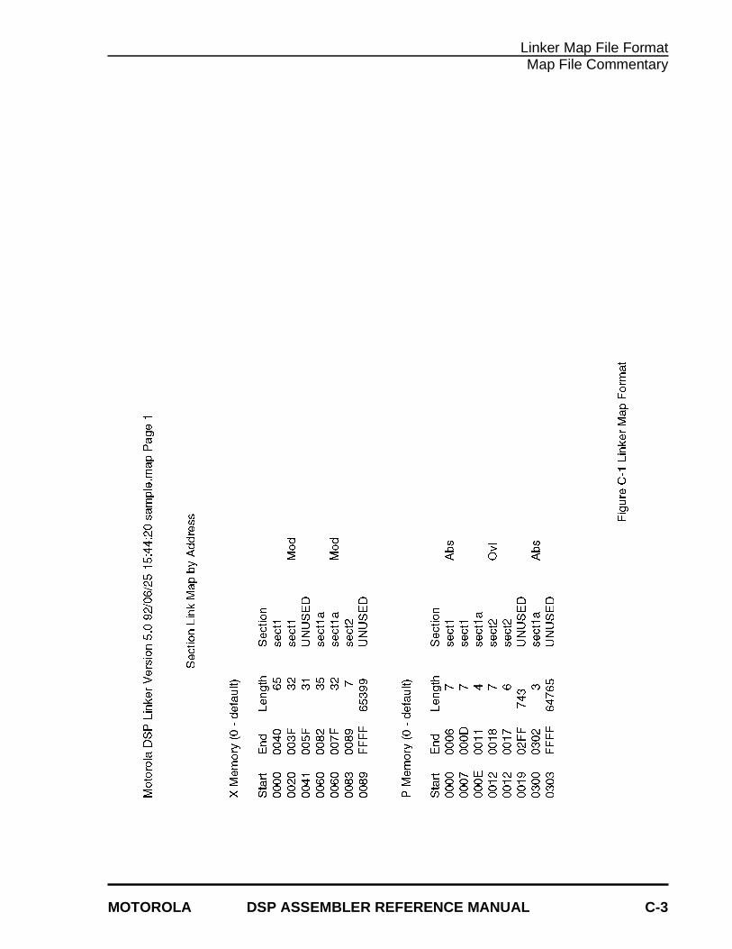
Linker Map File FormatMap File Commentary
MOTOROLA DSP ASSEMBLER REFERENCE MANUAL C-3
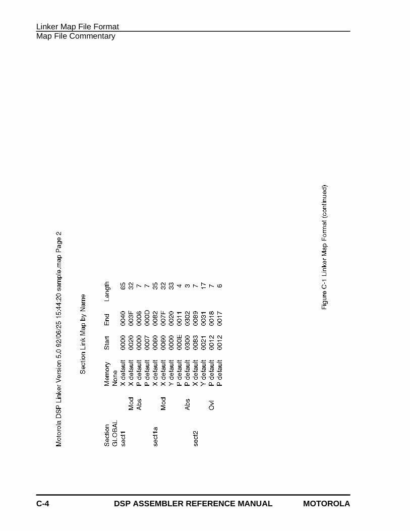
Linker Map File FormatMap File Commentary
C-4 DSP ASSEMBLER REFERENCE MANUAL MOTOROLA
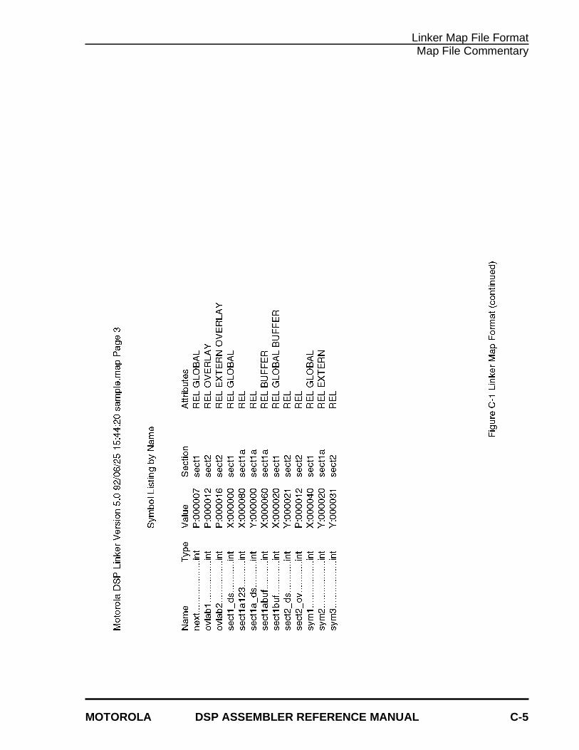
Linker Map File FormatMap File Commentary
MOTOROLA DSP ASSEMBLER REFERENCE MANUAL C-5
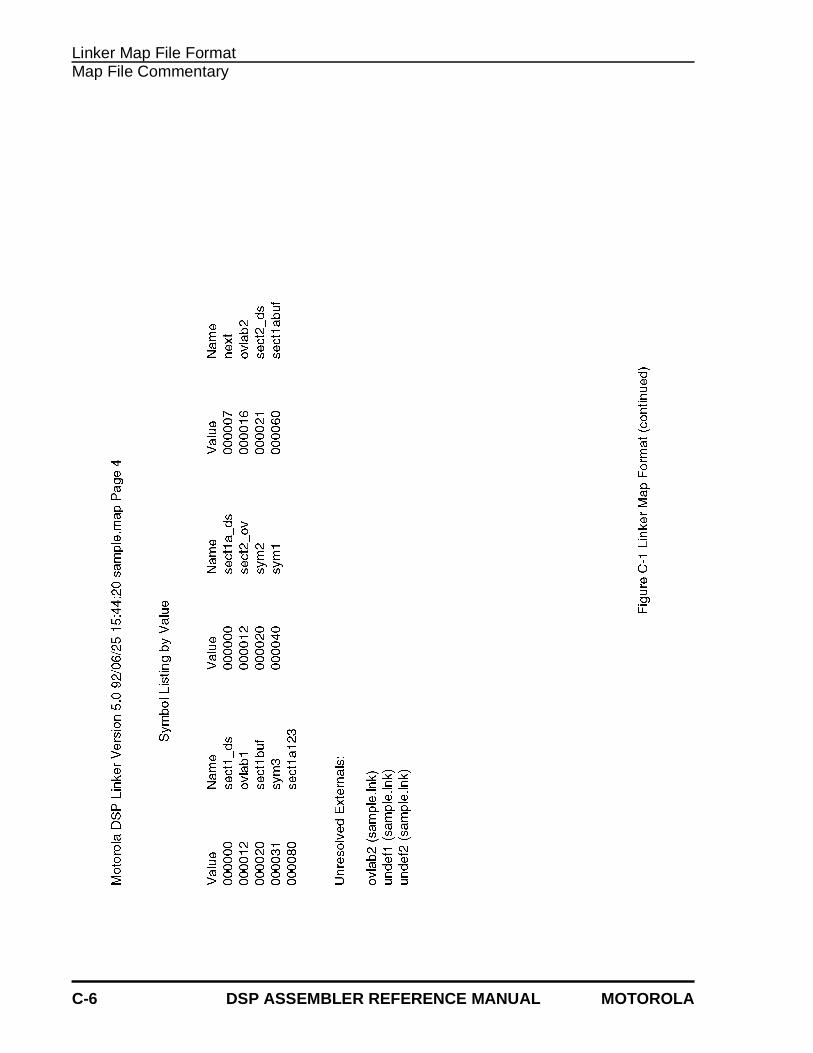
Linker Map File FormatMap File Commentary
C-6 DSP ASSEMBLER REFERENCE MANUAL MOTOROLA
INDEX
MOTOROLA DSP LINKER/LIBRARIAN REFERENCE MANUAL I-1
— B —
Bufferauto-align .................................... 1-3circular ......................................... 2-3
— C —
Case significance ............................. 1-6COFDMP
installation ................................... 6-1operation ..................................... 6-1processing ................................... 6-4
Command line .................................. 1-1Command line option .. 1-1, 4-1, 5-1, 6-1
-A ........................... 1-3, 4-2, 5-1, 5-4-B ..........................................1-3, 5-2-C .........................................4-2, 6-2-D .........................................4-2, 6-2-EA .......................................1-3, 4-2-EW ......................................1-3, 4-2-F .................... 1-3, 1-4, 4-2, 4-3, 6-2-G ................................................ 1-4-H ................................................ 6-2-I .................................................. 1-4-L ........................... 1-5, 4-3, 5-2, 6-3-M ..................................1-5, 1-6, 5-2-N ................................................ 1-6-O .........................................5-3, 6-3-P ..........................................1-6, 5-3-Q .......................... 1-7, 4-3, 5-3, 6-3-R .......................... 1-7, 4-3, 5-3, 6-3-S ..........................................5-4, 6-3-T ................................................. 6-4
-U .................................. 1-7, 4-4, 5-4-V .................................. 1-8, 4-4, 6-4-W ............................................... 5-4-X .................................. 1-8, 4-4, 5-5-Z ................................................ 1-9
— D —
Debug ............................................... 1-4DSPLNKOPT ................................... 1-2
— E —
Environment variable ....................... 1-2Error
command line ..................... A-2, B-2fatal ................................... A-15, B-4output ................................... 1-3, 4-2
— F —
Fileobject .......................................... 1-9
— I —
Incremental link ................................ 1-4
— L —
Librarianinstallation ................................... 4-1operation ..................................... 4-1
Library .............................................. 4-4create .......................................... 4-2list ............................................... 4-3
Index
I-2 DSP LINKER/LIBRARIAN REFERENCE MANUAL MOTOROLA
Index
path ............................................. 1-6processing ............................ 1-5, 4-5
Link file ............................................. 1-9Linker
command line .............................. 1-1directive ....................................... 3-1installation ................................... 1-1operation ..................................... 1-1option .......................................... 1-8pass ............................................ 2-2region ................................. 2-3, 3-10section ......................................... 2-3
Linking .............................................. 2-1Listing file
commentary ................................C-1format ..........................................C-1
— M —
Map file ............................................. 1-5commentary ................................C-1format ..........................................C-1
Memorymaximum .................................... 3-9origin ........................................... 1-6region ................................. 2-3, 3-10reserve ...................................... 3-11
Memory control file .................... 1-7, 3-1BALIGN directive ........................ 3-3BASE directive ............................ 3-4IDENT directive ........................... 3-5INCLUDE directive ...................... 3-6MAP OPT directive ..................... 3-8MAP PAGE directive ................... 3-7MEMORY directive ..................... 3-9REGION directive ..................... 3-10RESERVE directive .................. 3-11SBALIGN directive .................... 3-12SECSIZE directive .................... 3-13SECTION directive .................... 3-14SET directive ............................. 3-15SIZSYM directive ...................... 3-16START directive ........................ 3-17
SYMBOL directive .....................3-18Module
add ...............................................4-2delete ...........................................4-2extract ..........................................4-4replace .........................................4-3update ..........................................4-4
— O —
Object file .................................. 1-3, 1-9data ..............................................6-3file header ....................................6-2line number ..................................6-3optional header ............................6-3relocation .....................................6-3section header .............................6-2string table ...................................6-2symbol table ................................6-4
Overlay ..............................................2-4
— R —
Region ..................................... 2-3, 3-10Relocation .........................................2-1
— S —
Section ..............................................2-3address ......................................3-14size ............................................3-13
SRECinstallation ....................................5-1operation ......................................5-1processing ...................................5-6
S-recordcontent .........................................5-8format ..........................................5-8type ..............................................5-9
— W —
Warning .....................................A-4, B-3