MOTOR TRADER Service Data I No: 5 FORD CONSUL AND …
8
"MOTOR TRADER" Service Data I No: 2 9 5 FORD CONSUL AND ZEPHYR MARK II Manucturers : Ford Motor Co., Ltd., Dagenham Essex All rights reserved. This Service Data Sheet is compiled by the technical staff of MOTOR TRADER and BRITISH AUTOMOBILES OVEEAS, and is checked by the vehicle anufacturers. It is the coright of these jouals, and may not be reproduced, in whole, or in pare, without permission. ..... ........................................... , F OLLOWING th well-known Ford policy of car production, the new range of Consul and Zephyr models was introduced in the summer of 1956, five years after the original Mark I cars were made. From a service angle, cur- rent models retain orthodox features of unit consuuction and design which makes for conformity with other British designs. Mechanically, the engine units of the two models have been so designed that there are the maximum number of parts and components common to each. The four- cylindered Consul is now of some 1,703 c.c. capacity and the six-cylindered Zephyr and Zodiac units of 2,553 c.c. swept volume capacity. Power output has been raised as a result of the increase in internal engine size, and this is transmitted to the rear road wheels through the media of a single dry plate clutch, three-speed syn- chromesh gearbox and three-quarter floating hypoid bevel drive rear axle. As is now the case with most production cars, there are several options for varying forms of transmission; overdrive is available as is also automatic transmission on th e six-cylindered cars. These are, as are ail other components used in the manufacture of Ford cars, of particular application to the Ford range, but the basic principles of design shown in Trader Service Supplement sheets Nos. 258/Cl8, 260/Cl9 and 272/CZS will be found to apply in most cases of service adjustment or in overhaul. Cars are numbered in serial and are prefixed by the letters 204E Consul, 206E Zephyr and Zodiac. These numbers and letters are to be found stamped on top of the offside front suspension support member under the bonnet. Engines are stamped with the same prefix and serial number on the top face of the offside engine mounting pad when the engines are installed. Names of makers of proprietary com- ponents are not mentioned to avoid con- fusion. Most of them are well known, but in many cases the components are modified to suit Ford requirements and cannot be serviced with standard replace- ment parts. For this reason, the Ford Motor Co. insist that all components should be serviced through their own organization. Special tools for repair work are made and marketed by Messrs, V. L. Churchill & Co., Ltd., Great South West .Road, Bedfont, nr. Feltham, Middx., and car- ried by all Ford dealers. They are de- signed to speed up certain jobs, and in many cases save costly dismantling. DISTINGUISHING FEATURES. Each of the models of the range is readily identified by the different radiator grille types. Shown above is the Zephyr, Consul cars have closer square pattern grille, and Zodiac cars have horizontal slats. Front and rear screens are of the wrap-around type and the headlamps are now hooded. Tools which are considered most essential are listed in these pages and many of them will be seen to have alternative application to other vehicles in the range. All threads and hexagons, except those on a few proprietary components, are of the Unified thread series. ENGINE Mounting At front brackets bolted on either side of engine block rest on rubber blocks bonded to studs and bolted to front sus- pension cross-member. At rear extension casing bolted to sand- wich rubber block type. Mounting on cross-member. Tighten all bolts fully. Removal Lift out engine, leaving gearbox in place. Detach bonnet, disconnect radia- tor hoses and lift out radiator core (two setscrews each side). Disconnect all pipes, wires and controls, and remove all auxiliaries, including combined fuel and vacuum pump, oil filter, dynamo, car- burettor and fan. Take weight of engine on slings round mounting brackets, re- move mounng nuts, setscrews round bell-housing flange and lower cover from front of bell-housing, with clutch operat- ing cylinder. Draw engine fo.nva;:d clear of clutch spigot, and lift out, swinging round to clear y. Manilds and Cyl, Heads Ported exhaust pipe, blanked off at rear end, cl a mped directly to ports in cy l inder head. Inlet manifold, flange-bolted to head with gaskets, also clamps exhaust pipe. Assemble exhaust pipe to head (rear clamp welded to pipe) and insert clamp setcrews finger-tight. Assemble INSTRUMENTS, CONTROU, GEAR POSITIONS AND BONNET LOCK. 1. Dirtion wing H1ht. (L/H) 9. Scrn washer button. 17. Screen wiper control. 2. Fuel tank contents cauce. 10. Bonnet releue. 18. Panel licht switch. 3. • � meter 11. Aeleralor. 19. Ignition switch (twist for 4. Otl pressure waminc ll1ht. 12. Brake pedal. starter). 5. Main beam wninc licht. 13. Clutch pedal. 20. Choke control. a. lfnition warnin licht. 14. Dipper switch. 21. Direction Indicator switch. 7. Water tempera ura gau,,. 15. Handbrake lever. 22. Gear lever. 1. Dirtion warninc light (R/H). 18. Ll&htinc switch. 23. Horn ring. lnnt upper lelt shows position of controls on steerlnc whl boss and operative positions of cear I•-· Loww left shows exterior bonnet cakh.
Transcript of MOTOR TRADER Service Data I No: 5 FORD CONSUL AND …

"MOTOR TRADER" Service Data I No: 2 9 5
FORD CONSUL AND ZEPHYR MARK II
Manufacturers : Ford Motor Co., Ltd., Dagenham Essex
All rights reserved. This Service Data Sheet is compiled by the technical staff of MOTOR TRADER and BRITISH AUTOMOBILES OVERSEAS, and is checked by the vehicle rianufacturers. It is the copyright of these journals, and may not be reproduced, in whole, or in pare, without permission . ..... ........................................... ,
FOLLOWING th.- well-known Ford policy of car production, the new range of Consul and Zephyr models
was introduced in the summer of 1956, five years after the original Mark I cars were made. From a service angle, current models retain orthodox features of unit consuuction and design which makes for conformity with other British designs. Mechanically, the engine units of the two models have been so designed that there are the maximum number of parts and components common to each. The fourcylindered Consul is now of some 1,703 c.c. capacity and the six-cylindered Zephyrand Zodiac units of 2,553 c.c. sweptvolume capacity. Power output has beenraised as a result of the increase in internalengine size, and this is transmitted to therear road wheels through the media of asingle dry plate clutch, three-speed synchromesh gearbox and three-quarterfloating hypoid bevel drive rear axle. Asis now the case with most production cars,there are several options for varying formsof transmission; overdrive is available asis also automatic transmission on thesix-cylindered cars. These are, asare ail other components used in themanufacture of Ford cars, of particularapplication to the Ford range, but thebasic principles of design shown inTrader Service Supplement sheets Nos.258/Cl8, 260/Cl9 and 272/CZS will befound to apply in most cases of serviceadjustment or in overhaul.
Cars are numbered in serial and are prefixed by the letters 204E Consul, 206E Zephyr and Zodiac. These numbers and letters are to be found stamped on top of the offside front suspension support member under the bonnet. Engines are stamped with the same prefix and serial number on the top face of the offside engine mounting pad when the engines are installed.
Names of makers of proprietary components are not mentioned to avoid confusion. Most of them are well known, but in many cases the components are modified to suit Ford requirements and cannot be serviced with standard replacement parts. For this reason, the Ford Motor Co. insist that all components should be serviced through their own organization.
Special tools for repair work are made and marketed by Messrs, V. L. Churchill & Co., Ltd., Great South West .Road, Bedfont, nr. Feltham, Middx., and carried by all Ford dealers. They are designed to speed up certain jobs, and in many cases save costly dismantling.
DISTINGUISHING FEATURES. Each of the models of the range is readily identified by the different radiator grille types. Shown above is the Zephyr, Consul cars have closer square pattern grille, and Zodiac cars have horizontal slats. Front and rear screens are of the wrap-around type and the headlamps are now hooded.
Tools which are considered most essential are listed in these pages and many of them will be seen to have alternative application to other vehicles in the range. All threads and hexagons, except those on a few proprietary components, are of the Unified thread series.
ENGINE
Mounting
At front brackets bolted on either side of engine block rest on rubber blocks bonded to studs and bolted to front suspension cross-member.
At rear extension casing bolted to sandwich rubber block type. Mounting on cross-member. Tighten all bolts fully. Removal
Lift out engine, leaving gearbox in place. Detach bonnet, disconnect radia-
tor hoses and lift out radiator core (two setscrews each side). Disconnect all pipes, wires and controls, and remove all auxiliaries, including combined fuel and vacuum pump, oil filter, dynamo, carburettor and fan. Take weight of engine on slings round mounting brackets, remove mounting nuts, setscrews round bell-housing flange and lower cover from front of bell-housing, with clutch operating cylinder. Draw engine fo.nva;:d clear of clutch spigot, and lift out, swinging round to clear body.
Manifolds and Cyl, Heads Ported exhaust pipe, blanked off at rear
end, clamped directly to ports in cylinder head. Inlet manifold, flange-bolted to head with gaskets, also clamps exhaust pipe. Assemble exhaust pipe to head (rear clamp welded to pipe) and insert clamp setcrews finger-tight. Assemble
INSTRUMENTS, CONTROU, GEAR POSITIONS AND BONNET LOCK. 1. Direction warning H1ht. (L/H) 9. Screen washer button. 17. Screen wiper control. 2. Fuel tank contents cauce. 10. Bonnet releue. 18. Panel licht switch. 3. •�meter 11. Acceleralor. 19. Ignition switch (twist for 4. Otl pressure waminc ll1ht. 12. Brake pedal. starter). 5. Main beam warninc licht. 13. Clutch pedal. 20. Choke control. a. lfnition warninf, licht. 14. Dipper switch. 21. Direction Indicator switch. 7. Water tempera ura gau,,. 15. Handbrake lever. 22. Gear lever. 1. Direction warninc light (R/H). 18. Ll&htinc switch. 23. Horn ring.
lnnt upper lelt shows position of controls on steerlnc wheel boss and operative positions of cear I•-· Loww left shows exterior bonnet cakh.

ii FORD CONSUL AND ZEPHYR MARK II
60=: =.,,
Supplement to "Motor Trader," 26 March 1958
Parts of the four-cylindered engine showing both fixed and moving components. Lower portion shows in more detail, assembly of crankshaft and camshaft components, together with valves and
rocker gear .
..

Supplement to "Motor Trader," 26 March 1958
SPECIAL TOOLS
ENGINE Cylinder haad locating studs Crankshaft i:ear remover Cranksha!t gear replace, Pulley remover . . . .. . . .. Main bearing liner remover and re-
placer .. ... ... ... Valve sprinf compressor Valve guide bore reamers
CLUTCH AND GEARBOX Oil seal remov,ir (main tool) ... Transmiuion mainshall oil seal
adaptor .. ... ... Transmission extension bearing re-
mover and replacer ... Transmission mainshaf� oil seal re-
placer ... ... ... . .. Main drive gear bearing remover and
replace, . . Dummy layshaft . . . ... . .. Shifter shaft and overdrive control
shaft oil seal teplacer
FRONl' SUSPENSION Upeer guide seal wrench adaptor Spring clips . . .•. . .. Unit mounting sleeve .. . . .. Thrust bearine locknut spanner and
un;t locator... . .. .. . . .. Upper unit assembly and thrust bear
in&' remover and rep lacer ... Unit piston rod upper euide seat
wrench
REAR AXLE Dill. bearing adJust;ng nut w•ench ... Crown wheel and pinion backlash
gauge .. ... .. . Dill. bearing pre-load gauge .. . D!ff. bea!ing cone replacer .. . Drive pinion bearing cups remover D.rive pinion pre--load gauge Dill. bearing cone remover ... Rear axle housing oil soaJ rep lacer Drive pinion bearing space, com-
parator (gauge block)
Part Nr.
P6015 P6039 P6032 CP6041
P6035 P6062 P6056
7657
P7657-3
P7040
P7064
P4000·22 P7048
P7056
P5017-1 P5009 P5012
P5016
P5013
P5017
P4007
P4008 P4009 P4012 P4015 CP4030 CP4000 P4035
P4029·1 P4029-2
inlet manifold, and tighten all sttscrews evenly.
Cylinder head gasket can be assembled upside down. See that water transfer ports are at rear.
Crankshaft
Three main bearings on Consul, four on Zephyr. Thin wall, 5teel-backed, white-metal lined shells located by tabs. End float controlled by split thrust washers on either side of centre bearing (Consul) or No. 3 bearing (Zephyr), located by tabs in cap. Fit with oil grooves towards shaft. Washers art: available .0025, .005, . 0075 and OlOin oversize on thickness. All undersize bearings are available either standard or .015in oversize on outside diameter.
Main bearings and thrust washers can be removed with shaft in place. No hand fitting permissible.
Flywheel, with shrunk-on starter ring gear, spigoted on rear flange of crankshaft, located by one dowel and retained by four setscrews with locking plate. Oil impregnated bronze clutch spigot bush pressed into flywheel with stepped side towards flywheel.
Cylinder head stud tightening diagram. See also table of " Nut Tight
ening Torque Data."
Timing sprocket (flat face with timing mark to front) and built-up fan pulley (with rubber bushed torsional vibration damper on Zephyr) keyed on front end of shaft with single Woodruff key and retained by setscrew and large washer in end of shaft (no provision for hand starting). Pulley hub passes through lipped oil seal in timing cover.
Rear main bearing cap fits in square recess in crankcase with rubber seals in side grooves (assemble with cap) and split composition seal in groove fitting round shaft. Sump flange gasket is in four sections, dovetailed together.
To remove sump on Zephyr, disconnect anti-roll bar U-bolts, and pull bar down to clear front of sump.
Connecting Rods
Big ends thin wall, steel-backed, white. metal lined shells located by tabs. No hand fitting permissible. Big end bolts have self locking nuts (see "Nut Tightening Torque Data ").
Gudgeon pins fully floating, retained by circlips in piston bosses.
Pistons
Autothermic aluminium alloy, solid skirt, Invar strut. Pistons have gudgeon pin hole offset nin to off side, stamped " Front" on crown. Cylinder bores correspondingly offset to crankshaft centreline.
Lower compression ring recessed on lower face. All rings marked "bottom."
Big ends will pass through cylinder bores, but pistons will not pass crank throw. Remove and assemble through top.
Camshaft Duplex roller endless chain drive (same
chain as for Anglia and Prefect). Camshaft sprocket spigoted on end of shaft, located by one dowel and retained by two setscrews with locking plate. Remove both sprockets with chain.
Camshaft runs in three (Consul) or four (Zephyr) white-metal lined steel bushes pressed into crankcase. When renewing bushes see that oil holes are in line. No hand fitting needed. End float controlled by bronze fork in groove at front end.
Valve timing marks on sprockets should be together and in line with centres. No fine adjustment for timing.
Valves
Overhead. Not interchangeable, inlet larger than exhaust. Split cone cotter fixing, single springs with close coils to head.
Umbrella oil seal fits around valve stem.
Valve guides plain, integral with head. Provision for reaming out .003, .015 and .030in oversize for service.
Tappets and Rockers
Mushroom tappets working directly in crankcase. Remove camshaft to extract.
Rockers are unbushed, all interchangeable, working on hollow shaft supported in four (Consul) or six (Zephyr) pillars. Shaft located in No. 3 pillar (Consul) or No. 4 pillar (Zephyr) by end of oil feed pipe, which is held by collar on pillar stud, with rubber seal below. Rockers assembled on either side of each pillar, with separating springs between cylinders. Longer spring between Nos. 2 and 3 cylinders on Consul, between Nos. 2
FORD CONSUL AND ZEPHYR MARK II iii
ENGINE DATA
General Typi ... ... .. .
No. of cylinders ... Bore x stroke: mm ...
in . ..Capadity: c.c. . ..
CU in ...
... R.A.C. reted h.p. Max. b.h.p. al r.p.m.
H.C. ... ... L.C.
Max. torque at r.p.m: (lb ft.) H.C. ... .. . L.C. ...
Compression �aiio H.C. ... . .. L.C. ... ...
o.h.v .
Consul Zephyr
4 8 I 82.5 X 79.5 3.25 X 3.13
1703 103.9
16.8
59 � 4200 55 4200
92 � 2300 87 2300
2653 155.8 25.4
86 � 4200 80 4200
138 � 2000 128 2000
7.8 : 1 6.9 : 1
CRANKSHAFT AND CON. RODS
Diameter I
Main Bearings
.. . 2.3760-2.3765in --- --- ---
Front Centre• Rear --- --- ---
Lencth 1.173- 1.354- 1.650-1.183 1.356 1.655
in In in ______ , •zephyr & Zodiac:-
No. 1 intermediate:
No. 2 intermediate:
Runninc clearance: main beairncs ... ...
big ends ... . .. End float: main bearinp ...
big ends ... Undersizes (thous. ol an inch) Con. rod centres .. . . .. No .. o! teelh on starter ring gear/
p1n1on ... ... ...
•consul only
Crankpins
2.1255-2.1260in
1.256-1.258in
1.350-1.360in
1.354-1.356in
.001-.0025in
.0005-.002in
.004-.012in
.006-.01 Oin 2, 10, 20, 30, 40 5.312in
105/9
PISTONS AND RINGS
Clearance (skirt) ... ···inch)
.0002-,000Bin Oversizes (thous. o! an 2½, 5, 15, 30,
4S, 60 Gudceon pin:
diameter ... ... ... .8745-.8748in flt in piston ... ... push flt fit in con. rod ... ... floating
Compression Oil Control
No. ol rings Gap ... Side clearance
in grooves Top ... Lower ...
Width of
2 1 .OO!h014in .010-.020in
.002-.0035in
.002-.003in .001-.0025in
rings ... .0775-.0780in ,1860-.1865in
CAMSHAFT
Bearing journal:
diameter: 1.7655-1.7870in
length ... �1�1�1� 1.06in 1 .82in � � Bearinc
clearance .001-.002in
End float ...
I.002-.007in
T'ming chain: pitch ... .3751n no. of links 52
•zephyr & Zod•ac only VALVES
Inlet Exhaust
Head diameter ... . .. 1.432- 1.182-1.4421n 1.1921n
Stem diameter ... ... .3097- .3088-.3109in .3100in
Face-ancle ... ... 45° 45•
Sp•ing length: �w ... . ..
I2.091n
... 1.270in at load ... 102-112.251b

Ii
iv FoRD CoNSUL AND ZEPHYR MARK II Supplement to "Motor Trader," 26 March 1958
and 3 and 4 and 5, on Zephyr. End rockers retained by split pin with two plain washers and flat spring washer between. Split pins must be vertical before oil feed pipe will locate in hole in shaft. Feed pipe slides into union at lower end, inside tappet cover, on early type engines. On current engines, oil seal is located on pipe which is push fit in block.
All except end push rods can be removed singly, but usually easier to remove rocker assembly.
Lubrication
Gear pump in sump, spigoted by integral drive housing and flange-bolted to bottom face of crankcase. Remove with skew drive gear.
Non-adjustable spring-loaded plunger relief valve in pump cover, retained by split pin and thimble. Valve set to blow off at S0-60lb, but normal running pressure (no gauge fitted) may be less. Cooling
Pump and fan, pressurized. Thermostat in cylinder head, retained by outlet union. Pump has spring-loaded carbon and rubber unit seal.
Adjust fan belt by swinging dynamo until there is ½in slack either way on longest run of belt.
TRANSMISSION
Clutch
Single dry plate, sealed ball thrust release bearing. Hydraulic operation of release lever, pivoted on ball-ended stud in bell-housing, replaces normal linkage.
C _zo:
@. e'�'====== 10 (
Running adjustment on operating cylinder push rod, by nut and locknut to give hin free movement of release lever. Unhook return spring before adjusting. Clevis pins on pedals are eccentric for levelling adjustment.
Access to clutch for service after removal of gearbox. Clutch backplate and pressure plate serviced only as assembly.
Gearbox
Three-speed. Synchromesh (inertia lock type) on second and top gears. Helical gears throughout, including reverse. Steering column control, with "crosschange" on column and separate links for top/2nd and lst/reverse gears. Propeller shaft yoke end slides on splined rear end of extended mainshaft, and slides in bronze bush in rear extension cover.
To remove gearbox, disconnect rear end of propeller shaft, and slide front end out of gearbox. Support rear end of engine. Disconnect speedo drive, gear change linkage and handbrake relay lever (equalizer clevis and pivot pins, leaving lever hanging on front cable end) and take off nuts holding gearbox support cross-member to body floor. Detach cover over lower front of bell-housing, with clutch operating cylinder, and take out bell-housing flange setscrews. Detach clutch operating cylinder and leave hangon pipe. · Gearbox and cross-member can then be drawn back and lowered out. Oil trapped in rear extension will drain out of shaft hole when box is tilted.
To dismantle gearbox, remove bellhousing and selector housing. Unscrew
�-@
0
speedo drive pinion housing, and take out rear extension cover setscrews. Push synchro sleeve forward as far as it will go without engaging cop gear, and pull extension cover, with mainshaft assembly, back clear of spigot bearing, then lift front end over layshaft and extract through rear opening.
Drive out layshaft spindle to rear, using copper drift to start, and following up with dummy layshaft (St/;in long x 43 / 64in dia.), allowing cluster to drop. Detach front bearing cover and drift out primary shaft with ball bearing. Take out reverse idler spindle locking setscrew and draw out spindle (hin x 24 T.P.I. drawhole). Lift out layshaft cluster with needle roller bearings, and bushed reverse idler, through rear opening.
To dismantle mainshaft and rear extension cover assembly, pick off top gear baulk ring (if it has not stayed on top gear cone), extract spring ring from front end of mainshaft and slide off synchro assembly, 2nd gear baulk ring, bushed 2nd gear and sliding 1st gear. Extract spring ring retaining ball bearing in extension cover, and press out shaft with bearing. Extract spring ring on shaft behind speedo drive gear and draw off gear (Woodruff key). Press shaft out of bearing.
To reassemble gearbox, reverse dismantling procedure, noting following points:-
Spring rings on front bearing outer race, retaining front bearing on primary shaft, rear bearing in housing, and speedo drive gear on mainshaft are available in three or four selective thicknesses. Rings should never be used twice, and new rings must be selected to fit snugly in
®
@�@� ' t:,
�rJ� Parts of t�e gearbo_x and clutch, showing assembly of components, gear trains and
their respective shafts, together with selector mechanism and gearcase.
�1 ..
Supplement to "Motor Trader," 26 March 1958
groove when component is pressed right home. When assembling front bearing on primary shaft, note chip shield behind.
If split bronze bush in rear end of extension cover is renewed, new bush must be pressed in with split at top.
When assembling mainshaft gears after building mainshaft into rear extension cover, slide on 1st gear with fork groove to rear, 2nd gear and baulk ring (two baulk rings are identical, but should not be interchanged after use). Slide synchro sleeve on to hub same way round as found, so that longer boss of hub is to front, and insert three detents in slots in hub. Insert decent springs under detents, so- that one end of each spring locates in same detent. Slide assembly on to shaft and secure with spring ring.
Spigot bearing in primary shaft has _13 needle rollers. If unworn, they should lock in place when last roller is added. Stick in place with thick grease, and screw on top gear baulk ring before inserting mainshaft.
Layshaft cluster has 20 needle rollers in each end, with distance-piece between and locating rings outside. Large thrust washer at front of layshaft is steelbacked bronze, tab locating in slot in box. Two smaller thrust washers at rear. Steel-backed bronze washer is tabbed to cluster, and bronze face is towards steel washer, which is tabbed to box. Test assembly for end float (.005-.018in).
Before assembling selector housing, test that interlock sleeve, which carries selector locating balls and spring, effectively prevents two gears engaging at once. Selector sectors are slightly eccentric, so that either one can move only when other is-in neutral, owing to interference of interlock sleeve. Sleeves available in six lengths. If external levers are detached, note that front lever (top/2nd) is slightly twisted. When assembling selector housing place forks on gears, and offer up housing, making sure that forks enter levers. Selector housing is located by two dowels.
Speedo drive gear and pinion ratios are: Consul 24/6, Zephyr Six 29/8.
When gearbox has been reassembled in car and filled with oil, it should be topped up after running, as oil runs into rear extension housing and does not drain back.
Propeller Shaft Needle roller bearing universal joints.
Nipples for lubrication of joints. No external sliding joint, as front yoke end slides in gearbox.
Rear Axle Hypoid ·bevel drive, ¾-floating shafts.
Rear cover welded to banjo casing. Final drive assembly detachable.
Complete axle assembly can be passed out sideways through springs. (Disconnect brake rods at relay levers and pull out through bell-crank eyes.)
Half-shafts (interchangeable) upset at outer end to form flange on which hub bearing housing, carrying wheel studs, registers. Inner ends splined in differential side bevel gears.
Hubs run on ball bearings pressed into housings, with lipped oil seals (lip to bearing) behind. Bearings retained on axle tube ends by ring-nuts and tabwashers.
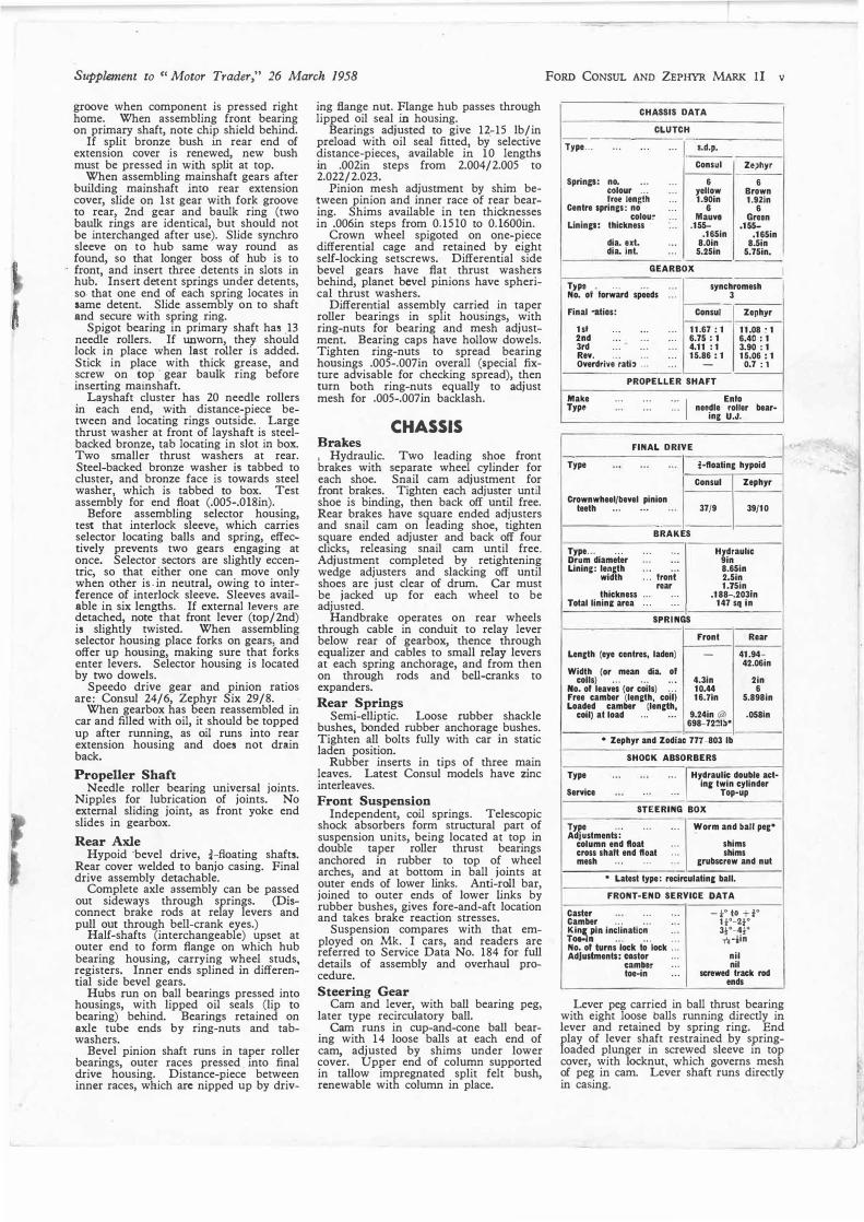
Bevel pinion shaft runs in taper roller bearings, outer races pressed into final drive housing. Distance-piece between inner races, which are nipped up by driv-
ing flange nut. Flange hub passes through lipped oil seal in housing.
Bearings adjusted to give 12_-15 lb/in preload with oil seal fitted, by selective distance-pieces, available in 10 lengths in .002in steps from 2.004/2.005 to 2.022/2.023.
Pinion mesh adjustment by shim between pinion and inner race of rear bearing. Shims available in ten thicknesses in .006in steps from 0.1510 to 0.1600in.
Crown wheel spigoted on one-piece differential cage and retained by eight self-locking setscrews. Differential side bevel gears have flat thrust washers behind, planet bevel pinions have spherical thrust washers.
Differential assembly carried in taper roller bearings in split housings, with ring-nuts for bearing and mesh adjustment. Bearing caps have hollow dowels. Tighten ring-nuts to spread bearing housings .005-.007in overall (special fixture advisable for checking spread), then turn both ring-nuts equally to adjust mesh for .005-.007in backlash.
CHASSIS Brakes , Hydraulic. Two leading shoe front brakes with separate wheel cylinder for each shoe. Snail cam adjustment for front brakes. Tighten each adjuster until shoe is binding, then back off until free. Rear brakes have square ended adjusters and snail cam on leading shoe, tighten square ended adjuster and back off four clicks, releasing snail cam until free. Adjustment completed by retightening wedge adjusters and slacking off until shoes are just clear of drum. Car must be jacked up for each wheel to be adjusted.
Handbrake operates on rear wheels through cable in conduit to relay lever below rear of gearbox, thence through equalizer and cables to small relay levers at each spring anchorage, and from then on through rods and bell-cranks to expanders.
Rear Springs Semi-elliptic. Loose rubber shackle
bushes, bonded rubber anchorage bushes. Tighten all bolts fully with car in static laden position.
Rubber inserts in tips of three main leaves. Latest Consul models have zinc interleaves.
Front Suspension Independent, coil springs. Telescopic
shock absorbers form structural part of suspension units, being located at top in double taper roller thrust bearings anchored in rubber to top of wheel arches, and at bottom in ball joints at outer ends of lower links. Anti-roll bar, joined to outer ends of lower links by rubber bushes, gives fore-and-aft location and takes brake reaction stresses.
Suspension compares with that employed on Mk. I cars, and readers are referred to Service Data No. 184 for full details of assembly and overhaul procedure.
Steering Gear Cam and lever, with ball bearing peg,
later type recirculatory ball. Cam runs in cup-and-cone ball bear
ing with 14 loose balls at each end of cam, adjusted by shims under lower cover. Upper end of column supported in tallow impregnated split felt bush, renewable with column in place.
FORD CONSUL AND ZEPHYR MARK lI v
CHASSIS DATA
CLUTCH --
Type ... ... .. . ... s.d.p .
Consul Ze)hyr
Sprinp: no. ... ... 6 6 colour ... yellow Brown free lengiti ... 1.90in 1.92in
Centre sprin&s: no ... 6 6
colour ... Mauve Green Unincs: thickness ... .155- .155-
.165in .165in dia. ext. ... 8.0in 8.5in dia. int. ... 5.25in 5.75in
GEARBOX
Type • ... . .. No. ol forward speeds ...
synchromesh 3
Final •alias: Consul Zephyr
1st ... ... . .. 11.67: 1 11.08 , 1 2nd ... ... . .. 6.75 : 1 6.40 : 1 3rd ... ... . .. 4.11 : 1 3.90: 1 Rev. ... 15.86 : 1 15.06 : 1 Overdriv8. ;ati, : : : ... - 0.7 : 1
PROPELLER SHAFT
Make ... ... ...
I Enfo
Type ... ... . .. needle roller bear-ing U.J.
FINAL DRIVE
Type
Crownwheel/bevel pinion teeth ... . . .
--
¾•floating hypoid
Consul Zephyr
37/9 39/10
BRAKES
Type... . .. Drum diameter Linin&: length
width
thickness Total linin& area
. .. . ..
... . ..
::: froni" rear
... ...
... . ..
Hydraulic 9in 8.65in 2.5in 1.75in
.188-.203in 147 sq in
SPRINGS
Front Rear
Length (eye centres, laden) - 41.94-42.06in
Width (or mean dia. ol coils) ... ... . .• 4.3in 2in
No. of leaves (or coils) ... 10.44 6 Free camber (len&th, coil) 16.Tln 5.898in Loaded camber (length,
coil) al load ... ... 9.24in (ciJ .058in 698-7221b•
• Zephyr and Zodiac 777-803 lb
SHOCK ABSORBERS
Type
Service
··· 1
Hydraulic double act-in& twin cylinder
... ..• Top-up
STEERING BOX
Type ... Adjustments:
. ..
column end float cross shaft end float mesh ... ...
. .. Worm and ball peg•
... shims
. .. shims
. .. grubscrew and nut
• Latest type: recirculatinc ball.
FRONT-END SERVICE DATA
Caster . .. . .. Camber ... ... . .• �C:.�t• in�linalio�- _ : : : No. of turns lock lo lock .. . Adjustments: castor .. .
camber .. .
toe-in .. .
-t•to+t• H0-2t0
3½0-4½0
n-iin
nil nil
screwed track rod ends
Lever peg carried in ball thrust bearing with eight loose balls running directly in lever and retained by spring ring. End play of lever shaft restrained .by springloaded plunger in screwed sleeve in top cover, with locknut, which governs mesh of peg in cam. Lever shaft runs directly in casing.
I
......
j

Vi FORD CONSUL AND ZEPHYR MARK II Supplement to "Motor Trader," 26 March 1958
Parts of the front and rear suspension assemblies, with below rear axle components and hub assembly and above left, steering box unit and linkages.

Supplement to "Motor Trader," 26 March, 1958 FORD CONSUL AND ZEPHYR MARK II vi
--·-------------------------,
Firinr ordtr (Consul) •.. (Zephyr) ••• . ..
Tappet clearance: (cold): ,nlel exhaust
Valve liming (no clearance):
l�l:l :r:a�� ::: :::exhaust opens... . .. exhaust closes ...
Standard ignition timing
Location ol timing mark ... Distri&ulor: type and service No. Advance range (dist. de&.):
centrif. ... . •.
vacuum
Advance starts (crank r.p.m.) .. . Max. advance (crank r.p.m.) .. .
Cam angle (percentage dwell) ...
Contact spring tension Contact set No. (Consul)
(Zephyr) Contact breaker gap .. . Condenser: capacity .. .
SLACK. RED lRACER
YELLOW. WHITE Tfl.ACEP. BLUE. YELLOW TRACER RED• WHITE TRACER
YELLOWBLACK lRACER
GREEN -l++t-ht+t+t-i
YELLOW. RED I RACER REDYELLOW lRACER
BLACK· 8lUE lRACER
BROWN. WHITE TR.ACEP.
MOWN
RED-WHllE
TUNE-UP DATA
1-2-4-3 1-5-3-6-2-4 .014in .014in
17° BTDC 51° ABDC 49° BBDC 19° ATDC 8° BTDC-H/C 4° BTDC-L/C Pulley & pointer Enlo
10°-12° at 4,000 r.p.m.
4°-6° at 4,000 r.p.m.
HC 4-cyl. 600-800 4,200 4,000-7,8 4,000 Consul H/C
& L/C 64-69 consul 55-60 Zephyr 18-22 oz EOTA-12162/C EOTA-12162/8 .014-.016in .18-.22 mid.
Plup: make ... type size .. . gap .. .
Carburetter: make type
ltllin&t: Choke .. . Main Jet .. . Power Jet .. . Idling jet .. . Progression jet
Accelerator pump Jets .. . High speed bleed .. .
Needle seating .. . Float level .. .
Air cleaner: make ... type (home) (export) .. .
Fuel pump: make .. . typo .. . pressure .. .
*Prior to Nov. 1956 Alter: Main 155 Power 110
Champion NB 14mm .032in Enfo downd,aught single venturi
Consul Zephyr
26 115 65 45 2x80 70 70
2mm
31 145• 107t 50 2x80 70 100•
16mm lrom lace of float chamber Enio oil wet oil bath Enlo mechanical 1 l·2½1b/sq in
High speed bleed 70
TRACER--�::::_-::i====r=====�=������E���g�����
FLASHER
ELECTRICAL TEST DATA
BATTERY Type .. . Voltage .. .
No. of plates Capacity
,pec. gravity: charged d'scharge:I
DYNAMO Type ... ... . .. Service No. ... . .. Rotation ;comm. end) ... Cut-in volts al r.p.m. . .. Max. output . . . .. Max. 1-everse current ...
Field resistance Brush tension
CONTROL BOX Service No. ... . .. Cut-out: cut-in voltage ... Regulator voltage: 10°C (50°F)
STARTER
2a'C (68"F) 30'C (86° F) 40°C (104°FI
Service No. ... . .. Rotation (comm. end) ... Lock torque (lb/It amps) Brush tension . .. . ..
COIL Type ... •.. ... . .. Service No. ... ... . .. Primary resistance (Lucas type) Primary resistance (Delco-Remy
lypt) ... . ..
lead acid 12
Consul Zephyr
9 9 45 ah 57 ah
1.27-1.285 1.110 72 amp/hr
shunt wound
clockw'se 13@ 964 228 walls 5 amps@ 12
volts 6.1 ohms 22-25 oz
EOTA 10505-D 12.7-13.3 volts 15.7-16.1 15.6-16.0 15.5-15.9 15.4-15.8
EOTA-11001·3 clockwiH: 9.6/380 30-40 oz
oil filled, 12v 100E-12024 3.2•3.4 ohms•
Secondary re•istance ..
(Lucas type) ... ... ... · ··
1 SecondarJ res'stance ...
(De!c·o
·•· Remy type)
4.15-4.55 ohms•
4700-4800 ohms•
5500-7100 ohms•
*Al 68°F,
ADDITIONAL ELECTRICAL DATA -----------
1,-·_M_o _d
_e_l _1
__ s_ e_rv_i_ce_N_o_._ Hoadlamps .. . ... All 204E-13005·B Side lamps . ... Consul 204E-13200-B
Zephyr 10/57 ... Zodiac 206E-13200-A Flasher Zephyr 12/56/ 10/57 206E-13200·C
Slop/tail lamps ··· 1
Consul E111•NC-2 Zephyr 206E•13407-A
Flasher ... Zodiac 208E·13407-B Reversing lamp . .. All 204E-15500 Number plate lamp All 204E-13550-A Starter solenoid switch All EOTTA-11450 Lighlinr switch ... All lOOE-11654-B Ignition switch . .. All 204E•11572-A Fog lamp switch ... All EOTTA-15224 Trafficator switch ... 206E-13341-B Flasher unit .. . .. . All 100E•13350-B Screenwiper ... ... All 204E-17500-A
Fuse box . . . . 2E-14.S25 Horns: high note ... All 204E-13802
} EOA-13802-B low note ... All 204E-13801
EOA-13801-E Horn relay ... ... All EOTTA-13842-A
Headlamps: dip left ... dip right vertical
dip Side lamps: standa,'d
flasher S!op/tail lamps:
Standard ... ... Flasher
Number plate'iamp ·.·.' Ignition ... . .. Oil warning lamp ... Panel lamps ... Interior lamp
flasher Beam and warning lamps
BULBS
1 Volt• I I tage . Waltage Cap --
12 42/36 Prelocus 12 42/36 Prefocus
12 42/38 Pre!ocus 12 6/21 SBC 12 6/21 SBC
21/6 SBC 12 12 21 sec 12 6 MCC 12 3 MES
12 3 MES
12 3 t2 off) MES
12 Fosloon
12 3 MES ----
FUSES
Accessories ... . . . . .. I I 2 x 35 amp
'

viii FORD CONSUL AND ZEPHYR MARK II Supplement to "Motor Trader," 26 March 1958
10
0
12
KEY TO MAINTENANCE DIAGRAM
DAILY 1. Radlator 2. Engine sump } check and top up
EVERY 1,000 MILES
5. Steerlnll, gear !: �==;�«:c�e
l 6. Battery 7. Brake and clutch fluid reservoir 8. Steering ball Joints (6)
check and
top up
JO. Gear change levers on steerinll, grease 9. Relay arm pivot (2)
} column (1) gun
11. Handbrake cables (2) 12. Propeller shaft universal joints (2)--oil
gun (S.A.E.140). 13. Distributor---0il shaft bearing, auto advance
and cootact breaker pivot, smear cam with petroleum jelly.
14. Fuel pump-dean filter and sediment bowl.
EVERY 5,000 MILES 15. Enll,ine sump -drain, flush and refill. 16. Engine oil filter-renew. 17 Gearbox
} 18: Rear axle dram, flush and reflU.
19. Front wheel l,u:,s -remove and repack with bearing grease.
20. Air cleaner (oil wet)-wash in petrol and re-oil.
21. Air cleaner (oil bath)-wash element in petrol, refill with engine oil.
22. Generator-a few drops of engine oil to oilhole In rear bearing boss.
23. Rear road sprinll,s--sprny with penetrating oil
24. Front suspension units } top up with shock
2o. Rear shock absorbers al>sorl>er fluid
DRAINING POINTS
Left : Shows radiator matrix drain tap situated in base plate, access from beneath. Right : Cylinder block drain tap at nearside rear of engine adjacent
to starter motor.
FILL-UP DATA
Pints Litres •Engine sump, Consul . .. 6 3.41
Zephyr ... 7 3.91 Gearbox ... ... 2½ 1.42 Rear axle : : : . . . 2½ 1.42 Coolln1 system: Consul ... 18 11.11
. .. 22 12.49 Zephyr Fual tank ... Ty,e pressun,s: · ··
. . . 10½ &all. 47.73
front and rear (Consul) 24-28 lb/ 1.68-1.97 sq in
(Zephyr) 24 lb/sq In leg/cm•
1.6 8 lc&/cm•
• 1½ pints for dry oil filte,.
GENERAL DATA
Wheelbase (Consul) . . .
(Zephyr) ...
Track: Front and rear (Con,ul) Front and rear (Zephyr)
Turninc circle (Consul) !Zephyr)
Ground clearance: !Consul ind Zephyr) •.• (Zodiac) ... . ..
Tyre size: Front and rear (Consul)
...
...
...
...
...
...
...
...
...
Front and rear (Zephyr and Zodiac) •.• ... . ..
Overall len!llh (without over-riders \Consul) . . . . ..
Overall .enEth (without over-riders) (Zep,r) . . . . ..
Overall width ( ephyr and Zodiac) Overall width (Consul) ... Overall height
iiionsuli"' ...
Weicht (kerb) ...
(Zephyr) ...
(Zodiac) ...
•Unladen.
8ft 8½in 8ft 11in
411 4.Sin 4ft Sin
3511 0in 3611 0in
&Jin 6 in
5.90-13
6.40-13
14lt 4¾in
14ft 10tln 5ft 91n lilt 8¾in lilt 2in•
2,5041D 2,6911b2,7381b
RECOMMENDED LUBRICANTS
Duckhams I Wakefield Esso Shell Mobil Vlitzol B.P.
Enll,ine: Summer and NOL 20 Castrolite Extra Motor X-100 20/20W Mobiloil Arctic New D.20 Energ:ol winter Oil 20W/30 SAE 20W
Gearbox, steering box ·NOL EP 80 Cast-rol Hypoy Expee Spirax 80 EP Mobilube Byex 80 Ener�ol (not automatic trans- Transi.mission Light Compound 80 GX 80 EP SAE 80 mission) Oil
Rear axle NOL Ca.strol BYJ)Oy Expee Spirax 90 EP l\lobilul.>e Vitapoid 90 Encrgol Bypoid 90 Gear Oil Compound 90 GX 90 EP SAE 90
Approved lubricants ofshnilar grades and S.A.E. ratings are also supplied by the following: BRITISH OIL & TURPENTINE CORPN., FINA PETROLEUM PRODUCTS LTD., GERM LUBRICANTS LTD., EDWARD JOY & SONS LTD., MANCHESTER OIL REFINERY (SALES) LTD., MORRIS & CO. (SHREWSBURY) LTD., REGENT OIL CO. LTD., STERNOL LTD.
Printed in Eni:land by Cornwall Press Lid., Paris Garden, London, S.E.l.
....
.•