Motor Technology Update - Motors & Drivesmotors-drives.com/wp-content/uploads/2014/07/Motor...Motor...
60
Motor Technology Update Brent McManis, P.E. Industry Engineering Manager Baldor Electric: A Member of the ABB Group
Transcript of Motor Technology Update - Motors & Drivesmotors-drives.com/wp-content/uploads/2014/07/Motor...Motor...

Motor Technology UpdateBrent McManis, P.E.
Industry Engineering ManagerBaldor Electric: A Member of the ABB Group

Motor Technology Update
§ Motor Efficiency Background/Rules/Regulation§ Motor Technology
› Induction› Laminated Frame› Permanent Magnet› Line Start PM› Synchronous Reluctance
ABB
§ 145,000 employees in about 100countries
§ $42 billion in revenue (2013)§ Formed in 1988 merger of Swiss
and Swedish engineeringcompanies
§ Predecessors founded in 1883and 1891
§ Publicly owned company withhead office in Switzerland

ABB – 5 Global Divisions
PowerProducts
PowerSystems
DiscreteAutomationand Motion
ProcessAutomation
36,000employees
20,000employees
29,000employees
28,000employees
Low VoltageProducts
31,000employees
§ Electricals, automation, controlsand instrumentation for powergeneration and industrial processes
§ Power transmission
§ Distribution solutions
§ Low-voltage products
§ Motors and drives
§ Intelligent building systems
§ Robots and robot systems
§ Services to improve customersproductivity and reliability
§ ABB’s portfolio covers:

Motor Technology Update
Motor Efficiency Background/Rules/Regulation
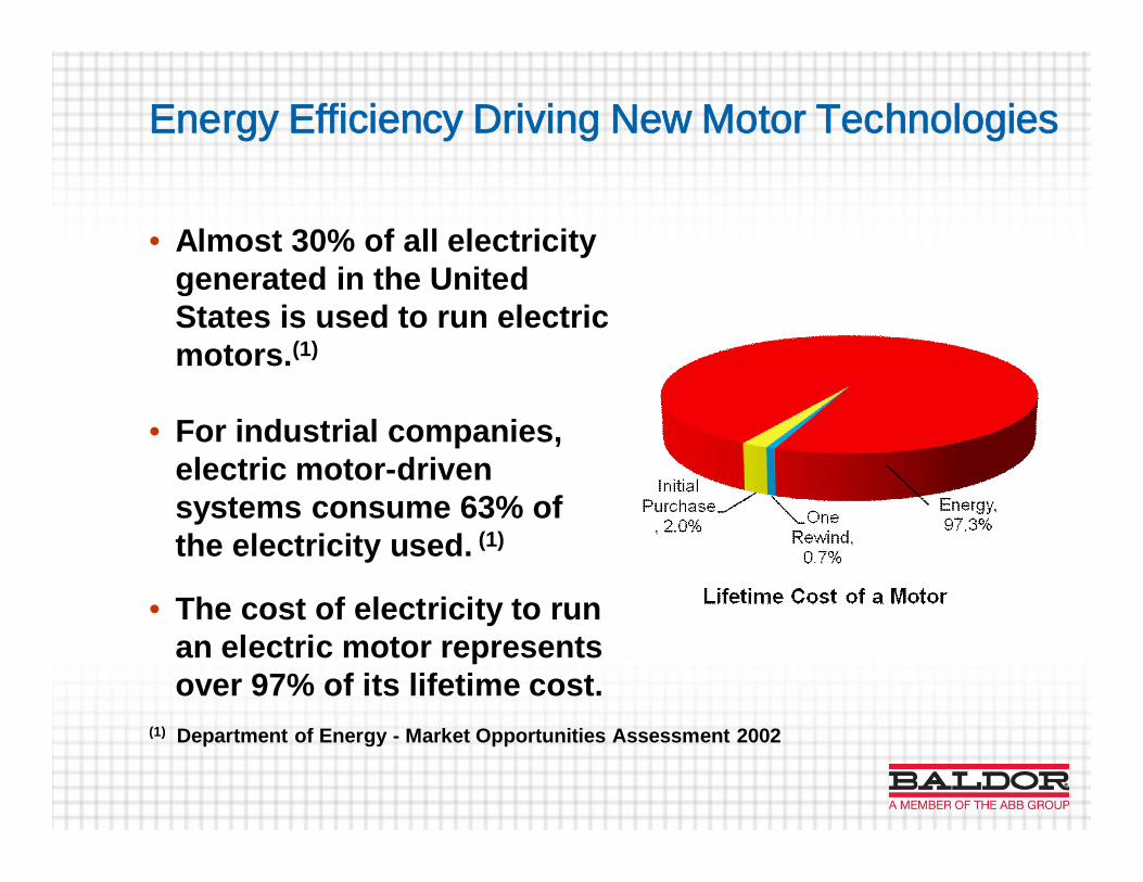
Energy Efficiency Driving New Motor Technologies
• Almost 30% of all electricitygenerated in the UnitedStates is used to run electricmotors.(1)
• For industrial companies,electric motor-drivensystems consume 63% ofthe electricity used. (1)
• The cost of electricity to runan electric motor representsover 97% of its lifetime cost.
(1) Department of Energy - Market Opportunities Assessment 2002
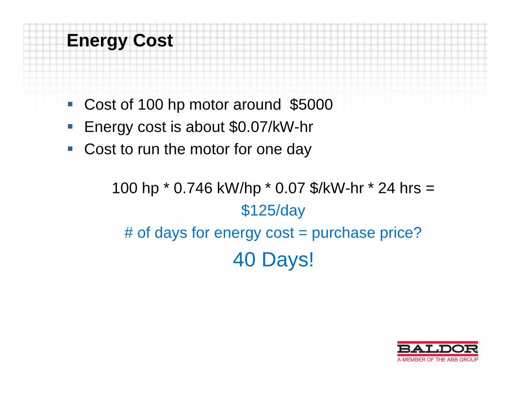
§ Cost of 100 hp motor around $5000§ Energy cost is about $0.07/kW-hr§ Cost to run the motor for one day
100 hp * 0.746 kW/hp * 0.07 $/kW-hr * 24 hrs =$125/day
# of days for energy cost = purchase price?
40 Days!
Energy Cost

Induction Motors
§ Workhorse of Industrial and Commercial Applications§ Motor efficiency regulated by US DOE, Canada - NRCan, EU
› EPAct effective 1997› EISA effective 2010› Integral Motor Rule effective May 2016› Small Motor Rule effective Mar 2015› EU at IE2 effective Jun 2011› EU at IE3 for 7.5-370 kW effective 2015› EU at IE3 for 0.75 – 370 kW effective 2017

NEMA, IE ….?
NEMA MG-1 IE-60034-10
EPACT Efficiency Table 12-11 IE-2
NEMA Premium Efficiency Table 12-12 IE-3
Super Premium Efficiency (proposed) TBD IE-4
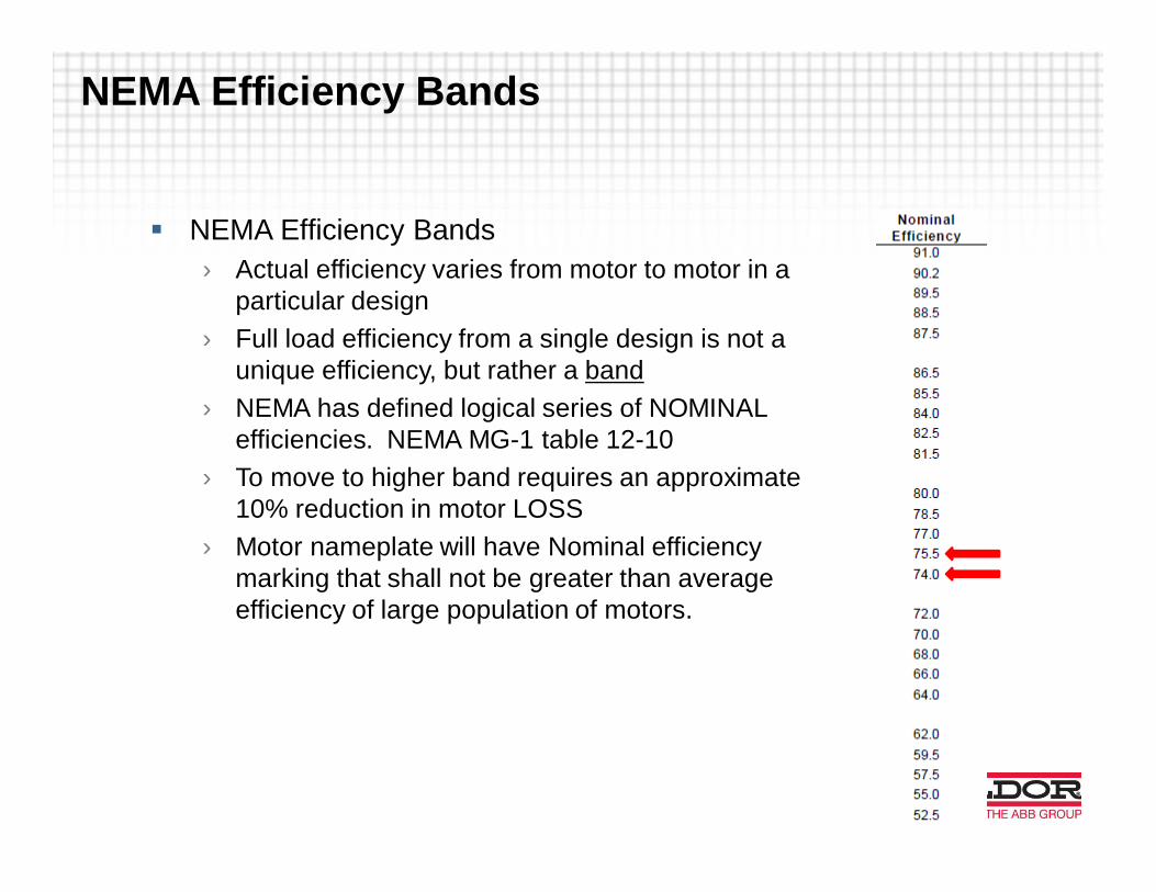
NEMA Efficiency Bands
§ NEMA Efficiency Bands› Actual efficiency varies from motor to motor in a
particular design› Full load efficiency from a single design is not a
unique efficiency, but rather a band› NEMA has defined logical series of NOMINAL
efficiencies. NEMA MG-1 table 12-10› To move to higher band requires an approximate
10% reduction in motor LOSS› Motor nameplate will have Nominal efficiency
marking that shall not be greater than averageefficiency of large population of motors.
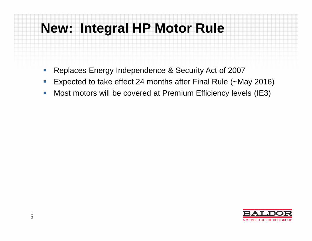
§ Replaces Energy Independence & Security Act of 2007§ Expected to take effect 24 months after Final Rule (~May 2016)§ Most motors will be covered at Premium Efficiency levels (IE3)
New: Integral HP Motor Rule
12
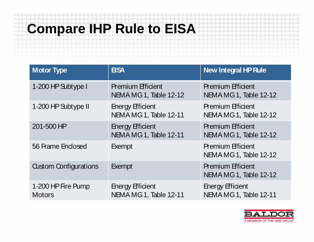
Motor Type EISA New Integral HP Rule
1-200 HP Subtype I Premium EfficientNEMA MG 1, Table 12-12
Premium EfficientNEMA MG 1, Table 12-12
1-200 HP Subtype II Energy EfficientNEMA MG 1, Table 12-11
Premium EfficientNEMA MG 1, Table 12-12
201-500 HP Energy EfficientNEMA MG 1, Table 12-11
Premium EfficientNEMA MG 1, Table 12-12
56 Frame Enclosed Exempt Premium EfficientNEMA MG 1, Table 12-12
Custom Configurations Exempt Premium EfficientNEMA MG 1, Table 12-12
1-200 HP Fire PumpMotors
Energy EfficientNEMA MG 1, Table 12-11
Energy EfficientNEMA MG 1, Table 12-11
Compare IHP Rule to EISA

Motors covered under IHP Rule
The motors regulated under expanded scope meet the following ninecharacteristics:1. Is a single speed motor,2. Is rated for continuous duty3. Squirrel cage rotor4. 3-Phase line power,5. Has 2-, 4-, 6-, or 8-pole configuration,6. Is rated 600 volts or less,7. Has a three or four-digit NEMA frame size (or IEC metric equivalent) or an
enclosed 56 NEMA frame size (or IEC metric equivalent),8. 1 – 500 HP9. NEMA design A, B or C or IEC design N or H electric motor

Motors added previously not coveredby EISA
§ What is covered:› NEMA Design A motors from
201-500 HP› Electric motors with moisture-
resistant windings, sealed orencapsulated windings
› Partial electric motors› Totally-enclosed non-
ventilated (TENV) electricmotors
› Immersible electric motors› Integral brake electric motors› Non-integral electric brake
motors
› Electric motors with non-standard endshields or flanges
› Electric motors with non-standard base or mountingfeet
› Electric motors with specialshafts
› Vertical hollow shaft electricmotors
› Vertical medium and highthrust solid shaft electricmotors
› Electric motors with sleevebearings
› Electric motors with thrustbearings
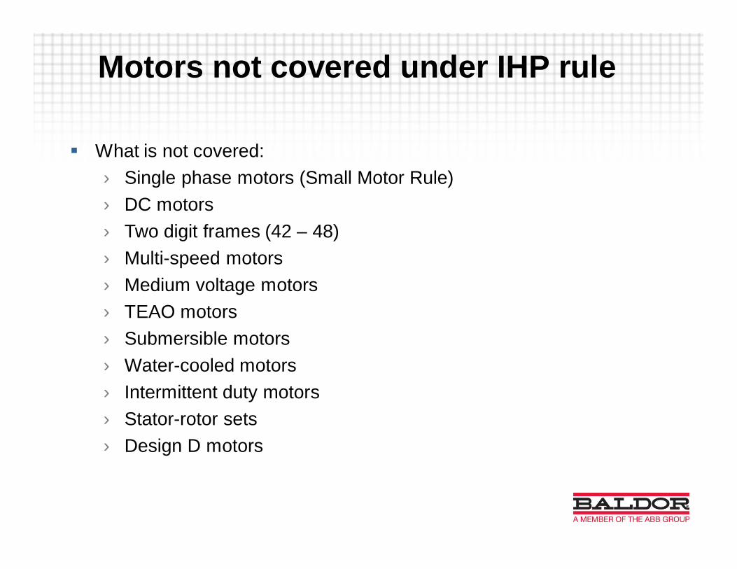
§ What is not covered:› Single phase motors (Small Motor Rule)› DC motors› Two digit frames (42 – 48)› Multi-speed motors› Medium voltage motors› TEAO motors› Submersible motors› Water-cooled motors› Intermittent duty motors› Stator-rotor sets› Design D motors
Motors not covered under IHP rule

What the New Rule Means
§ Motors manufacturers must begin building compliant motors by1 Jun 2016.
§ Existing inventory may be sold or used

§ Passed in 2010§ Covers ¼ - 3 HP 2, 4, 6 pole§ Open Drip Proof – General Purpose only§ 42, 48 , 56 Frame§ Both Single and Three Phase§ Specific DOE Average Efficiency Assignments (Not NEMA nominal)§ Effective March 9, 2015
New: Small Motor Rule

Improving Motor Efficiency:
§ Add more material› Longer core length› Slots more full of winding copper
§ If you want a 10% reduction in loss, add 10% more material§ Reduce fan size (trade off motor runs hotter)§ Maxed out on ability to increase efficiency above NEMA Premium®
efficiency§ Efficiencies beyond NEMA Premium® (IE3) will require different
technologies to stay in standard frame size.

84
86
88
90
92
94
96
98
1 10 100 1000
NEMA prem Eff/IE3
Horsepower
Perc
entE
ffici
ency
NEMA/IEC Nominal Efficiency Levels - TEFC, 1800 RPM
84
86
88
90
92
94
96
98
1 10 100 1000
NEMA prem Eff/IE3
IE4
Horsepower
Perc
entE
ffici
ency
NEMA/IEC Nominal Efficiency Levels - TEFC, 1800 RPM
84
86
88
90
92
94
96
98
1 10 100 1000
NEMA prem Eff/IE3
IE4
PE plus 4 bands
Horsepower
Perc
entE
ffici
ency
NEMA/IEC Nominal Efficiency Levels - TEFC, 1800 RPM
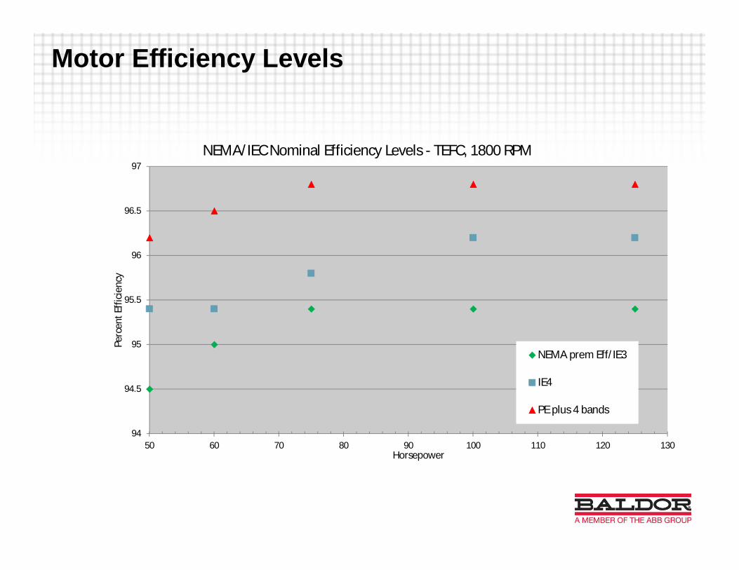
Motor Efficiency Levels
Motor Efficiency Levels
94
94.5
95
95.5
96
96.5
97
50 60 70 80 90 100 110 120 130
NEMA prem Eff/IE3
IE4
PE plus 4 bands
Horsepower
Perc
entE
ffici
ency
NEMA/IEC Nominal Efficiency Levels - TEFC, 1800 RPM

Motor Efficiency Levels
§ How do we get to IE4 and beyond?
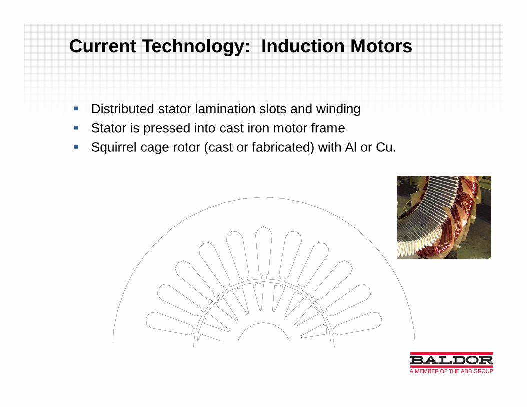
Current Technology: Induction Motors
§ Distributed stator lamination slots and winding§ Stator is pressed into cast iron motor frame§ Squirrel cage rotor (cast or fabricated) with Al or Cu.
RRR
RR R
T
T
T
S
S
ST
T
T
S
S
S
RR
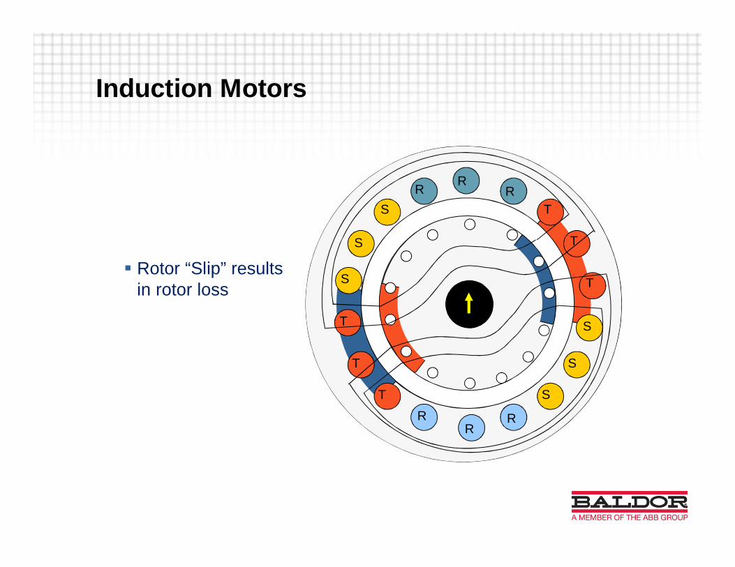
Induction Motors
§ Rotor “Slip” resultsin rotor loss

Laminated Frame Motors
• Developed in the 1980’s to replace DCwith AC Induction Motor
• Benefits of Laminated Frame• No cast frame• Channels for cooling air• Power dense
• Finned Laminated Frame• Developed in 2005• TEFC, TENV, TEBC• FOCUS ON POWER DENSITY• Up to 30% Increase in rating• Platform for Permanent Magnet Rotor
Baldor Proprietary
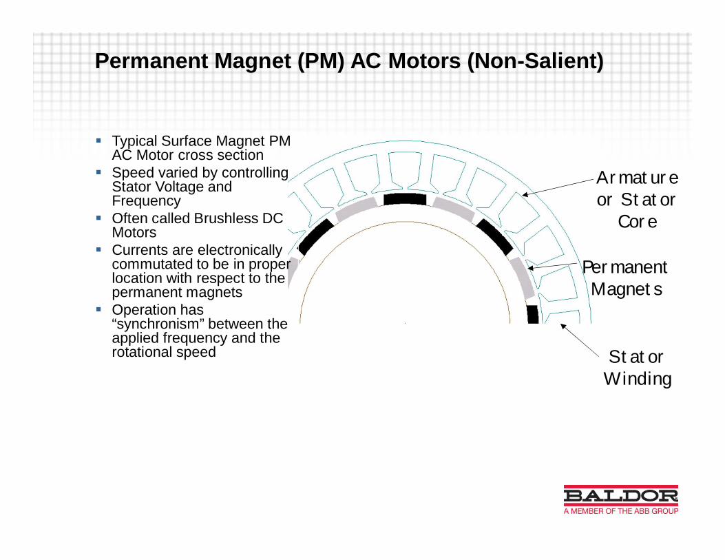
Permanent Magnet (PM) AC Motors (Non-Salient)
§ Typical Surface Magnet PMAC Motor cross section
§ Speed varied by controllingStator Voltage andFrequency
§ Often called Brushless DCMotors
§ Currents are electronicallycommutated to be in properlocation with respect to thepermanent magnets
§ Operation has“synchronism” between theapplied frequency and therotational speed
Armatureor Stator
Core
PermanentMagnets
StatorWinding
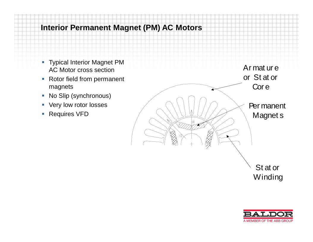
Interior Permanent Magnet (PM) AC Motors
§ Typical Interior Magnet PMAC Motor cross section
§ Rotor field from permanentmagnets
§ No Slip (synchronous)§ Very low rotor losses§ Requires VFD
Armatureor Stator
Core
PermanentMagnets
StatorWinding

PM Motor Configurations
Non-salient, Surface Magnet
Proprietary to Baldor / Reliance

PM Motor Configurations
Salient Pole, Interior Magnet
Proprietary to Baldor / Reliance

PM Motor comparison to IMFrame Type NEMA Cast Iron Laminated SteelRotor Type Induction Interior PMEnclosure TEFC TEFC TEBCHP @ 1750
RPM 20 100 100Frame Size 256T 405T FL2586
lbs/HP 16.25 11.60 5.32F.L. Amps 25.5 115 103.5F.L. Power
Factor 78.9% 86.4% 93.4%kW Losses 1.116 4.381 2.4
F.L. Efficiency 93.0% 94.5% 96.9%Rotor Inertia 2.42 lb-ft2 26.1 lb-ft2 4.9 lb-ft2
Temp Rise 80 C 80 C 77.6 C
Proprietary to Baldor / Reliance

Shaft Height Comparison
Proprietary to Baldor / Reliance

Application Specific PM Developments
§ Cooling Tower – Direct Drive Fan› Higher Reliability› Lower Operating Cost› Lower Environmental Impact
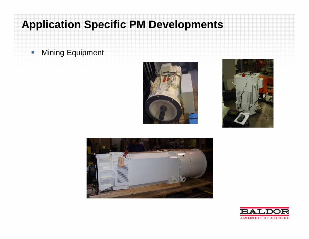
Application Specific PM Developments
§ Mining Equipment

Application Specific PM Developments
§ Blower for theme park ride› Compact Design› Higher Reliability› High Response

Application Specific PM Developments
§ Drill Rig Top drive motor

Application Specific PM Developments
§ Top drive motor› Greater Power Density› Higher Reliability› Lower Cost

Application Specific PM Developments
§ Top drive motor› Higher Power within a fixed envelope› Low Noise› Higher Reliability› Certification
• Ex e

Application Specific Developments
§ Vertical PM motor w/ Planetary Gearset for Low Speed HighVolume Pumping› Replaces Slow Speed High Pole Count Motors
• Single reduction planetary gear
• 8:1 Reduction
• 5,000,000 in-lbs output torque

PM Motors, the next generation
§ Past development as focused on power density and meeting specificapplication needs
§ Optimizing efficiency has not been primary goal§ PM designs require VFD with special control firmware§ What if application doesn’t need VFD?§ Can we use this technology to get to the next efficiency levels (IE4)?

PM Motor that can start as a normal induction motor“Line Start”; “Across the line”; “DOL”
PM Motors, the “New Approach”

MAGNETS
CAGE SLOTSCAGE SLOTS
Line Start PM Motors
Line Start PM Motors
§ Steady State Demonstrated Performance at 30 - 250 HP› Proof-of-Concept motors and prototypes designed, built, and tested
from 30 – 250 HP› Test rigs were built to accurately measure the efficiency› Test rigs were built to assess the starting and synchronization
capabilities

93
93.5
94
94.5
95
95.5
96
96.5
97
97.5
98
25 250
NEMA prem Eff/IE3
IE4
PE plus 4 bands
Line Start PM
Horsepower
Perc
entE
ffici
ency
NEMA/IEC Nominal Efficiency Levels - TEFC, 1800
Line Start PM Motor Efficiency
93
93.5
94
94.5
95
95.5
96
96.5
97
97.5
98
25 250
NEMA prem Eff/IE3
IE4
PE plus 4 bands
Line Start PM
Horsepower
Perc
entE
ffici
ency
NEMA/IEC Nominal Efficiency Levels - TEFC, 1800
93
93.5
94
94.5
95
95.5
96
96.5
97
97.5
98
25 250
NEMA prem Eff/IE3
IE4
PE plus 4 bands
Line Start PM
Horsepower
Perc
entE
ffici
ency
NEMA/IEC Nominal Efficiency Levels - TEFC, 1800
93
93.5
94
94.5
95
95.5
96
96.5
97
97.5
98
25 250
NEMA prem Eff/IE3
IE4
PE plus 4 bands
Line Start PM
Horsepower
Perc
entE
ffici
ency
NEMA/IEC Nominal Efficiency Levels - TEFC, 1800

Line Start PM - Too good to be true?
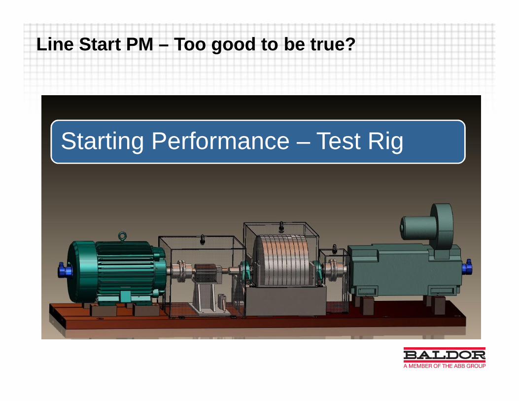
Line Start PM – Too good to be true?
Starting Performance – Test Rig
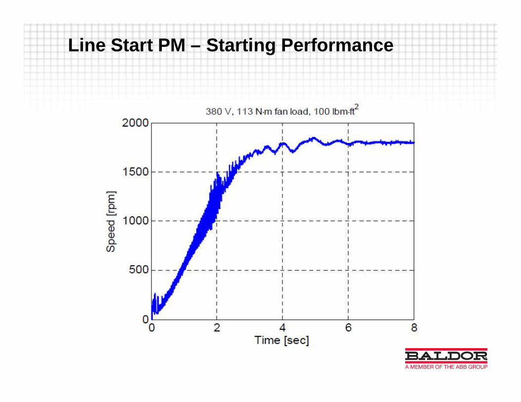
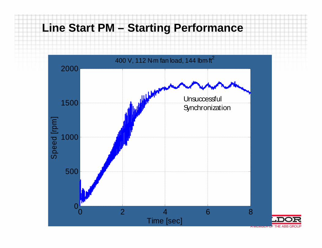
Line Start PM – Starting Performance
0 2 4 6 80
500
1000
1500
2000
Time [sec]
Spe
ed[rp
m]
400 V, 112 N×m fan load, 144 lbm×ft2
Line Start PM – Starting Performance
UnsuccessfulSynchronization

Motors can synchronize in the range of 20x their owninertia or about 25% of the equivalent NEMAinduction motor load wk2
Line Start PM – Starting Performance

Line Start PM – Starting Performance
§ For high inertia loads, soft start options are available

§ Demonstrated efficiencies jumped beyond IE4 levels with 4 – 8 NEMAefficiency band improvements beyond NEMA Premium / IE3
§ LSPM Motors enable leaps in energy efficiency§ Power factors also higher than induction motors§ Ability to run on simple inverters (V/Hz or “scalar mode”)§ Capability to start most (but not all loads)§ Torque pulsations during starting§ Dependent on high strength magnets§ Potential for magnet costs to drive costs up§ Need to account for lack of slip in applications
Line Start PM – Conclusions

“New” Technology - Synchronous Reluctance
§ Not a new idea (1923)§ No suitable starting method
available (VFD)§ Initial work with technology
could not demonstratesuperior torque performance
§ Advances in drive technologyand design have overcomeinitial obstacles

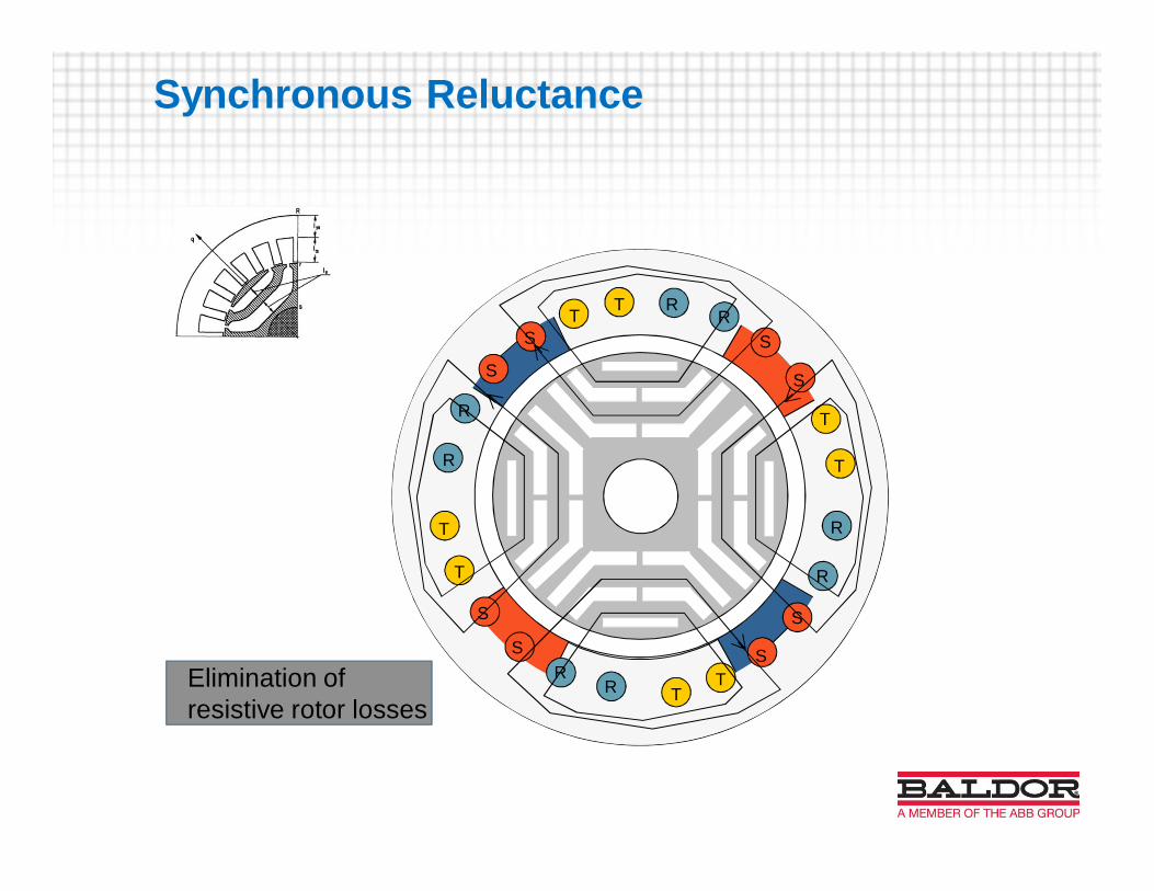
Synchronous Reluctance
§ Magnetic Reluctance is themagnetic equivalence toresistance
§ Rotor consist of one directionof least possible reluctance(d) and a perpendiculardirection (q) with a highreluctance
§ Torque is produced as therotor attempts to align it’smagnetically conductingdirection with the field.

Synchronous Reluctance
§ Distributed, symmetric stator laminationand winding (same as induction motor)
§ Rotor is simple design, no magnets orcage.
§ Designed to create areas of highreluctance
RR
S
S
T
T
TT
T
T
T T
S
SS
S
S
S
R
R
RR
R
R
Elimination ofresistive rotor losses
Synchronous Reluctance

Synchronous Reluctance - Performance
§ Comparison testing of “packaged” SynR motor/drive w/ IEC IE2 Inductionmotor/drive as function of speed.
83.0
84.0
85.0
86.0
87.0
88.0
89.0
90.0
91.0
92.0
93.0
94.0
500 700 900 1100 1300 1500 1700
IE4 SynRM
IE2 IM
Speed (RPM)
Effic
ienc
y(%
)
55 KW, 1500 RPM(Variable Torque loadcurve)

§ Demonstrated efficiencies up to IE 4 levels§ Simple rotor construction (no magnets or cages)§ Low temperature operation (no rotor losses)§ Low rotor inertia§ Technology can be optimized for power density or efficiency§ Requires a VFD (no line start)§ Power factor worse than IM or PM (may need bigger drive/cabling)
Synchronous Reluctance – Conclusions

Induction Lam. Frame IM Lam. Frame IPM Line Start PM SyncR
Simple Construction High Power density Higher Power density Very low rotor losses Very low rotor losses
Proven Technology Higher speeds Very low rotor losses Does not require VFD Lowest inertia
Industry Standard No frame = lower weight Lower weights Can run on standard VFD Simple rotor (cost)
Low Cost Could be designed tooptimize Eff
Could be designed tooptimize Eff
Higher Power Factor Lower weight
Efficiency gains at max Flexibility with framelength
Flexibility with framelength
Higher Efficiency (IE4and beyond)
Can be optimized for effor power density
Rotor Loss Frame size may notmatch NEMA standard
Magnet Cost Magnet Cost Cool Running
Low power density Rotor losses Loss of Magnetism Loss of Magnetism Requires VFD
May require specialinverter or feedback
Starting Torque Low Power Factor
Torque Ripple
New Motor Technology Comparison

§ Advances in motor designs, technology and materials are enablingmotor manufacturers to push motor efficiencies beyond current IE3,induction motor capabilities.
§ Line Start Permanent Magnet and Synchronous Reluctance are two“emerging” technologies that could be beneficial to the pump andfan industries.
§ QUESTIONS?
Motor Technology Update

Motor Technologies: Switched ReluctanceMotors
§ Typical SwitchedReluctance Motorcross section
§ Speed varied bycontrolling currentand frequency(current pulses)
§ Currents areelectronicallycommutated to be inproper slots withrespect to the rotorposition
StatorCore
Rotor Core
StatorWinding