Motor Repair Supplies Catalog
175
Transcript of Motor Repair Supplies Catalog

©Essex Group, Inc., 1998
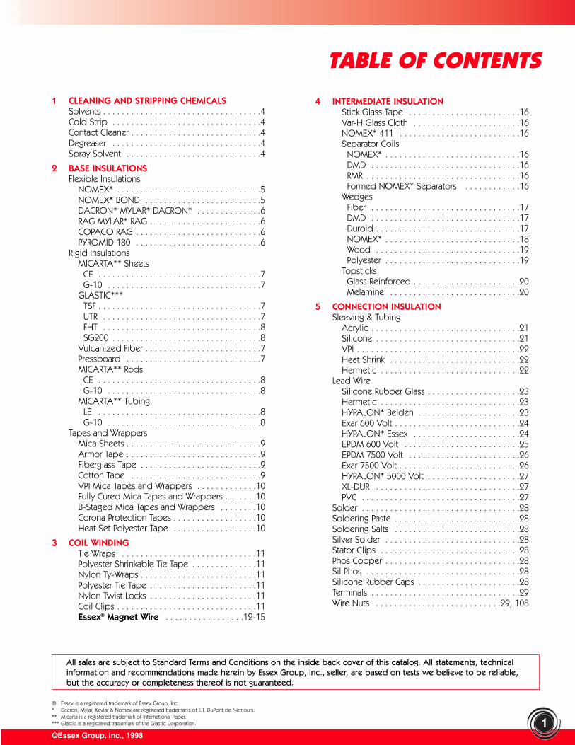
1 CLEANING AND STRIPPING CHEMICALSSolvents . . . . . . . . . . . . . . . . . . . . . . . . . . . . . . . . . .4Cold Strip . . . . . . . . . . . . . . . . . . . . . . . . . . . . . . . .4Contact Cleaner . . . . . . . . . . . . . . . . . . . . . . . . . . . .4Degreaser . . . . . . . . . . . . . . . . . . . . . . . . . . . . . . . .4Spray Solvent . . . . . . . . . . . . . . . . . . . . . . . . . . . . .4
2 BASE INSULATIONSFlexible Insulations
NOMEX* . . . . . . . . . . . . . . . . . . . . . . . . . . . . . . .5NOMEX* BOND . . . . . . . . . . . . . . . . . . . . . . . . .5DACRON* MYLAR* DACRON* . . . . . . . . . . . . . .6RAG MYLAR* RAG . . . . . . . . . . . . . . . . . . . . . . . .6COPACO RAG . . . . . . . . . . . . . . . . . . . . . . . . . . .6PYROMID 180 . . . . . . . . . . . . . . . . . . . . . . . . . . .6
Rigid InsulationsMICARTA** Sheets
CE . . . . . . . . . . . . . . . . . . . . . . . . . . . . . . . . . . .7G-10 . . . . . . . . . . . . . . . . . . . . . . . . . . . . . . . . .7
GLASTIC***TSF . . . . . . . . . . . . . . . . . . . . . . . . . . . . . . . . . . .7UTR . . . . . . . . . . . . . . . . . . . . . . . . . . . . . . . . . .7FHT . . . . . . . . . . . . . . . . . . . . . . . . . . . . . . . . . .8SG200 . . . . . . . . . . . . . . . . . . . . . . . . . . . . . . . .8
Vulcanized Fiber . . . . . . . . . . . . . . . . . . . . . . . . .7Pressboard . . . . . . . . . . . . . . . . . . . . . . . . . . . . .7MICARTA** Rods
CE . . . . . . . . . . . . . . . . . . . . . . . . . . . . . . . . . . .8G-10 . . . . . . . . . . . . . . . . . . . . . . . . . . . . . . . . .8
MICARTA** TubingLE . . . . . . . . . . . . . . . . . . . . . . . . . . . . . . . . . . .8G-10 . . . . . . . . . . . . . . . . . . . . . . . . . . . . . . . . .8
Tapes and WrappersMica Sheets . . . . . . . . . . . . . . . . . . . . . . . . . . . . .9Armor Tape . . . . . . . . . . . . . . . . . . . . . . . . . . . . .9Fiberglass Tape . . . . . . . . . . . . . . . . . . . . . . . . . .9Cotton Tape . . . . . . . . . . . . . . . . . . . . . . . . . . . .9VPI Mica Tapes and Wrappers . . . . . . . . . . . . .10Fully Cured Mica Tapes and Wrappers . . . . . . .10B-Staged Mica Tapes and Wrappers . . . . . . . .10Corona Protection Tapes . . . . . . . . . . . . . . . . . .10Heat Set Polyester Tape . . . . . . . . . . . . . . . . . .10
3 COIL WINDINGTie Wraps . . . . . . . . . . . . . . . . . . . . . . . . . . . . .11Polyester Shrinkable Tie Tape . . . . . . . . . . . . . .11Nylon Ty-Wraps . . . . . . . . . . . . . . . . . . . . . . . . .11Polyester Tie Tape . . . . . . . . . . . . . . . . . . . . . . .11Nylon Twist Locks . . . . . . . . . . . . . . . . . . . . . . .11Coil Clips . . . . . . . . . . . . . . . . . . . . . . . . . . . . . .11Essex® Magnet Wire . . . . . . . . . . . . . . . . .12-15
4 INTERMEDIATE INSULATIONStick Glass Tape . . . . . . . . . . . . . . . . . . . . . . . .16Var-H Glass Cloth . . . . . . . . . . . . . . . . . . . . . . .16NOMEX* 411 . . . . . . . . . . . . . . . . . . . . . . . . . .16Separator Coils
NOMEX* . . . . . . . . . . . . . . . . . . . . . . . . . . . . .16DMD . . . . . . . . . . . . . . . . . . . . . . . . . . . . . . . .16RMR . . . . . . . . . . . . . . . . . . . . . . . . . . . . . . . . .16Formed NOMEX* Separators . . . . . . . . . . . .16
WedgesFiber . . . . . . . . . . . . . . . . . . . . . . . . . . . . . . . .17DMD . . . . . . . . . . . . . . . . . . . . . . . . . . . . . . . .17Duroid . . . . . . . . . . . . . . . . . . . . . . . . . . . . . . .17NOMEX* . . . . . . . . . . . . . . . . . . . . . . . . . . . . .18Wood . . . . . . . . . . . . . . . . . . . . . . . . . . . . . . .19Polyester . . . . . . . . . . . . . . . . . . . . . . . . . . . . .19
TopsticksGlass Reinforced . . . . . . . . . . . . . . . . . . . . . . .20Melamine . . . . . . . . . . . . . . . . . . . . . . . . . . . .20
5 CONNECTION INSULATIONSleeving & Tubing
Acrylic . . . . . . . . . . . . . . . . . . . . . . . . . . . . . . . .21Silicone . . . . . . . . . . . . . . . . . . . . . . . . . . . . . . .21VPI . . . . . . . . . . . . . . . . . . . . . . . . . . . . . . . . . . .22Heat Shrink . . . . . . . . . . . . . . . . . . . . . . . . . . . .22Hermetic . . . . . . . . . . . . . . . . . . . . . . . . . . . . . .22
Lead WireSilicone Rubber Glass . . . . . . . . . . . . . . . . . . . .23Hermetic . . . . . . . . . . . . . . . . . . . . . . . . . . . . . .23HYPALON* Belden . . . . . . . . . . . . . . . . . . . . . .23Exar 600 Volt . . . . . . . . . . . . . . . . . . . . . . . . . . .24HYPALON* Essex . . . . . . . . . . . . . . . . . . . . . . .24EPDM 600 Volt . . . . . . . . . . . . . . . . . . . . . . . . .25EPDM 7500 Volt . . . . . . . . . . . . . . . . . . . . . . . .26Exar 7500 Volt . . . . . . . . . . . . . . . . . . . . . . . . . .26HYPALON* 5000 Volt . . . . . . . . . . . . . . . . . . . .27XL-DUR . . . . . . . . . . . . . . . . . . . . . . . . . . . . . . .27PVC . . . . . . . . . . . . . . . . . . . . . . . . . . . . . . . . . .27
Solder . . . . . . . . . . . . . . . . . . . . . . . . . . . . . . . . . .28Soldering Paste . . . . . . . . . . . . . . . . . . . . . . . . . . .28Soldering Salts . . . . . . . . . . . . . . . . . . . . . . . . . . .28Silver Solder . . . . . . . . . . . . . . . . . . . . . . . . . . . . .28Stator Clips . . . . . . . . . . . . . . . . . . . . . . . . . . . . . .28Phos Copper . . . . . . . . . . . . . . . . . . . . . . . . . . . . .28Sil Phos . . . . . . . . . . . . . . . . . . . . . . . . . . . . . . . . .28Silicone Rubber Caps . . . . . . . . . . . . . . . . . . . . . .28Terminals . . . . . . . . . . . . . . . . . . . . . . . . . . . . . . . .29Wire Nuts . . . . . . . . . . . . . . . . . . . . . . . . . . .29, 108
TABLE OF CONTENTS
1
® Essex is a registered trademark of Essex Group, Inc.* Dacron, Mylar, Kevlar & Nomex are registered trademarks of E.I. DuPont de Nemours.** Micarta is a registered trademark of International Paper.*** Glastic is a registered trademark of the Glastic Corporation.
All sales are subject to Standard Terms and Conditions on the inside back cover of this catalog. All statements, technicalinformation and recommendations made herein by Essex Group, Inc., seller, are based on tests we believe to be reliable,but the accuracy or completeness thereof is not guaranteed.
©Essex Group, Inc., 1998
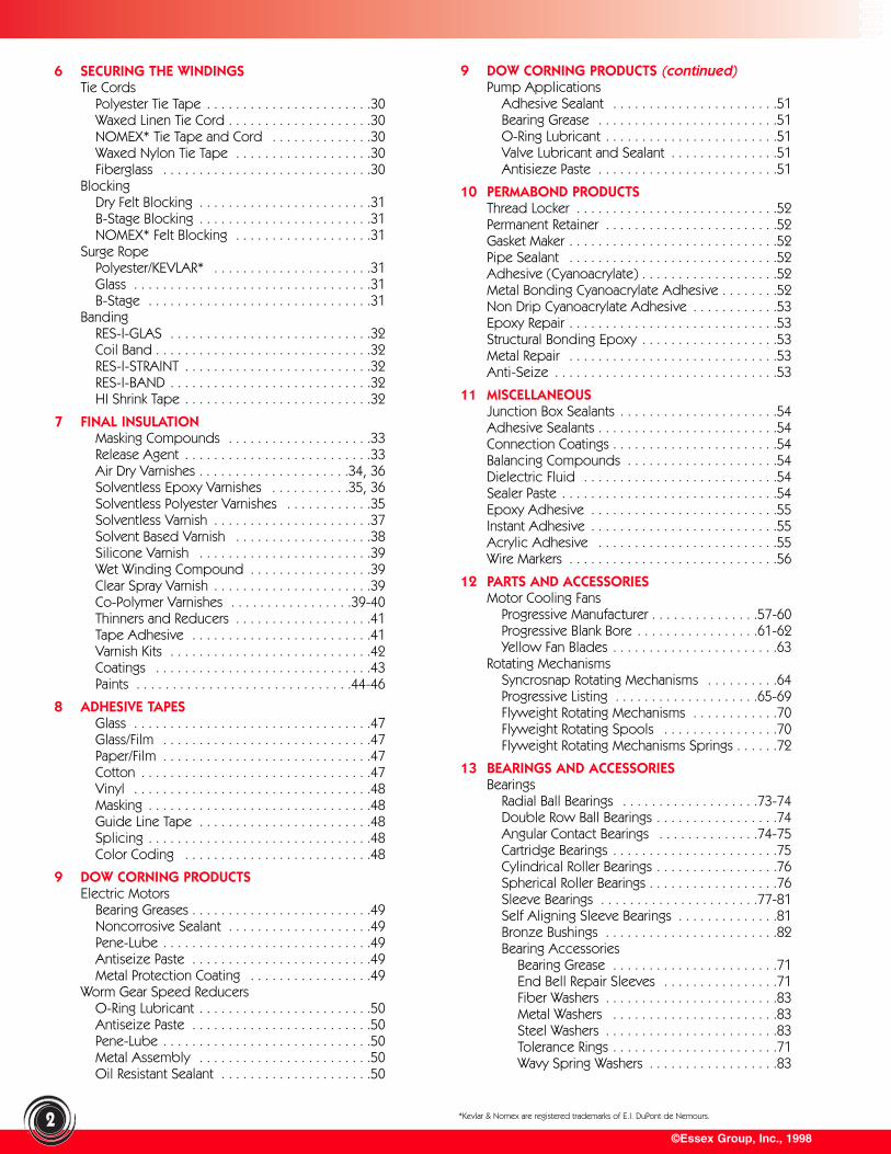
6 SECURING THE WINDINGSTie Cords
Polyester Tie Tape . . . . . . . . . . . . . . . . . . . . . . .30Waxed Linen Tie Cord . . . . . . . . . . . . . . . . . . . .30NOMEX* Tie Tape and Cord . . . . . . . . . . . . . .30Waxed Nylon Tie Tape . . . . . . . . . . . . . . . . . . .30Fiberglass . . . . . . . . . . . . . . . . . . . . . . . . . . . . .30
BlockingDry Felt Blocking . . . . . . . . . . . . . . . . . . . . . . . .31B-Stage Blocking . . . . . . . . . . . . . . . . . . . . . . . .31NOMEX* Felt Blocking . . . . . . . . . . . . . . . . . . .31
Surge RopePolyester/KEVLAR* . . . . . . . . . . . . . . . . . . . . . .31Glass . . . . . . . . . . . . . . . . . . . . . . . . . . . . . . . . .31B-Stage . . . . . . . . . . . . . . . . . . . . . . . . . . . . . . .31
BandingRES-I-GLAS . . . . . . . . . . . . . . . . . . . . . . . . . . . .32Coil Band . . . . . . . . . . . . . . . . . . . . . . . . . . . . . .32RES-I-STRAINT . . . . . . . . . . . . . . . . . . . . . . . . . .32RES-I-BAND . . . . . . . . . . . . . . . . . . . . . . . . . . . .32HI Shrink Tape . . . . . . . . . . . . . . . . . . . . . . . . . .32
7 FINAL INSULATIONMasking Compounds . . . . . . . . . . . . . . . . . . . .33Release Agent . . . . . . . . . . . . . . . . . . . . . . . . . .33Air Dry Varnishes . . . . . . . . . . . . . . . . . . . . .34, 36Solventless Epoxy Varnishes . . . . . . . . . . .35, 36Solventless Polyester Varnishes . . . . . . . . . . . .35Solventless Varnish . . . . . . . . . . . . . . . . . . . . . .37Solvent Based Varnish . . . . . . . . . . . . . . . . . . .38Silicone Varnish . . . . . . . . . . . . . . . . . . . . . . . .39Wet Winding Compound . . . . . . . . . . . . . . . . .39Clear Spray Varnish . . . . . . . . . . . . . . . . . . . . . .39Co-Polymer Varnishes . . . . . . . . . . . . . . . . .39-40Thinners and Reducers . . . . . . . . . . . . . . . . . . .41Tape Adhesive . . . . . . . . . . . . . . . . . . . . . . . . .41Varnish Kits . . . . . . . . . . . . . . . . . . . . . . . . . . . .42Coatings . . . . . . . . . . . . . . . . . . . . . . . . . . . . . .43Paints . . . . . . . . . . . . . . . . . . . . . . . . . . . . . .44-46
8 ADHESIVE TAPESGlass . . . . . . . . . . . . . . . . . . . . . . . . . . . . . . . . .47Glass/Film . . . . . . . . . . . . . . . . . . . . . . . . . . . . .47Paper/Film . . . . . . . . . . . . . . . . . . . . . . . . . . . . .47Cotton . . . . . . . . . . . . . . . . . . . . . . . . . . . . . . . .47Vinyl . . . . . . . . . . . . . . . . . . . . . . . . . . . . . . . . .48Masking . . . . . . . . . . . . . . . . . . . . . . . . . . . . . . .48Guide Line Tape . . . . . . . . . . . . . . . . . . . . . . . .48Splicing . . . . . . . . . . . . . . . . . . . . . . . . . . . . . . .48Color Coding . . . . . . . . . . . . . . . . . . . . . . . . . .48
9 DOW CORNING PRODUCTSElectric Motors
Bearing Greases . . . . . . . . . . . . . . . . . . . . . . . . .49Noncorrosive Sealant . . . . . . . . . . . . . . . . . . . .49Pene-Lube . . . . . . . . . . . . . . . . . . . . . . . . . . . . .49Antiseize Paste . . . . . . . . . . . . . . . . . . . . . . . . .49Metal Protection Coating . . . . . . . . . . . . . . . . .49
Worm Gear Speed ReducersO-Ring Lubricant . . . . . . . . . . . . . . . . . . . . . . . .50Antiseize Paste . . . . . . . . . . . . . . . . . . . . . . . . .50Pene-Lube . . . . . . . . . . . . . . . . . . . . . . . . . . . . .50Metal Assembly . . . . . . . . . . . . . . . . . . . . . . . .50Oil Resistant Sealant . . . . . . . . . . . . . . . . . . . . .50
9 DOW CORNING PRODUCTS (continued)Pump Applications
Adhesive Sealant . . . . . . . . . . . . . . . . . . . . . . .51Bearing Grease . . . . . . . . . . . . . . . . . . . . . . . . .51O-Ring Lubricant . . . . . . . . . . . . . . . . . . . . . . . .51Valve Lubricant and Sealant . . . . . . . . . . . . . . .51Antisieze Paste . . . . . . . . . . . . . . . . . . . . . . . . .51
10 PERMABOND PRODUCTSThread Locker . . . . . . . . . . . . . . . . . . . . . . . . . . . .52Permanent Retainer . . . . . . . . . . . . . . . . . . . . . . . .52Gasket Maker . . . . . . . . . . . . . . . . . . . . . . . . . . . . .52Pipe Sealant . . . . . . . . . . . . . . . . . . . . . . . . . . . . .52Adhesive (Cyanoacrylate) . . . . . . . . . . . . . . . . . . .52Metal Bonding Cyanoacrylate Adhesive . . . . . . . .52Non Drip Cyanoacrylate Adhesive . . . . . . . . . . . .53Epoxy Repair . . . . . . . . . . . . . . . . . . . . . . . . . . . . .53Structural Bonding Epoxy . . . . . . . . . . . . . . . . . . .53Metal Repair . . . . . . . . . . . . . . . . . . . . . . . . . . . . .53Anti-Seize . . . . . . . . . . . . . . . . . . . . . . . . . . . . . . .53
11 MISCELLANEOUSJunction Box Sealants . . . . . . . . . . . . . . . . . . . . . .54Adhesive Sealants . . . . . . . . . . . . . . . . . . . . . . . . .54Connection Coatings . . . . . . . . . . . . . . . . . . . . . . .54Balancing Compounds . . . . . . . . . . . . . . . . . . . . .54Dielectric Fluid . . . . . . . . . . . . . . . . . . . . . . . . . . .54Sealer Paste . . . . . . . . . . . . . . . . . . . . . . . . . . . . . .54Epoxy Adhesive . . . . . . . . . . . . . . . . . . . . . . . . . .55Instant Adhesive . . . . . . . . . . . . . . . . . . . . . . . . . .55Acrylic Adhesive . . . . . . . . . . . . . . . . . . . . . . . . .55Wire Markers . . . . . . . . . . . . . . . . . . . . . . . . . . . . .56
12 PARTS AND ACCESSORIESMotor Cooling Fans
Progressive Manufacturer . . . . . . . . . . . . . . .57-60Progressive Blank Bore . . . . . . . . . . . . . . . . .61-62Yellow Fan Blades . . . . . . . . . . . . . . . . . . . . . . .63
Rotating MechanismsSyncrosnap Rotating Mechanisms . . . . . . . . . .64Progressive Listing . . . . . . . . . . . . . . . . . . . .65-69Flyweight Rotating Mechanisms . . . . . . . . . . . .70Flyweight Rotating Spools . . . . . . . . . . . . . . . .70Flyweight Rotating Mechanisms Springs . . . . . .72
13 BEARINGS AND ACCESSORIESBearings
Radial Ball Bearings . . . . . . . . . . . . . . . . . . .73-74Double Row Ball Bearings . . . . . . . . . . . . . . . . .74Angular Contact Bearings . . . . . . . . . . . . . .74-75Cartridge Bearings . . . . . . . . . . . . . . . . . . . . . . .75Cylindrical Roller Bearings . . . . . . . . . . . . . . . . .76Spherical Roller Bearings . . . . . . . . . . . . . . . . . .76Sleeve Bearings . . . . . . . . . . . . . . . . . . . . . .77-81Self Aligning Sleeve Bearings . . . . . . . . . . . . . .81Bronze Bushings . . . . . . . . . . . . . . . . . . . . . . . .82Bearing Accessories
Bearing Grease . . . . . . . . . . . . . . . . . . . . . . .71End Bell Repair Sleeves . . . . . . . . . . . . . . . .71Fiber Washers . . . . . . . . . . . . . . . . . . . . . . . .83Metal Washers . . . . . . . . . . . . . . . . . . . . . . .83Steel Washers . . . . . . . . . . . . . . . . . . . . . . . .83Tolerance Rings . . . . . . . . . . . . . . . . . . . . . . .71Wavy Spring Washers . . . . . . . . . . . . . . . . . .83
2 *Kevlar & Nomex are registered trademarks of E.I. DuPont de Nemours.
©Essex Group, Inc., 1998
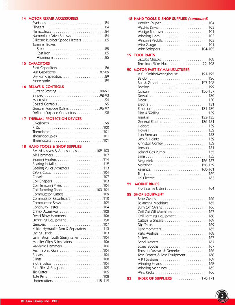
14 MOTOR REPAIR ACCESSORIESEyebolts . . . . . . . . . . . . . . . . . . . . . . . . . . . . . .84Flingers . . . . . . . . . . . . . . . . . . . . . . . . . . . . . . .84Nameplates . . . . . . . . . . . . . . . . . . . . . . . . . . . .84Nameplate Drive Screws . . . . . . . . . . . . . . . . .84Silicone Rubber Space Heaters . . . . . . . . . . . .85Terminal Boxes
Steel . . . . . . . . . . . . . . . . . . . . . . . . . . . . . . .85Cast Iron . . . . . . . . . . . . . . . . . . . . . . . . . . . .85Aluminum . . . . . . . . . . . . . . . . . . . . . . . . . . .85
15 CAPACITORSStart Capacitors . . . . . . . . . . . . . . . . . . . . . . . . .86Run Capacitors . . . . . . . . . . . . . . . . . . . . . . .87-89Dry Run Capacitors . . . . . . . . . . . . . . . . . . . . . .89Accessories . . . . . . . . . . . . . . . . . . . . . . . . . . .89
16 RELAYS & CONTROLSCurrent Starting . . . . . . . . . . . . . . . . . . . . . .90-91Sinpac . . . . . . . . . . . . . . . . . . . . . . . . . . . . .92-93Macrostart . . . . . . . . . . . . . . . . . . . . . . . . . . . . .94Speed Controls . . . . . . . . . . . . . . . . . . . . . . . . .95General Purpose Relays . . . . . . . . . . . . . . . .96-97Definite Purpose Contactors . . . . . . . . . . . . . . .98
17 THERMAL PROTECTION DEVICESOverloads . . . . . . . . . . . . . . . . . . . . . . . . . . . . .99RTDs . . . . . . . . . . . . . . . . . . . . . . . . . . . . . . . .100Thermistors . . . . . . . . . . . . . . . . . . . . . . . . . . .101Thermocouples . . . . . . . . . . . . . . . . . . . . . . . .101Thermostats . . . . . . . . . . . . . . . . . . . . . . . . . . .101
18 HAND TOOLS & SHOP SUPPLIES3M Abrasives & Accessories . . . . . . . . . .102-103Air Hammers . . . . . . . . . . . . . . . . . . . . . . . . . .107Bearing Heaters . . . . . . . . . . . . . . . . . . . . . . . .114Bearing Installers . . . . . . . . . . . . . . . . . . . . . . .112Bearing Puller Adapters . . . . . . . . . . . . . . . . .113Cable Cutter . . . . . . . . . . . . . . . . . . . . . . . . . .104Chisels . . . . . . . . . . . . . . . . . . . . . . . . . . . . . . .107Coil Shapers . . . . . . . . . . . . . . . . . . . . . . . . . .103Coil Tamping Pliers . . . . . . . . . . . . . . . . . . . . .104Coil Tamping Tools . . . . . . . . . . . . . . . . .103-104Commutator Cutters . . . . . . . . . . . . . . . . . . . .109Commutator Resurfacers . . . . . . . . . . . . . . . . .110Commutator Saws . . . . . . . . . . . . . . . . . . . . .109Continuity Tester . . . . . . . . . . . . . . . . . . . . . . .104Cratex Abrasives . . . . . . . . . . . . . . . . . . . . . . .102Dead Blow Hammers . . . . . . . . . . . . . . . . . . .106Dereeling Equipment . . . . . . . . . . . . . . . . . . .120Grinders . . . . . . . . . . . . . . . . . . . . . . . . . . . . .107Kukko Hydraulic Ram & Separators . . . . . . . . .113Lacing Hook . . . . . . . . . . . . . . . . . . . . . . . . . .103Lamination Tooth Straightener . . . . . . . . . . . .104Mueller Clips & Insulators . . . . . . . . . . . . . . . .106Rawhide Hammers . . . . . . . . . . . . . . . . . . . . .106Resin Spray Gun . . . . . . . . . . . . . . . . . . . . . . .104Shears . . . . . . . . . . . . . . . . . . . . . . . . . . . . . . .104Slings . . . . . . . . . . . . . . . . . . . . . . . . . . . . . . . .108Slot Brushes . . . . . . . . . . . . . . . . . . . . . . . . . .104Slot Files & Scrapers . . . . . . . . . . . . . . . . . . . .109Tie Cutter . . . . . . . . . . . . . . . . . . . . . . . . . . . . .105Tote Pans . . . . . . . . . . . . . . . . . . . . . . . . . . . . .108Undercutters . . . . . . . . . . . . . . . . . . . . . .115-119
18 HAND TOOLS & SHOP SUPPLIES (continued)Vernier Caliper . . . . . . . . . . . . . . . . . . . . . . . .104Wedge Driver . . . . . . . . . . . . . . . . . . . . . . . . .103Wedge Remover . . . . . . . . . . . . . . . . . . . . . . .104Winding Horn . . . . . . . . . . . . . . . . . . . . . . . . .103Winding Paddle . . . . . . . . . . . . . . . . . . . . . . .103Wire Gauge . . . . . . . . . . . . . . . . . . . . . . . . . . .104Wire Strippers . . . . . . . . . . . . . . . . . . . . .104-105
19 TOOL PARTSJacobs Chucks . . . . . . . . . . . . . . . . . . . . . . . .108Terminals Wire Nuts . . . . . . . . . . . . . . . . .29, 108
20 MOTOR PART BY MANUFACTURERA.O. Smith/Westinghouse . . . . . . . . . . . .121-125Baldor . . . . . . . . . . . . . . . . . . . . . . . . . . . . . . .126Bell & Gossett . . . . . . . . . . . . . . . . . . . . .127-128Bodine . . . . . . . . . . . . . . . . . . . . . . . . . . . . . .129Century . . . . . . . . . . . . . . . . . . . . . . . . . .156-157Dewalt . . . . . . . . . . . . . . . . . . . . . . . . . . . . . . .130Doerr . . . . . . . . . . . . . . . . . . . . . . . . . . . . . . . .130Electra . . . . . . . . . . . . . . . . . . . . . . . . . . . . . . .131Emerson . . . . . . . . . . . . . . . . . . . . . . . . . .131-132Flint & Walling . . . . . . . . . . . . . . . . . . . . . . . . .132Franklin . . . . . . . . . . . . . . . . . . . . . . . . . . .133-135General Electric . . . . . . . . . . . . . . . . . . . .136-151Hobart . . . . . . . . . . . . . . . . . . . . . . . . . . . . . . .152Howell . . . . . . . . . . . . . . . . . . . . . . . . . . . . . .152Iron Fireman . . . . . . . . . . . . . . . . . . . . . . . . . .153Jack & Heintz . . . . . . . . . . . . . . . . . . . . . . . . .152Kingston Conley . . . . . . . . . . . . . . . . . . . . . . .152Leeson . . . . . . . . . . . . . . . . . . . . . . . . . . . . . . .154Leland Gas Pump . . . . . . . . . . . . . . . . . . . . . .155Lima . . . . . . . . . . . . . . . . . . . . . . . . . . . . . . . . .155Magnetek . . . . . . . . . . . . . . . . . . . . . . . . .156-157Marathon . . . . . . . . . . . . . . . . . . . . . . . . .158-159Reliance . . . . . . . . . . . . . . . . . . . . . . . . . .160-161Torq . . . . . . . . . . . . . . . . . . . . . . . . . . . . . . . . .162US Electric . . . . . . . . . . . . . . . . . . . . . . . . . . . .163
21 MOUNT RINGSProgressive Listing . . . . . . . . . . . . . . . . . . . . . .164
22 SHOP EQUIPMENTBake Ovens . . . . . . . . . . . . . . . . . . . . . . . . . . .166Balancing Machines . . . . . . . . . . . . . . . . . . . .165Burn Off Ovens . . . . . . . . . . . . . . . . . . . . . . . .166Coil Cut Off Machines . . . . . . . . . . . . . . . . . . .167Coil Forming Equipment . . . . . . . . . . . . . . . . .168Cutters & Shears . . . . . . . . . . . . . . . . . . . . . . .169Dip Tanks . . . . . . . . . . . . . . . . . . . . . . . . . . . . .169Dynamometers . . . . . . . . . . . . . . . . . . . . . . . .165Parts Washers . . . . . . . . . . . . . . . . . . . . . . . . .168Pullers . . . . . . . . . . . . . . . . . . . . . . . . . . . . . . .167Sand Blasters . . . . . . . . . . . . . . . . . . . . . . . . . .167Spray Booths . . . . . . . . . . . . . . . . . . . . . . . . . .167Tension Devises & Dereelers . . . . . . . . . . . . . .166Test Centers & Test Equipment . . . . . . . . . . . .168V P I Systems . . . . . . . . . . . . . . . . . . . . . . . . . .169Winding Heads . . . . . . . . . . . . . . . . . . . . . . . .165Winding Machines . . . . . . . . . . . . . . . . . . . . .165Wire Racks . . . . . . . . . . . . . . . . . . . . . . . . . . . .166
23 INDEX OF SUPPLIERS . . . . . . . . . . . . . . .170-171
3
©Essex Group, Inc., 1998
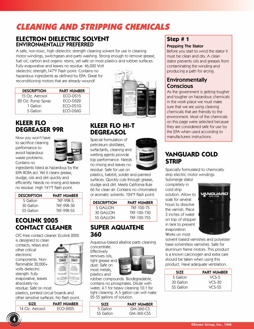
CLEANING AND STRIPPING CHEMICALSELECTRON DIELECTRIC SOLVENTENVIRONMENTALLY PREFERREDA safe, non-toxic, high dielectric strength cleaning solvent for use in cleaningmotor windings, switchgears and parts washing. Strong enough to remove grease,fuel oil, carbon and organic resins, yet safe on most plastics and rubber surfaces.Fully evaporative and leaves no residue. 46,000 Voltdielectric strength,147°F Flash point. Contains nohazardous ingredients as defined by EPA. Great forreconditioning motors that are already wound!
Step # 1Prepping The StatorBefore you start to wind the stator itmust be clean and dry. A cleanstator prevents oils and greases fromcontaminating the winding andproducing a path for arcing.
EnvironmentallyConsciousAs the government is getting tougherand tougher on hazardous chemicalsin the work place we must makesure that we are using cleaningchemicals that are friendly to theenvironment. Most of the chemicalson this page were selected becausethey are considered safe for use bythe EPA when used according tomanufacturers instructions.
KLEER FLODEGREASER 99RNow you won't haveto sacrifice cleaningperformance toavoid hazardouswaste problems.Contains noingredients listed as hazardous by theEPA RCRA act. Yet it cleans grease,sludge, oils and dirt quickly andefficiently. Needs no rinsing and leavesno residue. High 141°F flash point.
KLEER FLO HI-TDEGREASOLSpecial formulation ofpetroleum distillates,surfactants, cleaning andwetting agents providetop performance. Needsno rinsing and leaves noresidue. Safe for use onplastics, babbit, solder and paintedsurfaces. Quickly cuts through grease,sludge and dirt. Meets California Rule66 for clean air. Contains no chlorinatedor aromatic solvents. 124°F flash point.
VANGUARD COLDSTRIPSpecially formulated to chemicallystrip electric motor windings.Submerge statorcompletely incold stripsolution. Allow tosoak for severalhours to dissolvethe varnish. Place3 inches of wateron top of stripperin tank to preventevaporation.Works on mostsolvent based varnishes and polyesterbase solventless varnishes. Safe foraluminum frame motors. This productis a known carcinogen and extra careshould be taken when using thisproduct. Have adequate ventilation.
ECOLINK 2005 CONTACT CLEANERCFC-Free contact cleaner. Ecolink 2005is designed to cleancontacts, relays andother criticalelectroniccomponents. Non-flammable 32,000+volts dielectricstrength. Fullyevaporative, leavesabsolutely noresidue. Safe on mostplastics, printed circuit boards andother sensitive surfaces. No flash point.
SUPER AQUATENE360Aqueous-based alkaline parts cleaningconcentrate.Effectivelyremoves oils,light grease anddust. Safe onmost metals,plastics andrubber compounds. Biodegradable,contains no phosphates. Dilute withwater, 4:1 for heavy cleaning 10:1 forlight cleaning. A 5 gallon can will make25-55 gallons of solution.
4
DESCRIPTION PART NUMBER15 Oz. Aerosol ECO-DS15
22 Oz. Pump Spray ECO-DS221 Gallon ECO-DS1G5 Gallon ECO-DS6G
DESCRIPTION PART NUMBER5 Gallon TKF-99R-530 Gallon TKF-99R-3055 Gallon TKF-99R-55
DESCRIPTION PART NUMBER5 GALLON TKF-100-7530 GALLON TKF-100-73055 GALLON TKF-100-755
SIZE PART NUMBER5 Gallon VCS-530 Gallon VCS-3055 Gallon VCS-55
SIZE PART NUMBER5 Gallon GM-360-C555 Gallon GM-360-C55
SIZE PART NUMBER14 Oz. Aerosol ECO-2005
©Essex Group, Inc., 1998
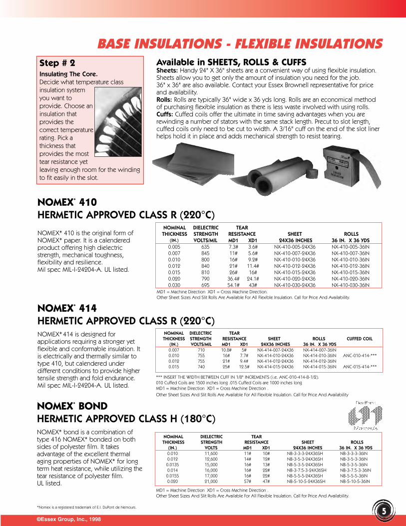
Step # 2Insulating The Core.Decide what temperature classinsulation systemyou want toprovide. Choose aninsulation thatprovides thecorrect temperaturerating. Pick athickness thatprovides the mosttear resistance yetleaving enough room for the windingto fit easily in the slot.
Available in SHEETS, ROLLS & CUFFSSheets: Handy 24" X 36" sheets are a convenient way of using flexible insulation.Sheets allow you to get only the amount of insulation you need for the job.36" x 36" are also available. Contact your Essex Brownell representative for priceand availability.Rolls: Rolls are typically 36" wide x 36 yds long. Rolls are an economical methodof purchasing flexible insulation as there is less waste involved with using rolls.Cuffs: Cuffed coils offer the ultimate in time saving advantages when you arerewinding a number of stators with the same stack length. Precut to slot length,cuffed coils only need to be cut to width. A 3/16" cuff on the end of the slot linerhelps hold it in place and adds mechanical strength to resist tearing.
NOMEX* 410 HERMETIC APPROVED CLASS R (220°C)
NOMEX* 410 is the original form ofNOMEX* paper. It is a calenderedproduct offering high dielectricstrength, mechanical toughness,flexibility and resilience.Mil spec MIL-I-24204-A. UL listed.
NOMINAL DIELECTRIC TEARTHICKNESS STRENGTH RESISTANCE SHEET ROLLS
(IN.) VOLTS/MIL MD1 XD1 24X36 INCHES 36 IN. X 36 YDS0.005 635 7.3# 3.6# NX-410-005-24X36 NX-410-005-36IN0.007 845 11# 5.6# NX-410-007-24X36 NX-410-007-36IN0.010 800 16# 9.2# NX-410-010-24X36 NX-410-010-36IN0.012 840 21# 11.4# NX-410-012-24X36 NX-410-012-36IN0.015 810 26# 16# NX-410-015-24X36 NX-410-015-36IN0.020 790 36.4# 24.1# NX-410-020-24X36 NX-410-020-36IN0.030 695 54.1# 43# NX-410-030-24X36 NX-410-030-36IN
NOMEX* 414 HERMETIC APPROVED CLASS R (220°C)NOMEX* 414 is designed forapplications requiring a stronger yetflexible and conformable insulation. Itis electrically and thermally similar totype 410, but calendered underdifferent conditions to provide highertensile strength and fold endurance.Mil spec MIL-I-24204-A. UL listed.
NOMINAL DIELECTRIC TEARTHICKNESS STRENGTH RESISTANCE SHEET ROLLS CUFFED COIL
(IN.) VOLTS/MIL MD1 XD1 24X36 INCHES 36 IN. X 36 YDS0.007 710 10.8# 5# NX-414-007-24X36 NX-414-007-36IN0.010 755 16# 7.7# NX-414-010-24X36 NX-414-010-36IN ANC-010-414-***0.012 755 21# 9.4# NX-414-012-24X36 NX-414-012-36IN0.015 740 25# 12.5# NX-414-015-24X36 NX-414-015-36IN ANC-015-414-***
NOMEX* BOND HERMETIC APPROVED CLASS H (180°C)NOMEX* bond is a combination oftype 416 NOMEX* bonded on bothsides of polyester film. It takesadvantage of the excellent thermalaging properties of NOMEX* for longterm heat resistance, while utilizing thetear resistance of polyester film. UL listed.
NOMINAL DIELECTRIC TEARTHICKNESS STRENGTH RESISTANCE SHEET ROLLS
(IN.) VOLTS MD1 XD1 24X36 INCHES 36 IN. X 36 YDS0.010 11,600 11# 10# NB-3-3-3-24X36SH NB-3-3-3-36IN0.012 12,600 14# 12# NB-3-5-3-24X36SH NB-3-5-3-36IN
0.0135 15,000 16# 13# NB-5-3-5-24X36SH NB-5-3-5-36IN0.014 16,000 16# 22# NB-3-7.5-3-24X36SH NB-3-7.5-3-36IN0.0155 17,000 16# 22# NB-5-5-5-24X36SH NB-5-5-5-36IN0.020 21,000 57# 47# NB-5-10-5-24X36SH NB-5-10-5-36IN
BASE INSULATIONS - FLEXIBLE INSULATIONS
MD1 = Machine Direction XD1 = Cross Machine Direction.Other Sheet Sizes And Slit Rolls Are Available For All Flexible Insulation. Call for Price And Availability.
*** INSERT THE WIDTH BETWEEN CUFF IN 1/8" INCREMENTS (i.e. ANC-010-414-8-1/2). 010 Cuffed Coils are 1500 inches long .015 Cuffed Coils are 1000 inches longMD1 = Machine Direction XD1 = Cross Machine Direction .Other Sheet Sizes And Slit Rolls Are Available For All Flexible Insulation. Call for Price And Availability
MD1 = Machine Direction XD1 = Cross Machine Direction . Other Sheet Sizes And Slit Rolls Are Available For All Flexible Insulation. Call for Price And Availability.
5*Nomex is a registered trademark of E.I. DuPont de Nemours.
©Essex Group, Inc., 1998
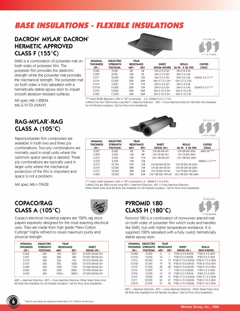
COPACO/RAGCLASS A (105°C)Copaco electrical insulating papers are 100% rag stockpapers expressly designed for the most exacting electricaluses. They are made from high grade "New CottonCuttings" highly refined to insure maximum purity andphysical strength.
BASE INSULATIONS - FLEXIBLE INSULATIONS
DACRON* MYLAR* DACRON*
HERMETIC APPROVEDCLASS F (155°C)DMD is a combination of polyester mat onboth sides of polyester film. Thepolyester film provides the dielectricstrength while the polyester mat providesthe mechanical strength. The polyester maton both sides is fully saturated with ahermetically stable epoxy resin to impartsmooth abrasion-resistant surfaces.
Mil spec MIL-I-22834. MIL-E-917D (NAVY)
NOMINAL DIELECTRIC TEARTHICKNESS STRENGTH RESISTANCE SHEET ROLLS CUFFED
(IN.) VOLTS/MIL MD1 XD1 24X36 INCHES 36 IN. X 36 YDS COILS0.006 9,000 8# 5# DM-2-2-2-SH DM-2-2-2-RL0.009 8,900 12# 9# DM-3-3-3-SH DM-3-3-3-RL0.011 12,000 18# 13# DM-3-5-3-SH DM-3-5-3-RL ADMD-3-5-3-***0.014 15,000 25# 20# DM-3-7.5-3-SH DM-3-7.5-3-RL0.014 9,300 17# 11# DM-5-3-5-SH DM-5-3-5-RL0.0154 14,000 22# 15# DM-5-5-5-SH DM-5-5-5-RL ADMD-5-5-5-***0.016 19,800 25# 24# DM-3-10-3-SH DM-3-10-3-RL0.020 17,600 34# 26# DM-5-10-5-SH DM-5-10-5-RL
RAG-MYLAR*-RAGCLASS A (105°C)Paper/polyester film composites areavailable in both two and three plycombinations. Two ply combinations arenormally used in small units where theoptimum space savings is desired. Threeply combinations are typically used inlarger units where the mechanicalprotection of the film is important andspace is not a problem.
Mil spec MIL-I-19632.
NOMINAL DIELECTRIC TEARTHICKNESS STRENGTH RESISTANCE SHEET ROLLS CUFFED
(IN.) VOLTS/MIL MD1 XD1 24X36 (IN.) 36 IN. X 36 YDS COILS0.007 8,000 9# 7# CM-5R-2M-SH CM-5R-2M-36IN ARM-52-***0.009 9,000 10# 8# CM-7R-2M-SH CM-7R-2M-36IN0.012 9,000 14# 11# CM-10R-2M-SH CM-10R-2M-36IN0.012 9,500 15# 13# ARMR-5-1-5-***0.013 12,740 21# 16# CM-5R-2M-5R-SH CM-5R-2M-5R-36IN0.014 10,000 28# 14# CM-5R-3M-5R-SH CM-5R-3M-5R-36IN0.017 12,000 30# 23# CM-7R-2M-7R-SH CM-7R-2M-7R-36IN0.023 12,200 30# 23# CM-10R-2M-10R-SH CM-10R-2M-10R-36IN
NOMINAL DIELECTRIC TEARTHICKNESS STRENGTH RESISTANCE SHEET
(IN.) VOLTS/MIL MD1 XD1 24X36 (IN.)0.005 300 180 220 CP-005-24X36-SH0.007 300 280 380 CP-007-24X36-SH0.010 300 550 700 CP-010-24X36-SH0.015 300 850 1200 CP-015-24X36-SH0.020 300 1400 1700 CP-020-24X36-SH0.025 300 1600 2200 CP-025-24X36-SH0.030 300 1600 2200 CP-030-24X36-SH
PYROMID 180CLASS H (180°C)Pyromid 180 is a combination of nonwoven aramid maton both sides of polyester film which looks and handleslike DMD, but with higher temperature resistance. It issupplied 100% saturated with a fully cured, hermeticallystable epoxy resin.
NOMINAL DIELECTRIC TEARTHICKNESS STRENGTH RESISTANCE SHEET ROLLS
(IN.) VOLTS/MIL MD1 XD1 24X36 (IN.) 36IN.X36YDS.0.0085 10,000 6 4 P180-2-3-2-24X36 P180-2-3-2-36IN0.0105 14,000 10 7 P180-2-5-2-24X26 P180-2-5-2-36IN0.013 20,000 14 13 P180-2-7.5-2-24X36 P180-2-7.5-2-36IN
0.0152 21,000 19 16 P180-2-10-2-24X36 P180-2-10-2-36IN0.019 27,000 28 28 P180-2-14-2-24X36 P180-2-14-2-36IN0.010 10,000 10 7 P180-3-3-3-24X36 P180-3-3-3-36IN0.012 13,000 13 10 P180-3-5-3-24X36 P180-3-5-3-36IN0.015 18,000 20 15 P180-3-7.5-3-24X36 P180-3-7.5-3-36IN0.017 23,000 24 21 P180-3-10-3-24X36 P180-3-10-3-36IN
0.0215 27,000 37 32 P180-3-14-3-24X36 P180-3-14-3-36IN
*** Insert Width Between Cuffs In 1/8" Increments (I.E. ADMD-5-5-5-7-1/4) Cuffed Coils Are 1500 Inches Long MD1 = Machine Direction XD1 = Cross Machine Direction Slit Rolls Are AvailableFor All Flexible Insulation. Call For Price And Availability.
*** Insert width between cuffs in 1/8" increments (i.e. ARMR-5-1-5-6-3/4) Cuffed Coils are 3000 inches long MD1 = Machine Direction XD1 = Cross Machine Direction . Other Sheet Sizes And Slit Rolls Are Available For All Flexible Insulation. Call for Price And Availability.
6
MD1 = Machine Direction XD1 = Cross Machine Direction Other Sheet Sizes AndSlit Rolls Are Available For All Flexible Insulation. Call for Price And Availability.
MD1 = Machine Direction XD1 = Cross Machine Direction Other Sheet Sizes AndSlit Rolls Are Available For All Flexible Insulation. Call for Price And Availability.
+ +
*Dacron and Mylar are registered trademarks of E.I. DuPont de Nemours.
©Essex Group, Inc., 1998
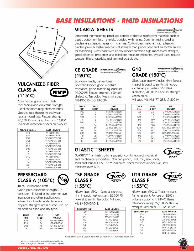
MICARTA* SHEETS Laminated thermosetting products consist of fibrous reinforcing materials such aspaper, cotton or glass materials, bonded with resins. Common resins used asbinders are phenolic, glass or melamine. Cotton base materials with phenolicbinders provide higher mechanical strength than paper base and are better suitedfor machining. Glass base with epoxy binder combine high mechanical strength,good electrical properties and excellent moisture resistance. Typical uses includespacers, fillers, topsticks and terminal boards etc.
CE GRADE(120°C)Economy grade, canvas base,phenolic binder, good moistureresistance, good machining qualities.19,000 PSI flexural strength, 600 voltdielectric. Tan color. Meets mil spec MIL-P15035-FBG, LP-509-II.
THICK LBS./ PART(IN.) SHEET NUMBER1/32 2 CE-032-36X36SH1/16 4 CE-062-36X36SH3/32 6 CE-093-36X36SH1/8 8 CE-125-36X36SH3/16 12 CE-187-36X36SH1/4 16 CE-250-36X36SH5/16 20 CE-3125-36X36SH3/8 24 CE-375-36X36SH7/16 28 CE-4375-36X36SH1/2 32 CE-500-36X36SH5/8 40.5 CE-625-36X36SH3/4 48.6 CE-750-36X36SH
G10GRADE (150°C)Glass base epoxy binder. High flexural,impact & bond strength with goodelectrical properties. 550 VPMdielectric, 70,000 PSI flexural strength.Green color. Mil spec MIL-P18177-GEE, LP-509-IV.
THICK LBS./ PART(IN.) SHEET NUMBER1/32 3.8 G10-032-36X48SH1/16 7.4 G10-062-36X48SH3/32 11 G10-093-36X48SH1/8 14.9 G10-125-36X48SH3/16 22.4 G10-187-36X48SH1/4 29.8 G10-250-36X48SH5/16 37.3 G10-3125-36X48SH3/8 44.7 G10-375-36X48SH7/16 52.2 G10-4375-36X48SH1/2 59.6 G10-500-36X48SH5/8 74.5 G10-625-36X48SH3/4 89.4 G10-750-36X48SH
VULCANIZED FIBERCLASS A (115°C)Commercial grade fiber. Highmechanical and dielectric strength.Excellent machining characteristics.Good shock absorbing and wearresistant qualities. Flexural strength26,000 PSI machine direction, 16,000PSI cross direction. Sheets are 24"x36".
THICKNESS (IN.) PART NUMBER.010 VF-RED-010-SH1/32 VF-RED-032-SH1/32 VF-GRAY-032-SH3/64 VF-GRAY-047-SH1/16 VF-RED-062-SH1/16 VF-GRAY-062-SH3/32 VF-GRAY-093-SH1/8 VF-RED-125-SH1/8 VF-GRAY-125-SH
3/16 VF-RED-187-SH1/4 VF-RED-250-SH1/4 VF-GRAY-250-SH3/8 VF-GRAY-375-SH1/2 VF-GRAY-500-SH
GLASTIC*** SHEETSGLASTIC*** laminates offer a superior combination of electricaland mechanical properties. You can punch, drill, mill, saw, shear,sand and rout all GLASTIC*** laminates. Shear thickness under 1/4", saw thickness over 1/4".
PRESSBOARDCLASS A (105°C)100% unbleached Kraftwood pulp dielectric strength 275volts per mil. Used as transformer layerinsulation and other applicationswhere the ultimate in electrical andphysical strengths are required. For useon both oil filled and dry type.
TSF GRADECLASS F(155°C)NEMA spec GPO-1 General purpose,high impact, heat resistant. 22,300 PSIflexural strength. Tan color. Mil specMIL-LP-509/GPO-1.
UTR GRADECLASS F(155°C)NEMA spec GPO-3, Track resistant,flame resistant. For use on 2500+voltage equipment. 94V-O flameretardance rating. 22,100 PSI flexuralstrength. Red color. UL File E81928.
THICK LBS./ PART(IN.) SHEET NUMBER1/32 1.43 GP-032-28X421/16 2.76 GP-062-28X423/32 4.15 GP-093-28X421/8 5.52 GP-125-28X42
Other Sheet Sizes & Grades Available on Request. Call For More Information.
THICKNESS (IN.) PART NUMBER1/32 TSF-1/32-36X361/16 TSF-1/16-36X363/32 TSF-3/32-36X361/8 TSF-1/8-36X363/16 TSF-3/16-36X361/4 TSF-1/4-36X363/8 TSF-3/8-36X361/2 TSF-1/2-36X36
THICKNESS (IN.) PART NUMBER1/32 UTR-1/32-36X361/16 UTR-1/16-36X363/32 UTR-3/32-36X361/8 UTR-1/8-36X363/16 UTR-3/16-36X361/4 UTR-1/4-36X363/8 UTR-3/8-36X361/2 UTR-1/2-36X36
BASE INSULATIONS - RIGID INSULATIONS
7** Micarta is a registered trademark of International Paper.*** Glastic is a registered trademark of the Glastic Corporation.
Other Grades, Sizes and Lengths Available on Request. Call For More Information.
©Essex Group, Inc., 1998
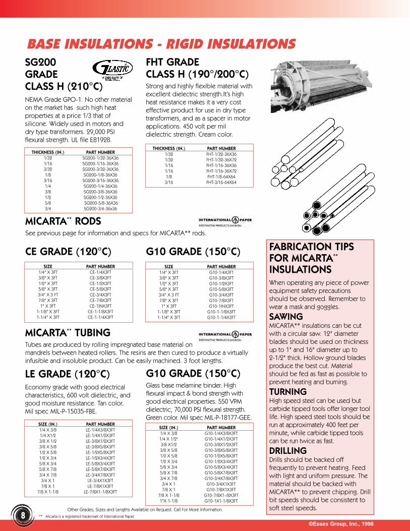
SG200GRADECLASS H (210°C)NEMA Grade GPO-1. No other materialon the market has such high heatproperties at a price 1/3 that of silicone. Widely used in motors anddry type transformers. 29,000 PSIflexural strength. UL file E81928.
FHT GRADE CLASS H (190°/200°C)Strong and highly flexible material withexcellent dielectric strength.It’s highheat resistance makes it a very costeffective product for use in dry typetransformers, and as a spacer in motorapplications. 450 volt per mildielectric strength. Cream color.
CE GRADE (120°C)
LE GRADE (120°C)Economy grade with good electricalcharacteristics, 600 volt dielectric, andgood moisture resistance. Tan color.Mil spec MIL-P-15035-FBE.
FABRICATION TIPSFOR MICARTA**
INSULATIONSWhen operating any piece of powerequipment safety precautionsshould be observed. Remember towear a mask and goggles.
SAWINGMICARTA** insulations can be cutwith a circular saw. 12" diameterblades should be used on thicknessup to 1" and 16" diameter up to2-1/2" thick. Hollow ground bladesproduce the best cut. Materialshould be fed as fast as possible toprevent heating and burning.
TURNINGHigh speed steel can be used but carbide tipped tools offer longer toollife. High speed steel tools should berun at approximately 400 feet perminute, while carbide tipped toolscan be run twice as fast.
DRILLINGDrills should be backed offfrequently to prevent heating. Feedwith light and uniform pressure. Thematerial should be backed withMICARTA** to prevent chipping. Drillbit speeds should be consistent tosoft steel speeds.
THICKNESS (IN.) PART NUMBER1/32 SG200-1/32-36X361/16 SG200-1/16-36X363/32 SG200-3/32-36X361/8 SG200-1/8-36X363/16 SG200-3/16-36X361/4 SG200-1/4-36X363/8 SG200-3/8-36X361/2 SG200-1/2-36X365/8 SG200-5/8-36X363/4 SG200-3/4-36x36
THICKNESS (IN.) PART NUMBER1/32 FHT-1/32-36X361/32 FHT-1/32-36X721/16 FHT-1/16-36X361/16 FHT-1/16-36X721/8 FHT-1/8-64X643/16 FHT-3/16-64X64
G10 GRADE (150°C)SIZE PART NUMBER
1/4" X 3FT CE-1/4X3FT3/8" X 3FT CE-3/8X3FT1/2" X 3FT CE-1/2X3FT5/8" X 3FT CE-5/8X3FT3/4" X 3 FT CE-3/4X3FT7/8" X 3FT CE-7/8X3FT1" X 3FT CE-1INX3FT
1-1/8" X 3FT CE-1-1/8X3FT1-1/4" X 3FT CE-1-1/4X3FT
SIZE PART NUMBER1/4" X 3FT G10-1/4X3FT3/8" X 3FT G10-3/8X3FT1/2" X 3FT G10-1/2X3FT5/8" X 3FT G10-5/8X3FT3/4" X 3 FT G10-3/4X3FT7/8" X 3FT G10-7/8X3FT1" X 3FT G10-1INX3FT
1-1/8" X 3FT G10-1-1/8X3FT1-1/4" X 3FT G10-1-1/4X3FT
MICARTA** TUBINGTubes are produced by rolling impregnated base material onmandrels between heated rollers. The resins are then cured to produce a virtuallyinfusible and insoluble product. Can be easily machined. 3 foot lengths.
SIZE (IN.) PART NUMBER1/4 X 3/8 LE-1/4X3/8X3FT1/4 X1/2 LE-1/4X1/2X3FT3/8 X 1/2 LE-3/8X1/2X3FT3/8 X 5/8 LE-3/8X5/8X3FT1/2 X 5/8 LE-1/2X5/8X3FT1/2 X 3/4 LE-1/2X3/4X3FT5/8 X 3/4 LE-5/8X3/4X3FT5/8 X 7/8 LE-5/8X7/8X3FT3/4 X 7/8 LE-3/4X7/8X3FT3/4 X 1 LE-3/4X1X3FT7/8 X 1 LE-7/8X1X3FT
7/8 X 1-1/8 LE-7/8X1-1/8X3FT
SIZE (IN.) PART NUMBER1/4 X 3/8 G10-1/4X3/8X3FT1/4 X 1/2" G10-1/4X1/2X3FT3/8 X1/2 G10-3/8X1/2X3FT3/8 X 5/8 G10-3/8X5/8X3FT1/2 X 5/8 G10-1/2X5/8X3FT1/2 X 3/4 G10-1/2X3/4X3FT5/8 X 3/4 G10-5/8X3/4X3FT5/8 X 7/8 G10-5/8X7/8X3FT3/4 X 7/8 G10-3/4X7/8X3FT3/4 X 1 G10-3/4X1X3FT7/8 X 1 G10-7/8X1X3FT
7/8 X 1-1/8 G10-7/8X1-/8X3FT1"X 1-1/8 G10-1X1-1/8X3FT
BASE INSULATIONS - RIGID INSULATIONS
MICARTA** RODSSee previous page for information and specs for MICARTA** rods.
8
G10 GRADE (150°C)Glass base melamine binder. Highflexural impact & bond strength withgood electrical properties. 550 VPMdielectric, 70,000 PSI flexural strength.Green color. Mil spec MIL-P-18177-GEE.
** Micarta is a registered trademark of International Paper.
©Essex Group, Inc., 1998
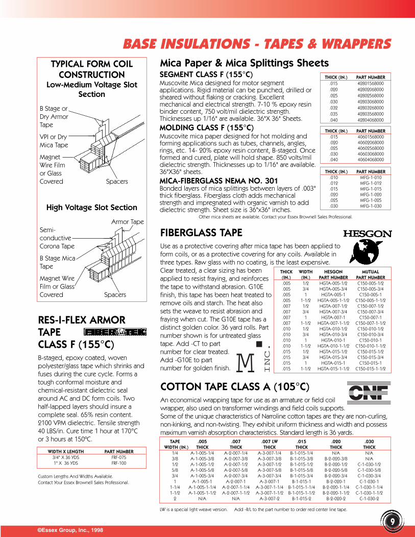
TYPICAL FORM COILCONSTRUCTION
Low-Medium Voltage SlotSection
B Stage orDry ArmorTape
VPI or DryMica Tape
MagnetWire Filmor GlassCovered Spacers
High Voltage Slot Section
Armor Tape Semi-conductiveCorona Tape
B Stage MicaTape
Magnet WireFilm or GlassCovered Spacers
Mica Paper & Mica Splittings Sheets THICK (IN.) PART NUMBER
.015 42801568000
.020 42802068000
.025 42802568000
.030 42803068000
.032 42803268000
.035 42803568000
.040 42804068000
THICK (IN.) PART NUMBER.015 40601568000.020 40602068000.025 40602568000.030 40603068000.040 40604068000
FIBERGLASS TAPEUse as a protective covering after mica tape has been applied toform coils, or as a protective covering for any coils. Available inthree types. Raw glass with no coating, is the least expensive.Clear treated, a clear sizing has beenapplied to resist fraying, and reinforcesthe tape to withstand abrasion. G10Efinish, this tape has been heat treated toremove oils and starch. The heat alsosets the weave to resist abrasion andfraying when cut. The G10E tape has adistinct golden color. 36 yard rolls. Partnumber shown is for untreated glasstape. Add -CT to partnumber for clear treated.Add -G10E to partnumber for golden finish.
THICK WIDTH HESGON MUTUAL(IN.) (IN.) PART NUMBER PART NUMBER.005 1/2 HGTA-005-1/2 C150-005-1/2.005 3/4 HGTA-005-3/4 C150-005-3/4.005 1 HGTA-005-1 C150-005-1.005 1-1/2 HGTA-005-1-1/2 C150-005-1-1/2.007 1/2 HGTA-007-1/2 C150-007-1/2.007 3/4 HGTA-007-3/4 C150-007-3/4.007 1 HGTA-007-1 C150-007-1.007 1-1/2 HGTA-007-1-1/2 C150-007-1-1/2.010 1/2 HGTA-010-1/2 C150-010-1/2.010 3/4 HGTA-010-3/4 C150-010-3/4.010 1 HGTA-010-1 C150-010-1.010 1-1/2 HGTA-010-1-1/2 C150-010-1-1/2.015 1/2 HGTA-015-1/2 C150-015-1/2.015 3/4 HGTA-015-3/4 C150-015-3/4.015 1 HGTA-015-1 C150-015-1.015 1-1/2 HGTA-015-1-1/2 C150-015-1-1/2
COTTON TAPE CLASS A (105°C)An economical wrapping tape for use as an armature or field coilwrapper, also used on transformer windings and field coils supports.Some of the unique characteristics of Narroline cotton tapes are they are non-curling,non-kinking, and non-twisting. They exhibit uniform thickness and width and possessmaximum varnish absorption characteristics. Standard length is 36 yards.
TAPE .005 .007 .007 LW .015 .020 .030WIDTH (IN.) THICK THICK THICK THICK THICK THICK
1/4 A-1-005-1/4 A-2-007-1/4 A-3-007-1/4 B-1-015-1/4 N/A N/A3/8 A-1-005-3/8 A-2-007-3/8 A-3-007-3/8 B-1-015-3/8 B-2-020-3/8 N/A1/2 A-1-005-1/2 A-2-007-1/2 A-3-007-1/2 B-1-015-1/2 B-2-020-1/2 C-1-030-1/25/8 A-1-005-5/8 A-2-007-5/8 A-3-007-5/8 B-1-015-5/8 B-2-020-5/8 C-1-030-5/83/4 A-1-005-3/4 A-2-007-3/4 A-3-007-3/4 B-1-015-3/4 B-2-020-3/4 C-1-030-3/41 A-1-005-1 A-2-007-1 A-3-007-1 B-1-015-1 B-2-020-1 C-1-030-1
1-1/4 A-1-005-1-1/4 A-2-007-1-1/4 A-3-007-1-1/4 B-1-015-1-1/4 B-2-020-1-1/4 C-1-030-1-1/41-1/2 A-1-005-1-1/2 A-2-007-1-1/2 A-3-007-1-1/2 B-1-015-1-1/2 B-2-020-1-1/2 C-1-030-1-1/2
2 N/A N/A A-3-007-2 B-1-015-2 B-2-020-2 C-1-030-2
RES-I-FLEX ARMORTAPECLASS F (155°C)B-staged, epoxy coated, wovenpolyester/glass tape which shrinks andfuses during the cure cycle. Forms atough conformal moisture andchemical-resistant dielectric sealaround AC and DC form coils. Twohalf-lapped layers should insure acomplete seal. 65% resin content.2100 VPM dielectric. Tensile strength40 LBS/in. Cure time 1 hour at 170°Cor 3 hours at 150ºC.
Custom Lengths And Widths Available.Contact Your Essex Brownell Sales Professional.
WIDTH X LENGTH PART NUMBER3/4" X 36 YDS FRF-0751" X 36 YDS FRF-100
M INC.
BASE INSULATIONS - TAPES & WRAPPERS
SEGMENT CLASS F (155°C)Muscovite Mica designed for motor segmentapplications. Rigid material can be punched, drilled orsheared without flaking or cracking. Excellentmechanical and electrical strength. 7-10 % epoxy resinbinder content, 750 volt/mil dielectric strength.Thicknesses up 1/16" are available. 36"X 36" Sheets.MOLDING CLASS F (155°C)Muscovite mica paper designed for hot molding andforming applications such as tubes, channels, angles,rings, etc. 14- 20% epoxy resin content, B-staged. Onceformed and cured, plate will hold shape. 850 volts/mildielectric strength. Thicknesses up to 1/16" are available.36"X36" sheets.MICA-FIBERGLASS NEMA NO. 301 Bonded layers of mica splittings between layers of .003"thick fiberglass. Fiberglass cloth adds mechanicalstrength and impregnated with organic varnish to adddielectric strength. Sheet size is 36"x36" inches.
Other mica sheets are available. Contact your Essex Brownell Sales Professional.
THICK (IN.) PART NUMBER.010 MFG-1-010.012 MFG-1-012.015 MFG-1-015.020 MFG-1-020.025 MFG-1-025.030 MFG-1-030
9LW is a special light weave version. Add -R/L to the part number to order red center line tape.
36 YARD ROLLSWIDTH (IN.) PART NUMBER
1/2 PEI126-1/2-36YD3/4 PEI346-3/4-36YD1 PEI1006-1-36YD
1-1/2 PEI1126-1-1/2-36YD72 YARD ROLLS
1/2 PEI122-1/2-72YD3/4 PEI342-3/4-72YD1 PEI1002-1-72YD
1-1/2 PEI1122-1-1/2-72YD
©Essex Group, Inc., 1998
BASE INSULATIONS - MICA & SEMI-CONDUCTIVE TAPES
VPI MICA TAPES & WRAPPERSCLASS F (155°C)Porous mica paper/glassfabric/polyester fleece. Bonded withminimal amount of binder for highresin absorption in VPI systems.Typical applications include groundinsulation for form wound coilsoperating at low to high voltages.Insulation for pole and interpoles ontraction motors.
OVERALL MICA %THICK. PAPER RESIN WIDTH PART(IN.) THICK. CONTENT (IN.) NUMBER.0075 .004 14-16 3/4 4371070075036*.0075 .004 14-16 1 4371070100036*.0075 .004 14-16 36 4371073600050D.0075 .003 16-18 3/4 4373200075036*.0075 .003 16-18 1 4373200100036*.0075 .003 16-18 36 4373203600050D.008 .004 16-18 3/4 4378200075036*.008 .004 16-18 1 4378200100036*.008 .004 16-18 36 4378203600050D
*Insert Core Code A= 3/8”, B= 1”, C=1-1/2”, D=3”
FULLY CURED MICA TAPES& WRAPPERSFilm face tape is a combination ofpolyester film on both sides of micapaper/glass cloth. Designed for use indip and bake applications. Suitable foruse as ground insulation on low tomedium voltages. Silicone binders aresuitable for Class H (180°C). Polyesterand epoxy modified polyester bindersare suitable for Class F (155°C).
OVERALL MICA %THICK. PAPER RESIN RESID PART(IN.) THICK. CONTENT TYPE NUMBER.005 .0018 22 Silicone 435105*.0055 .002 24 Epoxy Mod. Polyester 11903*.006 .002 22 Polyester 64213*.006 .0025 24 Epoxy Mod. Polyester 11969*.0065 .0025 22 Polyester 64217*.007 .004 21 Silicone 435107*.0075 .004 22 Polyester 64206*.008 .005 18 Polyester 64300*
* Insert width (standard widths are 3/4", 1" and 36") length,and core size A= 3/8”, B= 1”, C=1-1/2”, D=3” Ex:6420600075036C Special widths and lengths are available.
B-STAGED TAPES & WRAPPERSCLASS F (155°C)4800 series utilizes Mica paper/glass fabric impregnated with an epoxy B-stagedresin. Designed for use where coils are wrapped and cured before (hot pressapplications) or after installation with no additional varnish treatment. Suitable foruse as ground insulation on medium to high voltages. 12102 & 12104 areespecially well suited for use on end turns where flexibility is desired after cure.B-stage flexible polybutadiene tape remains flexible after cure, utilizes film face onboth sides of mica paper and glasscloth combination, for use in all typesof systems - dip & bake and VPI.Standard core size for tapes is1-1/2"-3" is standard for wrapper rolls.Tape rolls are 36 yards long, wrapperrolls are 50 yards long. Special rolllengths are available.
OVERALL MICA %THICK. PAPER RESIN WIDTH PART(IN.) THICK. CONTENT (IN.) NUMBER.007 .003 42 3/4 4800700075036*.007 .003 42 1 4800700100036*.007 .003 42 36 4800703600050D.0055 .0025 20 3/4 1210200075036*.0055 .0025 20 1 1210200100036*.007 .004 20 3/4 1210400075036*.007 .004 20 1 1210400100036*
*Insert Core Code A=3/8”, B=1”, C=1-1/2”, D=3”
CORONA PROTECTIONTAPESIt is generally anaccepted practice to add some formof corona protection to coils that willbe operating above 6.9 KV. Made of apolyester mat impregnated withconductive particles such as carbon.Resistance value is approximately400-1000 ohms per square. Speciallydesigned for use in the slot area ofform wound coils. 06ELR14AA orvariations of this tape may be used forpress cured applications. 06ELR14VPImay be used in VPI applications.
STYLE THICK (IN.) PART NUMBERFully Cured .004 06ELR14AA-*
VPI .004 06ELR14VPI-*
* Insert width (standard widths are 3/4", 1" and 36".Special widths and lengths are available.)
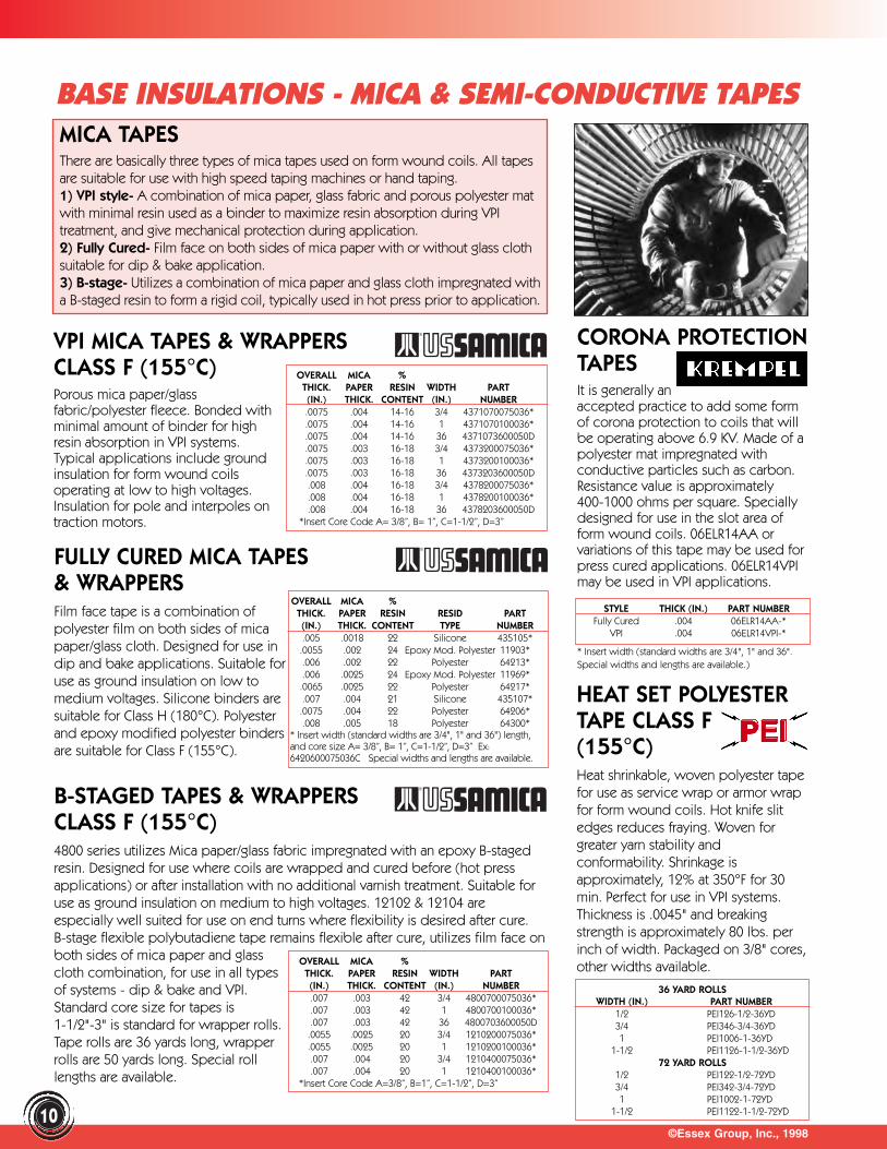
MICA TAPES There are basically three types of mica tapes used on form wound coils. All tapesare suitable for use with high speed taping machines or hand taping.1) VPI style- A combination of mica paper, glass fabric and porous polyester matwith minimal resin used as a binder to maximize resin absorption during VPItreatment, and give mechanical protection during application.2) Fully Cured- Film face on both sides of mica paper with or without glass clothsuitable for dip & bake application. 3) B-stage- Utilizes a combination of mica paper and glass cloth impregnated witha B-staged resin to form a rigid coil, typically used in hot press prior to application.
10
HEAT SET POLYESTERTAPE CLASS F(155°C)Heat shrinkable, woven polyester tapefor use as service wrap or armor wrapfor form wound coils. Hot knife slitedges reduces fraying. Woven forgreater yarn stability andconformability. Shrinkage isapproximately, 12% at 350°F for 30min. Perfect for use in VPI systems.Thickness is .0045" and breakingstrength is approximately 80 lbs. perinch of width. Packaged on 3/8" cores,other widths available.

©Essex Group, Inc., 1998
HANSCOM TIE WRAPSAvailable with a paper or a plastic cover,single or a double wire. Paper tiesprovide economical means of tying thecoils as they are being wound. Plasticties are designed for repeat use. Doublewires provide the maximum strength. Color coded for identifying the sets of coilsfor insertion. Standard feet per spool is 1500. All ties are 1/4" wide. PRE-CUT TIESAny of the Hanscom ties can be ordered pre-cut to length. If you cut your ties to3" lengths, why not order them pre-cut and save time? Ask us for a quote on yourspecifications. Dispensing Equipment Available - Ask Your Essex BrownellRepresentative.
MATERIAL TYPE PLASTIC PLASTIC PAPER PAPERCOLOR SINGLE DOUBLE SINGLE DOUBLEBLUE THT-9018-BLU THT-9088-BLU THT-5018-BLU THT-5088-BLUWHITE THT-9018-WHT THT-9088-WHT THT-5018-WHT THT-5088-WHTRED THT-9018-RED THT-9018-RED THT-5018-RED THT-5088-RED
PREMIUM QUALITYTY-WRAPSGeneral purpose nylon ties hold your coils securely during the winding process.Lightweight, high strength, flame-retardant. UL flame rating 94V-2. Mil spec MIL-M-20693A, operates at temperatures from -40°C to 85°C. 100 per package.
®
CORPORATION
STRENGTH MAX. BUNDLE DIA. (IN.) LENGTH (IN.) WIDTH (IN.) PART NUMBER18 LBS 8 3-3/8 .08 T-18S18 LBS 3/4 4 .10 T-18R18 LBS 1-1/4 5-3/4 .10 T-18I18 LBS 2 8 .10 T-18L30 LBS 1-1/4 6 .14 T-30R30 LBS 2 8 .15 T-30M30 LBS 3 11-1/4 .15 T-30I30 LBS 4 14-1/2 .15 T-30L50 LBS 1-1/4 6-1/2 .18 T-50S50 LBS 1-3/4 8 .18 T-50R50 LBS 3 11-3/4 .18 T-50I50 LBS 4 15-1/2 .18 T-50L
Other Types, Styles, Lengths And Colors Are Available By Special Order.
NYLON TWIST LOCKSA revolutionary way to holdthe coils during the windingprocess. Rounded edgesprevent abrasion. A twist ofthe fingers locks them on.Another twist releases them!Nylon twist locks have atensile strength of 20 lbs. and arereusable. Packed 100/box.
COIL CLIPS As the coils come off the windingheads, these clips attach quickly andremove easily during coil insertion.Inexpensive and reusable.
WIRE BUNDLERANGE (IN.) PART NUMBER
.20-.30 TWT-2
.30-.40 TWT-3
.40-.50 TWT-4
.55-.65 TWT-7
Step # 3When winding the coils, each coilneeds to be bundled as it istransferred off the form over to beinserted. The tie is removed anddiscarded or used again. Someshops leave the ties in place afterthe coils have been inserted. Makesure the tie will not affect theperformance of the motor.
POLYESTER SHRINKABLETIE TAPEDesigned primarily for binding andother tying applications. Narroline tietapes are available in colored tapeconstructions and colored tracerthreads for identification purposes.These tapes are flame-resistant,fungus-resistant, and fray-resistant.They offer uniform color and uniformtensile strength. Knots stay tied andresist shock, vibrations or handling.
POLYESTER TIE TAPEEconomical 100% polyester tie tape.Great for tying coilsas they come off thewinding heads. Cutoff or leave in placeduring coil insertion.1/4” wide x 1,000yards long. 22-23 lbs.breaking strength.
PART THICKNESS MIN.NUMBER (IN.) WIDTH BREAK
CNF-K615P .015 1/16 35CNF-K2515P .015 1/4 65CNF-K2530P .030 1/4 210CNF-K5030P .030 1/2 360CNF-K5050P .050 1/2 360
See page 30 for more tiecords & tie tapes. Weoffer Glass, Nomex*,
Polyester, Nylon, Linenand more!
®
CORPORATION
COIL WINDING - COIL TIES
11
PART NUMBER PTT 1/4
PART NUMBER TSC-141
*Nomex is a registered trademark of E.I. DuPont de Nemours.
©Essex Group, Inc., 1998
COIL WINDING - MAGNET WIRE
SPECIFYING MAGNET WIRE1.) Select Your Insulation Type.
Use film for general purpose applications, use dacron glass covered for abrasion resistance. See page 14 for more information.
2.) Choose Your Wire Size.Essex Brownell has round and shaped sizes available. We also have 1/2 sizes available. See page 13 for helpful hints.
3.) Pick Your Packaging.Determine what packages are available for the wire size you need, and choose the one that best serves your requirements.
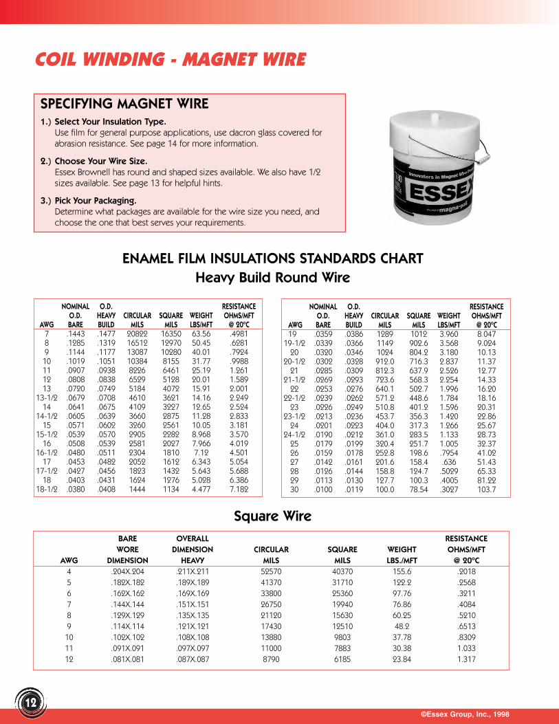
ENAMEL FILM INSULATIONS STANDARDS CHARTHeavy Build Round Wire
NOMINAL O.D. RESISTANCEO.D. HEAVY CIRCULAR SQUARE WEIGHT OHMS/MFT
AWG BARE BUILD MILS MILS LBS/MFT @ 20ºC19 .0359 .0386 1289 1012 3.960 8.047
19-1/2 .0339 .0366 1149 902.6 3.568 9.02420 .0320 .0346 1024 804.2 3.180 10.13
20-1/2 .0302 .0328 912.0 716.3 2.837 11.3721 .0285 .0309 812.3 637.9 2.526 12.77
21-1/2 .0269 .0293 723.6 568.3 2.254 14.3322 .0253 .0276 640.1 502.7 1.996 16.20
22-1/2 .0239 .0262 571.2 448.6 1.784 18.1623 .0226 .0249 510.8 401.2 1.596 20.31
23-1/2 .0213 .0236 453.7 356.3 1.420 22.8624 .0201 .0223 404.0 317.3 1.266 25.67
24-1/2 .0190 .0212 361.0 283.5 1.133 28.7325 .0179 .0199 320.4 251.7 1.005 32.3726 .0159 .0178 252.8 198.6 .7954 41.0227 .0142 .0161 201.6 158.4 .636 51.4328 .0126 .0144 158.8 124.7 .5029 65.3329 .0113 .0130 127.7 100.3 .4005 81.2230 .0100 .0119 100.0 78.54 .3027 103.7
BARE OVERALL RESISTANCEWORE DIMENSION CIRCULAR SQUARE WEIGHT OHMS/MFT
AWG DIMENSION HEAVY MILS MILS LBS./MFT @ 20ºC4 .204X.204 .211X.211 52570 40370 155.6 .20185 .182X.182 .189X.189 41370 31710 122.2 .25686 .162X.162 .169X.169 33800 25360 97.76 .32117 .144X.144 .151X.151 26750 19940 76.86 .40848 .129X.129 .135X.135 21120 15630 60.25 .52109 .114X.114 .121X.121 17430 12510 48.2 .651310 .102X.102 .108X.108 13880 9803 37.78 .830911 .091X.091 .097X.097 11000 7883 30.38 1.03312 .081X.081 .087X.087 8790 6185 23.84 1.317
Square Wire
NOMINAL O.D. RESISTANCEO.D. HEAVY CIRCULAR SQUARE WEIGHT OHMS/MFT
AWG BARE BUILD MILS MILS LBS/MFT @ 20ºC7 .1443 .1477 20822 16350 63.56 .49818 .1285 .1319 16512 12970 50.45 .62819 .1144 .1177 13087 10280 40.01 .7924
10 .1019 .1051 10384 8155 31.77 .998811 .0907 .0938 8226 6461 25.19 1.26112 .0808 .0838 6529 5128 20.01 1.58913 .0720 .0749 5184 4072 15.91 2.001
13-1/2 .0679 .0708 4610 3621 14.16 2.24914 .0641 .0675 4109 3227 12.65 2.524
14-1/2 .0605 .0639 3660 2875 11.28 2.83315 .0571 .0602 3260 2561 10.05 3.181
15-1/2 .0539 .0570 2905 2282 8.968 3.57016 .0508 .0539 2581 2027 7.966 4.019
16-1/2 .0480 .0511 2304 1810 7.12 4.50117 .0453 .0482 2052 1612 6.343 5.054
17-1/2 .0427 .0456 1823 1432 5.643 5.68818 .0403 .0431 1624 1276 5.028 6.386
18-1/2 .0380 .0408 1444 1134 4.477 7.182
12

©Essex Group, Inc., 1998
COIL WINDING - MAGNET WIRE
13
Question?When is the wrong size the right size? (Getting the most from your existing wire inventory.)
1) YOU CAN SWAP SPEC/STANDARDSThere are two standards in the industry when it comes to shaped wire, Brown/Sharpe and the decimalsystem. The Brown/Sharpe standard uses sizes like .057, .064, .072, .081, .091, .102, etc. The decimal system uses sizes like .055, .060, .065, .070, .075, .080, .085, .090, etc. The design of most windings has enough safety built into the design that a small change in the size will not effect the performance of the motor dramatically. So changing from a decimal size of .055 to a B/S size of .057 should be feasible. When making a change of this nature you must check to make sure that it will not effect the performance of the motor. For example, a coil with just a few turns will not be effected as much as a coil with a large number of turns. Considerations of physical size must also be taken into account to make sure that there is enough space available for the change.
2) USE CONDUCTORS IN PARALLEL, WITHOUT REDUCING PERFORMANCE Another option available is to use two or more conductors in parallel. For example, if you have a winding that is wound with .114 X .289 you might be able to use 2 - .057 X .289 or 4 - .057 X .144. Remember that as you use more conductors in parallel, you will be adding two insulation layers and consideration must be given if the space will allow such a change.
= =
STANDARD SHAPED WIRE SIZES.051 X .091 .057 X .162 .072 X .102 .081 X .325 .102 X .204 .128 X .182 .162 X .289.051 X .102 .057 X .182 .072 X .114 .081 X .365 .102 X .229 .128 X .204 .162 X .325.051 X .114 .057 X .204 .072 X .128 .081 X .408 .102 X .258 .128 X .229 .162 X .365.051 X .128 .057 X .229 .072 X .144 .102 X .289 .128 X .258 .162 X .408.051 X .144 .057 X .258 .072 X .162 .091 X .102 .102 X .325 .128 X .289 .162 X .458.051 X .162 .057 X .289 .072 X .182 .091 X .114 .102 X .365 .128 X .325.051 X .182 .057 X .325 .072 X .204 .091 X .128 .102 X .408 .128 X .365 .182 X .229.051 X .204 .057 X .365 .072 X .229 .091 X .144 .102 X .458 .128 X .408 .182 X .258.051 X .229 .057 X .408 .072 X .258 .091 X .162 .128 X .458 .182 X .289.051 X .258 .072 X .289 .091 X .182 .114 X .128 .182 X .325.051 X .289 .064 X .091 .072 X .325 .091 X .204 .114 X .144 .144 X .162 .182 X .365.051 X .325 .064 X .102 .072 X .365 .091 X .229 .114 X .162 .144 X .182 .182 X .408.051 X .365 .064 X .114 .072 X .408 .091 X .258 .114 X .182 .144 X .204.051 X .408 .064 X .128 .091 X .289 .114 X .204 .144 X .229 .204 X .258
.064 X .144 .081 X .102 .091 X .325 .114 X .229 .144 X .258 .204 X .289
.064 X .162 .081 X .114 .091 X .365 .114 X .258 .144 X .289 .204 X .325
.064 X .182 .081 X .128 .091 X .408 .114 X .289 .144 X .325 .204 X .365
.064 X .204 .081 X .144 .091 X .458 .114 X .325 .144 X .365
.064 X .229 .081 X .162 .114 X .365 .144 X .408 .229 X .289.057 X .091 .064 X .258 .081 X .182 .102 X .114 .114 X .410 .144 X .458 .229 X .325.057 X .102 .064 X .289 .081 X .204 .102 X .128 .114 X .460.057 X .114 .064 X .325 .081 X .229 .102 X .144 .162 X .204.057 X .128 .064 X .365 .081 X .258 .102 X .162 .128 X .144 .162 X .229.057 X .144 .064 X .408 .081 X .289 .102 X .182 .128 X .162 .162 X .258
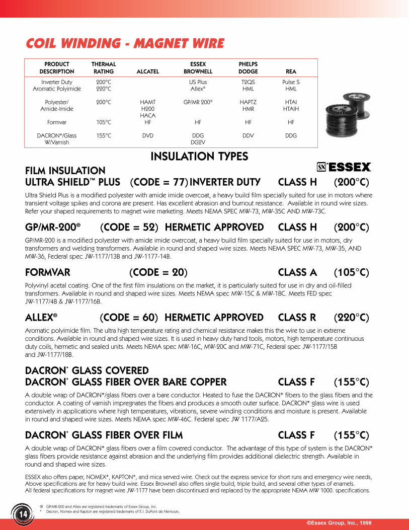
FILM INSULATIONULTRA SHIELD™ PLUS (CODE = 77) INVERTER DUTY CLASS H (200°C)Ultra Shield Plus is a modified polyester with amide imide overcoat, a heavy build film specially suited for use in motors wheretransient voltage spikes and corona are present. Has excellent abrasion and burnout resistance. Available in round wire sizes.Refer your shaped requirements to magnet wire marketing. Meets NEMA SPEC MW-73, MW-35C AND MW-73C.
GP/MR-200® (CODE = 52) HERMETIC APPROVED CLASS H (200°C)GP/MR-200 is a modified polyester with amide imide overcoat, a heavy build film specially suited for use in motors, drytransformers and welding transformers. Available in round and shaped wire sizes. Meets NEMA SPEC MW-73, MW-35, ANDMW-36, Federal spec JW-1177/13B and JW-1177-14B.
FORMVAR (CODE = 20) CLASS A (105°C)Polyvinyl acetal coating. One of the first film insulations on the market, it is particularly suited for use in dry and oil-filledtransformers. Available in round and shaped wire sizes. Meets NEMA spec MW-15C & MW-18C. Meets FED spec JW-1177/4B & JW-1177/16B.
ALLEX® (CODE = 60) HERMETIC APPROVED CLASS R (220°C)Aromatic polyimide film. The ultra high temperature rating and chemical resistance makes this the wire to use in extremeconditions. Available in round and shaped wire sizes. It is used in heavy duty hand tools, motors, high temperature continuousduty coils, hermetic and sealed units. Meets NEMA spec MW-16C, MW-20C and MW-71C, Federal spec JW-1177/15Band JW-1177/18B.
DACRON* GLASS COVEREDDACRON* GLASS FIBER OVER BARE COPPER CLASS F (155°C)A double wrap of DACRON*/glass fibers over a bare conductor. Heated to fuse the DACRON* fibers to the glass fibers and theconductor. A coating of varnish impregnates the fibers and produces a smooth outer surface. DACRON* glass wire is usedextensively in applications where high temperatures, vibrations, severe winding conditions and moisture is present. Availablein round and shaped wire sizes. Meets NEMA spec MW-46C. Federal spec JW 1177/A25.
DACRON* GLASS FIBER OVER FILM CLASS F (155°C)A double wrap of DACRON* glass fibers over a film covered conductor. The advantage of this type of system is the DACRON*glass fibers provide resistance against abrasion and the underlying film provides additional dielectric strength. Available inround and shaped wire sizes.
ESSEX also offers paper, NOMEX*, KAPTON*, and mica served wire. Check out the express service for short runs and emergency wire needs,Above specifications are for heavy build wire. Essex Brownell also offers single build, triple build, and several other types of enamels.All federal specifications for magnet wire JW-1177 have been discontinued and replaced by the appropriate NEMA MW 1000. specifications.
©Essex Group, Inc., 199814
COIL WINDING - MAGNET WIREPRODUCT THERMAL ESSEX PHELPS
DESCRIPTION RATING ALCATEL BROWNELL DODGE REA
Inverter Duty 200°C US Plus T2QS Pulse SAromatic Polyimide 220°C Allex® HML HML
Polyester/ 200°C HAMT GP/MR 200® HAPTZ HTAIAmide-Imide H200 HMR HTAIH
HACAFormvar 105°C HF HF HF HF
DACRON*/Glass 155°C DVD DDG DDV DDGW/Varnish DG2V
INSULATION TYPES
® GP/MR-200 and Allex are registered trademarks of Essex Group, Inc.* Dacron, Nomex and Kapton are registered trademarks of E.I. DuPont de Nemours.
©Essex Group, Inc., 1998
COIL WINDING - MAGNET WIRE
15
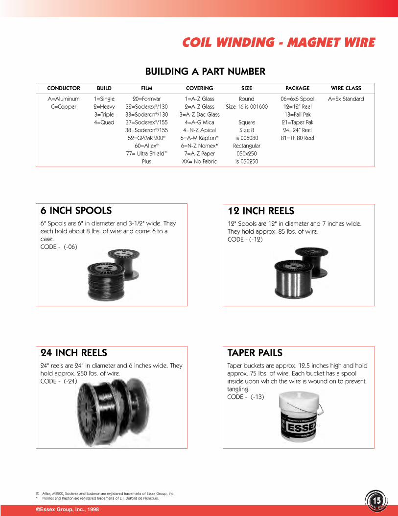
CONDUCTOR BUILD FILM COVERING SIZE PACKAGE WIRE CLASS
A=Aluminum 1=Single 20=Formvar 1=A-Z Glass Round 06=6x6 Spool A=Sx StandardC=Copper 2=Heavy 32=Soderex®/130 2=A-Z Glass Size 16 is 001600 12=12” Reel
3=Triple 33=Soderon®/130 3=A-Z Dac Glass 13=Pail Pak4=Quad 37=Soderex®/155 4=A-G Mica Square 21=Taper Pak
38=Soderon®/155 4=N-Z Apical Size 8 24=24” Reel52=GP/MR 200® 6=A-M Kapton* is 006080 81=TF 80 Reel
60=Allex® 6=N-Z Nomex* Rectangular77= Ultra Shield™ 7=A-Z Paper 050x250
Plus XX= No Fabric is 050250
6 INCH SPOOLS 6" Spools are 6" in diameter and 3-1/2" wide. Theyeach hold about 8 lbs. of wire and come 6 to acase.CODE - (-06)
12 INCH REELS 12" Spools are 12" in diameter and 7 inches wide.They hold approx. 85 lbs. of wire.CODE - (-12)
TAPER PAILS Taper buckets are approx. 12.5 inches high and holdapprox. 75 lbs. of wire. Each bucket has a spoolinside upon which the wire is wound on to preventtangling.CODE - (-13)
BUILDING A PART NUMBER
24 INCH REELS 24" reels are 24" in diameter and 6 inches wide. Theyhold approx. 250 lbs. of wire.CODE - (-24)
® Allex, MR200, Soderex and Soderon are registered trademarks of Essex Group, Inc.* Nomex and Kapton are registered trademarks of E.I. DuPont de Nemours.
Also Available In Rag Paper And Rag/Mylar*. Call Your Essex Brownell Representative.
©Essex Group, Inc., 199816
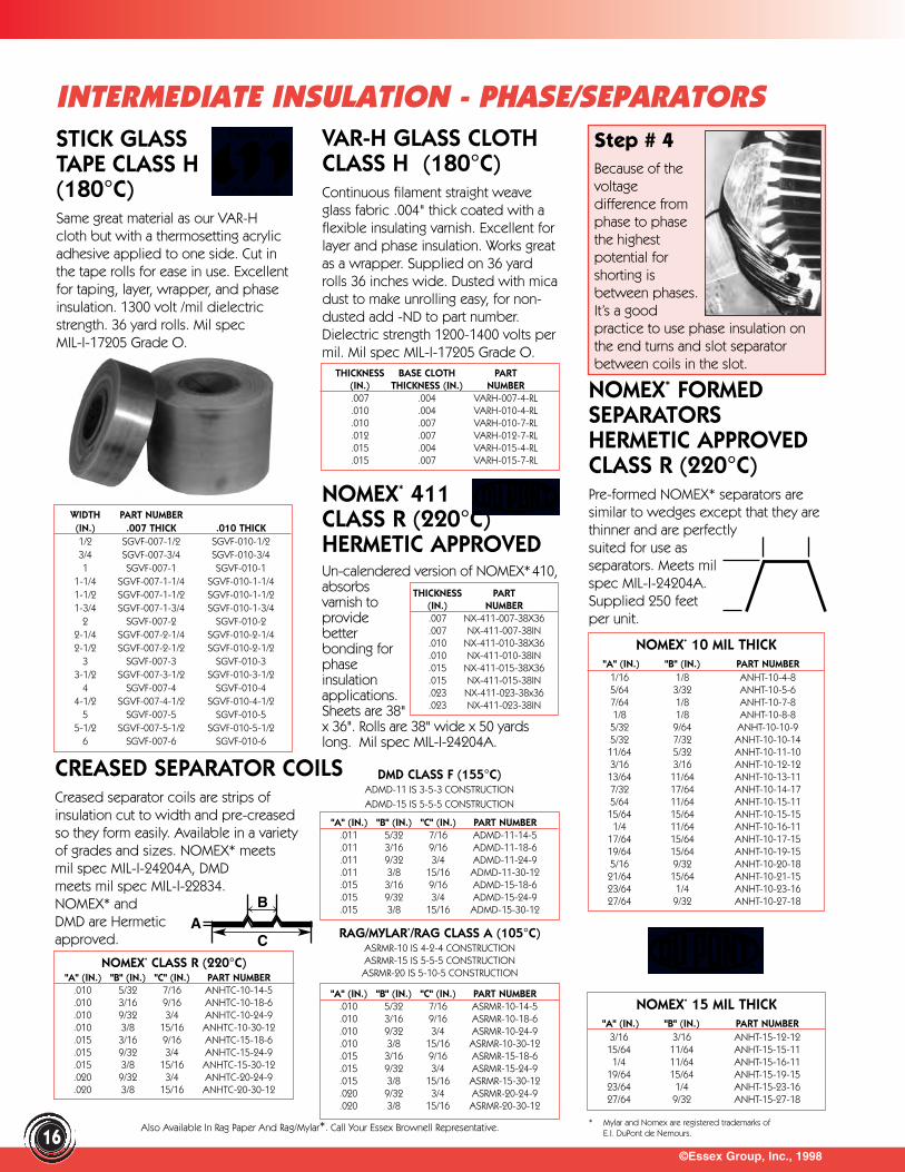
STICK GLASSTAPE CLASS H(180°C)Same great material as our VAR-Hcloth but with a thermosetting acrylicadhesive applied to one side. Cut inthe tape rolls for ease in use. Excellentfor taping, layer, wrapper, and phaseinsulation. 1300 volt /mil dielectricstrength. 36 yard rolls. Mil spec MIL-I-17205 Grade O.
VAR-H GLASS CLOTHCLASS H (180°C)Continuous filament straight weaveglass fabric .004" thick coated with aflexible insulating varnish. Excellent forlayer and phase insulation. Works greatas a wrapper. Supplied on 36 yardrolls 36 inches wide. Dusted with micadust to make unrolling easy, for non-dusted add -ND to part number.Dielectric strength 1200-1400 volts permil. Mil spec MIL-I-17205 Grade O.
NOMEX* 411 CLASS R (220°C)HERMETIC APPROVED Un-calendered version of NOMEX*410,absorbsvarnish toprovidebetterbonding forphaseinsulationapplications.Sheets are 38"x 36". Rolls are 38" wide x 50 yardslong. Mil spec MIL-I-24204A.
Step # 4Because of thevoltagedifference fromphase to phasethe highestpotential for shorting isbetween phases.It’s a good practice to use phase insulation onthe end turns and slot separatorbetween coils in the slot.
WIDTH PART NUMBER(IN.) .007 THICK .010 THICK1/2 SGVF-007-1/2 SGVF-010-1/23/4 SGVF-007-3/4 SGVF-010-3/41 SGVF-007-1 SGVF-010-1
1-1/4 SGVF-007-1-1/4 SGVF-010-1-1/41-1/2 SGVF-007-1-1/2 SGVF-010-1-1/21-3/4 SGVF-007-1-3/4 SGVF-010-1-3/4
2 SGVF-007-2 SGVF-010-22-1/4 SGVF-007-2-1/4 SGVF-010-2-1/42-1/2 SGVF-007-2-1/2 SGVF-010-2-1/2
3 SGVF-007-3 SGVF-010-33-1/2 SGVF-007-3-1/2 SGVF-010-3-1/2
4 SGVF-007-4 SGVF-010-44-1/2 SGVF-007-4-1/2 SGVF-010-4-1/2
5 SGVF-007-5 SGVF-010-55-1/2 SGVF-007-5-1/2 SGVF-010-5-1/2
6 SGVF-007-6 SGVF-010-6
THICKNESS PART (IN.) NUMBER.007 NX-411-007-38X36.007 NX-411-007-38IN.010 NX-411-010-38X36.010 NX-411-010-38IN.015 NX-411-015-38X36.015 NX-411-015-38IN.023 NX-411-023-38x36.023 NX-411-023-38IN
NOMEX* 10 MIL THICK"A" (IN.) "B" (IN.) PART NUMBER
1/16 1/8 ANHT-10-4-85/64 3/32 ANHT-10-5-67/64 1/8 ANHT-10-7-81/8 1/8 ANHT-10-8-85/32 9/64 ANHT-10-10-95/32 7/32 ANHT-10-10-1411/64 5/32 ANHT-10-11-103/16 3/16 ANHT-10-12-12
13/64 11/64 ANHT-10-13-117/32 17/64 ANHT-10-14-175/64 11/64 ANHT-10-15-11
15/64 15/64 ANHT-10-15-151/4 11/64 ANHT-10-16-11
17/64 15/64 ANHT-10-17-1519/64 15/64 ANHT-10-19-155/16 9/32 ANHT-10-20-1821/64 15/64 ANHT-10-21-1523/64 1/4 ANHT-10-23-1627/64 9/32 ANHT-10-27-18
NOMEX* 15 MIL THICK"A" (IN.) "B" (IN.) PART NUMBER
3/16 3/16 ANHT-15-12-1215/64 11/64 ANHT-15-15-111/4 11/64 ANHT-15-16-11
19/64 15/64 ANHT-15-19-1523/64 1/4 ANHT-15-23-1627/64 9/32 ANHT-15-27-18
RAG/MYLAR*/RAG CLASS A (105°C)ASRMR-10 IS 4-2-4 CONSTRUCTIONASRMR-15 IS 5-5-5 CONSTRUCTIONASRMR-20 IS 5-10-5 CONSTRUCTION
"A" (IN.) "B" (IN.) "C" (IN.) PART NUMBER.010 5/32 7/16 ASRMR-10-14-5.010 3/16 9/16 ASRMR-10-18-6.010 9/32 3/4 ASRMR-10-24-9.010 3/8 15/16 ASRMR-10-30-12.015 3/16 9/16 ASRMR-15-18-6.015 9/32 3/4 ASRMR-15-24-9.015 3/8 15/16 ASRMR-15-30-12.020 9/32 3/4 ASRMR-20-24-9.020 3/8 15/16 ASRMR-20-30-12
NOMEX* CLASS R (220°C)"A" (IN.) "B" (IN.) "C" (IN.) PART NUMBER
.010 5/32 7/16 ANHTC-10-14-5
.010 3/16 9/16 ANHTC-10-18-6
.010 9/32 3/4 ANHTC-10-24-9
.010 3/8 15/16 ANHTC-10-30-12
.015 3/16 9/16 ANHTC-15-18-6
.015 9/32 3/4 ANHTC-15-24-9
.015 3/8 15/16 ANHTC-15-30-12
.020 9/32 3/4 ANHTC-20-24-9
.020 3/8 15/16 ANHTC-20-30-12
INTERMEDIATE INSULATION - PHASE/SEPARATORS
THICKNESS BASE CLOTH PART(IN.) THICKNESS (IN.) NUMBER.007 .004 VARH-007-4-RL.010 .004 VARH-010-4-RL.010 .007 VARH-010-7-RL.012 .007 VARH-012-7-RL.015 .004 VARH-015-4-RL.015 .007 VARH-015-7-RL
"A" (IN.) "B" (IN.) "C" (IN.) PART NUMBER.011 5/32 7/16 ADMD-11-14-5.011 3/16 9/16 ADMD-11-18-6.011 9/32 3/4 ADMD-11-24-9.011 3/8 15/16 ADMD-11-30-12.015 3/16 9/16 ADMD-15-18-6.015 9/32 3/4 ADMD-15-24-9.015 3/8 15/16 ADMD-15-30-12
DMD CLASS F (155°C)ADMD-11 IS 3-5-3 CONSTRUCTIONADMD-15 IS 5-5-5 CONSTRUCTION
AC
B
NOMEX* FORMEDSEPARATORSHERMETIC APPROVEDCLASS R (220°C)Pre-formed NOMEX* separators aresimilar to wedges except that they arethinner and are perfectly suited for use as separators. Meets mil spec MIL-I-24204A.Supplied 250 feet per unit.
CREASED SEPARATOR COILSCreased separator coils are strips of insulation cut to width and pre-creased so they form easily. Available in a variety of grades and sizes. NOMEX* meets mil spec MIL-I-24204A, DMD meets mil spec MIL-I-22834. NOMEX* and DMD are Hermeticapproved.
* Mylar and Nomex are registered trademarks of E.I. DuPont de Nemours.
"A" (IN.) "B" (IN.) PART NUMBER13/64 1/8 DFP-58-25-H5/32 9/64 DFP-60-25-H7/32 9/64 DFP-65-25-H5/32 11/64 DFP-70-25-H7/32 3/16 DFP-86-25-H5/16 3/16 DFP-94-25-H1/4 7/32 DFP-99-25-H5/16 1/4 DFP-117-25-H3/8 5/16 DFP-144-25-H7/16 17/64 DFP-199-25-H
"A" (IN.) "B" (IN.) OLD PART NUMBER NEW PART NUMBER13/64 1/8 FAW-1 AFW-587/32 9/64 FAW-7 AFW-655/32 11/64 FAW-6 AFW-707/32 3/16 FAW-2 AFW-865/16 3/16 FAW-8 AFW-941/4 7/32 FAW-3 AFW-995/16 1/4 FAW-4 AFW-1173/8 5/16 FAW-9 AFW-144
©Essex Group, Inc., 1998
INTERMEDIATE INSULATION - WEDGES
17
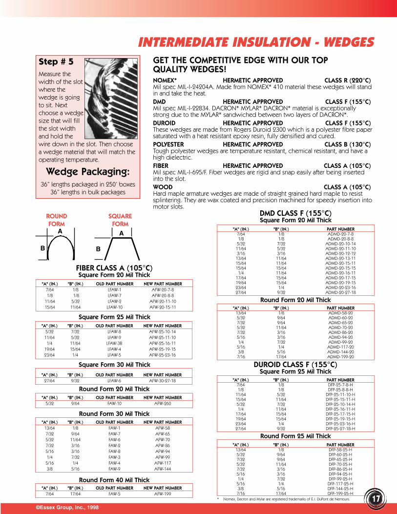
GET THE COMPETITIVE EDGE WITH OUR TOPQUALITY WEDGES!NOMEX* HERMETIC APPROVED CLASS R (220°C)Mil spec MIL-I-24204A. Made from NOMEX* 410 material these wedges will standin and take the heat.DMD HERMETIC APPROVED CLASS F (155°C)Mil spec MIL-I-22834. DACRON* MYLAR* DACRON* material is exceptionallystrong due to the MYLAR* sandwiched between two layers of DACRON*.DUROID HERMETIC APPROVED CLASS F (155°C)These wedges are made from Rogers Duroid 2300 which is a polyester fibre papersaturated with a heat resistant epoxy resin, fully densified and cured.POLYESTER HERMETIC APPROVED CLASS B (130°C)Tough polyester wedges are temperature resistant, chemical resistant, and have ahigh dielectric.FIBER HERMETIC APPROVED CLASS A (105°C)Mil spec MIL-I-695/F. Fiber wedges are rigid and snap easily after being insertedinto the slot. WOOD CLASS A (105°C) Hard maple armature wedges are made of straight grained hard maple to resist splintering. They are wax coated and precision machined for speedy insertion intomotor slots.
Step # 5Measure thewidth of the slotwhere thewedge is goingto sit. Nextchoose a wedgesize that will fillthe slot widthand hold thewire down in the slot. Then choosea wedge material that will match theoperating temperature.
Wedge Packaging:36” lengths packaged in 250’ boxes
36” lengths in bulk packages
"A" (IN.) "B" (IN.) OLD PART NUMBER NEW PART NUMBER7/64 1/8 LFAW-1 AFW-20-7-81/8 1/8 LFAW-7 AFW-20-8-8
11/64 5/32 LFAW-2 AFW-20-11-1015/64 11/64 LFAW-10 AFW-20-15-11 "A" (IN.) "B" (IN.) PART NUMBER
13/64 1/8 ADMD-58-205/32 9/64 ADMD-60-207/32 9/64 ADMD-65-205/32 11/64 ADMD-70-207/32 3/16 ADMD-86-205/16 3/16 ADMD-94-201/4 7/32 ADMD-99-205/16 1/4 ADMD-117-203/8 5/16 ADMD-144-207/16 17/64 ADMD-199-20
"A" (IN.) "B" (IN.) PART NUMBER7/64 1/8 ADMD-20-7-81/8 1/8 ADMD-20-8-8
5/32 7/32 ADMD-20-10-1411/64 5/32 ADMD-20-11-103/16 3/16 ADMD-20-12-1213/64 11/64 ADMD-20-13-1115/64 11/64 ADMD-20-15-1115/64 15/64 ADMD-20-15-151/4 11/64 ADMD-20-16-11
17/64 15/64 ADMD-20-17-1519/64 15/64 ADMD-20-19-1523/64 1/4 ADMD-20-23-1627/64 9/32 ADMD-20-27-18
DMD CLASS F (155°C)Square Form 20 Mil Thick
Square Form 25 Mil Thick
Round Form 20 Mil Thick
"A" (IN.) "B" (IN.) OLD PART NUMBER NEW PART NUMBER5/32 7/32 LFAW-8 AFW-25-10-1411/64 5/32 LFAW-9 AFW-25-11-101/4 11/64 LFAW-3B AFW-25-16-11
19/64 15/64 LFAW-4 AFW-25-19-1523/64 1/4 LFAW-5 AFW-25-23-16
Round Form 30 Mil Thick
Round Form 40 Mil Thick
Round Form 20 Mil Thick
"A" (IN.) "B" (IN.) OLD PART NUMBER NEW PART NUMBER27/64 9/32 LFAW-6 AFW-30-27-18
"A" (IN.) "B" (IN.) OLD PART NUMBER NEW PART NUMBER5/32 9/64 FAW-10 AFW-260
"A" (IN.) "B" (IN.) OLD PART NUMBER NEW PART NUMBER7/64 17/64 FAW-5 AFW-199
ROUND SQUAREFORM FORM
DUROID CLASS F (155°C)Square Form 25 Mil Thick
"A" (IN.) "B" (IN.) PART NUMBER7/64 1/8 DFP-25-7-8-H1/8 1/8 DFP-25-8-8-H
11/64 5/32 DFP-25-11-10-H15/64 11/64 DFP-25-15-11-H5/32 7/32 DFP-25-10-14-H1/4 11/64 DFP-25-16-11-H
17/64 15/64 DFP-25-17-15-H19/64 15/64 DFP-25-19-15-H23/64 1/4 DFP-25-23-16-H27/64 9/32 DFP-25-27-18-H
Round Form 25 Mil Thick
B
A
B
A
FIBER CLASS A (105°C)Square Form 20 Mil Thick
Square Form 30 Mil Thick
* Nomex, Dacron and Mylar are registered trademarks of E.I. DuPont de Nemours.
©Essex Group, Inc., 199818
INTERMEDIATE INSULATION - WEDGES
ROUND SQUAREFORM FORM
B
A
B
A
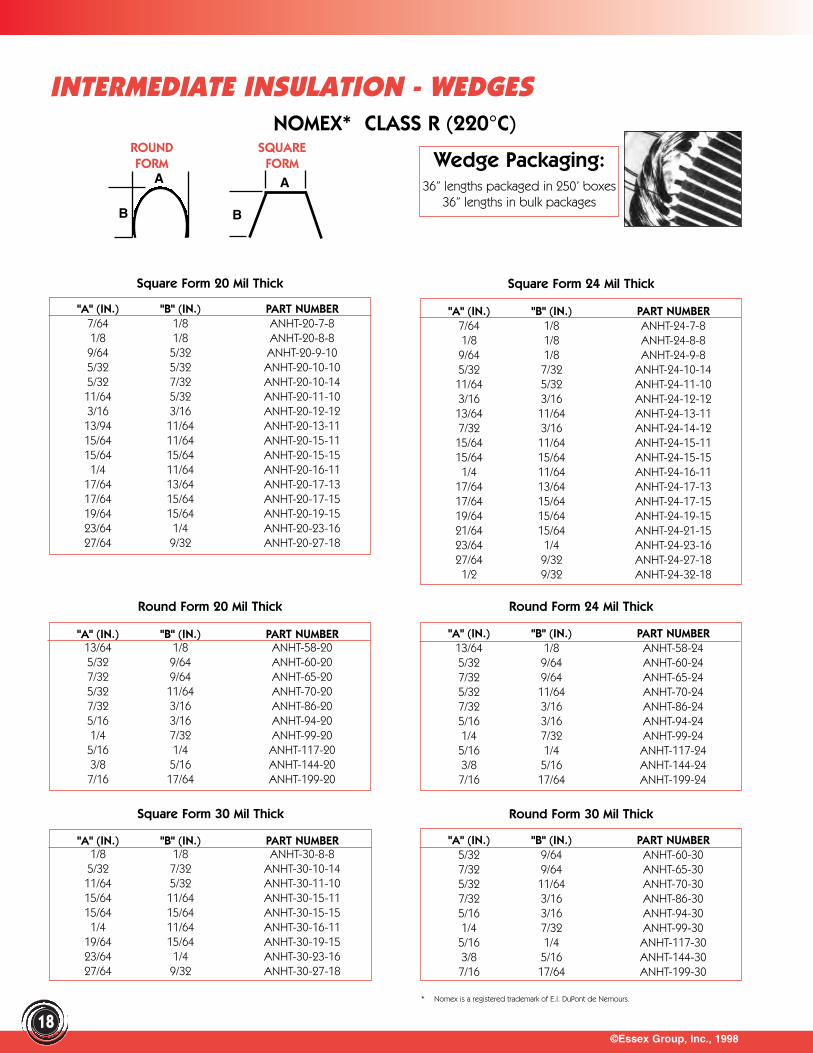
"A" (IN.) "B" (IN.) PART NUMBER1/8 1/8 ANHT-30-8-85/32 7/32 ANHT-30-10-1411/64 5/32 ANHT-30-11-1015/64 11/64 ANHT-30-15-1115/64 15/64 ANHT-30-15-151/4 11/64 ANHT-30-16-11
19/64 15/64 ANHT-30-19-1523/64 1/4 ANHT-30-23-1627/64 9/32 ANHT-30-27-18
"A" (IN.) "B" (IN.) PART NUMBER5/32 9/64 ANHT-60-307/32 9/64 ANHT-65-305/32 11/64 ANHT-70-307/32 3/16 ANHT-86-305/16 3/16 ANHT-94-301/4 7/32 ANHT-99-305/16 1/4 ANHT-117-303/8 5/16 ANHT-144-307/16 17/64 ANHT-199-30
Round Form 30 Mil Thick
"A" (IN.) "B" (IN.) PART NUMBER13/64 1/8 ANHT-58-245/32 9/64 ANHT-60-247/32 9/64 ANHT-65-245/32 11/64 ANHT-70-247/32 3/16 ANHT-86-245/16 3/16 ANHT-94-241/4 7/32 ANHT-99-245/16 1/4 ANHT-117-243/8 5/16 ANHT-144-247/16 17/64 ANHT-199-24
"A" (IN.) "B" (IN.) PART NUMBER13/64 1/8 ANHT-58-205/32 9/64 ANHT-60-207/32 9/64 ANHT-65-205/32 11/64 ANHT-70-207/32 3/16 ANHT-86-205/16 3/16 ANHT-94-201/4 7/32 ANHT-99-205/16 1/4 ANHT-117-203/8 5/16 ANHT-144-207/16 17/64 ANHT-199-20
"A" (IN.) "B" (IN.) PART NUMBER7/64 1/8 ANHT-20-7-81/8 1/8 ANHT-20-8-89/64 5/32 ANHT-20-9-105/32 5/32 ANHT-20-10-105/32 7/32 ANHT-20-10-1411/64 5/32 ANHT-20-11-103/16 3/16 ANHT-20-12-1213/94 11/64 ANHT-20-13-1115/64 11/64 ANHT-20-15-1115/64 15/64 ANHT-20-15-151/4 11/64 ANHT-20-16-11
17/64 13/64 ANHT-20-17-1317/64 15/64 ANHT-20-17-1519/64 15/64 ANHT-20-19-1523/64 1/4 ANHT-20-23-1627/64 9/32 ANHT-20-27-18
"A" (IN.) "B" (IN.) PART NUMBER7/64 1/8 ANHT-24-7-81/8 1/8 ANHT-24-8-89/64 1/8 ANHT-24-9-85/32 7/32 ANHT-24-10-1411/64 5/32 ANHT-24-11-103/16 3/16 ANHT-24-12-1213/64 11/64 ANHT-24-13-117/32 3/16 ANHT-24-14-1215/64 11/64 ANHT-24-15-1115/64 15/64 ANHT-24-15-151/4 11/64 ANHT-24-16-11
17/64 13/64 ANHT-24-17-1317/64 15/64 ANHT-24-17-1519/64 15/64 ANHT-24-19-1521/64 15/64 ANHT-24-21-1523/64 1/4 ANHT-24-23-1627/64 9/32 ANHT-24-27-181/2 9/32 ANHT-24-32-18
Square Form 24 Mil ThickSquare Form 20 Mil Thick
Wedge Packaging:36” lengths packaged in 250’ boxes
36” lengths in bulk packages
Round Form 20 Mil Thick
Square Form 30 Mil Thick
Round Form 24 Mil Thick
NOMEX* CLASS R (220°C)
* Nomex is a registered trademark of E.I. DuPont de Nemours.
B
A
©Essex Group, Inc., 199819
INTERMEDIATE INSULATION - WEDGES
SIZE W" X TH" (IN.) STYLE PART NUMBER1/8 X 5/64 1 AWW-1220
1/8 X 3/32 1 AWW-1230
5/32 X 5/64 1 AWW-121
3/16 X 5/64 1 AWW-122
5/32 X 3/32 1 AWW-131
3/16 X 3/32 1 AWW-132
7/32 X 3/32 1 AWW-133
1/4 X 3/32 1 AWW-134
9/32 X 3/32 1 AWW-135
3/16 X 1/8 1 AWW-152
7/32 X 1/8 1 AWW-153
1/4 X 1/8 1 AWW-154
9/32 X 1/8 1 AWW-155
5/16 X 1/8 1 AWW-156
3/8 X 1/8 1 AWW-158
7/16 X 1/8 1 AWW-160
5/32 X 1/8 2 AWW-251
7/32 X 1/8 2 AWW-253
1/4 X 1/8 2 AWW-254
5/16 X 1/8 2 AWW-256
3/8 X 1/8 2 AWW-258
7/32 X 3/32 3 AWW-333
1/4 X 3/16 3 AWW-374
3/16 X 1/16 4 AWW-412
5/32 X 1/8 4 AWW-451
3/16 X 1/8 4 AWW-452
7/32 X 1/8 4 AWW-453
1/4 X 1/8 4 AWW-454
9/32 X 1/8 4 AWW-455
5/16 X 1/8 4 AWW-456
11/32 X 1/8 4 AWW-457
3/8 X 1/8 4 AWW-458
3/16 X 3/16 4 AWW-472
1/4 X 3/16 4 AWW-474
9/32 X 3/16 4 AWW-475
5/16 X 3/16 4 AWW-476
11/32 X 3/16 4 AWW-477
SIZE W" X TH" (IN.) STYLE PART NUMBER9/32 X 1/8 5 AWW-555
5/32 X 5/64 6 AWW-621
3/16 X 3/32 6 AWW-632
1/4 X 3/32 6 AWW-634
3/16 X 7/64 6 AWW-642
7/32 X 7/64 6 AWW-643
5/16 X 7/64 6 AWW-646
7/32 X 1/8 6 AWW-653
5/16 X 1/8 6 AWW-656
3/8 X 1/8 6 AWW-658
3/16 X 3/32 7 AWW-732
11/64 X 7/64 7 AWW-742-A
13/64 X 1/8 7 AWW-752
13/64 X 1/8 7 AWW-753-A
15/64 X 1/8 7 AWW-754-A
5/16 X 5/16 8 AWW-816
1/4 X 3/32 8 AWW-834
5/16 X 3/32 8 AWW-836
5/16 X 1/8 8 AWW-856
3/8 X 1/8 8 AWW-858
SIZE W" X TH" (IN.) STYLE PART NUMBER1/4 X 1/4 SQUARE AWW-494
3/8 X 3/8 SQUARE AWW-3838
1/2 X 1/2 SQUARE AWW-1212
Square Form 10 Mil Thick
Square Form 14 Mil Thick
Round Form 14 Mil Thick
"A" (IN.) "B" (IN.) PART NUMBER1/8 1/8 AMFC-10-8-8
1/8 5/32 AMFC-10-8-10
5/32 3/16 AMFC-10-10-12
3/16 3/16 AMFC-10-12-12
15/64 11/64 AMFC-10-15-11
"A" (IN.) "B" (IN.) PART NUMBER7/32 3/16 AMFC-86-10
1/4 7/32 AMFC-99-10
5/16 1/4 AMFC-117-10
3/8 5/16 AMFC-144-10
"A" (IN.) "B" (IN.) PART NUMBER7/32 3/16 AMFC-86-14
1/4 7/32 AMFC-99-14
5/16 1/4 AMFC-117-14
3/8 5/16 AMFC-144-14
"A" (IN.) "B" (IN.) PART NUMBER11/64 5/32 AMFC-14-11-10
5/32 7/32 AMFC-14-10-14
19/64 15/64 AMFC-14-10-12
3/16 3/16 AMFC-14-19-15
23/64 1/4 AMFC-14-23-16
1 2 3 4 5 6 7 8
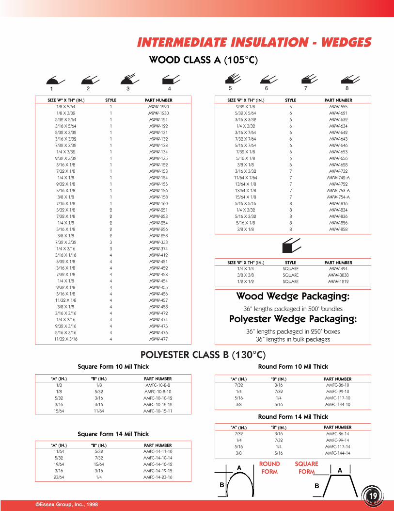
Wood Wedge Packaging:36” lengths packaged in 500’ bundles
Polyester Wedge Packaging:36” lengths packaged in 250’ boxes
36” lengths in bulk packages
ROUND SQUAREFORM FORM
B
A
WOOD CLASS A (105°C)
POLYESTER CLASS B (130°C)Round Form 10 Mil Thick
©Essex Group, Inc., 1998
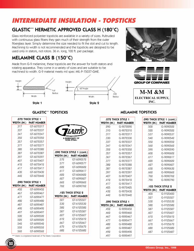
INTERMEDIATE INSULATION - TOPSTICKS
20
GLASTIC*** HERMETIC APPROVED CLASS H (180°C)Glass reinforced polyester topsticks are available in a variety of sizes. Pultrudedwith continuous glass fibers they gain much of their strength from the outer fiberglass layer. Simply determine the size needed to fit the slot and cut to length.Machining to width is not recommended and the topsticks are designed to beused only in stators, not rotors. 36 in. long, 102 ft. per package.
MELAMINE CLASS B (150°C)Made from G-9 melamine, these topsticks are the answer for both stators androtating apparatus. They come in a variety of sizes and are suitable to bemachined to width. G-9 material meets mil spec MIL-P-15037-GME.
Height
Width
FullRadius
Height
Width
60°Angle
.030Radius
Style 1 Style 2
GLASTIC*** TOPSTICKS
.072 THICK STYLE 1WIDTH (IN.) PART NUMBER
.317 GT-6072317
.337 GT-6072337
.347 GT-6072347
.352 GT-6072352
.357 GT-6072357
.377 GT-6072377
.382 GT-6072382
.387 GT-6072387
.397 GT-6072397
.407 GT-6072407
.412 GT-6072412
.417 GT-6072417
.432 GT-6072432
.442 GT-6072442
.090 THICK STYLE 1WIDTH (IN.) PART NUMBER
.452 GT-6090452
.467 GT-6090467
.477 GT-6090477
.482 GT-6090482
.487 GT-6090487
.492 GT-6090492
.497 GT-6090497
.502 GT-6090502
.522 GT-6090522
.542 GT-6090542
.552 GT-6090552
.562 GT-6090562
.090 THICK STYLE 1 (cont.)WIDTH (IN.) PART NUMBER
.572 GT-6090572
.577 GT-6090577
.602 GT-6090602
.617 GT-6090617
.622 GT-6060622
.627 GT-6090627
.662 GT-6090662
.762 GT-6090762
.125 THICK STYLE 2WIDTH (IN.) PART NUMBER
.527 GT-6125527
.532 GT-6125532
.582 GT-6125582
.587 GT-6125587
.607 GT-6125607
.612 GT-6125612
.667 GT-6125667
.672 GT-6125672
.682 GT-6125682
M-M &M ELECTRICAL SUPPLY,
INC.
MELAMINE TOPSTICKS
.072 THICK STYLE 1WIDTH (IN.) PART NUMBER
.290 G-9072290
.310 G-9072310
.317 G-9072317
.330 G-9072330
.337 G-9072337
.347 G-9072347
.352 G-9072352
.357 G-9072357
.367 G-9072367
.377 G-9072377
.382 G-9072382
.387 G-9072387
.397 G-9072397
.407 G-9072407
.412 G-9072412
.417 G-9072417
.425 G-9072425
.432 G-9072432
.442 G-9072442
.090 THICK STYLE 1WIDTH (IN.) PART NUMBER
.452 G-9090452
.462 G-9090462
.467 G-9090467
.477 G-9090477
.482 G-9090482
.487 G-9090487
.492 G-9090492
.497 G-9090497
.090 THICK STYLE 1 (cont.)WIDTH (IN.) PART NUMBER
.502 G-9090502
.522 G-9090522
.537 G-9090537
.542 G-9090542
.552 G-9090552
.562 G-9090562
.590 G-9090590
.602 G-9090602
.617 G-9090617
.622 G-9090622
.627 G-9090627
.632 G-9090632
.662 G-9090662
.762 G-9090762
.790 G-9090790
.125 THICK STYLE 2WIDTH (IN.) PART NUMBER
.400 G-9125400
.527 G-9125527
.532 G-9125532
.582 G-9125582
.587 G-9125587
.607 G-9125607
.612 G-9125612
.667 G-9125667
.672 G-9125672
.682 G-9125682
.687 G-9125687*** Glastic is a registered trademark of The Glastic Corporation.
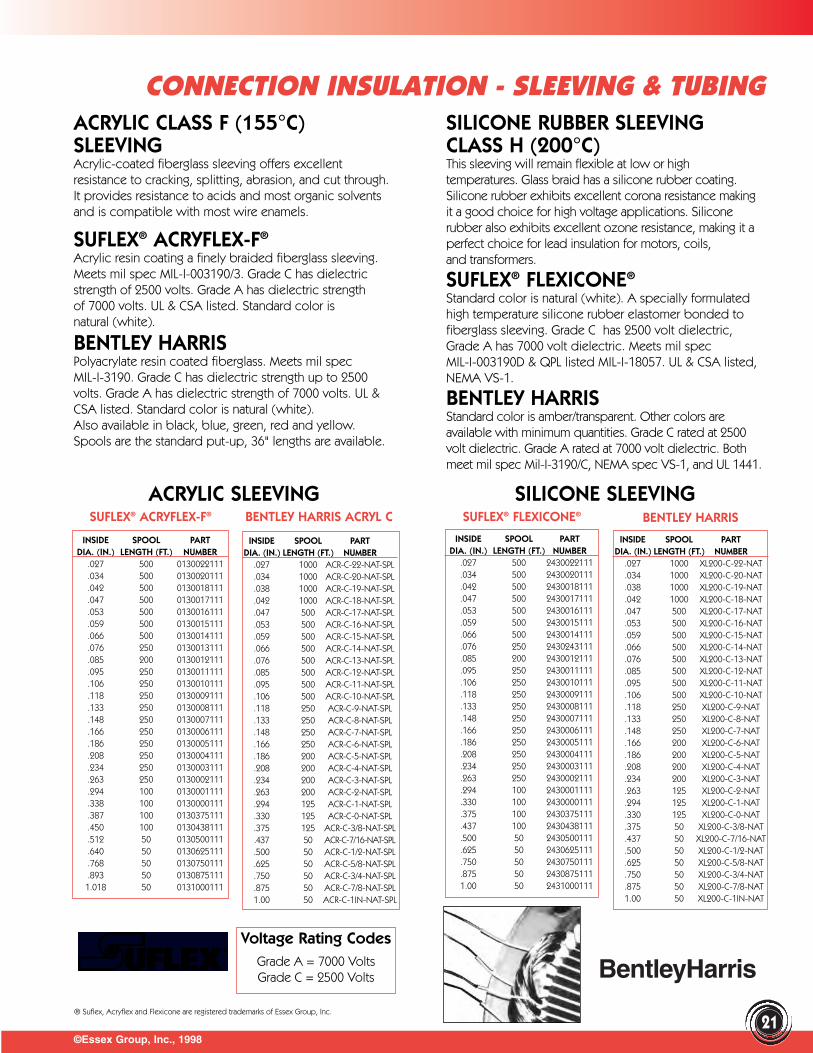
©Essex Group, Inc., 1998
CONNECTION INSULATION - SLEEVING & TUBING
21
INSIDE SPOOL PARTDIA. (IN.) LENGTH (FT.) NUMBER
.027 1000 ACR-C-22-NAT-SPL
.034 1000 ACR-C-20-NAT-SPL
.038 1000 ACR-C-19-NAT-SPL
.042 1000 ACR-C-18-NAT-SPL
.047 500 ACR-C-17-NAT-SPL
.053 500 ACR-C-16-NAT-SPL
.059 500 ACR-C-15-NAT-SPL
.066 500 ACR-C-14-NAT-SPL
.076 500 ACR-C-13-NAT-SPL
.085 500 ACR-C-12-NAT-SPL
.095 500 ACR-C-11-NAT-SPL
.106 500 ACR-C-10-NAT-SPL
.118 250 ACR-C-9-NAT-SPL
.133 250 ACR-C-8-NAT-SPL
.148 250 ACR-C-7-NAT-SPL
.166 250 ACR-C-6-NAT-SPL
.186 200 ACR-C-5-NAT-SPL
.208 200 ACR-C-4-NAT-SPL
.234 200 ACR-C-3-NAT-SPL
.263 200 ACR-C-2-NAT-SPL
.294 125 ACR-C-1-NAT-SPL
.330 125 ACR-C-0-NAT-SPL
.375 125 ACR-C-3/8-NAT-SPL
.437 50 ACR-C-7/16-NAT-SPL
.500 50 ACR-C-1/2-NAT-SPL
.625 50 ACR-C-5/8-NAT-SPL
.750 50 ACR-C-3/4-NAT-SPL
.875 50 ACR-C-7/8-NAT-SPL1.00 50 ACR-C-1IN-NAT-SPL
INSIDE SPOOL PARTDIA. (IN.) LENGTH (FT.) NUMBER
.027 500 0130022111
.034 500 0130020111
.042 500 0130018111
.047 500 0130017111
.053 500 0130016111
.059 500 0130015111
.066 500 0130014111
.076 250 0130013111
.085 200 0130012111
.095 250 0130011111
.106 250 0130010111
.118 250 0130009111
.133 250 0130008111
.148 250 0130007111
.166 250 0130006111
.186 250 0130005111
.208 250 0130004111
.234 250 0130003111
.263 250 0130002111
.294 100 0130001111
.338 100 0130000111
.387 100 0130375111
.450 100 0130438111
.512 50 0130500111
.640 50 0130625111
.768 50 0130750111
.893 50 01308751111.018 50 0131000111
ACRYLIC CLASS F (155°C)SLEEVINGAcrylic-coated fiberglass sleeving offers excellentresistance to cracking, splitting, abrasion, and cut through.It provides resistance to acids and most organic solventsand is compatible with most wire enamels.
SUFLEX® ACRYFLEX-F®
Acrylic resin coating a finely braided fiberglass sleeving.Meets mil spec MIL-I-003190/3. Grade C has dielectricstrength of 2500 volts. Grade A has dielectric strengthof 7000 volts. UL & CSA listed. Standard color isnatural (white).
BENTLEY HARRIS Polyacrylate resin coated fiberglass. Meets mil spec MIL-I-3190. Grade C has dielectric strength up to 2500volts. Grade A has dielectric strength of 7000 volts. UL &CSA listed. Standard color is natural (white).Also available in black, blue, green, red and yellow.Spools are the standard put-up, 36" lengths are available.
ACRYLIC SLEEVING SILICONE SLEEVINGSUFLEX® ACRYFLEX-F® BENTLEY HARRIS ACRYL C SUFLEX® FLEXICONE®
INSIDE SPOOL PARTDIA. (IN.) LENGTH (FT.) NUMBER
.027 500 2430022111
.034 500 2430020111
.042 500 2430018111
.047 500 2430017111
.053 500 2430016111
.059 500 2430015111
.066 500 2430014111
.076 250 2430243111
.085 200 2430012111
.095 250 2430011111
.106 250 2430010111
.118 250 2430009111
.133 250 2430008111
.148 250 2430007111
.166 250 2430006111
.186 250 2430005111
.208 250 2430004111
.234 250 2430003111
.263 250 2430002111
.294 100 2430001111
.330 100 2430000111
.375 100 2430375111
.437 100 2430438111
.500 50 2430500111
.625 50 2430625111
.750 50 2430750111
.875 50 24308751111.00 50 2431000111
INSIDE SPOOL PARTDIA. (IN.) LENGTH (FT.) NUMBER
.027 1000 XL200-C-22-NAT
.034 1000 XL200-C-20-NAT
.038 1000 XL200-C-19-NAT
.042 1000 XL200-C-18-NAT
.047 500 XL200-C-17-NAT
.053 500 XL200-C-16-NAT
.059 500 XL200-C-15-NAT
.066 500 XL200-C-14-NAT
.076 500 XL200-C-13-NAT
.085 500 XL200-C-12-NAT
.095 500 XL200-C-11-NAT
.106 500 XL200-C-10-NAT
.118 250 XL200-C-9-NAT
.133 250 XL200-C-8-NAT
.148 250 XL200-C-7-NAT
.166 200 XL200-C-6-NAT
.186 200 XL200-C-5-NAT
.208 200 XL200-C-4-NAT
.234 200 XL200-C-3-NAT
.263 125 XL200-C-2-NAT
.294 125 XL200-C-1-NAT
.330 125 XL200-C-0-NAT
.375 50 XL200-C-3/8-NAT
.437 50 XL200-C-7/16-NAT
.500 50 XL200-C-1/2-NAT
.625 50 XL200-C-5/8-NAT
.750 50 XL200-C-3/4-NAT
.875 50 XL200-C-7/8-NAT1.00 50 XL200-C-1IN-NAT
BentleyHarris
SILICONE RUBBER SLEEVINGCLASS H (200°C)This sleeving will remain flexible at low or hightemperatures. Glass braid has a silicone rubber coating.Silicone rubber exhibits excellent corona resistance makingit a good choice for high voltage applications. Siliconerubber also exhibits excellent ozone resistance, making it aperfect choice for lead insulation for motors, coils, and transformers.
SUFLEX® FLEXICONE®
Standard color is natural (white). A specially formulatedhigh temperature silicone rubber elastomer bonded tofiberglass sleeving. Grade C has 2500 volt dielectric,Grade A has 7000 volt dielectric. Meets mil specMIL-I-003190D & QPL listed MIL-I-18057. UL & CSA listed,NEMA VS-1.
BENTLEY HARRISStandard color is amber/transparent. Other colors areavailable with minimum quantities. Grade C rated at 2500volt dielectric. Grade A rated at 7000 volt dielectric. Bothmeet mil spec Mil-I-3190/C, NEMA spec VS-1, and UL 1441.
Voltage Rating CodesGrade A = 7000 VoltsGrade C = 2500 Volts
BENTLEY HARRIS
® Suflex, Acryflex and Flexicone are registered trademarks of Essex Group, Inc.
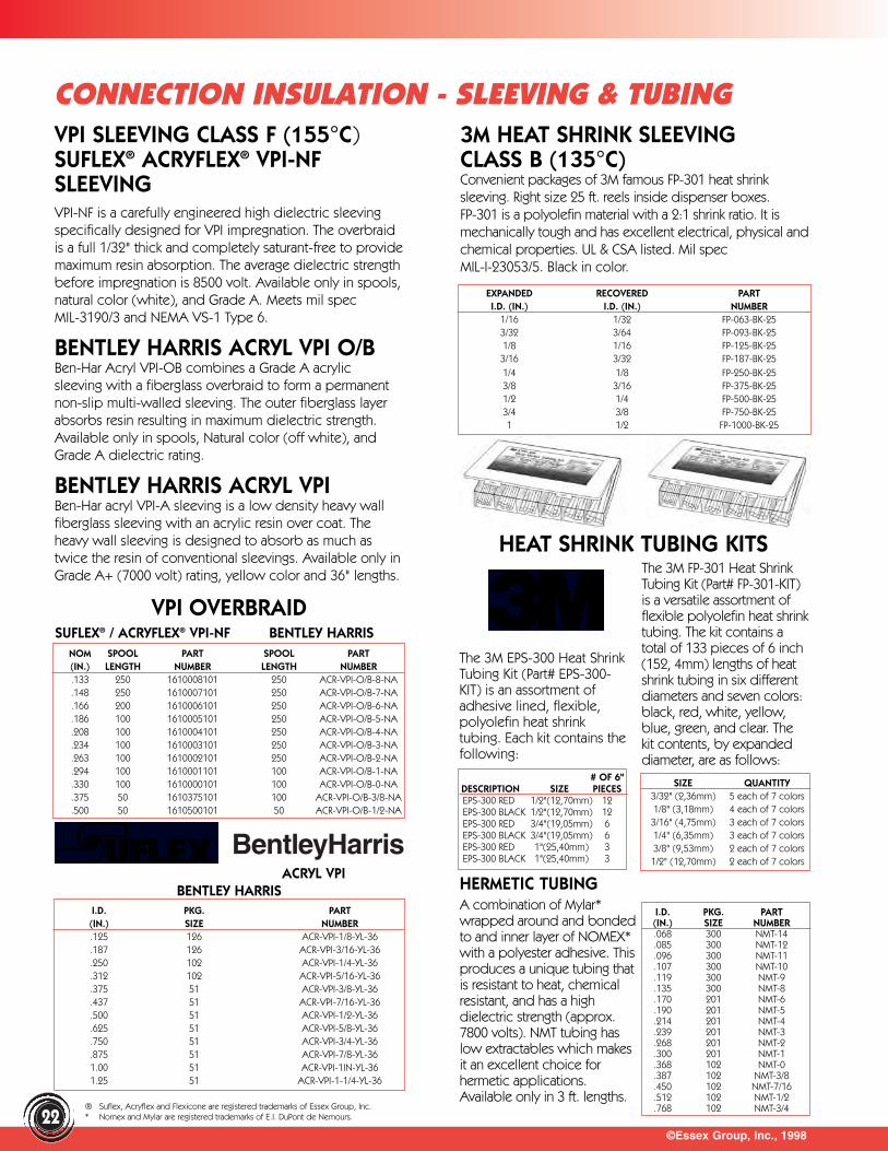
HERMETIC TUBINGA combination of Mylar*wrapped around and bondedto and inner layer of NOMEX*with a polyester adhesive. Thisproduces a unique tubing thatis resistant to heat, chemicalresistant, and has a highdielectric strength (approx.7800 volts). NMT tubing haslow extractables which makesit an excellent choice forhermetic applications.Available only in 3 ft. lengths.
©Essex Group, Inc., 199822
CONNECTION INSULATION - SLEEVING & TUBING3M HEAT SHRINK SLEEVINGCLASS B (135°C)Convenient packages of 3M famous FP-301 heat shrinksleeving. Right size 25 ft. reels inside dispenser boxes.FP-301 is a polyolefin material with a 2:1 shrink ratio. It ismechanically tough and has excellent electrical, physical andchemical properties. UL & CSA listed. Mil spec MIL-I-23053/5. Black in color.
EXPANDED RECOVERED PARTI.D. (IN.) I.D. (IN.) NUMBER
1/16 1/32 FP-063-BK-253/32 3/64 FP-093-BK-251/8 1/16 FP-125-BK-253/16 3/32 FP-187-BK-251/4 1/8 FP-250-BK-253/8 3/16 FP-375-BK-251/2 1/4 FP-500-BK-253/4 3/8 FP-750-BK-251 1/2 FP-1000-BK-25
The 3M EPS-300 Heat ShrinkTubing Kit (Part# EPS-300-KIT) is an assortment ofadhesive lined, flexible,polyolefin heat shrinktubing. Each kit contains thefollowing:
HEAT SHRINK TUBING KITSThe 3M FP-301 Heat ShrinkTubing Kit (Part# FP-301-KIT)is a versatile assortment of flexible polyolefin heat shrinktubing. The kit contains atotal of 133 pieces of 6 inch(152, 4mm) lengths of heatshrink tubing in six differentdiameters and seven colors:black, red, white, yellow,blue, green, and clear. Thekit contents, by expandeddiameter, are as follows:
# OF 6"DESCRIPTION SIZE PIECESEPS-300 RED 1/2"(12,70mm) 12EPS-300 BLACK 1/2"(12,70mm) 12EPS-300 RED 3/4"(19,05mm) 6EPS-300 BLACK 3/4"(19,05mm) 6EPS-300 RED 1"(25,40mm) 3EPS-300 BLACK 1"(25,40mm) 3
SIZE QUANTITY3/32" (2,36mm) 5 each of 7 colors1/8" (3,18mm) 4 each of 7 colors3/16" (4,75mm) 3 each of 7 colors1/4" (6,35mm) 3 each of 7 colors 3/8" (9,53mm) 2 each of 7 colors1/2" (12,70mm) 2 each of 7 colors
NOM SPOOL PART SPOOL PART(IN.) LENGTH NUMBER LENGTH NUMBER.133 250 1610008101 250 ACR-VPI-O/B-8-NA.148 250 1610007101 250 ACR-VPI-O/B-7-NA.166 200 1610006101 250 ACR-VPI-O/B-6-NA.186 100 1610005101 250 ACR-VPI-O/B-5-NA.208 100 1610004101 250 ACR-VPI-O/B-4-NA.234 100 1610003101 250 ACR-VPI-O/B-3-NA.263 100 1610002101 250 ACR-VPI-O/B-2-NA.294 100 1610001101 100 ACR-VPI-O/B-1-NA.330 100 1610000101 100 ACR-VPI-O/B-0-NA.375 50 1610375101 100 ACR-VPI-O/B-3/8-NA.500 50 1610500101 50 ACR-VPI-O/B-1/2-NA
SUFLEX® / ACRYFLEX® VPI-NF BENTLEY HARRIS
I.D. PKG. PART(IN.) SIZE NUMBER.125 126 ACR-VPI-1/8-YL-36.187 126 ACR-VPI-3/16-YL-36.250 102 ACR-VPI-1/4-YL-36.312 102 ACR-VPI-5/16-YL-36.375 51 ACR-VPI-3/8-YL-36.437 51 ACR-VPI-7/16-YL-36.500 51 ACR-VPI-1/2-YL-36.625 51 ACR-VPI-5/8-YL-36.750 51 ACR-VPI-3/4-YL-36.875 51 ACR-VPI-7/8-YL-361.00 51 ACR-VPI-1IN-YL-361.25 51 ACR-VPI-1-1/4-YL-36
I.D. PKG. PART(IN.) SIZE NUMBER.068 300 NMT-14.085 300 NMT-12.096 300 NMT-11.107 300 NMT-10.119 300 NMT-9.135 300 NMT-8.170 201 NMT-6.190 201 NMT-5.214 201 NMT-4.239 201 NMT-3.268 201 NMT-2.300 201 NMT-1.368 102 NMT-0.387 102 NMT-3/8.450 102 NMT-7/16.512 102 NMT-1/2.768 102 NMT-3/4
ACRYL VPIBENTLEY HARRIS
BentleyHarris
VPI SLEEVING CLASS F (155°C)SUFLEX® ACRYFLEX® VPI-NFSLEEVINGVPI-NF is a carefully engineered high dielectric sleevingspecifically designed for VPI impregnation. The overbraidis a full 1/32" thick and completely saturant-free to providemaximum resin absorption. The average dielectric strengthbefore impregnation is 8500 volt. Available only in spools,natural color (white), and Grade A. Meets mil specMIL-3190/3 and NEMA VS-1 Type 6.
BENTLEY HARRIS ACRYL VPI O/BBen-Har Acryl VPI-OB combines a Grade A acrylic sleeving with a fiberglass overbraid to form a permanentnon-slip multi-walled sleeving. The outer fiberglass layerabsorbs resin resulting in maximum dielectric strength.Available only in spools, Natural color (off white), andGrade A dielectric rating.
BENTLEY HARRIS ACRYL VPIBen-Har acryl VPI-A sleeving is a low density heavy wallfiberglass sleeving with an acrylic resin over coat. Theheavy wall sleeving is designed to absorb as much astwice the resin of conventional sleevings. Available only inGrade A+ (7000 volt) rating, yellow color and 36" lengths.
VPI OVERBRAID
® Suflex, Acryflex and Flexicone are registered trademarks of Essex Group, Inc.* Nomex and Mylar are registered trademarks of E.I. DuPont de Nemours.
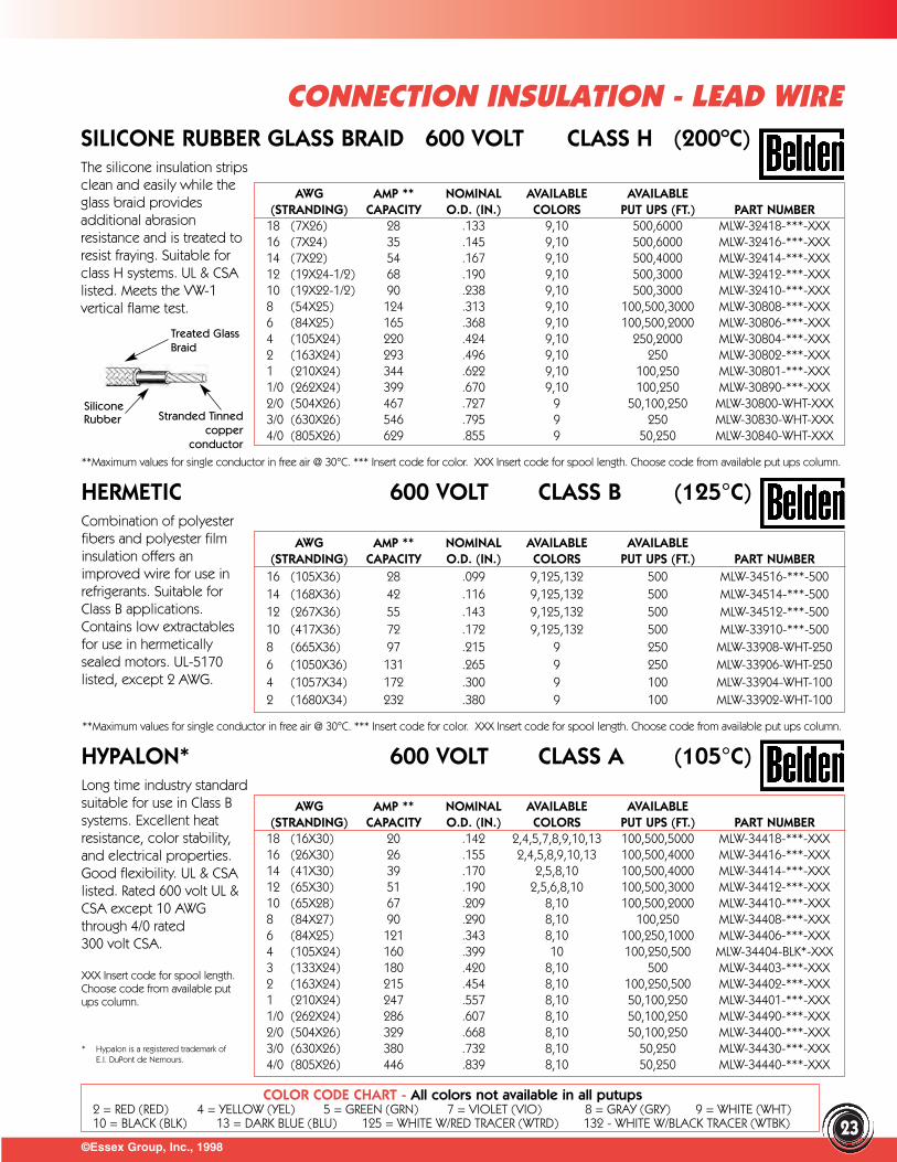
©Essex Group, Inc., 1998
CONNECTION INSULATION - LEAD WIRE
23
SILICONE RUBBER GLASS BRAID 600 VOLT CLASS H (200ºC)The silicone insulation strips clean and easily while theglass braid providesadditional abrasionresistance and is treated toresist fraying. Suitable forclass H systems. UL & CSAlisted. Meets the VW-1vertical flame test.
HERMETIC 600 VOLT CLASS B (125°C)Combination of polyester fibers and polyester filminsulation offers animproved wire for use inrefrigerants. Suitable forClass B applications.Contains low extractablesfor use in hermeticallysealed motors. UL-5170listed, except 2 AWG.
HYPALON* 600 VOLT CLASS A (105°C)Long time industry standard suitable for use in Class Bsystems. Excellent heatresistance, color stability,and electrical properties.Good flexibility. UL & CSAlisted. Rated 600 volt UL &CSA except 10 AWGthrough 4/0 rated 300 volt CSA.
XXX Insert code for spool length.Choose code from available put ups column.
COLOR CODE CHART - All colors not available in all putups2 = RED (RED) 4 = YELLOW (YEL) 5 = GREEN (GRN) 7 = VIOLET (VIO) 8 = GRAY (GRY) 9 = WHITE (WHT)10 = BLACK (BLK) 13 = DARK BLUE (BLU) 125 = WHITE W/RED TRACER (WTRD) 132 - WHITE W/BLACK TRACER (WTBK)
AWG AMP ** NOMINAL AVAILABLE AVAILABLE(STRANDING) CAPACITY O.D. (IN.) COLORS PUT UPS (FT.) PART NUMBER
18 (7X26) 28 .133 9,10 500,6000 MLW-32418-***-XXX16 (7X24) 35 .145 9,10 500,6000 MLW-32416-***-XXX14 (7X22) 54 .167 9,10 500,4000 MLW-32414-***-XXX12 (19X24-1/2) 68 .190 9,10 500,3000 MLW-32412-***-XXX10 (19X22-1/2) 90 .238 9,10 500,3000 MLW-32410-***-XXX8 (54X25) 124 .313 9,10 100,500,3000 MLW-30808-***-XXX6 (84X25) 165 .368 9,10 100,500,2000 MLW-30806-***-XXX4 (105X24) 220 .424 9,10 250,2000 MLW-30804-***-XXX2 (163X24) 293 .496 9,10 250 MLW-30802-***-XXX1 (210X24) 344 .622 9,10 100,250 MLW-30801-***-XXX1/0 (262X24) 399 .670 9,10 100,250 MLW-30890-***-XXX2/0 (504X26) 467 .727 9 50,100,250 MLW-30800-WHT-XXX3/0 (630X26) 546 .795 9 250 MLW-30830-WHT-XXX4/0 (805X26) 629 .855 9 50,250 MLW-30840-WHT-XXX
AWG AMP ** NOMINAL AVAILABLE AVAILABLE(STRANDING) CAPACITY O.D. (IN.) COLORS PUT UPS (FT.) PART NUMBER
16 (105X36) 28 .099 9,125,132 500 MLW-34516-***-50014 (168X36) 42 .116 9,125,132 500 MLW-34514-***-50012 (267X36) 55 .143 9,125,132 500 MLW-34512-***-50010 (417X36) 72 .172 9,125,132 500 MLW-33910-***-5008 (665X36) 97 .215 9 250 MLW-33908-WHT-2506 (1050X36) 131 .265 9 250 MLW-33906-WHT-2504 (1057X34) 172 .300 9 100 MLW-33904-WHT-1002 (1680X34) 232 .380 9 100 MLW-33902-WHT-100
Stranded Tinnedcopper
conductor
Silicone Rubber
Treated GlassBraid
AWG AMP ** NOMINAL AVAILABLE AVAILABLE(STRANDING) CAPACITY O.D. (IN.) COLORS PUT UPS (FT.) PART NUMBER
18 (16X30) 20 .142 2,4,5,7,8,9,10,13 100,500,5000 MLW-34418-***-XXX16 (26X30) 26 .155 2,4,5,8,9,10,13 100,500,4000 MLW-34416-***-XXX14 (41X30) 39 .170 2,5,8,10 100,500,4000 MLW-34414-***-XXX12 (65X30) 51 .190 2,5,6,8,10 100,500,3000 MLW-34412-***-XXX10 (65X28) 67 .209 8,10 100,500,2000 MLW-34410-***-XXX8 (84X27) 90 .290 8,10 100,250 MLW-34408-***-XXX6 (84X25) 121 .343 8,10 100,250,1000 MLW-34406-***-XXX4 (105X24) 160 .399 10 100,250,500 MLW-34404-BLK*-XXX3 (133X24) 180 .420 8,10 500 MLW-34403-***-XXX2 (163X24) 215 .454 8,10 100,250,500 MLW-34402-***-XXX1 (210X24) 247 .557 8,10 50,100,250 MLW-34401-***-XXX1/0 (262X24) 286 .607 8,10 50,100,250 MLW-34490-***-XXX2/0 (504X26) 329 .668 8,10 50,100,250 MLW-34400-***-XXX3/0 (630X26) 380 .732 8,10 50,250 MLW-34430-***-XXX4/0 (805X26) 446 .839 8,10 50,250 MLW-34440-***-XXX
**Maximum values for single conductor in free air @ 30°C. *** Insert code for color. XXX Insert code for spool length. Choose code from available put ups column.
**Maximum values for single conductor in free air @ 30°C. *** Insert code for color. XXX Insert code for spool length. Choose code from available put ups column.
* Hypalon is a registered trademark of E.I. DuPont de Nemours.
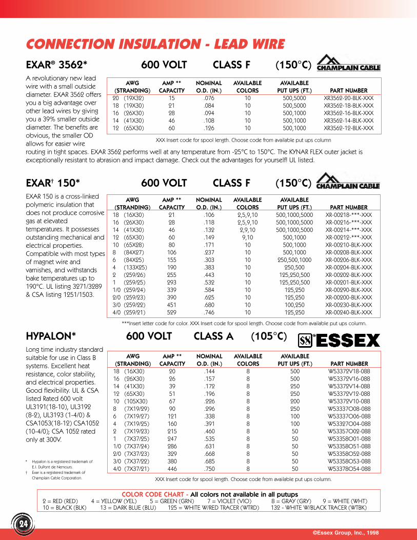
©Essex Group, Inc., 199824
CONNECTION INSULATION - LEAD WIREEXAR® 3562* 600 VOLT CLASS F (150°C)A revolutionary new leadwire with a small outsidediameter. EXAR 3562 offersyou a big advantage overother lead wires by givingyou a 39% smaller outsidediameter. The benefits areobvious, the smaller ODallows for easier wirerouting in tight spaces. EXAR 3562 performs well at any temperature from -25°C to 150°C. The KYNAR FLEX outer jacket isexceptionally resistant to abrasion and impact damage. Check out the advantages for yourself! UL listed.
AWG AMP ** NOMINAL AVAILABLE AVAILABLE(STRANDING) CAPACITY O.D. (IN.) COLORS PUT UPS (FT.) PART NUMBER
20 (19X32) 15 .076 10 500,5000 XR3562-20-BLK-XXX18 (19X30) 21 .084 10 500,5000 XR3562-18-BLK-XXX16 (26X30) 28 .094 10 500,1000 XR3562-16-BLK-XXX14 (41X30) 46 .108 10 500,1000 XR3562-14-BLK-XXX12 (65X30) 60 .126 10 500,1000 XR3562-12-BLK-XXX
EXAR† 150* 600 VOLT CLASS F (150°C)EXAR 150 is a cross-linkedpolymeric insulation thatdoes not produce corrosivegas at elevatedtemperatures. It possessesoutstanding mechanical andelectrical properties.Compatible with most typesof magnet wire andvarnishes, and withstandsbake temperatures up to190°C. UL listing 3271/3289& CSA listing 1251/1503.
AWG AMP ** NOMINAL AVAILABLE AVAILABLE(STRANDING) CAPACITY O.D. (IN.) COLORS PUT UPS (FT.) PART NUMBER
18 (16X30) 21 .106 2,5,9,10 500,1000,5000 XR-00218-***-XXX16 (26X30) 28 .118 2,5,9,10 500,1000,5000 XR-00216-***-XXX 14 (41X30) 46 .132 2,9,10 500,1000,5000 XR-00214-***-XXX 12 (65X30) 60 .149 9,10 500,1000 XR-00212-***-XXX 10 (65X28) 80 .171 10 500,1000 XR-00210-BLK-XXX8 (84X27) 106 .237 10 500,1000 XR-00208-BLK-XXX6 (84X25) 155 .303 10 250,500,1000 XR-00206-BLK-XXX4 (133X25) 190 .383 10 250,500 XR-00204-BLK-XXX2 (259/26) 255 .443 10 125,250,500 XR-00202-BLK-XXX1 (259/25) 293 .532 10 125,250,500 XR-00201-BLK-XXX1/0 (259/24) 339 .584 10 125,250 XR-00290-BLK-XXX2/0 (259/23) 390 .625 10 125,250 XR-00200-BLK-XXX3/0 (259/22) 451 .680 10 100,250 XR-00230-BLK-XXX4/0 (259/21) 529 .746 10 125,250 XR-00240-BLK-XXX
HYPALON* 600 VOLT CLASS A (105°C)Long time industry standardsuitable for use in Class Bsystems. Excellent heatresistance, color stability,and electrical properties.Good flexibility. UL & CSAlisted Rated 600 voltUL3191(18-10), UL3192(8-2), UL3193 (1-4/0) &CSA1053(18-12) CSA1052(10-4/0); CSA 1052 ratedonly at 300V.
AWG AMP ** NOMINAL AVAILABLE AVAILABLE(STRANDING) CAPACITY O.D. (IN.) COLORS PUT UPS (FT.) PART NUMBER
18 (16X30) 20 .144 8 500 W53372V18-08816 (26X30) 26 .157 8 500 W53372V16-08814 (41X30) 39 .172 8 250 W53372V14-08812 (65X30) 51 .196 8 250 W53372V12-08810 (105X30) 67 .226 8 200 W53372V10-0888 (7X19/29) 90 .296 8 250 W53337O08-0886 (7X19/27) 121 .338 8 100 W53337O06-0884 (7X19/25) 160 .391 8 100 W53327O04-0882 (7X19/23) 215 .460 8 50 W53357O02-0881 (7X37/25) 247 .535 8 50 W53358O01-0881/0 (7X37/24) 286 .631 8 50 W53358O51-0882/0 (7X37/23) 329 .668 8 50 W53358O52-0883/0 (7X37/22) 380 .685 8 50 W53358O53-0884/0 (7X37/21) 446 .750 8 50 W53378O54-088
XXX Insert code for spool length. Choose code from available put ups column
***Insert letter code for color. XXX Insert code for spool length. Choose code from available put ups column.
XXX Insert code for spool length. Choose code from available put ups column.
COLOR CODE CHART - All colors not available in all putups2 = RED (RED) 4 = YELLOW (YEL) 5 = GREEN (GRN) 7 = VIOLET (VIO) 8 = GRAY (GRY) 9 = WHITE (WHT)10 = BLACK (BLK) 13 = DARK BLUE (BLU) 125 = WHITE W/RED TRACER (WTRD) 132 - WHITE W/BLACK TRACER (WTBK)
* Hypalon is a registered trademark of E.I. DuPont de Nemours.
† Exar is a registered trademark of Champlain Cable Corporation.
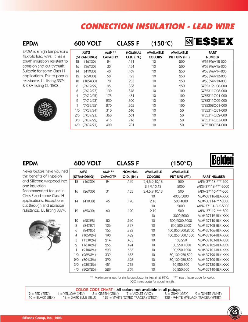
©Essex Group, Inc., 199825
EPDM 600 VOLT CLASS F (150°C)EPDM is a high temperatureflexible lead wire. It has atough insulation resistant toabrasion and cut through.Suitable for some Class Happlications. Fair to poor oilresistance. UL listing 3374& CSA listing CL-1503.
EPDM 600 VOLT CLASS F (150°C)Never before have you had the benefits of Hypalonand Silicone wrapped intoone insulation.Recommended for use inClass F and some Class Happlications. Exceptionalcut through and abrasionresistance. UL listing 3374.
AWG AMP ** NOMINAL AVAILABLE AVAILABLE PART (STRANDING) CAPACITY O.D. (IN.) COLORS PUT UPS (FT.) NUMBER18 (16X30) 24 .141 10 500 W53396V18-00016 (26X30) 30 .154 10 500 W53396V16-00014 (41X30) 40 .169 10 250 W53396V14-00012 (65X30) 50 .193 10 250 W53396V12-00010 (105X30) 70 .253 10 250 W53396V10-0008 (7X19/29) 95 .336 10 250 W35312O08-0006 (7X19/27) 130 .378 10 100 W35311O06-0004 (7X19/25) 175 .431 10 100 W35311O04-0002 (7X19/23) 230 .500 10 100 W35311O02-0001 (7X37/25) 270 .565 10 100 W35308O01-000
1/0 (7X37/24) 310 .610 10 50 W35314O51-0002/0 (7X37/23) 360 .661 10 50 W35314O52-0003/0 (7X37/22) 415 .716 10 50 W35314O53-0004/0 (7X37/21) 490 .781 10 50 W35308O54-000
AWG AMP ** NOMINAL AVAILABLE AVAILABLE(STRANDING) CAPACITY O.D. (IN.) COLORS PUT UPS (FT.) PART NUMBER18 (16X30) 24 .142 2,4,5,9,10,13 500 MLW-37118-***-500
2,4,9,10,13 5000 MLW-37118-***-500016 (26X30) 31 .155 2,4,5,9,10,13 500 MLW-37116-***-500
10 4000,5000 MLW-37116-BLK-XXX14 (41X30) 46 .170 2,10 500,4000 MLW-37114-***-XXX
10 5000 MLW-37114-BLK-500012 (65X30) 60 .190 2,10 500 MLW-37112-***-500
10 3000,5000 MLW-37112-BLK-XXX10 (65X28) 80 .240 10 500,2000,5000 MLW-37110-BLK-XXX8 (84X27) 106 .327 10 250,500,2500 MLW-37108-BLK-XXX6 (84X25) 155 .383 10 100,250,500,2500 MLW-37106-BLK-XXX4 (105X24) 190 .432 10 100,250,500,1000 MLW-37104-BLK-XXX3 (133X24) 214 .453 10 100,250 MLW-37103-BLK-XXX2 (163X24) 255 .494 10 100,250,1000 MLW-37102-BLK-XXX1 (210X24) 293 .583 10 100,250,1000 MLW-37101-BLK-XXX
1/0 (262X24) 339 .633 10 50,100,250,500 MLW-37190-BLK-XXX2/0 (504X26) 390 .698 10 50,100,250,500 MLW-37100-BLK-XXX3/0 (630X26) 451 .758 10 50,250,500 MLW-37130-BLK-XXX4/0 (805X26) 529 .869 10 50,250,500 MLW-37140-BLK-XXX
CONNECTION INSULATION - LEAD WIRE
** Maximum values for single conductor in free air at 30°C. *** Insert letter code for color. XXX Insert code for spool length.
COLOR CODE CHART - All colors not available in all putups2 = RED (RED) 4 = YELLOW (YEL) 5 = GREEN (GRN) 7 = VIOLET (VIO) 8 = GRAY (GRY) 9 = WHITE (WHT)10 = BLACK (BLK) 13 = DARK BLUE (BLU) 125 = WHITE W/RED TRACER (WTRD) 132 - WHITE W/BLACK TRACER (WTBK)
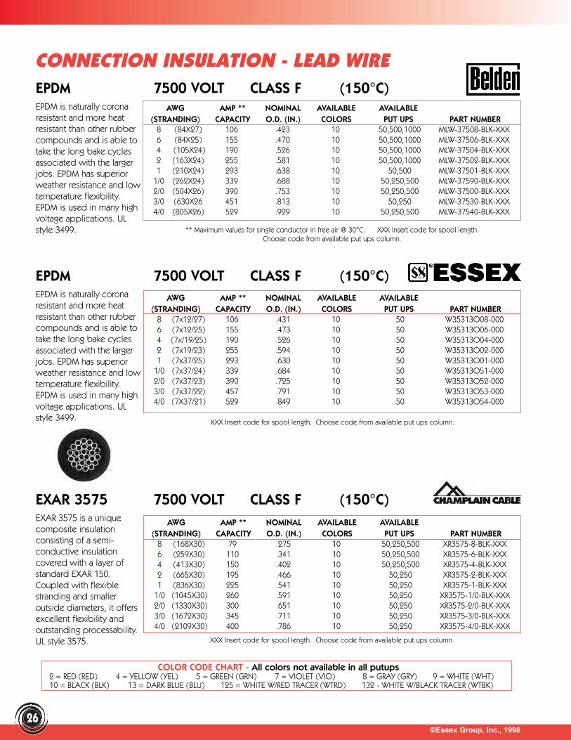
©Essex Group, Inc., 199826
CONNECTION INSULATION - LEAD WIREEPDM 7500 VOLT CLASS F (150°C)EPDM is naturally corona resistant and more heatresistant than other rubbercompounds and is able totake the long bake cyclesassociated with the largerjobs. EPDM has superiorweather resistance and lowtemperature flexibility.EPDM is used in many highvoltage applications. ULstyle 3499.
EPDM 7500 VOLT CLASS F (150°C)EPDM is naturally coronaresistant and more heatresistant than other rubbercompounds and is able totake the long bake cyclesassociated with the largerjobs. EPDM has superiorweather resistance and lowtemperature flexibility.EPDM is used in many highvoltage applications. ULstyle 3499.
EXAR 3575 7500 VOLT CLASS F (150°C)EXAR 3575 is a uniquecomposite insulation consisting of a semi-conductive insulationcovered with a layer ofstandard EXAR 150.Coupled with flexiblestranding and smalleroutside diameters, it offersexcellent flexibility andoutstanding processability. UL style 3575.
AWG AMP ** NOMINAL AVAILABLE AVAILABLE(STRANDING) CAPACITY O.D. (IN.) COLORS PUT UPS PART NUMBER
8 (84X27) 106 .423 10 50,500,1000 MLW-37508-BLK-XXX6 (84X25) 155 .470 10 50,500,1000 MLW-37506-BLK-XXX4 (105X24) 190 .526 10 50,500,1000 MLW-37504-BLK-XXX2 (163X24) 255 .581 10 50,500,1000 MLW-37502-BLK-XXX1 (210X24) 293 .638 10 50,500 MLW-37501-BLK-XXX
1/0 (262X24) 339 .688 10 50,250,500 MLW-37590-BLK-XXX2/0 (504X26) 390 .753 10 50,250,500 MLW-37500-BLK-XXX3/0 (630X26 451 .813 10 50,250 MLW-37530-BLK-XXX4/0 (805X26) 529 .929 10 50,250,500 MLW-37540-BLK-XXX
AWG AMP ** NOMINAL AVAILABLE AVAILABLE(STRANDING) CAPACITY O.D. (IN.) COLORS PUT UPS PART NUMBER
8 (168X30) 79 .275 10 50,250,500 XR3575-8-BLK-XXX6 (259X30) 110 .341 10 50,250,500 XR3575-6-BLK-XXX4 (413X30) 150 .402 10 50,250,500 XR3575-4-BLK-XXX2 (665X30) 195 .466 10 50,250 XR3575-2-BLK-XXX1 (836X30) 225 .541 10 50,250 XR3575-1-BLK-XXX
1/0 (1045X30) 260 .591 10 50,250 XR3575-1/0-BLK-XXX2/0 (1330X30) 300 .651 10 50,250 XR3575-2/0-BLK-XXX3/0 (1672X30) 345 .711 10 50,250 XR3575-3/0-BLK-XXX4/0 (2109X30) 400 .786 10 50,250 XR3575-4/0-BLK-XXX
AWG AMP ** NOMINAL AVAILABLE AVAILABLE(STRANDING) CAPACITY O.D. (IN.) COLORS PUT UPS PART NUMBER
8 (7x12/27) 106 .431 10 50 W35313O08-0006 (7x12/25) 155 .473 10 50 W35313O06-0004 (7x/19/25) 190 .526 10 50 W35313O04-0002 (7x19/23) 255 .594 10 50 W35313O02-0001 (7x37/25) 293 .630 10 50 W35313O01-000
1/0 (7x37/24) 339 .684 10 50 W35313O51-0002/0 (7x37/23) 390 .725 10 50 W35313O52-0003/0 (7x37/22) 457 .791 10 50 W35313O53-0004/0 (7X37/21) 529 .849 10 50 W35313O54-000
** Maximum values for single conductor in free air @ 30°C. XXX Insert code for spool length. Choose code from available put ups column.
XXX Insert code for spool length. Choose code from available put ups column.
XXX Insert code for spool length. Choose code from available put ups column.
COLOR CODE CHART - All colors not available in all putups2 = RED (RED) 4 = YELLOW (YEL) 5 = GREEN (GRN) 7 = VIOLET (VIO) 8 = GRAY (GRY) 9 = WHITE (WHT)10 = BLACK (BLK) 13 = DARK BLUE (BLU) 125 = WHITE W/RED TRACER (WTRD) 132 - WHITE W/BLACK TRACER (WTBK)
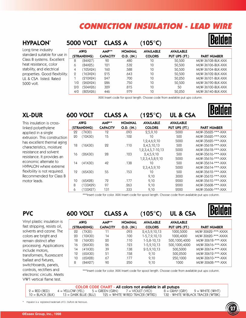
©Essex Group, Inc., 1998
CONNECTION INSULATION - LEAD WIRE
27
HYPALON* 5000 VOLT CLASS A (105°C)Long time industry standard suitable for use inClass B systems. Excellentheat resistance, colorstability, and electricalproperties. Good flexibility.UL & CSA listed. Rated5000 volt.
XL-DUR 600 VOLT CLASS A (125°C) UL & CSAThis insulation is cross-linked polyethyleneapplied in a singleextrusion. This constructionhas excellent thermal agingcharacteristics, moistureresistance and solventresistance. It provides aneconomic alternate toHYPALON where extremeflexibility is not required.Recommended for Class Bmotor leads.
PVC 600 VOLT CLASS A (105°C) UL & CSAVinyl plastic insulation isfast stripping, resists oil,solvents and ozone. Thecolors are bright andremain distinct afterprocessing. Applicationsinclude motors,transformers, fluorescentballast and fixtures,switchboards, panels,controls, rectifiers and electronic circuits. Meets VW1 vertical flame test.
AWG AMP** NOMINAL AVAILABLE AVAILABLE(STRANDING) CAPACITY O.D. (IN.) COLORS PUT UPS (FT.) PART NUMBER
8 (84X27) 90 .480 10 50,500 MLW-36108-BLK-XXX6 (84X25) 121 .532 10 50,500 MLW-36106-BLK-XXX4 (105X24) 160 .588 10 50,500 MLW-36104-BLK-XXX2 (163X24) 215 .643 10 50,500 MLW-36102-BLK-XXX1 (210X24) 247 .700 10 50,250 MLW-36101-BLK-XXX1/0 (262X24) 286 .750 10 50,500 MLW-36190-BLK-XXX2/0 (504X26) 329 .815 10 50 MLW-36100-BLK-XXX4/0 (805X26) 446 .979 10 50,250 MLW-36140-BLK-XXX
AWG AMP** NOMINAL AVAILABLE AVAILABLE(STRANDING) CAPACITY O.D. (IN.) COLORS PUT UPS (FT.) PART NUMBER
22 (7X30) 12 .093 2,5,9,10 5000 MLW-35622-***-XXX20 (10X30) 15 .102 10 500 MLW-35620-***-XXX
1,2,4,6,9,10 5000 MLW-35620-***-XXX18 (16X30) 22 .110 2,4,5,10,13 500 MLW-35618-***-XXX
1,2,3,4,5,7-10,13 5000 MLW-35618-***-XXX16 (26X30) 28 .123 2,4,5,9,10 500 MLW-35616-***-XXX
1,2,3,4,5,8,9,10 5000 MLW-35616-***-XXX14 (41X30) 42 .138 10 500 MLW-35614-***-XXX
2,3,4,5,9,10 5000 MLW-35614-***-XXX12 (65X30) 55 .153 10 500 MLW-35612-***-XXX
9,10 3000 MLW-35612-***-XXX10 (65X28) 72 .177 9,10 2000 MLW-35610-***-XXX8 (133X29) 97 .263 9,10 2000 MLW-35608-***-XXX6 (133X27) 131 .333 9,10 2000 MLW-35606-***-XXX
AWG AMP** NOMINAL AVAILABLE AVAILABLE(STRANDING) CAPACITY O.D. (IN.) COLORS PUT UPS (FT.) PART NUMBER
22 (7X30) 11 .093 2,4,5,9,10,13 1000,5000 MLW-30622-***-XXXX20 (10X30) 14 .100 1-5,7,9,10,13 1000,4000 MLW-30620-***-XXXX18 (16X30) 20 .110 1-5,8-10,13 500,1000,4000 MLW-30618-***-XXX16 (26X30) 26 .123 1-5,9,10,13 500,1000,4000 MLW-30616-***-XXX14 (41X30) 39 .138 2-5,9,10,13 500,5000 MLW-30614-***-XXX12 (65X30) 51 .158 9,10 500,2500 MLW-30612-***-XXX10 (65X28) 67 .177 9,10 250,1000 MLW-30610-***-XXX8 (84X27) 90 .250 9,10 1000 MLW-30608-***-XXX
XXX Insert code for spool length. Choose code from available put ups column.
***Insert code for color. XXX Insert code for spool length. Choose code from available put ups column.
***Insert code for color. XXX Insert code for spool length. Choose code from available put ups column.
COLOR CODE CHART - All colors not available in all putups2 = RED (RED) 4 = YELLOW (YEL) 5 = GREEN (GRN) 7 = VIOLET (VIO) 8 = GRAY (GRY) 9 = WHITE (WHT)10 = BLACK (BLK) 13 = DARK BLUE (BLU) 125 = WHITE W/RED TRACER (WTRD) 132 - WHITE W/BLACK TRACER (WTBK)
* Hypalon is a registered trademark of E.I. DuPont de Nemours.
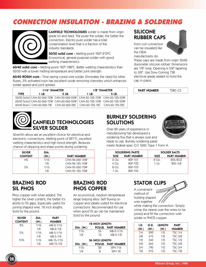
©Essex Group, Inc., 199828
CONNECTION INSULATION - BRAZING & SOLDERINGCANFIELD TECHNOLOGIES solder is made from virgingrade tin and lead. The purer the solder, the better theconnection. Electro pure solder has a totalcontamination level that is a fraction of theindustry standards.
50/50 solid core - Melting point 183º-212ºC.Economical, general purpose solder with goodwetting characteristics.
60/40 solid core - Melting point 183º-188ºC. Better wetting characteristics than50/50 with a lower melting temperature and better joint strength.
60/40 ROSIN core - Time saving cored wire solder. Eliminates the need for otherfluxes, 3% activated rosin has excellent oxide removing chemistry which enhancessolder speed and joint spread.
SILICONERUBBER CAPSForm coil connectioncan be insulated likethe OEMmanufacturers do.These caps are made from virgin 50/60durometer silicone rubber. Dimensionsare 7/8" long. Opening is 5/8" taperingto 3/8". Use Dow Corning 738electrical grade sealant to hold thecap in place.
CANFIELD TECHNOLOGIES SILVER SOLDER
Silver/tin alloys are an excellent choice for electrical andelectronic connections. Melting point of 221°C, excellentwetting characteristics and high bond strength. Reduceschance of dripping and sharp points during soldering.
BURNLEY SOLDERINGSOLUTIONSOver 80 years of experience inmanufacturing has developed asoldering flux that is always sure andready to use. Burnley soldering pastemeets federal spec O.F. 506C Type 1 Form A.
BRAZING RODSIL PHOSPhos copper with silver added. Thehigher the silver content, the better it'sability to fill gaps. Especially useful forjoining shaped wire. 18 inch lengths.Sold by the pound.
BRAZING RODPHOS COPPERAn economical, medium temperaturerange brazing alloy. Self fluxing oncopper and ideally suited for electricalconnections. Recommended for usewhen good fit up can be maintained.Sold by the pound.
1/16” DIAMETER 1/8” DIAMETERTYPE 1 LB. 5 LB. 1 LB. 5 LB.
50/50 Solid CAN-50-062-1SW CAN-50-062-5SW CAN-50-125-1SW CAN-50-125-5SW60/40 Solid CAN-60-062-1SW CAN-60-062-5SW CAN-60-125-1SW CAN-60-125-5SW60/40 Rosin CAN-60-062-1RC CAN-60-062-5RC CAN-60-125-1RC CAN-60-125-5RC
I.D. O.D. LENGTH PART(IN.) (IN.) (IN.) NUMBER1/4 .290 1/2 TSC-1/43/8 .415 1/2 TSC-3/81/2 .540 1/2 TSC-1/25/8 .665 1/2 TSC-5/83/4 .790 1/2 TSC-3/47/8 .915 1/2 TSC-7/8
SILVER DIA.CONTENT (IN.) PART NUMBER
4% 1/16 CAN-96-062-1SW1/8 CAN-96-125-1SW
5% 1/16 CAN-95-062-1SW1/8 CAN-95-125-1SW
SILVER DIA. PARTCONTENT (IN.) NUMBER
2% 1/16 MB-2-1/161/8 MB-2-1/8
5% 1/16 MB-5-1/161/8 MB-5-1/8
15% 1/16 MB-15-1/161/8 MB-15-1/8
18 INCH LENGTHDIA. (IN.) PCS/LB. PART NUMBER
1/16 56 MB-0-1/161/8 16 MB-0-1/8
36 INCH LENGTHDIA. (IN.) PCS/LB. PART NUMBER
1/16 28 SPH-1161/8 8 SPH-18
SOLDERING PASTE SOLDER SALTSSIZE PART NUMBER SIZE PART NUMBER2 Oz. BSP-101 8 Oz. BSS-8OZ4 Oz. BSP-102 1 Lb. BSS-1LB8 Oz. BSP-1031 Lb. BSP-104
PART NUMBER TSRC-C5
STATOR CLIPSA convenient method of holding shaped wire together while making the connection. Simplycrimp the sleeve over the wires to bejoined and fill the connection withsolder or PHOS copper.
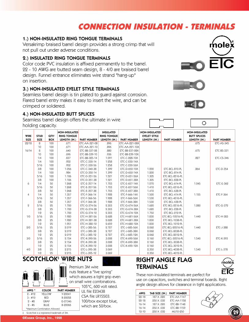
SCOTCHLOK‡ WIRE NUTSPremium 3M wirenuts feature a "live spring”which assures a tight grip evenon small wire combinations.
105°C, 600 volt rated. UL file E23438 CSA file LR15503. 100/box except blue,which are 50/box.
©Essex Group, Inc., 1998
1.) NON-INSULATED RING TONGUE TERMINALSVersakrimp braised barrel design provides a strong crimp that willnot pull out under adverse conditions.
2.) INSULATED RING TONGUE TERMINALSColor code PVC insulation is affixed permanently to the barrel. 22 - 10 AWG are butted seam design, 8 - 4/0 are braised barreldesign. Funnel entrance eliminates wire strand "hang-up"on insertion.
3.) NON-INSULATED EYELET STYLE TERMINALSSeamless barrel design is tin plated to guard against corrosion.Flared barrel entry makes it easy to insert the wire, and can becrimped or soldered.
4.) NON-INSULATED BUTT SPLICESSeamless barrel design offers the ultimate in wireholding capacity.
AWG TAB SIZE (IN.) PART NUMBER22-18 .187 X .020 ETC-AA-114722-18 .250 X .032 ETC-AA-115816-14 .187 X .020 ETC-BB-114816-14 .250 X .032 ETC-BB-115912-10 .250 X .032 MU10-250
AWG * COLOR PART NUMBER2 - #12 YELLOW Y-200413 - #10 RED R-200582 - #8 GRAY G-213462 - #6 BLUE B-20066
*Maximum Combination Allowed
NON-INSULATED INSULATED NON-INSULATED NON-INSULATEDWIRE STUD QTY/ RING TONGUE RING TONGUE EYELET STYLE BUTT SPLICESSIZE SIZE BOX LENGTH (IN.) PART NUMBER LENGTH (IN.) PART NUMBER LENGTH (IN.) PART NUMBER LENGTH (IN.) PART NUMBER22/18 8 100 .671 ETC-AA-321-08 .896 ETC-AA-221-08X .675 ETC-AS-345
10 100 .671 ETC-AA-321-10 .896 ETC-AA-221-10X16/14 8 100 .640 ETC-BB-337-08 .880 ETC-BB-237-08X .675 ETC-BS-331
10 100 .696 ETC-BB-339-10 .936 ETC-BB-239-10X1/4 100 .837 ETC-BB-325-14 1.091 ETC-C-228-10X .827 ETC-CS-3461/4 100 .952 ETC-C-330-14 1.258 ETC-C-230-14X5/16 100 .952 ETC-C-330-56 1.258 ETC-C-230-56X3/8 100 1.056 ETC-C-340-38 1.399 ETC-D-650-10X 1.200 ETC-BCL-810-PL .864 ETC-D-3541/4 100 .984 ETC-D-350-14 1.399 ETC-D-650-14X 1.200 ETC-BCL-814-PL5/16 100 1.106 ETC-D-351-56 1.521 ETC-D-651-56X 1.305 ETC-BCL-8516-PL3/8 100 1.106 ETC-D-351-38 1.521 ETC-D-651-38X 1.305 ETC-BCL-838-PL
6 1/4 50 1.268 ETC-E-357-14 1.703 ETC-E-657-14X 1.270 ETC-BCL-614-PL 1.045 ETC-E-3625/16 50 1.268 ETC-E-357-56 1.703 ETC-E-657-56X 1.410 ETC-BCL-6516-PL3/8 50 1.268 ETC-E-357-38 1.703 ETC-E-657-38X 1.410 ETC-BCL-638-PL
4 1/4 50 1.357 ETC-F-366-14 1.928 ETC-F-666-14X 1.500 ETC-BCL-414-PL 1.155 ETC-F-3645/16 50 1.357 ETC-F-366-56 1.928 ETC-F-666-56X 1.530 ETC-BCL-4516-PL3/8 50 1.357 ETC-F-366-38 1.928 ETC-F-666-38X 1.530 ETC-BCL-438-PL
2 5/16 25 1.700 ETC-G-374-56 2.303 ETC-G-674-56X 1.620 ETC-BCL-2516-PL 1.280 ETC-G-3723/8 25 1.700 ETC-G-374-38 2.303 ETC-G-674-38X 1.620 ETC-BCL-238-PL1/2 25 1.700 ETC-G-374-12 2.303 ETC-G-674-12X 1.750 ETC-BCL-212-PL
1/0 5/16 25 1.920 ETC-H-381-56 2.628 ETC-H-681-56X 1.830 ETC-BCL-10516-PL 1.440 ETC-H-3833/8 25 1.920 ETC-H-381-38 2.628 ETC-H-681-38X 1.830 ETC-BCL-1038-PL1/2 25 1.951 ETC-H-380-12 2.659 ETC-H-680-12X 1.830 ETC-BCL-1012-PL
2/0 5/16 25 2.019 ETC-J-385-56 2.727 ETC-J-685-56X 2.062 ETC-BCL-20516-PL 1.440 ETC-J-3883/8 25 2.019 ETC-J-385-38 2.727 ETC-J-685-38X 2.062 ETC-BCL-2038-PL1/2 25 2.019 ETC-J-385-12 2.727 ETC-J-685-12X 2.062 ETC-BCL-2012-PL
3/0 5/16 25 2.154 ETC-K-390-56 3.008 ETC-K-690-56X 2.160 ETC-BCL-30516-PL 1.540 ETC-K-3933/8 25 2.154 ETC-K-390-38 3.008 ETC-K-690-38X 2.160 ETC-BCL-3038-PL1/2 25 2.154 ETC-K-390-12 3.008 ETC-K-690-12X 2.160 ETC-BCL-3012-PL
4/0 3/8 25 2.215 ETC-L-395-38 3.069 2.350 ETC-BCL-4038-PL 1.540 ETC-L-3781/2 25 2.215 ETC-L-395-12 3.069 2.350 ETC-BCL-4012-PL
CONNECTION INSULATION - TERMINALS
29
RIGHT ANGLE FLAGTERMINALSThese non-insulated terminals are perfect for use on capacitors, switches and terminal boards. Rightangle design allows for clearance in tight applications.
‡ Scotchlok is a registered trademark of 3M.
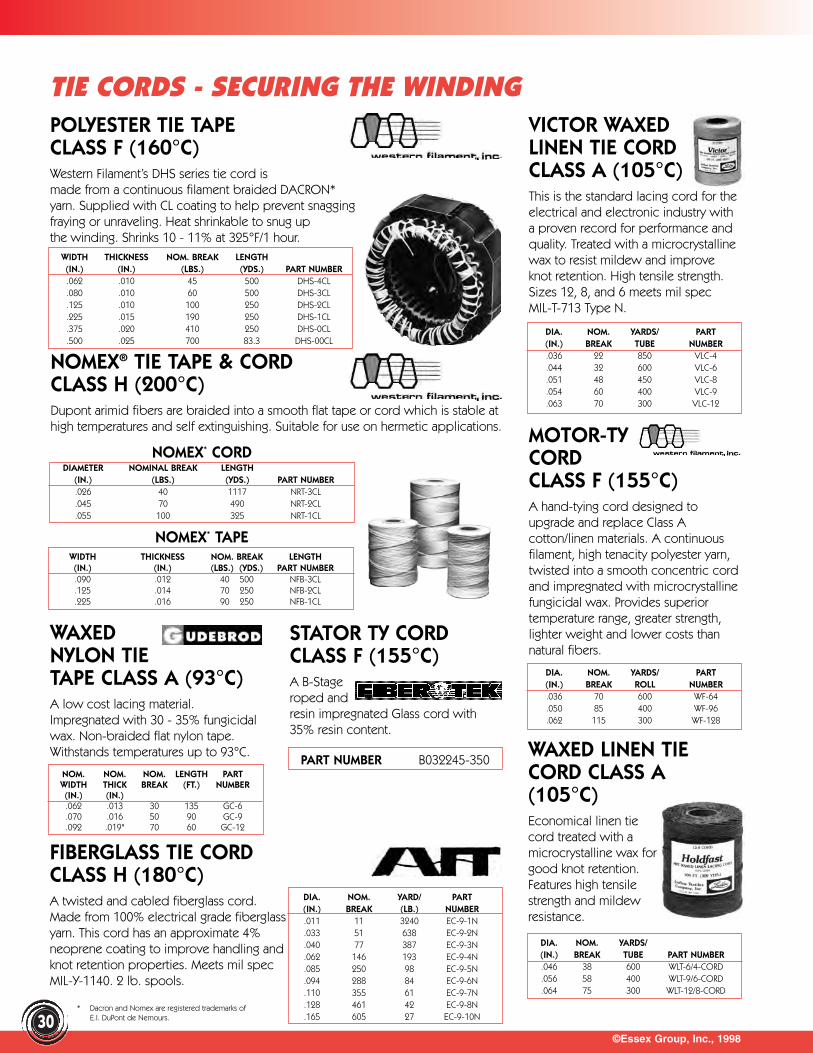
FIBERGLASS TIE CORDCLASS H (180°C)A twisted and cabled fiberglass cord.Made from 100% electrical grade fiberglassyarn. This cord has an approximate 4%neoprene coating to improve handling andknot retention properties. Meets mil specMIL-Y-1140. 2 lb. spools.
©Essex Group, Inc., 199830
TIE CORDS - SECURING THE WINDINGPOLYESTER TIE TAPECLASS F (160°C)Western Filament’s DHS series tie cord is made from a continuous filament braided DACRON*yarn. Supplied with CL coating to help prevent snaggingfraying or unraveling. Heat shrinkable to snug up the winding. Shrinks 10 - 11% at 325°F/1 hour.
WIDTH THICKNESS NOM. BREAK LENGTH(IN.) (IN.) (LBS.) (YDS.) PART NUMBER.062 .010 45 500 DHS-4CL.080 .010 60 500 DHS-3CL.125 .010 100 250 DHS-2CL.225 .015 190 250 DHS-1CL.375 .020 410 250 DHS-0CL.500 .025 700 83.3 DHS-00CL
NOMEX® TIE TAPE & CORDCLASS H (200°C)Dupont arimid fibers are braided into a smooth flat tape or cord which is stable athigh temperatures and self extinguishing. Suitable for use on hermetic applications.
NOMEX* CORDDIAMETER NOMINAL BREAK LENGTH
(IN.) (LBS.) (YDS.) PART NUMBER.026 40 1117 NRT-3CL.045 70 490 NRT-2CL.055 100 325 NRT-1CL
NOMEX* TAPEWIDTH THICKNESS NOM. BREAK LENGTH(IN.) (IN.) (LBS.) (YDS.) PART NUMBER.090 .012 40 500 NFB-3CL.125 .014 70 250 NFB-2CL.225 .016 90 250 NFB-1CL
WAXEDNYLON TIETAPE CLASS A (93°C)A low cost lacing material.Impregnated with 30 - 35% fungicidalwax. Non-braided flat nylon tape.Withstands temperatures up to 93°C.
NOM. NOM. NOM. LENGTH PARTWIDTH THICK BREAK (FT.) NUMBER(IN.) (IN.).062 .013 30 135 GC-6.070 .016 50 90 GC-9.092 .019" 70 60 GC-12
WAXED LINEN TIECORD CLASS A(105°C)Economical linen tiecord treated with amicrocrystalline wax forgood knot retention.Features high tensilestrength and mildewresistance.
DIA. NOM. YARDS/(IN.) BREAK TUBE PART NUMBER.046 38 600 WLT-6/4-CORD.056 58 400 WLT-9/6-CORD.064 75 300 WLT-12/8-CORD
DIA. NOM. YARD/ PART(IN.) BREAK (LB.) NUMBER.011 11 3240 EC-9-1N.033 51 638 EC-9-2N.040 77 387 EC-9-3N.062 146 193 EC-9-4N.085 250 98 EC-9-5N.094 288 84 EC-9-6N.110 355 61 EC-9-7N.128 461 42 EC-9-8N.165 605 27 EC-9-10N
MOTOR-TYCORDCLASS F (155°C)A hand-tying cord designed toupgrade and replace Class Acotton/linen materials. A continuous filament, high tenacity polyester yarn,twisted into a smooth concentric cordand impregnated with microcrystallinefungicidal wax. Provides superior temperature range, greater strength,lighter weight and lower costs than natural fibers.
VICTOR WAXEDLINEN TIE CORDCLASS A (105°C) This is the standard lacing cord for theelectrical and electronic industry witha proven record for performance andquality. Treated with a microcrystallinewax to resist mildew and improveknot retention. High tensile strength.Sizes 12, 8, and 6 meets mil specMIL-T-713 Type N.
DIA. NOM. YARDS/ PART(IN.) BREAK TUBE NUMBER.036 22 850 VLC-4.044 32 600 VLC-6.051 48 450 VLC-8.054 60 400 VLC-9.063 70 300 VLC-12
DIA. NOM. YARDS/ PART(IN.) BREAK ROLL NUMBER.036 70 600 WF-64.050 85 400 WF-96.062 115 300 WF-128
STATOR TY CORDCLASS F (155°C)A B-Stageroped andresin impregnated Glass cord with35% resin content.
PART NUMBER B032245-350
* Dacron and Nomex are registered trademarks of E.I. DuPont de Nemours.
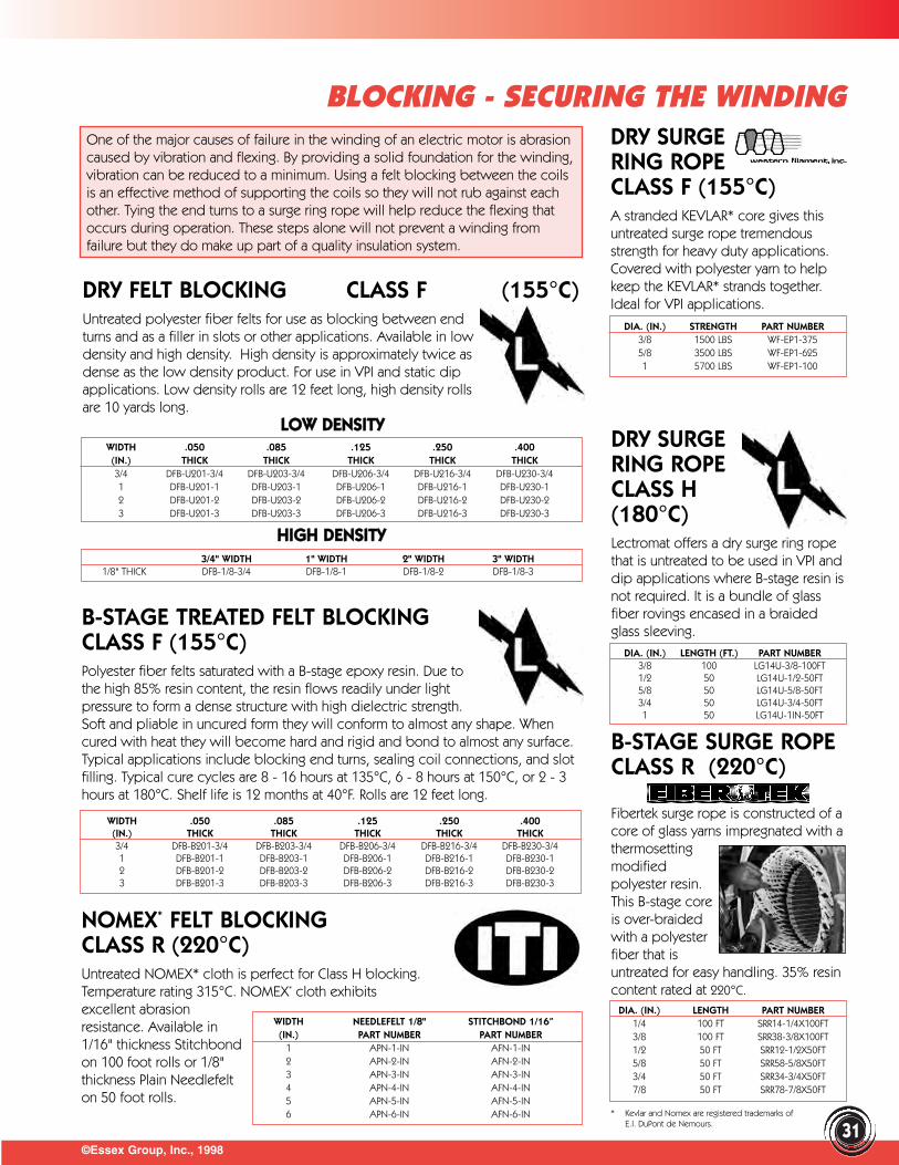
©Essex Group, Inc., 199831
BLOCKING - SECURING THE WINDINGOne of the major causes of failure in the winding of an electric motor is abrasioncaused by vibration and flexing. By providing a solid foundation for the winding, vibration can be reduced to a minimum. Using a felt blocking between the coilsis an effective method of supporting the coils so they will not rub against eachother. Tying the end turns to a surge ring rope will help reduce the flexing thatoccurs during operation. These steps alone will not prevent a winding fromfailure but they do make up part of a quality insulation system.
DRY SURGERING ROPECLASS F (155°C)A stranded KEVLAR* core gives thisuntreated surge rope tremendousstrength for heavy duty applications.Covered with polyester yarn to helpkeep the KEVLAR* strands together.Ideal for VPI applications.
DIA. (IN.) STRENGTH PART NUMBER3/8 1500 LBS WF-EP1-3755/8 3500 LBS WF-EP1-6251 5700 LBS WF-EP1-100
DRY SURGERING ROPECLASS H(180°C)Lectromat offers a dry surge ring ropethat is untreated to be used in VPI anddip applications where B-stage resin isnot required. It is a bundle of glassfiber rovings encased in a braided glass sleeving.
DIA. (IN.) LENGTH (FT.) PART NUMBER3/8 100 LG14U-3/8-100FT1/2 50 LG14U-1/2-50FT5/8 50 LG14U-5/8-50FT3/4 50 LG14U-3/4-50FT1 50 LG14U-1IN-50FT
B-STAGE SURGE ROPECLASS R (220°C)
Fibertek surge rope is constructed of acore of glass yarns impregnated with athermosettingmodifiedpolyester resin.This B-stage coreis over-braidedwith a polyesterfiber that isuntreated for easy handling. 35% resincontent rated at 220°C.
DIA. (IN.) LENGTH PART NUMBER1/4 100 FT SRR14-1/4X100FT3/8 100 FT SRR38-3/8X100FT1/2 50 FT SRR12-1/2X50FT5/8 50 FT SRR58-5/8X50FT3/4 50 FT SRR34-3/4X50FT7/8 50 FT SRR78-7/8X50FT
NOMEX* FELT BLOCKINGCLASS R (220°C)Untreated NOMEX* cloth is perfect for Class H blocking.Temperature rating 315°C. NOMEX* cloth exhibits excellent abrasion resistance. Available in1/16" thickness Stitchbondon 100 foot rolls or 1/8" thickness Plain Needlefelton 50 foot rolls.
WIDTH NEEDLEFELT 1/8" STITCHBOND 1/16”(IN.) PART NUMBER PART NUMBER
1 APN-1-IN AFN-1-IN2 APN-2-IN AFN-2-IN3 APN-3-IN AFN-3-IN4 APN-4-IN AFN-4-IN5 APN-5-IN AFN-5-IN6 APN-6-IN AFN-6-IN
DRY FELT BLOCKING CLASS F (155°C)Untreated polyester fiber felts for use as blocking between endturns and as a filler in slots or other applications. Available in lowdensity and high density. High density is approximately twice asdense as the low density product. For use in VPI and static dipapplications. Low density rolls are 12 feet long, high density rollsare 10 yards long.
LLOOWW DDEENNSSIITTYYWIDTH .050 .085 .125 .250 .400(IN.) THICK THICK THICK THICK THICK3/4 DFB-U201-3/4 DFB-U203-3/4 DFB-U206-3/4 DFB-U216-3/4 DFB-U230-3/41 DFB-U201-1 DFB-U203-1 DFB-U206-1 DFB-U216-1 DFB-U230-12 DFB-U201-2 DFB-U203-2 DFB-U206-2 DFB-U216-2 DFB-U230-23 DFB-U201-3 DFB-U203-3 DFB-U206-3 DFB-U216-3 DFB-U230-3
HHIIGGHH DDEENNSSIITTYY3/4" WIDTH 1" WIDTH 2" WIDTH 3" WIDTH
1/8" THICK DFB-1/8-3/4 DFB-1/8-1 DFB-1/8-2 DFB-1/8-3
B-STAGE TREATED FELT BLOCKINGCLASS F (155°C)Polyester fiber felts saturated with a B-stage epoxy resin. Due tothe high 85% resin content, the resin flows readily under lightpressure to form a dense structure with high dielectric strength.Soft and pliable in uncured form they will conform to almost any shape. Whencured with heat they will become hard and rigid and bond to almost any surface.Typical applications include blocking end turns, sealing coil connections, and slotfilling. Typical cure cycles are 8 - 16 hours at 135°C, 6 - 8 hours at 150°C, or 2 - 3hours at 180°C. Shelf life is 12 months at 40°F. Rolls are 12 feet long.
WIDTH .050 .085 .125 .250 .400(IN.) THICK THICK THICK THICK THICK3/4 DFB-B201-3/4 DFB-B203-3/4 DFB-B206-3/4 DFB-B216-3/4 DFB-B230-3/41 DFB-B201-1 DFB-B203-1 DFB-B206-1 DFB-B216-1 DFB-B230-12 DFB-B201-2 DFB-B203-2 DFB-B206-2 DFB-B216-2 DFB-B230-23 DFB-B201-3 DFB-B203-3 DFB-B206-3 DFB-B216-3 DFB-B230-3
* Kevlar and Nomex are registered trademarks of E.I. DuPont de Nemours.
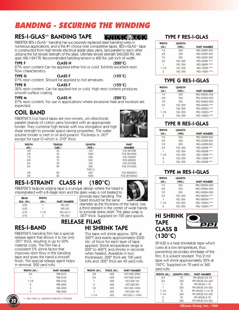
©Essex Group, Inc., 1998
BANDING - SECURING THE WINDING
32
RES-I-GLAS++ BANDING TAPEFIBERTEK RES-I-GLAS++ banding has successively replaced steel banding wires innumerous applications, and is the #1 choice over competitive tapes. RES-I-GLAS++ tapeis constructed from high tensile electrical grade glass yarns, laid parallel to each otherutilizing the full tensile strength of the glass. Ultimate tensile strength 240,000 PSI. Milspec MIL-I-24178. Recommended banding tension is 400 lbs. per inch of width.TYPE F CLASS H (220°C)27% resin content Can be applied either hot or cold. Exhibits excellent resinflow characteristics.TYPE G CLASS F (155°C)27% resin content. Should be applied to hot armatures. TYPE R CLASS F (155°C)32% resin content. Can be applied hot or cold. High resin content producessmooth surface coating.TYPE M CLASS H (220°C)27% resin content. For use in applications where excessive heat and moisture areexpected.
TYPE F RES-I-GLASWIDTH LENGTH(IN.) (YDS.) PART NUMBER1/4 250 FRG-0222F-2503/8 250 FRG-0322F-2501/2 250 FRG-0422F-2503/4 100, 200 FRG-0622F-***1 100, 200 FRG-0822F-***
1-1/2 100, 200 FRG-1222F-***2 100, 200 FRG-1622F-***
TYPE G RES-I-GLASWIDTH LENGTH(IN.) (YDS.) PART NUMBER1/4 250 FRG-0222G-2503/8 250 FRG-0322G-2501/2 250 FRG-0422G-2503/4 100, 200 FRG-0622G-***1 100, 200 FRG-0822G-***
1-1/2 100, 200 FRG-1222G-***2 100, 200 FRG-1622G-***
WIDTH LENGTH(IN.) (YDS) PART NUMBER1/4 250 FRG-0222R-2503/8 250 FRG-0322R-2501/2 250 FRG-0422R-2503/4 100, 200 FRG-0622R-***1 100, 200 FRG-0822R-***
1-1/2 100, 200 FRG-1222R-***2 100, 200 FRG-1622R-***3 100, 200 FRG-2422R-***
WIDTH LENGTH(IN.) (YDS.) PART NUMBER1/4 250 FRG-0222M-2503/8 250 FRG-0322M-2501/2 250 FRG-0422M-2503/4 100, 200 FRG-0622M-***1 100, 200 FRG-0822M-***
1-1/2 100, 200 FRG-1222M-***2 100, 200 FRG-1622M-***
COIL BANDFIBERTEK’S Coil band tapes are non-woven, uni-directional,parallel strands of cotton yarns bonded with an appropriatebinder. They combine high tensile with low elongation and highshear strength to provide space saving properties. The watersoluble binder is inert in oil and pyranol. Thickness is .007"except for type O which is .010" thick.
WIDTH TENSILE LENGTH PART(IN.) (LBS.) (YDS.) NUMBER3/8 45 100 FCB-38100B3/8 45 1000 FCB-381000S1/2 60 500 FCB-12500S5/8 75 500 FCB-58500S3/4 90 100 FCB-34100B3/4 90 500 FCB-341500S
TYPE O3/8 80 500 FCB-38500SO3/8 80 1000 FCB-381000SO
RES-I-STRAINT CLASS H (180°C)FIBERTEK’S tadpole edging tape is a unique design where the bead isimpregnated with a B-stage resin and the glass wrap is not treated to
provide easy handling. Thebead should be the samediameter as the thickness of the band. Usea third restraint in the center of wide bandsto provide stress relief. The glass wrap is.007" thick. Supplied on 100 yard spools.
BEAD WIDTHDIA. (IN.) (IN.) PART NUMBER
3/32 1 FRS-3215/32 1 FRS-5213/16 1-1/2 FRS-361.53/16 3 FRS-363
RELEASE FILMSRES-I-BAND FIBERTEK’S banding film has a specialrelease agent that allows it to be only.001" thick, resulting in up to 50%material costs. The film has aconsistent 5% shrink factor thatimproves resin flow in the bandingtape and gives the band a smoothfinish. The special release agent helpsin removal. 200 yard rolls.
HI SHRINK TAPEThis tape will shrink approx. 20% at300°F and exerts approximately 2500lsb. of force for each layer of tapeapplied. Shrink temperature range is200º to 400°F, and shrinks in secondswhen heated. Available in twothicknesses .002" thick are 100 yardrolls and .005" thick are 40 yard rolls.
WIDTH (IN.) PART NUMBER3/4 FRB-00751 FRB-0100
1-1/2 FRB-01502 FRB-02003 FRB-03004 FRB-0400
WIDTH (IN.) THICK (IN.) PART NUMBER3/8 .002 HST-002-3/8IN3/4 .002 HST-002-3/4IN1 .002 HST-002-1IN2 .002 HST-002-2IN
1/2 .005 HST-005-1/2IN1 .005 HST-005-1IN
1-1/4 .005 HST-005-1-1/4IN
HI SHRINKTAPE CLASS B(130°C) SP-632 is a heat shrinkable tape whichcures at a low temperature, thuspreventing secondary shrinkage of thefilm. It is solvent resistant. This 2 miltape will shrink approximately 30% at150°C. Supplied on 72 yard or 360yard rolls.WIDTH (IN.) LENGTH (YDS.) PART NUMBER
3/4 72 PPI-SP632-3/4-723/4 360 PPI-SP632-3/4-3601 72 PPI-SP632-1-721 360 PPI-SP632-3/4-360
1-1/4 72 PPI-SP632-1-1/4-721-1/4 360 PPI-SP632-3/4-360
2 72 PPI-SP632-2-722 360 PPI-SP632-3/4-360
TYPE R RES-I-GLAS
TYPE M RES-I-GLAS
++ Res-I-Glas is a registered trademark of Fibertek.
CLEAR MASKINGCOMPOUNDThis polymer resinprevents adhesion ofDolph solventless resins. Thiscompound is designed to coat metalsubstrates and mask surfaces fromadhesion of solventless polyesters andcompounds. Easy to apply bybrushing or dipping. Peels off easilyleaving metal surfaces clean of varnish.Drys at room temperature in 15-45minutes, or at 200ºF - 2-5 minutes.
©Essex Group, Inc., 1998
FINAL INSULATION - MASKING COMPOUNDS & GREASES
SPRAYONSPRAYVARNISH RELEASEAGENTSpray onto the surface thatyou don’t want varnish toadhere to, it dries quickly.Once the dip and bakeprocess has been completed,the coating can be easilyremoved. Dry Film P.T.F.E. withKrytox. Exceptional anti-stickproperties resist transferring to finishedparts. Multiple releases perapplication.
BLUE MASKING VARNISH
A blue masking varnish that does notadhere to metal surfaces. Forms aquick drying film that can be easilystripped off later. Dries in 5-15 minutesat room temperature. Apply with adisposable brush.
YELLOWMASKINGCOMPOUNDThe bright yellow color is highly visibleunder varnishes. Apply with a brush orknife to approx. a 5-10 mil thickness.Brush or apply in one direction, avoidback and forth strokes. A good rule ofthumb is to obscure the surface beingcoated. Allow to dry 30 minutes beforeapplying varnish treatments. Once thevarnish is cured, the coating can beremoved by scoring with a wood stickor rod. Clean threads by running a nutor a tap over the threaded areas.Withstands bake temperature up to392°F for 1-1/4 hours.
MASKING TIPBy using a release agent or maskingcompound, clean up time can begreatly reduced. The varnish will bemuch easier to remove from surfacesthat you do not want the varnish toadhere to, ex.: threaded holes, endbell fits, etc.
FAMOUS MASKING COMPOUNDA viscous hightemperature-resistantgrease designed tofacilitate the easyremoval of curedvarnish from metalsurfaces. Highly resistant to solventsand will not contaminate varnishes if itaccidentally gets into the dip tank.Famous masking compound does notcure with heat but withstandstemperatures up to 500°F. Apply athick coating of compound to areasthat you don’t want the varnish toadhere to, varnish application can bedone immediately, as there is no curecycle. After varnish treatment, removevarnish and compound with puttyknife or spatula.
VERTICAL MASKINGCOMPOUND (Thermosetting)Paste-like maskingcompound for vertical surfaces andirregular surfaces. Can be applied tohot or cold surfaces with a putty knifeor caulking gun. The film must becured at 275ºF for 20-30 minutes,before being subjected to varnish,lacquers, solvents.
GAP FILLINGCOMPOUND
When mounting field coils on polepieces, it is important to fill the gapsbetween the pole piece and field coilto insure good thermal conductivity.These compounds also havemechanical strength due to their highadhesive properties. B-7-302 has aslightly higher viscosity to provide ahigher build. Both products exhibithigh adhesive properties. Rated up to150°C temperature rating. Cure cycle is2-6 hours @ 275º-300°F, depending ondepth of material to be cured.
CONTAINER PART NUMBER1 Gallon MN-743-1
CONTAINER PART NUMBER16 oz. SPN-811
CONTAINER PART NUMBER1 Gallon MY-739-1
CONTAINER PART NUMBER1 Gallon B-213-1GAL
CONTAINER PART NUMBER10 lbs. FMC-1035 lbs. FMC-35120 lbs. FMC-120
CONTAINER PART NUMBER1 Gallon CC-1022-15 Gallon CC-1022-5
CONTAINER PART NUMBER1 Gallon B-7-300-10LB5 Gallon B-7-300-5GAL55 Gallon B-7-302-55GAL
33
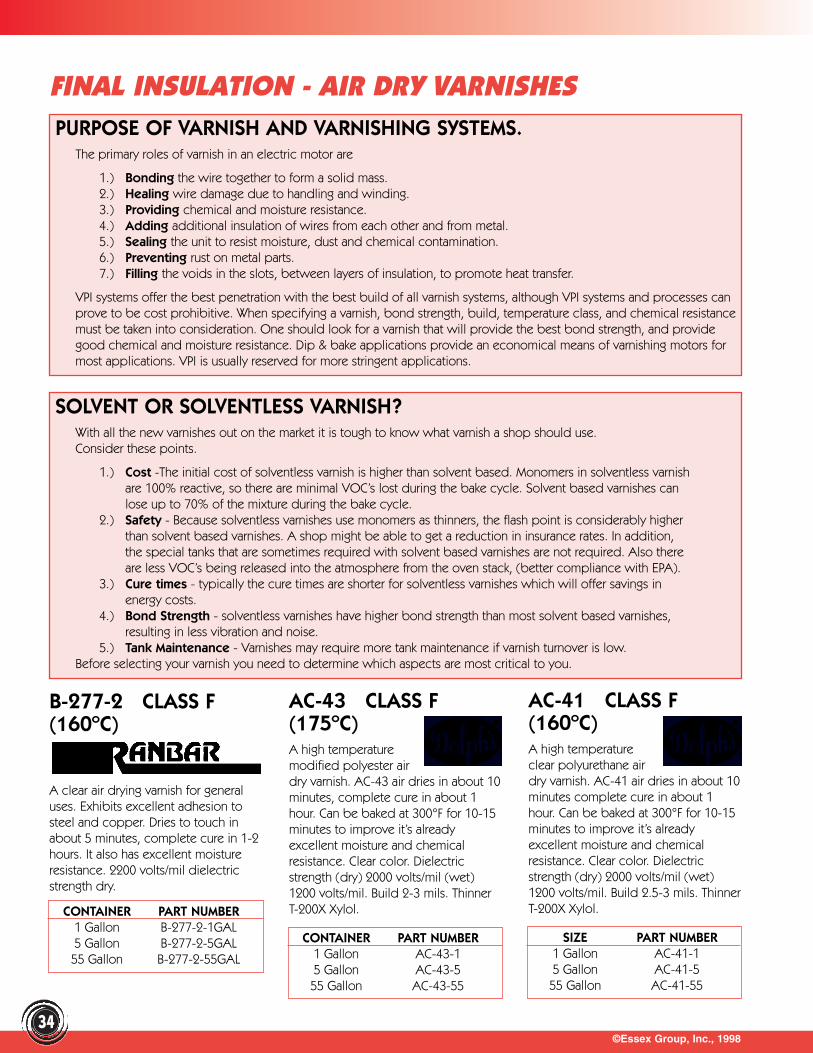
©Essex Group, Inc., 199834
FINAL INSULATION - AIR DRY VARNISHESPURPOSE OF VARNISH AND VARNISHING SYSTEMS.
The primary roles of varnish in an electric motor are
1.) Bonding the wire together to form a solid mass. 2.) Healing wire damage due to handling and winding. 3.) Providing chemical and moisture resistance. 4.) Adding additional insulation of wires from each other and from metal. 5.) Sealing the unit to resist moisture, dust and chemical contamination. 6.) Preventing rust on metal parts. 7.) Filling the voids in the slots, between layers of insulation, to promote heat transfer.
VPI systems offer the best penetration with the best build of all varnish systems, although VPI systems and processes canprove to be cost prohibitive. When specifying a varnish, bond strength, build, temperature class, and chemical resistancemust be taken into consideration. One should look for a varnish that will provide the best bond strength, and providegood chemical and moisture resistance. Dip & bake applications provide an economical means of varnishing motors formost applications. VPI is usually reserved for more stringent applications.
SOLVENT OR SOLVENTLESS VARNISH?With all the new varnishes out on the market it is tough to know what varnish a shop should use.Consider these points.
1.) Cost -The initial cost of solventless varnish is higher than solvent based. Monomers in solventless varnish are 100% reactive, so there are minimal VOC’s lost during the bake cycle. Solvent based varnishes can lose up to 70% of the mixture during the bake cycle.
2.) Safety - Because solventless varnishes use monomers as thinners, the flash point is considerably higher than solvent based varnishes. A shop might be able to get a reduction in insurance rates. In addition, the special tanks that are sometimes required with solvent based varnishes are not required. Also there are less VOC’s being released into the atmosphere from the oven stack, (better compliance with EPA).
3.) Cure times - typically the cure times are shorter for solventless varnishes which will offer savings in energy costs.
4.) Bond Strength - solventless varnishes have higher bond strength than most solvent based varnishes, resulting in less vibration and noise.
5.) Tank Maintenance - Varnishes may require more tank maintenance if varnish turnover is low.Before selecting your varnish you need to determine which aspects are most critical to you.
B-277-2 CLASS F(160ºC)
A clear air drying varnish for generaluses. Exhibits excellent adhesion tosteel and copper. Dries to touch inabout 5 minutes, complete cure in 1-2hours. It also has excellent moistureresistance. 2200 volts/mil dielectricstrength dry.
AC-43 CLASS F(175ºC)A high temperaturemodified polyester airdry varnish. AC-43 air dries in about 10minutes, complete cure in about 1hour. Can be baked at 300°F for 10-15minutes to improve it’s alreadyexcellent moisture and chemicalresistance. Clear color. Dielectricstrength (dry) 2000 volts/mil (wet)1200 volts/mil. Build 2-3 mils. ThinnerT-200X Xylol.
AC-41 CLASS F(160ºC)A high temperatureclear polyurethane airdry varnish. AC-41 air dries in about 10minutes complete cure in about 1hour. Can be baked at 300°F for 10-15minutes to improve it’s alreadyexcellent moisture and chemicalresistance. Clear color. Dielectricstrength (dry) 2000 volts/mil (wet)1200 volts/mil. Build 2.5-3 mils. ThinnerT-200X Xylol.CONTAINER PART NUMBER
1 Gallon B-277-2-1GAL5 Gallon B-277-2-5GAL55 Gallon B-277-2-55GAL
CONTAINER PART NUMBER1 Gallon AC-43-15 Gallon AC-43-555 Gallon AC-43-55
SIZE PART NUMBER1 Gallon AC-41-15 Gallon AC-41-555 Gallon AC-41-55
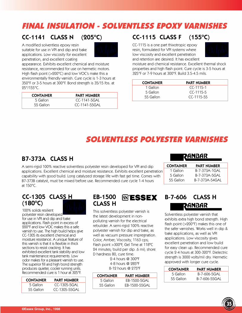
©Essex Group, Inc., 1998
FINAL INSULATION - SOLVENTLESS EPOXY VARNISHES
35
CC-1141 CLASS N (205ºC)A modified solventless epoxy resinsuitable for use in VPI and dip and bakeapplications. Low viscosity for excellentpenetration, and excellent coatingappearance. Exhibits excellent chemical and moistureresistance, recommended for use on hermetic motors.High flash point (>200°C) and low VOC’s make this aenvironmentally friendly varnish. Cure cycle is 1-3 hours at350°F or 3-5 hours at 300°F. Bond strength is 35/15 lbs. at25°/155°C.
CC-1115 CLASS F (155ºC)CC-1115 is a one part thixotropic epoxyresin, formulated for VPI systems wherelow viscosity and excellent penetrationand retention are desired. It has excellentmoisture and chemical resistance. Excellent thermal shockproperties and high flash point. Cure cycle is 3-5 hours at325°F or 7-9 hours at 300°F. Build 3.5-4.5 mils.
B7-373A CLASS HA semi-rigid 100% reactive solventless polyester resin developed for VPI and dipapplications. Excellent chemical and moisture resistance. Exhibits excellent penetrationcapability with good build. Long catalyzed storage life with fast gel time. Comes withB7-373B catalyst, must be mixed before use. Recommended cure cycle 1-4 hours at 150°C.
B-7-606 CLASS H
Solventless polyester varnish thatexhibits extra high bond strength. Highflash point (>200°F) makes this one ofthe safer varnishes. Works well in dip &bake applications, as well as VPIapplications. Low viscosity givesexcellent penetration and low buildfor easy clean up. Recommended curecycle 2-4 hours at 300-320°F. Dielectricstrength is 3000 volts/mil dry. Hermeticapproved with longer cure cycle.
EB-1500CLASS HThis solventless polyester varnish isthe latest development in non-polluting varnish for the electricalrebuilder. A semi-rigid 100% reactivepolyester varnish for dip and bake, aswell as vacuum pressure impregnation.Color, Amber; Viscosity, 1163 cps;Flash point >300ºF, Gel Time at 118ºC24 minutes; build per dip .6 mil; shoreD hardness 80, cure time:
2-4 hours @ 300ºF4-8 hours @ 285ºF8-12 hours @ 275ºF
CC-1305 CLASS H(180ºC)100% solids resilient polyester resin developed for use in VPI and dip and bakeapplications. Flash point in excess of200°F and low VOC makes this a safevarnish to use. The high build helps giveCC-1305 its excellent chemical andmoisture resistance. A unique feature ofthis varnish is that it is flexible in thicksections to resist cracking. It hasexhibited excellent tank stability and lowtank maintenance requirements. Lowodor makes for a pleasant varnish to use.The superior fill and high bond strengthproduces quieter, cooler running units.Recommended cure is 1 hour at 325°F.
CONTAINER PART NUMBER5 Gallon CC-1141-5GAL55 Gallon CC-1141-55GAL
CONTAINER PART NUMBER1 Gallon CC-1115-15 Gallon CC-1115-555 Gallon CC-1115-55
CONTAINER PART NUMBER1 Gallon B-7-373A-1GAL5 Gallon B-7-373A-5GAL55 Gallon B-7-373A-54GAL
CONTAINER PART NUMBER5 Gallon B-7-606-5GAL55 Gallon B-7-606-55GAL
CONTAINER PART NUMBER5 Gallon EB-1500-5GAL55 Gallon EB-1500-55GAL
SOLVENTLESS POLYESTER VARNISHES
CONTAINER PART NUMBER5 Gallon CC-1305-5GAL55 Gallon CC-1305-55GAL

©Essex Group, Inc., 199836
FINAL INSULATION - AIR DRY VARNISHESFUNGUSRESISTANTAC-46 CLASS F (160ºC)High temperature polyurethaneelectrical insulation that dries veryquickly to a tough clear, chemicallyresistant film. Clear color. AC-46 airdries in about 10 minutes completecure in about 1 hour, can be baked at300°F for 10-15 minutes to improve it’salready excellent moisture andchemical resistance. Dielectric strength(dry) 2000 volts/mil (wet) 1200volts/mil. Build 2.5-3 mils. Thinner T-200X Xylol.
30 REDPROTECTIVESEALERPedigree No. 30 prevents underlyinginsulation windings from beingattacked by oils, greases, gas, acid,alkalids or water. It assures completecover if applied carefully by dipping,spraying or brushing. Its smoothappearance is tough, withstandingconsiderable abuse when electricalapparatus is in operation. It is flexible,heat and arc resistant, dust repellent.Best air drying results, dip unitsbetween 120°F to 130°F unittemperature.
434-66 AND434-66 BLACK(220ºC)High temperature electrical insulationthat dries very quickly to a tough, clearamber, moisture resistant film. Alsoavailable in black. Air dries in about15 minutes, complete cure in about1 hour, can be baked at 250°F for2 hours to improve its alreadyexcellent moisture resistance. Dielectricstrength (dry) 3140 volts/mil (wet) 2600volts/mil. Bond Strength .7 at 150°C.
77X-010 AIR DRY UL THERMAL CLASS 130 THROUGH 180A clear, fast drying or low temperature cure insulating varnish forimpregnating and seal coating of electrical apparatus. Excellentmoisture and chemical resistance. Color amber, flash point 70ºC,Dielectric strength (dry) 4000 volts/mil, (wet) 2680 volts/mil.
E-900-LV/900-T CLASS H (180ºC)A single component solventless epoxyresin for use in VPI or dip and bakeapplications. Two types available, lowviscosity is for use in form wound coilsand transformers and thixotropic foruse on random wound coils thatrequire a higher build. This resin offersoutstanding bond strength, chemicalresistance and physical properties.Whether the application requires lowviscosity for better penetration orthixotropic for higher build, E-900LVgives you the resin to suit your needs.Flash point is >250°F. Recommendedcure cycle is 2-4 hours at 325° to 350°F.Bond strength is 47.9/4.4 lbs. at25°/150°C.
B-7-619CLASS H (180ºC)
A single part 100% reactive epoxyresin specially designed for superiorperformance in VPI systems. Meetsmine, navel, and nuclear plantapproval. Low viscosity enhancesperformance by providing excellentpenetration in form coil applications.Slightly thixotropic to give completeand void-free impregnation in randomwound equipment. Dielectric strength2760 volts/ mil. Cure cycle 4-6 hours at150°-160°C. Bond strength is 67/6.7lbs. at 25°/150°C.
CC-1118-LVCLASS HA unique, one part, thixotropic epoxyresin for use where high voltage, lowcorona, superior chemical resistance,and excellent electrical insulationproperties at elevated temperatures arerequired. Allows dipping attemperature in excess of 150° toimprove impregnation and shortenprocess time. Thixotropic givesexcellent penetration and completeencapsulation. Exhibits exceptional tankstability. Routine tank maintenance andcooling not required. Meets mil specMIL-M-1760E. Specifically formulatedfor VPI, yet works in dip applicationstoo. Cure cycle 4-6 hours at 325°F formaximum chemical resistance.
CONTAINER PART NUMBER1 Gallon AC-46-15 Gallon AC-46-555 Gallon AC-46-55
CONTAINER PART NUMBER1 Gallon H30015 Gallon H300555 Gallon H3055
CONTAINER PART NUMBER1 Gallon H434015 Gallon H4340555 Gallon H434551 Gallon H434B01 (Black)5 Gallon H434B05 (Black)55 Gallon H434B55 (Black)
CONTAINER PART NUMBER1 Gallon H77X010015 Gallon H77X0100555 Gallon H77X01055
FINAL INSULATION - SOLVENTLESS EPOXY VARNISHES
CONTAINER PART NUMBER5 Gallon HE900LV0555 Gallon HE900LV555 Gallon HE900T05 (Thixo)55 Gallon HE900T55 (Thixo)
CONTAINER PART NUMBER5 Gallon B-7-619-5GAL
55 Gallon B-7-619-50GAL55 Gallon B-7-619LV-55GAL
(Low Viscosity)
CONTAINER PART NUMBER1 Gallon CC-1118LV-15 Gallon CC-1118LV-555 Gallon CC-1118LV-55
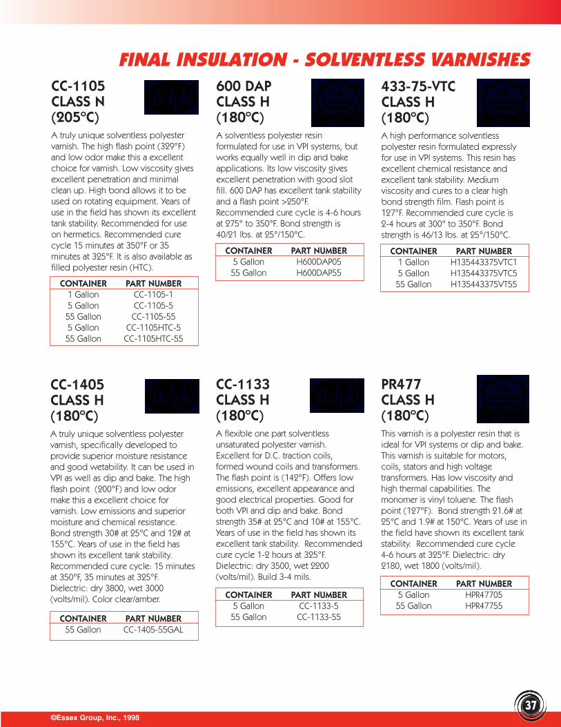
©Essex Group, Inc., 199837
FINAL INSULATION - SOLVENTLESS VARNISHESCC-1105CLASS N (205ºC)A truly unique solventless polyestervarnish. The high flash point (329°F)and low odor make this a excellentchoice for varnish. Low viscosity givesexcellent penetration and minimalclean up. High bond allows it to beused on rotating equipment. Years ofuse in the field has shown its excellenttank stability. Recommended for useon hermetics. Recommended curecycle 15 minutes at 350°F or 35minutes at 325°F. It is also available asfilled polyester resin (HTC).
600 DAP CLASS H (180ºC)A solventless polyester resinformulated for use in VPI systems, butworks equally well in dip and bakeapplications. Its low viscosity givesexcellent penetration with good slotfill. 600 DAP has excellent tank stabilityand a flash point >250°F.Recommended cure cycle is 4-6 hoursat 275° to 350°F. Bond strength is40/21 lbs. at 25°/150°C.
433-75-VTCCLASS H (180ºC)A high performance solventlesspolyester resin formulated expresslyfor use in VPI systems. This resin hasexcellent chemical resistance andexcellent tank stability. Mediumviscosity and cures to a clear highbond strength film. Flash point is127°F. Recommended cure cycle is2-4 hours at 300° to 350°F. Bondstrength is 46/13 lbs. at 25°/150°C.
CC-1133CLASS H (180ºC)A flexible one part solventlessunsaturated polyester varnish.Excellent for D.C. traction coils,formed wound coils and transformers.The flash point is (142°F). Offers lowemissions, excellent appearance andgood electrical properties. Good forboth VPI and dip and bake. Bondstrength 35# at 25°C and 10# at 155°C.Years of use in the field has shown itsexcellent tank stability. Recommendedcure cycle 1-2 hours at 325°F.Dielectric: dry 3500, wet 2200(volts/mil). Build 3-4 mils.
CC-1405CLASS H(180ºC)A truly unique solventless polyestervarnish, specifically developed toprovide superior moisture resistanceand good wetability. It can be used inVPI as well as dip and bake. The highflash point (200°F) and low odormake this a excellent choice forvarnish. Low emissions and superiormoisture and chemical resistance.Bond strength 30# at 25°C and 12# at155°C. Years of use in the field hasshown its excellent tank stability.Recommended cure cycle: 15 minutesat 350°F, 35 minutes at 325°F.Dielectric: dry 3800, wet 3000(volts/mil). Color clear/amber.
PR477CLASS H (180ºC)This varnish is a polyester resin that isideal for VPI systems or dip and bake.This varnish is suitable for motors,coils, stators and high voltagetransformers. Has low viscosity andhigh thermal capabilities. Themonomer is vinyl toluene. The flashpoint (127°F). Bond strength 21.6# at25°C and 1.9# at 150°C. Years of use inthe field have shown its excellent tankstability. Recommended cure cycle 4-6 hours at 325°F. Dielectric: dry2180, wet 1800 (volts/mil).
CONTAINER PART NUMBER1 Gallon CC-1105-15 Gallon CC-1105-555 Gallon CC-1105-555 Gallon CC-1105HTC-555 Gallon CC-1105HTC-55
CONTAINER PART NUMBER5 Gallon H600DAP05
55 Gallon H600DAP55
CONTAINER PART NUMBER1 Gallon H135443375VTC15 Gallon H135443375VTC555 Gallon H135443375VT55
CONTAINER PART NUMBER55 Gallon CC-1405-55GAL
CONTAINER PART NUMBER5 Gallon CC-1133-555 Gallon CC-1133-55
CONTAINER PART NUMBER5 Gallon HPR4770555 Gallon HPR47755
BC-352 CLASS H(180ºC)A one part, highbond strength, clearepoxy varnish that offers the highestresistance to chemicals, solventsand moisture. Provides protection towindings that must operate incorrosive conditions. Recommendedfor hermetic motors in fluorinatedrefrigerants, as well as stators,armatures, laminations and rotatingfield coils. Dielectric: dry 4600, wet3600. Recommended cure cycle 2-4
hours at 300ºF. Build 3-4 mils.(See Part Numbers to right.)
CONTAINER PART NUMBER1 Gallon BEI-915A-5GAL15 Gallon BEI-915A-15GAL55 Gallon BEI-915A-55GAL
CONTAINER PART NUMBER1 Gallon BC-359-15 Gallon BC-359-555 Gallon BC-359-55
CONTAINER PART NUMBER1 Gallon BC-346A-15 Gallon BC-346A-555 Gallon BC-346A-55
©Essex Group, Inc., 199838
FINAL INSULATION - SOLVENT BASED VARNISHB-346A CLASS N(215ºC)A specially formulatedsolvent-based polyestervarnish for use in up to Class H systems.For a low price, BC-346A will give highbuild with excellent flexibility. It exhibitsexcellent moisture and chemicalresistance. Meets Mil spec MIL-I-24092/D.Excellent for use in transformers, stators,form coils and random wound coils.Dielectric: dry 4,000, wet 2,900(volts/mil) Recommended cure cycle1-2 hours at 325°F, 2-1/2-5 hours at 275ºF.Build 4-5 mils.
BC-359 CLASS H(180ºC)A versatile cure cyclemakes this solventbased varnish truly unique, a fast curecan be obtained at low temperatureor an ultra fast cure at hightemperature. Provides superiormoisture resistance and excellentchemical and abrasion resistance. Lowcost and meets Rule 66 air pollutionstandards. Excellent for motors, relays,transformers, stators, form wound coilsand random wound coils. Dielectricstrength: dry/wet: 3000 volt/mil.Recommended cure cycle 1/2-1-1/2hours at 325°F or 8-10 hours at 230°F.
BEI-915A CLASS HA low-heatcure modifiedpolyester-solvent base, clear bakingvarnish. Retains its light amber color forwell over a year and gives off virtuallyno odor. Exhibits excellent oil andmoisture resistance, high bond strengthand excellent adhesion. Dielectricstrength is 4400 volts/mil when dry. Aclassic dip & bake varnish thatconserves energy because of its fastcure cycle. Recommended cure cycle2-4 hours at 250-275°F.
Y-210 CLASS H (180ºC)A general purpose solvent based modified polyester varnish that is an industry standard for a variety of applications. Typical uses includestator, coil and transformerimpregnation. Meets mil specMIL-I-24092. Flash point is 85ºF.Recommended cure cycle is 2-4 hoursat 300º-350ºF. Bond strength is 27/2.7lbs. at 25°/150°C. Uses Xylol thinner.
711-F2106CLASS H (180ºC)A solvent-basedmodified polyestervarnish that is widelyaccepted throughout theelectrical industry. Its longlife, ease of maintenance and applicationhas made it a successful varnish for manyyears. Medium viscosity provides goodpenetration and good film build. Meetsmil spec MIL-I-24092. Flash point is 55°F.Recommended cure cycle is 2-6 hours at300°-350°F. Bond strength is 20.8/1 lbs.at 25°/150°C.
®
CONTAINER PART NUMBER1 Gallon H7112106015 Gallon H71121060555 Gallon H711210655
CONTAINER PART NUMBER5 Gallon HY2100555 Gallon HY21055
CONTAINER PART NUMBER5 Gallon HY210M0555 Gallon HY210M55
923 EPOXY HERMETIC INSULATION VARNISHIt is the varnish of choice by the refrigeration compressor industry. Along with itsexcellent freon resistance, it isimpervious to harsh chemicalenvironments. The product is availablein both 35% and 50% solids (byweight) for customer convenience. Highbond strengths, low to mediumviscosity, excellent tank stability. Color isclear amber. Flash point for 35% 83ºFand 50% 94ºF. Dielectric strength: dry4000 volt/mil, wet 3200 volts/mil. Bondstrength is 35.3/6.7 lbs. at 25°/150°C.
CONTAINER PART NUMBER - 35%CONTAINER PART NUMBER - 50%
1 Gallon H92335015 Gallon H923350555 Gallon H92335551 Gallon H92350015 Gallon H923500555 Gallon H9235055
CONTAINER PART NUMBER1 Gallon BC-352-15 Gallon BC-352-555 Gallon BC-352-55
LOW VOC Y-210M CLASS H (180ºC)This is a low VOC compliant varnish, with high solids. It is a general purpose solvent based modified polyester varnish that is anindustry standard for a variety ofapplications. Typical uses include stator,coil and transformer impregnation.Meets mil spec MIL-I-24092. Flash pointis 80ºF. Recommended cure cycle is2-10 hours at 300º- 350ºF. Bond strengthis 22.7/1.9 lbs. at 25°/200°C. Dielectric:3440/ 3050 (volts/mil). Build 1.15 mils.Uses thinner Oxsol-100 (OX100).
©Essex Group, Inc., 199839
FINAL INSULATION
DC 997 CLASS RSilicone resin varnish that exhibits excellent bond strength even at high temperatures.Contains excellent electrical properties and moisture resistance. Easy to use. Meetsmil spec MIL-I-24092B. Flash point 80ºF. Initial cure cycle 2-4 hours at 302º - 392ºF. Ifequipment is to be operated at temperatures higher than 200ºC, should be given anadditional cure of 6 hours at 482ºF.
Clear insulating varnish. Thoroughly penetrates old and new material, airdries faster than most insulating aerosols.Provides high adhesion, high arc-resistance and non-trackingproperties. • Air Dries in 10-15 minutes; tack free in 60 minutes.• Use as insulating varnish in Class F applications, as well as a topcoat. • Resists abrasion and wear. • Contains no chlorinated solvents.• Dielectric Strength 2,100 VPM.• Equipped with DanVern standard valve.
New B-7-1000 is a modified epoxy designed for Vacuum Pressure Impregnationsystems. This single component product is reliant, chemical and moisture-resistant. It is VOC compliant. If an additional film build and bridging is required, a thixotropic version is available (B-7-1000T). Color: Light amber; Weight/gallon 8.9.
WET WINDING COMPOUNDS CLASS F (155ºC)When winding field coils that require a high degreeof turn to turn bond strength, you can brush one thefollowing compounds on each layer as you arewinding it. These components exhibit no sag evenon vertical surfaces, and have extremely high bondstrengths. Apply with a stiff bristle brush or trowel.Because of the unique characteristics they haverelatively short shelf life, and the material should be stored under refrigeration. One gallon units are shown because of shortshelf life, larger units are available. Basic cure cycles are shown, properties can be improved by additional cure cycles, consultspecific data sheets for more information.
TENSILE FLEXURAL SHELF CURESTRENGTH STRENGTH LIFE CYCLE PART
MFG. @ 25°C @ 25°C @ 25°C @ 150°F NUMBERSterling 11,450 PSI 12,470 PSI 4 months 8 Hrs. HU3002001Dolph 12 months 7-8 Hrs. CN-1119-1
SILICONE VARNISH
CONTAINER PART NUMBER1 Gallon DC-997-15 Gallon DC-997-555 Gallon DC-997-55
SPRAYON CLEAR INSULATING VARNISH
CONTAINER PART NUMBER16 oz. SPN-600
NEW RANVAR 2000 SOLVENTLESS MODIFIED EPOXY VARNISH
©Essex Group, Inc., 199840
NEW RANBAR VARNISHESNEW RANVAR 2009RANVAR 2009 a solventless VPI EPOXY POLYESTER VARNISH. If the thermalproperties of a polyester and the chemical resistance of an epoxy are required ...the need for two tanks can be eliminated. Use RANVAR 2009 and achieve therequired properties with one product. This product is not a blend. It is an actualreaction whose end results give you the best of both worlds.
NEW RANVAR B-7-1000RANVAR B-7-1000 a solventless VPI MODIFIED EPOXY VARNISH. VOC compliant,proprietary modified epoxy which is designed for vacuum pressure impregnation.For additional film build and bridging, thixotropic version is available B-7-1000T.
NEW RANVAR 2010RRANVAR 2010R is a solvent based CO-POLYMER VARNISH. It is high in solids,chemical and moisture resistant, low VOC, proprietary co-polymer recommendedfor applications by static dip and bake or roll varnish. This high quality varnishprovides the bond strength, insulation protection and chemical resistancerequired for outstanding protection to electric motors, stators and relatedelectrical apparatus.
FEATURES:Low VOCSolventlessSuperior moisture resistanceExcellent chemical resistanceExcellent film buildHigh bond strengthGood flexibilityVPI only
Color: AmberWeight per gallon - 8.9Viscosity @ 25ºC - 800±100Film Build - 1.5 MilsFlash Point - 127VOC - 1.9 lbs/galShore Hardness @25ºC-80Bond strength @25ºC-28Dielectric 3250 Dry / 2800 Wet
CONTAINER PARTSIZE NUMBER
5 Gallon RV-2009-5GAL55 Gallon RV-2009-55GALCatalyst RV-2009B
ViscosityReducer BS-217Inhibitor RV-2009INH
FEATURES:Low VOCSolventlessSuperior moisture resistanceExcellent chemical resistanceExcellent film buildHigh bond strengthLow run offClass 180ºC
Color: AmberWeight per gallon - 8.9Viscosity @ 25ºC - 800±100Film Build - 1.5 MilsFlash Point - 127VOC - 1.9 lbs/galShore Hardness @25ºC-80Bond strength @25ºC-28Dielectric 3250 Dry / 2800 Wet
CONTAINER PARTSIZE NUMBER
5 Gallon B-7-1000-5GAL55 Gallon B-7-1000-55GALCatalyst B-7-1000B
ViscosityReducer BS-217Inhibitor B-7-1000INH
Color: AmberDielectric 3600 Dry / 2800 WetCure 2-4 Hours @ 300-325ºF
CONTAINER PARTSIZE NUMBER
5 Gallon RV-2010R-5GAL55 Gallon RV-2010R-55GAL
FEATURES:Low VOCMild odorOutstanding moisture resistanceExcellent chemical resistanceExcellent film buildHigh bond strengthLow run off
©Essex Group, Inc., 1998
FINAL INSULATION - THINNERS AND REDUCERS
41
VARNISH TANK MAINTENANCERoutine maintenance on solvent based varnishes isrelatively simple. First determine your viscosity. Addthinner or fresh varnish as required. When maintaining awater based or solventless varnish it is important to getthe varnish manufacturer involved in testing the varnish. Ifyou routinely send a sample of your varnish into themanufacturers they will perform several tests on thevarnish and advise as to what and how much of theappropriate material should be added to the tank to keepit in tip top condition. Below are a few items that willhelp maintain the tank.
THINNERSWhen adding thinner to the tank it should be addedslowly with strong agitation. Never leave thinner sitting onthe surface of the tank for a period of time, as this cancause solids separation. It is not a good practice to addmore than 10% by volume in one addition, if more than10% needs to be added, do it in two or more additions.The temperature of the thinner should be roughly aboutthe same temperature as the varnish to avoid curdling.
PRODUCTAC-41AC-43AC-46B-277-2B-6-310-1B-6-311BB-6-640B-7-610B-7-611B-7-612B-706BC-346ABC-359BEI-915ACB-1057CB-1128CC-1120CR-1034HCR-1035CW-1081
THINNERT-200XT-200XT-200XT-200XT-200XT-200XBS-130N/AN/AT-200XN/AT-100/T-200XT-100T-100/T-200XT-200XT-200XN/AN/AN/AN/A
PRODUCTCW-340-1DC-1890DC-997ER-41GLP-1201GLP-9921LAM-COATLC-705Y-210Y-210M30434711-F2106
THINNERT-50T-100T-200XT-200XT-1500T-200XN/AT-220T-200XOX-100T-200XT-200XT-200X
VISCOSITY REDUCERSWhen maintaining solventless varnish tanks, it’s not assimple as adding thinner to reduce the viscosity. Samplesmust be submitted to the manufacturers of the varnish ona regular basis. They will advise of the proper amount ofreducer that should be added. Without the aid of themanufacturer of the varnish, severe damage can becaused to the varnish in your tank.
T-723 TAPE ADHESIVESterling (PD George) T-723 adhesive is athermosetting binder having unusualadhesive qualities. It will bind to all typesof tapes, such as: mica, cotton, varnishedcambric, treated and untreated glass tape.
CONTAINER PART NUMBER1-3/4 oz. Tube HT723
1 Gallon HST723015 Gallon HST72305
DOLPH RANBARPRODUCT SIZE PART NUMBER PART
NUMBERVM&P 1 Gallon T-100-1 BS-50-1GALNaptha 5 Gallon T-100-5 BS-50-5GAL
55 Gallon T-100-55 BS-50-55GALXylol 1 Gallon T-200X-1 BS-107-1GAL
5 Gallon T-200X-5 BS-107-5GAL55 Gallon T-200X-55 BS-107-55GAL
Oxsol* 5 Gallon OX-100-555 Gallon OX-100-55
*Mfg. by Mozel Inc.
DESCRIPTION PART NUMBERDolph Viscosimeter TVM-100
Viscosity Cup & Thermometer VISC 100 KITDolph Quart Sample Can DLH-SAMPLE-CAN-QTRanbar Quart Sample Can RBR-SAMPLE-CAN-QT
INHIBITOR VISCOSITY ADJUSTERVARNISH SIZE PART NUMBER PART NUMBERCC-1105 1 Gallon M-2016-1GAL VSR-3015-1
5 Gallon VSR-3015-5CC-1305 1 Quart M-2016-1QT
1 Gallon M-2016-1GAL VSR-3015-15 Gallon VSR-3015-5
B-7-373 1 Gallon B-7-374-1GAL BS-217-1GAL5 Gallon B-7-374-5GAL BS-217-5GAL55 Gallon BS-217-55GAL
B-7-606 1 Gallon BS-221-1GAL5 Gallon B-7-618-5GAL BS-221-5GAL55 Gallon BS-221-55GAL
EB-1500 1 Gallon BS-221-1GAL 5 Gallon B-7-618-5GAL BS-221-5GAL 55 Gallon BS-221-55GAL
PR477 1 Gallon H644001 H2849015 Gallon H64404(QT) H28490555 Gallon H284955
433-75 1 Gallon H644001(PT) H2849015 Gallon H644005(QT) H28490555 Gallon H284955
600DAP 5Gallon HDAP0555 Gallon HDAP55
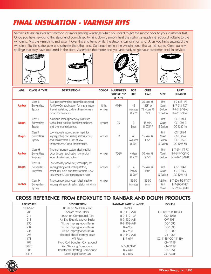
©Essex Group, Inc., 199842
FINAL INSULATION - VARNISH KITSVarnish kits are an excellent method of impregnating windings when you need to get the motor back to your customer fast.Once you have rewound the stator and completed tying it down, simply heat the stator by applying reduced voltage to thewindings. Mix the varnish kit and pour it over the end turns while the stator is standing on end. After you have saturated thewinding, flip the stator over and saturate the other end. Continue heating the winding until the varnish cures. Clean up anyspillage that may have occurred in the bore. Assemble the motor and you are ready to get your customer back in service!
MFG. CLASS & TYPE DESCRIPTION COLOR HARDNESS POT CURE PARTSHORE "D" LIFE TIME SIZE NUMBER
@ 77ºFClass B Two part solventless epoxy kit designed 30 Min. @ Pint B-7-613-1PT
Ranbar Solventless for Flow On application for impregnation Light 91/89 45 135F° or Quart B-7-613-1QTEpoxy & sealing stators, coils and transformers. Amber Minutes 72 Hours @ Gallon B-7-613-1GAL
Good for hermetics. @ 77°F 77°F 5 Gallon B-7-613-5GAL
Class F A unique semi-rigid epoxy. Fast cure Pint CC-1089-1Dolph Solventless with a long pot life. Excellent moisture. Amber 70 3 15 Min. Quart CC-1089-2
Epoxy and chemical resistance. Days @ 275° F 5 Gallon CC-1089-16
Class F Low viscosity epoxy, semi- rigid, for Pint CC-1095-1Dolph Solventless impregnating and sealing stators, coils, Amber 70 45 15 Min. @ Quart CC-1095-2
Epoxy and transformers. Cures at low Minutes 135°F Gallon CC-1095-8temperatures. Good for hermetics. @ 70°F 5 Gallon CC-1095-50
Class H Two component system designed for Pint B-7-614-1PT-FCRanbar Solventless pour through application on random Amber 70/30 4 days 30 Min. @ Quart B-7-614-1QT-FC
Polyester wound stators and rotors. @ 77°F 275°F Gallon B-7-614-1GAL-FC
Class H Low viscosity polyester, semi-rigid, for Dolph Solventless impregnating and sealing stators, Amber 78 4 15 Min. @ Pint CC-1094-1
Polyester armatures, coils and transformers. Low Hours 150°F Quart CC-1094-2cost system. Low temperature cure. @ 70ºF 5 Gallon CC-1094-45
Class H Two component system designed for Amber 35-50 35-50 1/2 Pint B-7-206-1/2-PT-KITRanbar Solventless impregnating and sealing stator windings Minutes Min. Pint B-7-206-PT-KIT
Epoxy Quart B-7-206-QT-KIT
CROSS REFERENCE FROM EPOXYLITE TO RANBAR AND DOLPH PRODUCTSEPOXYLITE DESCRIPTION RANBAR PART NUMBER DOLPH 113-67-1 Brush on Mold Release B-213
203 Sealer Paste, Black B-9-110-A/B CB-1057/CR-1034H211 Brush on Compound, Tan B-9-110-1LV CO-1060213 Air Dry Electric Motor Sealer B-9-136-A/B CW-1081230 Trickle Impregnation Resin B-9-102-A/B CC-1095234 Trickle Impregnation Resin B-7-206 CC-1095236 Trickle Impregnation Resin B-7-206 CC-1089293 Thermal Shock Potting Resin B-9-140-A/B CB-1054478 VPI Resin B-7-619 CC-1115/ CC-1118LV707 Field Coil Bonding Compound CN-11198020 Wet Winding Compound B-7-300WW CN-1119805 Transformer Potting Compound B-7-646 CB-10548117 Semi Rigid Butter On B-7-610 CR-1034H
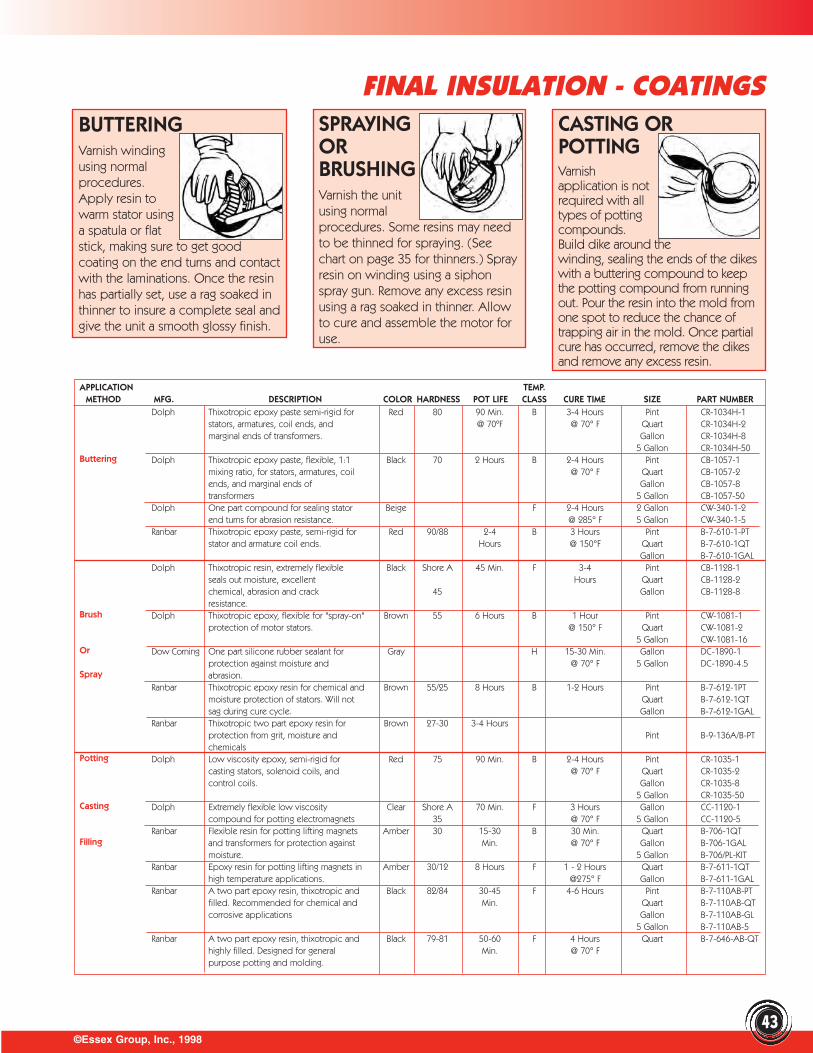
SPRAYING OR BRUSHINGVarnish the unit using normal procedures. Some resins may needto be thinned for spraying. (Seechart on page 35 for thinners.) Sprayresin on winding using a siphonspray gun. Remove any excess resinusing a rag soaked in thinner. Allowto cure and assemble the motor foruse.
BUTTERINGVarnish winding using normal procedures. Apply resin to warm stator using a spatula or flat stick, making sure to get goodcoating on the end turns and contactwith the laminations. Once the resinhas partially set, use a rag soaked inthinner to insure a complete seal andgive the unit a smooth glossy finish.
CASTING ORPOTTINGVarnish application is not required with all types of potting compounds. Build dike around the winding, sealing the ends of the dikeswith a buttering compound to keepthe potting compound from runningout. Pour the resin into the mold fromone spot to reduce the chance oftrapping air in the mold. Once partialcure has occurred, remove the dikesand remove any excess resin.
©Essex Group, Inc., 199843
FINAL INSULATION - COATINGS
APPLICATION TEMP.METHOD MFG. DESCRIPTION COLOR HARDNESS POT LIFE CLASS CURE TIME SIZE PART NUMBER
Dolph Thixotropic epoxy paste semi-rigid for Red 80 90 Min. B 3-4 Hours Pint CR-1034H-1stators, armatures, coil ends, and @ 70ºF @ 70° F Quart CR-1034H-2marginal ends of transformers. Gallon CR-1034H-8
5 Gallon CR-1034H-50Buttering Dolph Thixotropic epoxy paste, flexible, 1:1 Black 70 2 Hours B 2-4 Hours Pint CB-1057-1
mixing ratio, for stators, armatures, coil @ 70° F Quart CB-1057-2ends, and marginal ends of Gallon CB-1057-8transformers 5 Gallon CB-1057-50
Dolph One part compound for sealing stator Beige F 2-4 Hours 2 Gallon CW-340-1-2end turns for abrasion resistance. @ 285° F 5 Gallon CW-340-1-5
Ranbar Thixotropic epoxy paste, semi-rigid for Red 90/88 2-4 B 3 Hours Pint B-7-610-1-PTstator and armature coil ends. Hours @ 150°F Quart B-7-610-1QT
Gallon B-7-610-1GALDolph Thixotropic resin, extremely flexible Black Shore A 45 Min. F 3-4 Pint CB-1128-1
seals out moisture, excellent Hours Quart CB-1128-2chemical, abrasion and crack 45 Gallon CB-1128-8resistance.
Brush Dolph Thixotropic epoxy, flexible for "spray-on" Brown 55 6 Hours B 1 Hour Pint CW-1081-1protection of motor stators. @ 150° F Quart CW-1081-2
5 Gallon CW-1081-16Or Dow Corning One part silicone rubber sealant for Gray H 15-30 Min. Gallon DC-1890-1
protection against moisture and @ 70° F 5 Gallon DC-1890-4.5Spray abrasion.
Ranbar Thixotropic epoxy resin for chemical and Brown 55/25 8 Hours B 1-2 Hours Pint B-7-612-1PTmoisture protection of stators. Will not Quart B-7-612-1QTsag during cure cycle. Gallon B-7-612-1GAL
Ranbar Thixotropic two part epoxy resin for Brown 27-30 3-4 Hoursprotection from grit, moisture and Pint B-9-136A/B-PTchemicals
Potting Dolph Low viscosity epoxy, semi-rigid for Red 75 90 Min. B 2-4 Hours Pint CR-1035-1casting stators, solenoid coils, and @ 70° F Quart CR-1035-2control coils. Gallon CR-1035-8
5 Gallon CR-1035-50Casting Dolph Extremely flexible low viscosity Clear Shore A 70 Min. F 3 Hours Gallon CC-1120-1
compound for potting electromagnets 35 @ 70° F 5 Gallon CC-1120-5Ranbar Flexible resin for potting lifting magnets Amber 30 15-30 B 30 Min. Quart B-706-1QT
Filling and transformers for protection against Min. @ 70° F Gallon B-706-1GALmoisture. 5 Gallon B-706/PL-KIT
Ranbar Epoxy resin for potting lifting magnets in Amber 30/12 8 Hours F 1 - 2 Hours Quart B-7-611-1QThigh temperature applications. @275° F Gallon B-7-611-1GAL
Ranbar A two part epoxy resin, thixotropic and Black 82/84 30-45 F 4-6 Hours Pint B-7-110AB-PTfilled. Recommended for chemical and Min. Quart B-7-110AB-QTcorrosive applications Gallon B-7-110AB-GL
5 Gallon B-7-110AB-5Ranbar A two part epoxy resin, thixotropic and Black 79-81 50-60 F 4 Hours Quart B-7-646-AB-QT
highly filled. Designed for general Min. @ 70° Fpurpose potting and molding.

©Essex Group, Inc., 1998
FINAL INSULATION - PAINTS
44
AC-41 CLEARPOLYURETHANE VARNISHCLASS F (160ºC)A unique hightemperature insulatorthat dries in 30 min. to atough, clear, chemical resistant film.Can be applied by brush, dip or spray.Oil and moisture resistant, excellent forcoating circuit boards. Exhibits superiorabrasion resistance and adhesion. Thinwith T-200X. Use for coating field coils,commutator ends, electricalconnections, stators, etc.
SEMI CONDUCTIVE PAINTSWhen working on motors and generators that operate above 5KV, it is a goodpractice to bleed off the corona discharge that is created around the coils. Theprimary areas of concern are in the slot where small gaps can occur between thecoils and the iron, and where the coils exit the iron. One method is to paint thecoils with a semi conductive paint to bleed off the discharge.
VANGUARDINSULATORCLASS F (155ºC)This insulating enamel resists oil,water, acids and alkalis.Adheres well to all metalsurfaces curing to a smoothglossy finish. The film is tough, flexible,arc and track resistant. Dries to thetouch in 15 minutes. Dielectric strengthis 2000 volts/mil when dry. Available inred or black.
POLYURETHANEINSULATOR CLASS F (155ºC)A unique electricalinsulator that driesquickly to a smoothsemi-gloss finish. This air dry enameloffers excellent hiding power forrebuilding and manufacturingapplications. Exhibits excellent oil andmoisture resistance and extraordinaryabrasion resistance. Adheres well tomost surfaces. Dries to the touch in 10minutes and completely dries in 30minutes. 2000 volts/mil dielectric. 20 oz. spray cans.
DOLPH SPRAYVARNISHCLASS A (105ºC)This varnish is speciallyformulated to haveoutstanding resistance tomoisture and fungus. Good flexibilitywhen cured. Dries to the touch in 30minutes tack free in 3-1/2 hours. Clear.Conforms to MIL-V-173C-2. Dielectricstrength 2000 volts/mil.
LIMITRAK ARC &TRACK RESISTANTCOATING
A red surface coating that providessuperior insulating qualities andoutstanding track resistance. Exhibitsoutstanding chemical and moistureresistance. Two part system that whenmixed can be applied with a brush orthinned for spraying. Dielectricstrength is approx. 650 volt/mil in 20mil thickness. Cure time is approx. 3-4hours when applied, complete cure in5 days.
GLYPTAL REDINSULATOR (135ºC)This enamel exhibits unsurpassedresistance to corrosion, moisture, oil,acid, heat, dust and salt spray. Itsoutstanding adhesion allows it to stickto most any surface. Meets mil specMIL-E-22118. 1500 volt/mil dielectricstrength. Dries tack free inapproximately 30 minutes.
CLEAR INSULATINGLACQUER CLASS A(105ºC)A rapid air drying filmthat dries to a tough,flexible film. Exhibitsgood corona resistance and goodmoisture and chemical resistance.Conforms to MIL-I-17384A. Dries in 15minutes. Dielectric strength 1500volts/mil.
LAMINATION AND METAL COATERThis spray prevents rust and corrosionon all metal surfaces. Low buildassures no problems with air gaps.Light orange tint verifies coverage.Dries to the touch in 10 minutes.Dielectric strength is 2000 volts/mil.
SIZE PART NUMBER1 Gallon AC-41-15 Gallon AC-41-555 Gallon AC-41-55
SIZE PART NUMBER20 oz. Spray GLP-1201-A-SPRAY
1 Quart GLP-1201-1QT1 Gallon GLP-1201-1GAL5 Gallon GLP-1201-5GAL
SIZE PART NUMBER20 oz. Spray DS-AC-46-AF
SIZE PART NUMBER20 oz. Spray DS-LC-705
INSULATING PAINTS
COLOR SIZE PART NUMBERRED 20 oz. Spray VSP-E-208RED 1 Gallon VSP-E-208-1RED 5 Gallon VSP-E-208-5RED 55 Gallon VSP-E-208-55
BLACK 20 oz. Spray VSP-E-207
SIZE PART NUMBER20 oz. Spray DS-LAM-COAT
COLOR PART NUMBERRED DS-ER41-RED
BLACK DS-EB41-BLKRED DS-ER44-RED
SIZE PART NUMBERQuart Kit B-6-640-QT-KITGallon Kit B-6-640-1GAL-KIT
RESISTIVITYBRAND COLOR OHMS / SQ. SIZE PART NUMBERRANBAR BLACK 2000-7500 QUART B-2-135-1QTRANBAR BLACK 2000-7500 GALLON B-2-135-1GALGLYPTAL DK GREEN 2000-20,000 GALLON GLP-9921-1GAL
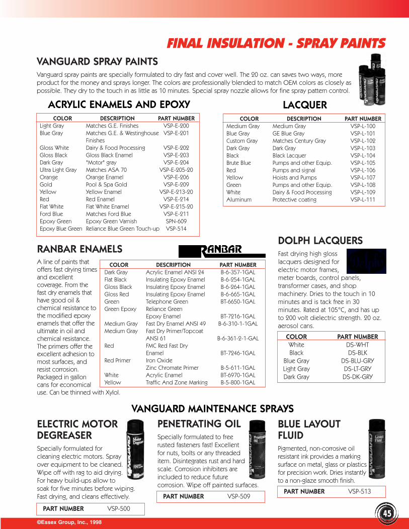
©Essex Group, Inc., 1998
FINAL INSULATION - SPRAY PAINTS
45
VANGUARD SPRAY PAINTSVanguard spray paints are specially formulated to dry fast and cover well. The 20 oz. can saves two ways, moreproduct for the money and sprays longer. The colors are professionally blended to match OEM colors as closely aspossible. They dry to the touch in as little as 10 minutes. Special spray nozzle allows for fine spray pattern control.
ACRYLIC ENAMELS AND EPOXY LACQUERCOLOR DESCRIPTION PART NUMBER
Light Gray Matches G.E. Finishes VSP-E-200Blue Gray Matches G.E. & Westinghouse VSP-E-201
FinishesGloss White Dairy & Food Processing VSP-E-202Gloss Black Gloss Black Enamel VSP-E-203Dark Gray "Motor" gray VSP-E-204Ultra Light Gray Matches ASA 70 VSP-E-205-20Orange Orange Enamel VSP-E-206Gold Pool & Spa Gold VSP-E-209Yellow Yellow Enamel VSP-E-213-20Red Red Enamel VSP-E-214Flat White Flat White Enamel VSP-E-215-20Ford Blue Matches Ford Blue VSP-E-211Epoxy Green Epoxy Green Varnish SPN-609Epoxy Blue Green Reliance Blue Green Touch-up VSP-514
COLOR DESCRIPTION PART NUMBERMedium Gray Medium Gray VSP-L-100Blue Gray GE Blue Gray VSP-L-101Custom Gray Matches Century Gray VSP-L-102Dark Gray Dark Gray VSP-L-103Black Black Lacquer VSP-L-104Brute Blue Pumps and other Equip. VSP-L-105Red Pumps and signal VSP-L-106Yellow Hoists and Pumps VSP-L-107Green Pumps and other Equip. VSP-L-108White Dairy & Food Processing VSP-L-109Aluminum Protective coating VSP-L-111
RANBAR ENAMELSA line of paints thatoffers fast drying timesand excellentcoverage. From thefast dry enamels thathave good oil &chemical resistance tothe modified epoxyenamels that offer theultimate in oil andchemical resistance.The primers offer theexcellent adhesion tomost surfaces, andresist corrosion.Packaged in galloncans for economicaluse. Can be thinned with Xylol.
COLOR DESCRIPTION PART NUMBERDark Gray Acrylic Enamel ANSI 24 B-6-357-1GALFlat Black Insulating Epoxy Enamel B-6-254-1GALGloss Black Insulating Epoxy Enamel B-6-264-1GALGloss Red Insulating Epoxy Enamel B-6-665-1GALGreen Telephone Green BT-6650-1GALGreen Epoxy Reliance Green
Epoxy Enamel BT-7216-1GALMedium Gray Fast Dry Enamel ANSI 49 B-6-310-1-1GALMedium Gray Fast Dry Primer/Topcoat
ANSI 61 B-6-361-2-1-GALRed FMC Red Fast Dry
Enamel BT-7246-1GALRed Primer Iron Oxide
Zinc Chromate Primer B-5-611-1GALWhite Acrylic Enamel BT-6970-1GALYellow Traffic And Zone Marking B-5-800-1GAL
DOLPH LACQUERSFast drying high glosslacquers designed forelectric motor frames,meter boards, control panels,transformer cases, and shopmachinery. Dries to the touch in 10minutes and is tack free in 30minutes. Rated at 105°C, and has upto 200 volt dielectric strength. 20 oz.aerosol cans.
ELECTRIC MOTORDEGREASERSpecially formulated forcleaning electric motors. Sprayover equipment to be cleaned.Wipe off with rag to aid drying.For heavy build-ups allow tosoak for five minutes before wiping.Fast drying, and cleans effectively.
PENETRATING OILSpecially formulated to freerusted fasteners fast! Excellentfor nuts, bolts or any threadeditem. Disintegrates rust and hardscale. Corrosion inhibiters areincluded to reduce futurecorrosion. Wipe off painted surfaces.
BLUE LAYOUTFLUIDPigmented, non-corrosive oilresistant ink provides a markingsurface on metal, glass or plasticsfor precision work. Dries instantlyto a non-glaze smooth finish.
PART NUMBER VSP-500
PART NUMBER VSP-509PART NUMBER VSP-513
COLOR PART NUMBERWhite DS-WHTBlack DS-BLK
Blue Gray DS-BLU-GRYLight Gray DS-LT-GRYDark Gray DS-DK-GRY
VANGUARD MAINTENANCE SPRAYS

©Essex Group, Inc., 199846
FINAL INSULATION - KRYLON SPRAY PAINT
GENERAL PURPOSE COLORS IMPLEMENT COLORSCOLOR PART NUMBER COLOR PART NUMBER
Clear Topcoat KSP-1000 International Harvester Red KSP-1003Bright Red KSP-1005 Allis Chalmers Orange KSP-1006Cherry Red KSP-1101 Ford Blue KSP-1008Joy Orange KSP-1213 Federal Highway Yellow KSP-1009Cordova Brown KSP-1285 Caterpillar Yellow (New) KSP-1318Light Beige KSP-1305 Caterpillar Yellow (Old) KSP-1320Machine Green KSP-1415 John Deere Green KSP-1485Medium Green KSP-1445 OSHA Red KSP-1110Dark Blue KSP-1515 OSHA Equipment Orange KSP-1210Light Blue KSP-1540 OSHA Yellow KSP-1310Flat White KSP-3720 OSHA Safety Green KSP-1470Semi-Flat Black KSP-3725 OSHA Blue KSP-1510Max Flat Black KSP-3727 OSHA Purple KSP-1580
OSHA Black KSP-1770OSHA White KSP-1800
METALLICS PRIMERSCOLOR PART NUMBER COLOR PART NUMBER
Aluminum KSP-1760 Red Oxide RustGold KSP-1765 Control Primer KSP-342
Gray Rust Control Primer KSP-340
KRYLON TOUGH COAT PAINTSThese flexible industrial acrylic enamels are ideal for lightto heavy duty painting projects, both indoor and outdoor.The tough protective coating resists chipping and peeling.
• Excellent hiding characteristics• Smooth even coverage• Fast drying-15 minutes to the touch
equipped with the EZ touch Fanspray nozzle
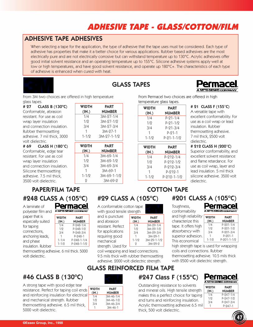
©Essex Group, Inc., 1998
ADHESIVE TAPE - GLASS/COTTON/FILMADHESIVE TAPE ADHESIVES
When selecting a tape for the application, the type of adhesive that the tape uses must be considered. Each type ofadhesive has properties that make it a better choice for various applications. Rubber based adhesives are the mostelectrically pure and are not electrically corrosive but can withstand temperature up to 130°C. Acrylic adhesives offergood initial solvent resistance and an operating temperature up to 155°C. Silicone adhesive systems apply well atlow or high temperatures, and have good solvent resistance, and operate up 180°C+. The characteristics of each typeof adhesive is enhanced when cured with heat.
From Permacel two choices are offered in hightemperature glass tapes.
# 21 CLASS F (155°C)A versatile tape withexcellent conformability. Foruse as a coil wrap or leadinsulation. Rubber thermosetting adhesive. 7 mil thick, 2500 voltdielectric.# 212 CLASS H (200°C)Superior conformability, andexcellent solvent resistanceand flame retardance. Foruse as coil wrap, layer andlead insulation. 5 mil thicksilicone adhesive. 3500 voltdielectric.
PAPER/FILM TAPE#248 CLASS A (105ºC)A laminate ofpolyester film andpaper that isespecially suitedfor tapingconnections,anchoring leads,and phaseinsulation. Rubberthermosetting adhesive. 6 mil thick. 5000volt dielectric.
WIDTH PART (IN.) NUMBER1/4 P-248-1/41/2 P-248-1/23/4 P-248-3/41 P-248-1
1-1/4 P-248-1-1/41-1/2 P-248-1-1/2
COTTON TAPE#29 CLASS A (105ºC)A conformable cotton tapewith good tensile strengthand is punctureand abrasionresistant. Perfectfor applicationsrequiring goodmechanicalstrength. Used forcoil wrapping and lead connections.9.5 mils thick with rubber thermosettingadhesive. 2000 volt dielectric strength.
#201 CLASS A (105ºC)Toughness,conformabilityand high reliabilitycharacterize thistape. It offers highabsorbency withsuperior adhesion.This economicalhigh strength tape is used for wrappingcoils and connections. Rubberthermosetting adhesive. 10.5 mils thickwith 2500 volt dielectric strength.
#46 CLASS B (130ºC)A strong tape with good edge tearresistance. Perfect for taping coil endsand reinforcing insulation for electricaland mechanical strength. Rubberthermosetting adhesive. 6.5 mil thick,5000 volt dielectric.
#247 Class F (155ºC)Outstanding resistance to solventsand mineral oils. High tensile strengthmakes this a perfect choice for taping end turns and reinforcing insulation.Acrylic thermosetting adhesive 6.5 milthick, 500 volt dielectric.
From 3M two choices are offered in high temperatureglass tapes.# 27 CLASS B (130ºC) Conformable, abrasionresistant. For use as coilwrap layer insulation and connection insulation.Rubber thermosetting adhesive. 7 mil thick, 3000volt dielectric.# 69 CLASS H (180°C)Conformable, edge tearresistant. For use as coilwrap layer insulation and connection insulation.Silicone thermosettingadhesive. 7.5 mil thick,3500 volt dielectric.
WIDTH PART(IN.) NUMBER1/4 3M-27-1/41/2 3M-27-1/23/4 3M-27-3/41 3M-27-1
1-1/2 3M-27-1-1/2
WIDTH PART(IN.) NUMBER1/4 3M-69-1/41/2 3M-69-1/23/4 3M-69-3/41 3M-69-1
1-1/2 3M-69-1-1/22 3M-69-2
WIDTH PART(IN.) NUMBER1/4 P-21-1/41/2 P-21-1/23/4 P-21-3/41 P-21-1
1-1/2 P-21-1-1/2
WIDTH PART(IN.) NUMBER1/4 P-212-1/41/2 P-212-1/23/4 P-212-3/41 P-212-1
1-1/2 P-212-1-1/2
GLASS TAPES
WIDTH PART (IN.) NUMBER1/4 3M-29-1/41/2 3M-29-1/23/4 3M-29-3/41 3M-29-1
1-1/2 3M-29-1-1/22 3M-29-2
WIDTH PART (IN.) NUMBER1/4 P-201-1/41/2 P-201-1/23/4 P-201-3/41 P-201-1
1-1/2 P-201-1-1/2
GLASS REINFORCED FILM TAPE
WIDTH PART (IN.) NUMBER1/4 3M-46-1/41/2 3M-46-1/23/4 3M-46-3/41 3M-46-1
WIDTH PART (IN.) NUMBER1/4 P-247-1/41/2 P-247-1/23/4 P-247-3/41 P-247-1
47
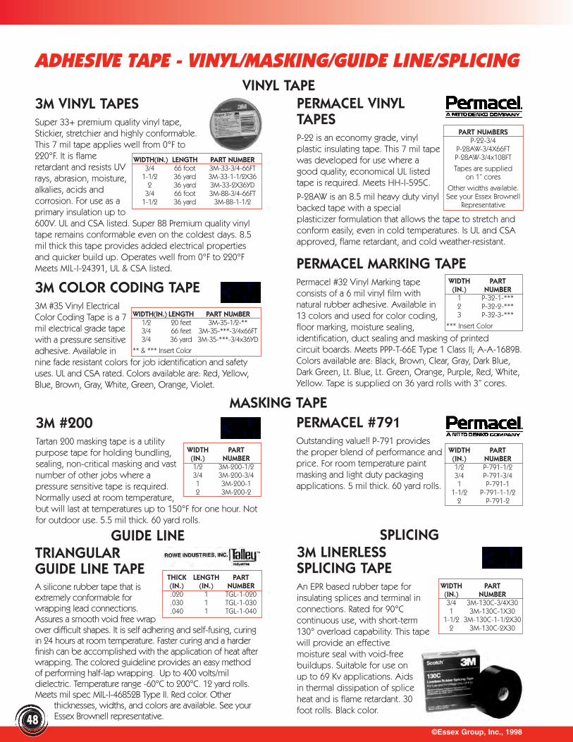
©Essex Group, Inc., 1998
ADHESIVE TAPE - VINYL/MASKING/GUIDE LINE/SPLICING
3M VINYL TAPESSuper 33+ premium quality vinyl tape,Stickier, stretchier and highly conformable.This 7 mil tape applies well from 0°F to220°F. It is flameretardant and resists UVrays, abrasion, moisture,alkalies, acids andcorrosion. For use as aprimary insulation up to600V. UL and CSA listed. Super 88 Premium quality vinyltape remains conformable even on the coldest days. 8.5mil thick this tape provides added electrical propertiesand quicker build up. Operates well from 0°F to 220°FMeets MIL-I-24391, UL & CSA listed.
PERMACEL VINYLTAPESP-22 is an economy grade, vinylplastic insulating tape. This 7 mil tapewas developed for use where agood quality, economical UL listedtape is required. Meets HH-I-595C.
P-28AW is an 8.5 mil heavy duty vinylbacked tape with a specialplasticizer formulation that allows the tape to stretch andconform easily, even in cold temperatures. Is UL and CSAapproved, flame retardant, and cold weather-resistant.
PART NUMBERSP-22-3/4
P-28AW-3/4X66FTP-28AW-3/4x108FT
Tapes are suppliedon 1” cores
Other widths available. See your Essex Brownell
Representative
3M #200Tartan 200 masking tape is a utilitypurpose tape for holding bundling,sealing, non-critical masking and vastnumber of other jobs where apressure sensitive tape is required.Normally used at room temperature,but will last at temperatures up to 150°F for one hour. Notfor outdoor use. 5.5 mil thick. 60 yard rolls.
PERMACEL #791Outstanding value!! P-791 providesthe proper blend of performance andprice. For room temperature paintmasking and light duty packagingapplications. 5 mil thick. 60 yard rolls.
GUIDE LINETRIANGULARGUIDE LINE TAPEA silicone rubber tape that isextremely conformable forwrapping lead connections.Assures a smooth void free wrapover difficult shapes. It is self adhering and self-fusing, curingin 24 hours at room temperature. Faster curing and a harderfinish can be accomplished with the application of heat afterwrapping. The colored guideline provides an easy methodof performing half-lap wrapping. Up to 400 volts/mildielectric. Temperature range -60°C to 200°C. 12 yard rolls.Meets mil spec MIL-I-46852B Type II. Red color. Other
thicknesses, widths, and colors are available. See your Essex Brownell representative.
SPLICING3M LINERLESS SPLICING TAPEAn EPR based rubber tape forinsulating splices and terminal inconnections. Rated for 90°Ccontinuous use, with short-term130° overload capability. This tapewill provide an effectivemoisture seal with void-freebuildups. Suitable for use onup to 69 Kv applications. Aidsin thermal dissipation of spliceheat and is flame retardant. 30foot rolls. Black color.
3M COLOR CODING TAPE3M #35 Vinyl ElectricalColor Coding Tape is a 7mil electrical grade tapewith a pressure sensitiveadhesive. Available innine fade resistant colors for job identification and safetyuses. UL and CSA rated. Colors available are: Red, Yellow,Blue, Brown, Gray, White, Green, Orange, Violet.
PERMACEL MARKING TAPEPermacel #32 Vinyl Marking tapeconsists of a 6 mil vinyl film withnatural rubber adhesive. Available in13 colors and used for color coding,floor marking, moisture sealing,identification, duct sealing and masking of printed circuit boards. Meets PPP-T-66E Type 1 Class II; A-A-1689B.Colors available are: Black, Brown, Clear, Gray, Dark Blue,Dark Green, Lt. Blue, Lt. Green, Orange, Purple, Red, White,Yellow. Tape is supplied on 36 yard rolls with 3” cores.
VINYL TAPE
WIDTH(IN.) LENGTH PART NUMBER3/4 66 foot 3M-33-3/4-66FT
1-1/2 36 yard 3M-33-1-1/2X362 36 yard 3M-33-2X36YD
3/4 66 foot 3M-88-3/4-66FT1-1/2 36 yard 3M-88-1-1/2
WIDTH PART(IN.) NUMBER
1 P-32-1-***2 P-32-2-***3 P-32-3-***
*** Insert Color
WIDTH(IN.) LENGTH PART NUMBER1/2 20 feet 3M-35-1/2-**3/4 66 feet 3M-35-***-3/4x66FT3/4 36 yard 3M-35-***-3/4x36YD
** & *** Insert Color
MASKING TAPE
WIDTH PART(IN.) NUMBER1/2 P-791-1/23/4 P-791-3/41 P-791-1
1-1/2 P-791-1-1/22 P-791-2
WIDTH PART(IN.) NUMBER1/2 3M-200-1/23/4 3M-200-3/41 3M-200-12 3M-200-2
THICK LENGTH PART(IN.) (IN.) NUMBER.020 1 TGL-1-020.030 1 TGL-1-030.040 1 TGL-1-040
48
WIDTH PART(IN.) NUMBER3/4 3M-130C-3/4X301 3M-130C-1X30
1-1/2 3M-130C-1-1/2X302 3M-130C-2X30
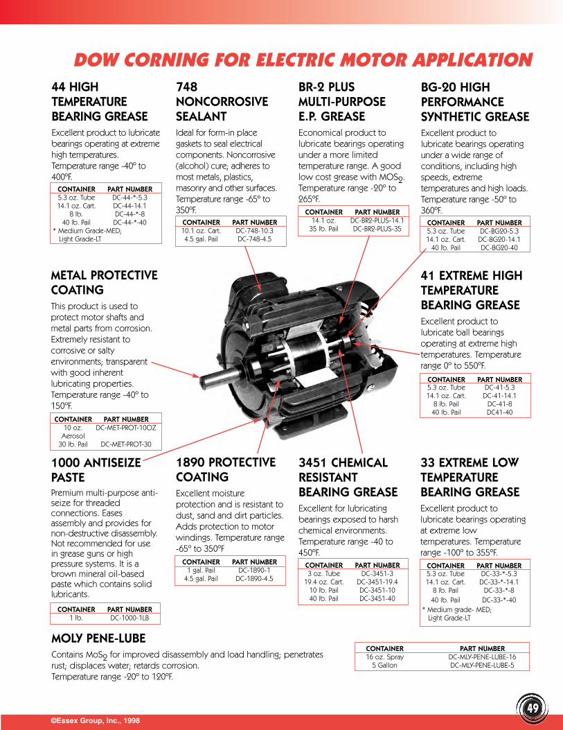
©Essex Group, Inc., 199849
DOW CORNING FOR ELECTRIC MOTOR APPLICATION
METAL PROTECTIVECOATINGThis product is used toprotect motor shafts andmetal parts from corrosion.Extremely resistant tocorrosive or saltyenvironments; transparentwith good inherentlubricating properties.Temperature range -40º to150ºF.
1000 ANTISEIZEPASTEPremium multi-purpose anti-seize for threadedconnections. Easesassembly and provides fornon-destructive disassembly.Not recommended for usein grease guns or highpressure systems. It is abrown mineral oil-basedpaste which contains solidlubricants.
1890 PROTECTIVECOATINGExcellent moistureprotection and is resistant todust, sand and dirt particles.Adds protection to motorwindings. Temperature range-65º to 350ºF
3451 CHEMICALRESISTANTBEARING GREASEExcellent for lubricatingbearings exposed to harshchemical environments.Temperature range -40 to450ºF.
748NONCORROSIVESEALANTIdeal for form-in placegaskets to seal electricalcomponents. Noncorrosive(alcohol) cure; adheres tomost metals, plastics,masonry and other surfaces.Temperature range -65º to350ºF.
BR-2 PLUS MULTI-PURPOSE E.P. GREASEEconomical product tolubricate bearings operatingunder a more limitedtemperature range. A goodlow cost grease with MOS2.Temperature range -20º to265ºF.
BG-20 HIGHPERFORMANCESYNTHETIC GREASEExcellent product tolubricate bearings operatingunder a wide range ofconditions, including highspeeds, extremetemperatures and high loads.Temperature range -50º to360ºF.
41 EXTREME HIGHTEMPERATUREBEARING GREASEExcellent product tolubricate ball bearingsoperating at extreme hightemperatures. Temperaturerange 0º to 550ºF.
33 EXTREME LOWTEMPERATUREBEARING GREASEExcellent product tolubricate bearings operatingat extreme lowtemperatures. Temperaturerange -100º to 355ºF.
MOLY PENE-LUBEContains MoS2 for improved disassembly and load handling; penetrates rust; displaces water; retards corrosion. Temperature range -20º to 120ºF.
44 HIGHTEMPERATUREBEARING GREASEExcellent product to lubricatebearings operating at extremehigh temperatures.Temperature range -40º to400ºF.
CONTAINER PART NUMBER5.3 oz. Tube DC-44-*-5.3 14.1 oz. Cart. DC-44-14.1
8 lb. DC-44-*-840 lb. Pail DC-44-*-40
* Medium Grade-MED; Light Grade-LT
CONTAINER PART NUMBER10.1 oz. Cart. DC-748-10.34.5 gal. Pail DC-748-4.5
CONTAINER PART NUMBER14.1 oz. DC-BR2-PLUS-14.1
35 lb. Pail DC-BR2-PLUS-35CONTAINER PART NUMBER5.3 oz. Tube DC-BG20-5.3 14.1 oz. Cart. DC-BG20-14.1
40 lb. Pail DC-BG20-40
CONTAINER PART NUMBER5.3 oz. Tube DC-41-5.314.1 oz. Cart. DC-41-14.1
8 lb. Pail DC-41-840 lb. Pail DC41-40
CONTAINER PART NUMBER5.3 oz. Tube DC-33-*-5.3 14.1 oz. Cart. DC-33-*-14.1
8 lb. Pail DC-33-*-840 lb. Pail DC-33-*-40
* Medium grade- MED;Light Grade-LT
CONTAINER PART NUMBER3 oz. Tube DC-3451-3
19.4 oz. Cart. DC-3451-19.4 10 lb. Pail DC-3451-10 40 lb. Pail DC-3451-40
CONTAINER PART NUMBER1 gal. Pail DC-1890-1
4.5 gal. Pail DC-1890-4.5
CONTAINER PART NUMBER1 lb. DC-1000-1LB
CONTAINER PART NUMBER16 oz. Spray DC-MLY-PENE-LUBE-16
5 Gallon DC-MLY-PENE-LUBE-5
CONTAINER PART NUMBER10 oz. DC-MET-PROT-10OZ
Aerosol30 lb. Pail DC-MET-PROT-30
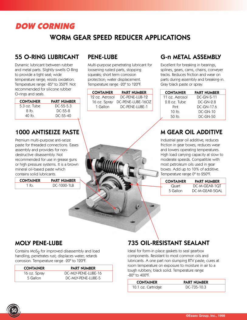
©Essex Group, Inc., 199850
DOW CORNINGWORM GEAR SPEED REDUCER APPLICATIONS
55 O-RING LUBRICANTDynamic lubricant between rubberand metal parts. Slightly swells O-Ringto provide a tight seal; widetemperature range; resists oxidation.Temperature range -85º to 350ºF. Notrecommended for silicone rubberO-rings and seals.
PENE-LUBEMulti-purpose penetrating lubricant forloosening rusted parts, stoppingsqueaks; short term corrosionprotection; water displacement.Temperature range -20º to 120ºF.
G-n METAL ASSEMBLY Excellent for breaking in bearings,splines, gears, cams, chains, conveyertracks. Reduces friction and wear onparts during assembly and breaking-in.Gray black paste or spray.
M GEAR OIL ADDITIVEIndustrial gear oil additive; reducesfriction in gear boxes; reduces wearand lowers operating temperatures.High load carrying capacity at slow tomoderate speeds. Compatible withmost petroleum oils used in gearboxes. Add up to 10% of additive.Temperature range 0º to 250ºF.
MOLY PENE-LUBEContains MoS2 for improved disassembly and loadhandling; penetrates rust; displaces water; retardscorrosion. Temperature range -20º to 120ºF.
735 OIL-RESISTANT SEALANTIdeal for form-in place gaskets to seal gearboxcomponents. Resistant to most common oils andlubricants. A one part non slumping RTV paste; cures atroom temperature on exposure to moisture in air to atough rubbery, black solid. Temperature range -80º to 400ºF.
CONTAINER PART NUMBER5.3 oz. Tube DC-55-5.3
8 lb. DC-55-840 lb. DC-55-40
CONTAINER PART NUMBER12 oz. Aerosol DC-PENE-LUB-1216 oz. Spray DC-PENE-LUBE-16OZ
1 Gallon DC-PENE-LUBE-1
CONTAINER PART NUMBER11 oz. Aerosol DC-GN-S-112.8 oz. Tube DC-GN-2.8
Pint DC-GN-17.610 lb. DC-GN-1050 lb. DC-GN-50
1000 ANTISEIZE PASTEPremium multi-purpose anti-seizepaste for threaded connections. Easesassembly and provides for non-destructive disassembly. Notrecommended for use in grease gunsor high pressure systems. It is a brownmineral oil-based paste whichcontains solid lubricants.
CONTAINER PART NUMBER1 lb. DC-1000-1LB
CONTAINER PART NUMBERQuart DC-M-GEAR-1QT
5 Gallon DC-M-GEAR-5GAL
CONTAINER PART NUMBER16 oz. Spray DC-MLY-PENE-LUBE-16
5 Gallon DC-MLY-PENE-LUBE-5CONTAINER PART NUMBER
10.1 oz. Cartridge DC-735-10.3
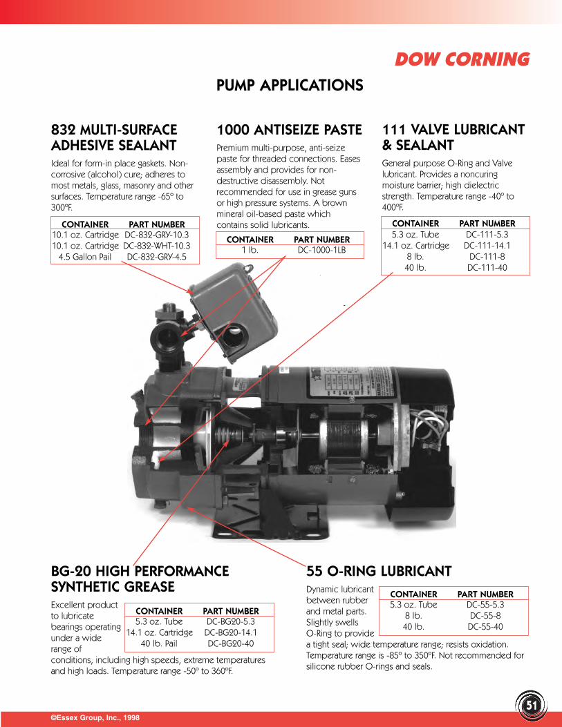
©Essex Group, Inc., 1998
DOW CORNING
51
832 MULTI-SURFACEADHESIVE SEALANTIdeal for form-in place gaskets. Non-corrosive (alcohol) cure; adheres tomost metals, glass, masonry and othersurfaces. Temperature range -65º to300ºF.
111 VALVE LUBRICANT& SEALANTGeneral purpose O-Ring and Valvelubricant. Provides a noncuringmoisture barrier; high dielectricstrength. Temperature range -40º to400ºF.
1000 ANTISEIZE PASTEPremium multi-purpose, anti-seizepaste for threaded connections. Easesassembly and provides for non-destructive disassembly. Notrecommended for use in grease gunsor high pressure systems. A brownmineral oil-based paste whichcontains solid lubricants.
55 O-RING LUBRICANTDynamic lubricantbetween rubberand metal parts.Slightly swellsO-Ring to providea tight seal; wide temperature range; resists oxidation.Temperature range is -85º to 350ºF. Not recommended forsilicone rubber O-rings and seals.
BG-20 HIGH PERFORMANCESYNTHETIC GREASEExcellent productto lubricatebearings operatingunder a widerange ofconditions, including high speeds, extreme temperaturesand high loads. Temperature range -50º to 360ºF.
PUMP APPLICATIONS
CONTAINER PART NUMBER10.1 oz. Cartridge DC-832-GRY-10.310.1 oz. Cartridge DC-832-WHT-10.3
4.5 Gallon Pail DC-832-GRY-4.5
CONTAINER PART NUMBER1 lb. DC-1000-1LB
CONTAINER PART NUMBER5.3 oz. Tube DC-111-5.3
14.1 oz. Cartridge DC-111-14.18 lb. DC-111-840 lb. DC-111-40
CONTAINER PART NUMBER5.3 oz. Tube DC-BG20-5.3
14.1 oz. Cartridge DC-BG20-14.140 lb. Pail DC-BG20-40
CONTAINER PART NUMBER5.3 oz. Tube DC-55-5.3
8 lb. DC-55-840 lb. DC-55-40
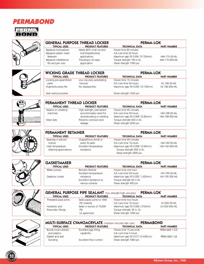
©Essex Group, Inc., 199852
PERMABOND
GENERAL PURPOSE THREAD LOCKER PERMA-LOKTYPICAL USES PRODUCT FEATURES TECHNICAL DATA PART NUMBER
Replaces lockwashers Meets 80% of all nut and Fixture time 20 minutesReplaces plastic insert bolt threadlocking Full cure time 24 hours
fasteners applications Maximum gap fill 0.006 ”(0.150mm) MM-115-50-ML Replaces interference Thixotropic for easy Torque strength 100 in-lb. MM-115-250-ML
fits and jam nuts application Shear strength 1500 psi
WICKING GRADE THREAD LOCKER PERMA-LOKTYPICAL USES PRODUCT FEATURES TECHNICAL DATA PART NUMBER
Locking pre-assembled Low viscosity penetrating Fixture time 15 minutesparts formula Full cure time 24 hours HL-126-50-ML
Augments press fits No disassembly Maximum gap fill 0.005 “(0.130mm) HL-126-250-ML
Seal weld porosities Shear strength 1500 psi
PERMANENT THREAD LOCKER PERMA-LOKTYPICAL USES PRODUCT FEATURES TECHNICAL DATA PART NUMBER
Fastens on vibrating High strength, permanent Fixture time 20 minutesmachines and eliminates need for Full cure time 24 hours HM-128-50-ML
doublenutting or welding Maximum gap fill 0.008 “(0.20mm) HM-128-250-ML Valve Sets Prevents corrosion and Torque strength 250 in-lb.
leakage Shear strength 2500 psi
PERMANENT RETAINER PERMA-LOKTYPICAL USES PRODUCT FEATURES TECHNICAL DATA PART NUMBER
Bearings in electric Outperforms shrink or Fixture time 20 minutesmotors press fit parts Full cure time 16 hours HM-160-50-ML
High temperature Excellent temperature Maximum gap fill 0.008 “(0.20mm) HM-160-250-ML retaining applications resistance Torque strength 250 in-lb.
Shear strength 3000 psi
GASKETMAKER PERMA-LOKTYPICAL USES PRODUCT FEATURES TECHNICAL DATA PART NUMBER
Water pumps Remains flexible Fixture time one hourExcellent temperature Full cure time 24 hours HH-190-50-ML
Gearbox covers resistance Maximum gap fill 0.025 “(.635mm) HH-190-300-ML Excellent resistance to Torque strength 65 in-lb.
various solvents Shear strength 900 psi
GENERAL PURPOSE PIPE SEALANT (low strength-high viscosity) PERMA-LOKTYPICAL USES PRODUCT FEATURES TECHNICAL DATA PART NUMBER
Threaded pipe joints Seals pipes joints to 1000 Fixture time two hoursPSI instantly Full cure time 16 hours LH-050-50-ML
Hydraulic and Seals in excess of 10,000 Maximum gap fill 0.020 (.510mm) LH-050-250-ML Pneumatic fittings PSI Torque strength 35 in. lb.
UL approved Shear strength 1000 psi
MULTI-SURFACE CYANOACRYLATE (medium viscosity fast cure) PERMABONDTYPICAL USES PRODUCT FEATURES TECHNICAL DATA PART NUMBER
Bonds most rubbers Excellent gap filling Fixture time 15 seconds PERM-268-1-OZand plastics capability Full cure time 4 hours
Gasket and seal Maximum gap fill 0.017 (0.430mm) PERM-268-1-LB bonding Excellent flow control Shear strength 1800 psi

©Essex Group, Inc., 1998
PERMABOND
53
METAL BONDING CYANOACRYLATE PERMABONDTYPICAL USES PRODUCT FEATURES TECHNICAL DATA PART NUMBER
Metal to metal Excellent for bonding- Fixture time 15 seconds PERM-910-3-GRand rubber metal to metal Full cure time 4 hours
Maximum gap fill 0.005 (0.130mm) PERM-910-1-OZ Low viscosity PERM-910-1-LB
Shear strength 3000 psi
NON-DRIP CYANOACRYLATE PERMABONDTYPICAL USES PRODUCT FEATURES TECHNICAL DATA PART NUMBER
For use on vertical Non-drip rheology formula Fixture time 30 secondsapplications Excellent for use on Full cure time 4 hours
For bonding most metals porous surfaces Maximum gap fill 0.025 (0.130mm) PERM-2010-1-OZ plastics and rubber PERM-2010-1-LB
Shear strength 2000 psi
RAPID EPOXY REPAIR (FAST CURE) PERMABONDTYPICAL USES PRODUCT FEATURES TECHNICAL DATA PART NUMBER
For rapid repair of Rapid cure rate Fixture time 5 minutes PERM-E01-50MLmaintenance items such Full cure time 1 hoursas metals, plastics, glass Easily dispensed Maximum gap fill 0.20 (5.1mm)and other porous Excellent gap fillingceramics capabilities Shear strength 700 psi
TOUGHENED EPOXY (STRUCTURAL BONDING) PERMABONDTYPICAL USES PRODUCT FEATURES TECHNICAL DATA PART NUMBER
For use in general Rapid cure rate Fixture time 2 hour PERM-E04-50MLstructural bonding of Full cure time 24 hoursmetals and plastics Excellent gap filling Maximum gap fill 0.20 (5.1mm)
capabilities Shear strength 3000 psi
FE RAPID (EMERGENCY METAL REPAIR) PERMABONDTYPICAL USES PRODUCT FEATURES TECHNICAL DATA PART NUMBER
Seals cracks in metals Fast cure time reduces Fixture time 3 hours PERM-FE-RAP-400MLdown time Full cure time 6 hours
Internal bores of pipes Excellent gap filling Maximum gap fill 0.20 valves and fittings capabilities (5.1mm)
TOUGHEN ACRYLIC (FAST CURE) PERMABONDTYPICAL USES PRODUCT FEATURES TECHNICAL DATA PART NUMBER
Provides strong bond Excellent resistance to Fixture time 2 minutes PERM-F246-50MLto wood, plastic,glass harsh environmentals Full cure time 4 hoursand metal No pre-cleaning of oily Maximum gap fill 0.25 (5.1mm)
metals requiredShear strength 4,000 psi
ANTI-SEIZE (METAL CORROSION PREVENTION) PERMABONDTYPICAL USES PRODUCT FEATURES TECHNICAL DATA PART NUMBER
For use on metal parts to Forms a protective film Remains flexible PERM-ANTISEIZE-1 prevent corrosion which cannot be burned
off Recommended thicknessAids in assembly by Resistant to salt water and 0.40 (10.2mm)
preventing galling other harsh environments
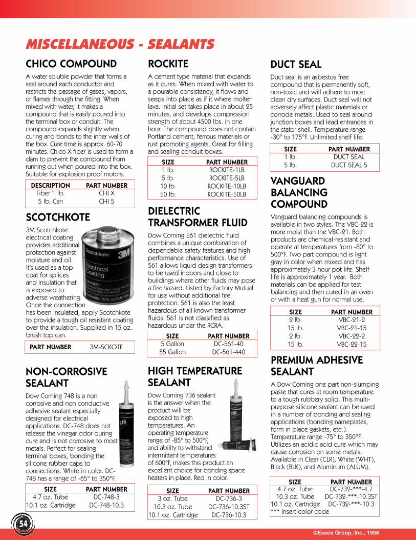
©Essex Group, Inc., 199854
MISCELLANEOUS - SEALANTSCHICO COMPOUNDA water soluble powder that forms aseal around each conductor andrestricts the passage of gases, vapors,or flames through the fitting. Whenmixed with water, it makes acompound that is easily poured intothe terminal box or conduit. Thecompound expands slightly whencuring and bonds to the inner walls ofthe box. Cure time is approx. 60-70minutes. Chico X fiber is used to form adam to prevent the compound fromrunning out when poured into the box.Suitable for explosion proof motors.
VANGUARDBALANCINGCOMPOUNDVanguard balancing compounds isavailable in two styles. The VBC-22 ismore moist than the VBC-21. Bothproducts are chemical-resistant andoperate at temperatures from -80° to500°F. Two part compound is lightgray in color when mixed and hasapproximately 3 hour pot life. Shelflife is approximately 1 year. Bothmaterials can be applied for testbalancing and then cured in an ovenor with a heat gun for normal use.
DIELECTRICTRANSFORMER FLUID Dow Corning 561 dielectric fluidcombines a unique combination ofdependable safety features and highperformance characteristics. Use of561 allows liquid design transformersto be used indoors and close tobuildings where other fluids may posea fire hazard. Listed by Factory Mutualfor use without additional fireprotection. 561 is also the leasthazardous of all known transformerfluids. 561 is not classified ashazardous under the RCRA.
PREMIUM ADHESIVESEALANTA Dow Corning one part non-slumpingpaste that cures at room temperatureto a tough rubbery solid. This multi-purpose silicone sealant can be usedin a number of bonding and sealingapplications (bonding nameplates,form in place gaskets, etc.).Temperature range -75° to 350°F.Utilizes an acidic acid cure which maycause corrosion on some metals.Available in Clear (CLR), White (WHT),Black (BLK), and Aluminum (ALUM).
HIGH TEMPERATURESEALANTDow Corning 736 sealantis the answer when theproduct will beexposed to hightemperatures. Anoperating temperaturerange of -85° to 500°F,and ability to withstandintermittent temperaturesof 600°F, makes this product anexcellent choice for bonding spaceheaters in place. Red in color.
NON-CORROSIVESEALANTDow Corning 748 is a noncorrosive and non conductiveadhesive sealant especiallydesigned for electricalapplications. DC-748 does notrelease the vinegar odor duringcure and is not corrosive to mostmetals. Perfect for sealingterminal boxes, bonding thesilicone rubber caps toconnections. White in color. DC-748 has a range of -65° to 350°F.
ROCKITEA cement type material that expandsas it cures. When mixed with water toa pourable consistency, it flows andseeps into place as if it where moltenlava. Initial set takes place in about 25minutes, and develops compressionstrength of about 4500 lbs. in onehour. The compound does not containPortland cement, ferrous materials orrust promoting agents. Great for fillingand sealing conduit boxes.
DUCT SEALDuct seal is an asbestos freecompound that is permanently soft,non-toxic and will adhere to mostclean dry surfaces. Duct seal will notadversely affect plastic materials orcorrode metals. Used to seal aroundjunction boxes and lead entrances inthe stator shell. Temperature range-30° to 175°F. Unlimited shelf life.
DESCRIPTION PART NUMBERFiber 1 lb. CHI X5 lb. Can CHI 5
SIZE PART NUMBER1 lb. ROCKITE-1LB5 lb. ROCKITE-5LB10 lb. ROCKITE-10LB50 lb. ROCKITE-50LB
SIZE PART NUMBER1 lb. DUCT SEAL5 lb. DUCT SEAL 5
PART NUMBER 3M-SCKOTE
SIZE PART NUMBER2 lb. VBC-21-215 lb. VBC-21-152 lb. VBC-22-215 lb. VBC-22-15
SIZE PART NUMBER5 Gallon DC-561-4055 Gallon DC-561-440
SIZE PART NUMBER4.7 oz. Tube DC-732-***-4.710.3 oz. Tube DC-732-***-10.3ST
10.1 oz. Cartridge DC-732-***-10.3*** Insert color code
SIZE PART NUMBER3 oz. Tube DC-736-3
10.3 oz. Tube DC-736-10.3ST10.1 oz. Cartridge DC-736-10.3
SIZE PART NUMBER4.7 oz. Tube DC-748-3
10.1 oz. Cartridge DC-748-10.3
SCOTCHKOTE3M Scotchkote electrical coating provides additional protection against moisture and oil. It’s used as a top coat for splices and insulation that is exposed to adverse weathering. Once the connection has been insulated, apply Scotchkoteto provide a tough oil resistant coatingover the insulation. Supplied in 15 oz.brush top can.
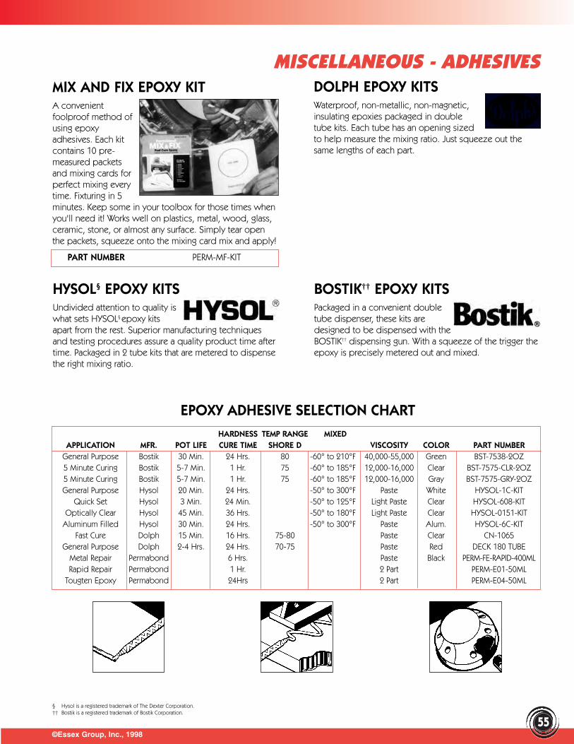
HARDNESS TEMP RANGE MIXEDAPPLICATION MFR. POT LIFE CURE TIME SHORE D VISCOSITY COLOR PART NUMBER
General Purpose Bostik 30 Min. 24 Hrs. 80 -60° to 210°F 40,000-55,000 Green BST-7538-2OZ5 Minute Curing Bostik 5-7 Min. 1 Hr. 75 -60° to 185°F 12,000-16,000 Clear BST-7575-CLR-2OZ5 Minute Curing Bostik 5-7 Min. 1 Hr. 75 -60° to 185°F 12,000-16,000 Gray BST-7575-GRY-2OZGeneral Purpose Hysol 20 Min. 24 Hrs. -50° to 300°F Paste White HYSOL-1C-KIT
Quick Set Hysol 3 Min. 24 Min. -50° to 125°F Light Paste Clear HYSOL-608-KITOptically Clear Hysol 45 Min. 36 Hrs. -50° to 180°F Light Paste Clear HYSOL-0151-KIT
Aluminum Filled Hysol 30 Min. 24 Hrs. -50° to 300°F Paste Alum. HYSOL-6C-KITFast Cure Dolph 15 Min. 16 Hrs. 75-80 Paste Clear CN-1065
General Purpose Dolph 2-4 Hrs. 24 Hrs. 70-75 Paste Red DECK 180 TUBEMetal Repair Permabond 6 Hrs. Paste Black PERM-FE-RAPID-400MLRapid Repair Permabond 1 Hr. 2 Part PERM-E01-50ML
Tougten Epoxy Permabond 24Hrs 2 Part PERM-E04-50ML
©Essex Group, Inc., 199855
MISCELLANEOUS - ADHESIVESMIX AND FIX EPOXY KITA convenientfoolproof method ofusing epoxyadhesives. Each kitcontains 10 pre-measured packetsand mixing cards forperfect mixing everytime. Fixturing in 5minutes. Keep some in your toolbox for those times whenyou'll need it! Works well on plastics, metal, wood, glass,ceramic, stone, or almost any surface. Simply tear openthe packets, squeeze onto the mixing card mix and apply!
DOLPH EPOXY KITSWaterproof, non-metallic, non-magnetic,insulating epoxies packaged in doubletube kits. Each tube has an opening sizedto help measure the mixing ratio. Just squeeze out thesame lengths of each part.
HYSOL§ EPOXY KITSUndivided attention to quality iswhat sets HYSOL§ epoxy kits apart from the rest. Superior manufacturing techniquesand testing procedures assure a quality product time aftertime. Packaged in 2 tube kits that are metered to dispensethe right mixing ratio.
BOSTIK†† EPOXY KITSPackaged in a convenient doubletube dispenser, these kits aredesigned to be dispensed with theBOSTIK†† dispensing gun. With a squeeze of the trigger theepoxy is precisely metered out and mixed.
EPOXY ADHESIVE SELECTION CHART
PART NUMBER PERM-MF-KIT
§ Hysol is a registered trademark of The Dexter Corporation.†† Bostik is a registered trademark of Bostik Corporation.
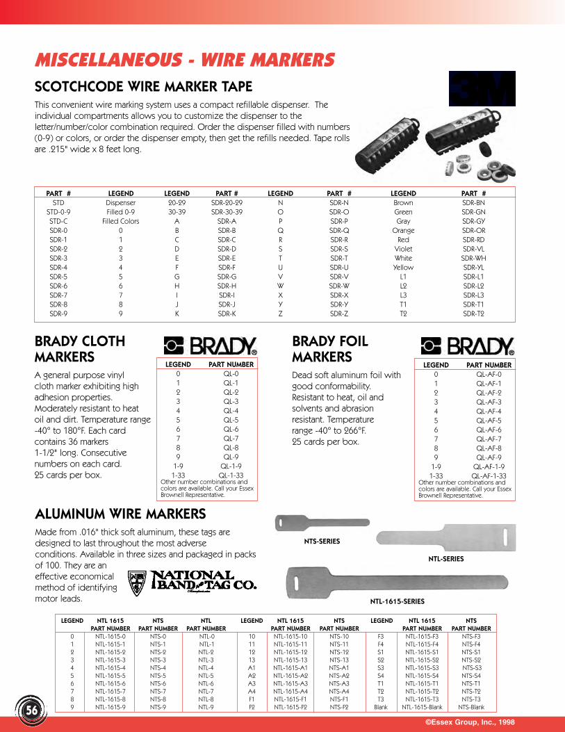
©Essex Group, Inc., 1998
MISCELLANEOUS - WIRE MARKERS
56
SCOTCHCODE WIRE MARKER TAPEThis convenient wire marking system uses a compact refillable dispenser. Theindividual compartments allows you to customize the dispenser to theletter/number/color combination required. Order the dispenser filled with numbers(0-9) or colors, or order the dispenser empty, then get the refills needed. Tape rollsare .215" wide x 8 feet long.
PART # LEGEND LEGEND PART # LEGEND PART # LEGEND PART #STD Dispenser 20-29 SDR-20-29 N SDR-N Brown SDR-BN
STD-0-9 Filled 0-9 30-39 SDR-30-39 O SDR-O Green SDR-GNSTD-C Filled Colors A SDR-A P SDR-P Gray SDR-GYSDR-0 0 B SDR-B Q SDR-Q Orange SDR-ORSDR-1 1 C SDR-C R SDR-R Red SDR-RDSDR-2 2 D SDR-D S SDR-S Violet SDR-VLSDR-3 3 E SDR-E T SDR-T White SDR-WHSDR-4 4 F SDR-F U SDR-U Yellow SDR-YLSDR-5 5 G SDR-G V SDR-V L1 SDR-L1SDR-6 6 H SDR-H W SDR-W L2 SDR-L2SDR-7 7 I SDR-I X SDR-X L3 SDR-L3SDR-8 8 J SDR-J Y SDR-Y T1 SDR-T1SDR-9 9 K SDR-K Z SDR-Z T2 SDR-T2
BRADY CLOTHMARKERSA general purpose vinyl cloth marker exhibiting high adhesion properties.Moderately resistant to heat oil and dirt. Temperature range-40° to 180°F. Each cardcontains 36 markers 1-1/2" long. Consecutivenumbers on each card.25 cards per box.
LEGEND PART NUMBER0 QL-01 QL-12 QL-23 QL-34 QL-45 QL-56 QL-67 QL-78 QL-89 QL-9
1-9 QL-1-91-33 QL-1-33
Other number combinations andcolors are available. Call your EssexBrownell Representative.
BRADY FOILMARKERSDead soft aluminum foil withgood conformability.Resistant to heat, oil and solvents and abrasionresistant. Temperature range -40° to 266°F.25 cards per box.
ALUMINUM WIRE MARKERSMade from .016" thick soft aluminum, these tags aredesigned to last throughout the most adverseconditions. Available in three sizes and packaged in packsof 100. They are aneffective economical method of identifyingmotor leads.
LEGEND NTL 1615 NTS NTL LEGEND NTL 1615 NTS LEGEND NTL 1615 NTSPART NUMBER PART NUMBER PART NUMBER PART NUMBER PART NUMBER PART NUMBER PART NUMBER
0 NTL-1615-0 NTS-0 NTL-0 10 NTL-1615-10 NTS-10 F3 NTL-1615-F3 NTS-F31 NTL-1615-1 NTS-1 NTL-1 11 NTL-1615-11 NTS-11 F4 NTL-1615-F4 NTS-F42 NTL-1615-2 NTS-2 NTL-2 12 NTL-1615-12 NTS-12 S1 NTL-1615-S1 NTS-S13 NTL-1615-3 NTS-3 NTL-3 13 NTL-1615-13 NTS-13 S2 NTL-1615-S2 NTS-S24 NTL-1615-4 NTS-4 NTL-4 A1 NTL-1615-A1 NTS-A1 S3 NTL-1615-S3 NTS-S35 NTL-1615-5 NTS-5 NTL-5 A2 NTL-1615-A2 NTS-A2 S4 NTL-1615-S4 NTS-S46 NTL-1615-6 NTS-6 NTL-6 A3 NTL-1615-A3 NTS-A3 T1 NTL-1615-T1 NTS-T17 NTL-1615-7 NTS-7 NTL-7 A4 NTL-1615-A4 NTS-A4 T2 NTL-1615-T2 NTS-T28 NTL-1615-8 NTS-8 NTL-8 F1 NTL-1615-F1 NTS-F1 T3 NTL-1615-T3 NTS-T39 NTL-1615-9 NTS-9 NTL-9 F2 NTL-1615-F2 NTS-F2 Blank NTL-1615-Blank NTS-Blank
NTL-SERIES
NTS-SERIES
NTL-1615-SERIES
LEGEND PART NUMBER0 QL-AF-01 QL-AF-12 QL-AF-23 QL-AF-34 QL-AF-45 QL-AF-56 QL-AF-67 QL-AF-78 QL-AF-89 QL-AF-9
1-9 QL-AF-1-91-33 QL-AF-1-33
Other number combinations andcolors are available. Call your EssexBrownell Representative.
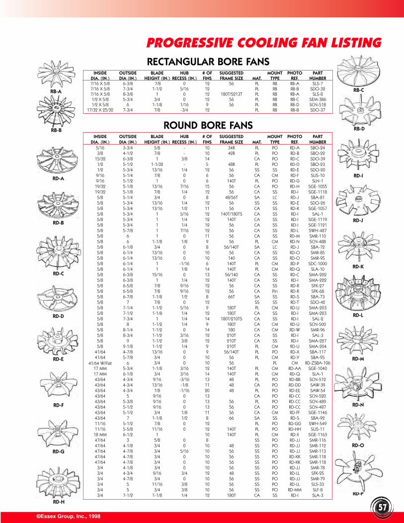
INSIDE OUTSIDE BLADE HUB # OF SUGGESTED MOUNT PHOTO PARTDIA. (IN.) DIA (IN.) HEIGHT (IN.) RECESS (IN.) FINS FRAME SIZE MAT. TYPE REF. NUMBER7/16 X 5/8 6-3/8 7/8 0 12 56 PL RB RB-A SLS-77/16 X 5/8 7-3/4 1-1/2 5/16 12 PL RB RB-B SDO-327/16 X 5/8 8-3/8 1 0 12 180T/S213T PL RB RB-A SLS-81/2 X 5/8 5-3/4 3/4 0 12 56 PL RB RB-C SEM-3861/2 X 5/8 6 1-1/8 1/16 9 56 PL RB RB-D SCN-518
17/32 X 25/32 7-3/4 7/8 -3/4 12 PL RB RB-B SDO-37
INSIDE OUTSIDE BLADE HUB # OF SUGGESTED MOUNT PHOTO PARTDIA. (IN.) DIA (IN.) HEIGHT (IN.) RECESS (IN.) FINS FRAME SIZE MAT. TYPE REF. NUMBER
5/16 3-3/4 5/8 - 10 34R PL PO RD-A SBO-243/8 4-1/2 7/8 - 10 42R PL PO RD-B SBO-22
15/32 6-3/8 1 3/8 14 CA PO RD-C SDO-391/2 5-1/2 1-1/32 - 5 48R PL PO RD-D SBO-231/2 5-3/4 13/16 1/4 12 56 SS SS RD-E SDO-209/16 5-1/4 7/8 0 6 56 CA CM RD-F SUS-109/16 5-1/2 1 0 6 140T PL PO RD-G SLN-119/32 5-1/8 13/16 7/16 15 56 CA PO RD-H SGE-105519/32 5-1/8 7/8 1/4 12 56 CA SS RD-I SGE-11185/8 5-1/4 3/4 0 8 48/56T SA LC RD-J SBA-815/8 5-3/4 13/16 1/4 12 56 SS SS RD-E SDO-265/8 5-3/4 13/16 1/2 11 56 CA SS RD-K SGE-10575/8 5-3/4 1 5/16 12 140T/180TS CA SS RD-I SAL-15/8 5-3/4 1 1/4 12 140T CA SS RD-I SGE-11195/8 5-3/4 1 1/4 12 56 CA SS RD-I SGE-11215/8 5-7/8 1 7/16 12 56 CA SS RD-L SWH-4875/8 6 1 0 11 56 CA SS RD-M SMR-1105/8 6 1-1/8 1/8 9 56 PL CM RD-N SCN-4885/8 6-1/8 3/4 0 8 56/140T SA LC RD-J SBA-725/8 6-1/4 13/16 0 10 56 CA SS RD-O SMR-855/8 6-1/4 13/16 0 10 140 CA SS RD-O SMR-955/8 6-1/4 1 -1/16 6 140T PL CM RD-P SDC-10005/8 6-1/4 1 1/8 14 140T PL CM RD-Q SLA-105/8 6-3/8 15/16 0 13 56/140 CA SS RD-C SMA-2025/8 6-3/8 1 1/4 12 140T CA SS RD-I SMA-2225/8 6-5/8 7/8 9/16 12 56 CA SS RD-R SFK-275/8 6-5/8 7/8 9/16 12 56 CA Pin RD-R SFK-685/8 6-7/8 1-1/8 1/2 8 66T SA SS RD-S SBA-735/8 7 7/8 0 12 SS SS RD-T SDO-425/8 7-1/4 1-1/2 5/16 9 180T PL CM RD-U SMA-2035/8 7-1/2 1-1/8 1/4 12 180T CA SS RD-I SMA-2235/8 7-3/4 1 1/4 14 180T/210TS CA SS RD-I SAL-25/8 8 1-1/2 1/4 9 180T CA CM RD-U SCN-5005/8 8-1/4 1-1/2 0 14 180 CA CM RD-W SMR-965/8 8-3/4 1-1/2 3/16 12 210T CA SS RD-I SAL-35/8 9 1-1/2 3/8 12 210T CA SS RD-I SMA-2275/8 9-1/8 1-1/2 1/4 9 210T PL CM RD-U SMA-204
41/64 4-7/8 13/16 0 9 56/140T PL PO RD-X SBA-11741/64 5-7/8 3/4 0 10 56 PL CM RD-Y SBA-95
41/64 W/Flat 6 3/4 0 10 56 PL CM RD-ZSBA-10617 MM 5-3/4 1-1/8 3/16 12 140T PL CM RD-AA SGE-104017 MM 6-1/8 3/4 3/16 14 140T PL CM RD-Q SLA-143/64 4-3/4 9/16 -3/16 13 48 PL PO RD-BB SCN-51243/64 4-3/4 13/16 -1/8 11 48 CA PO RD-DD SAW-3943/64 4-3/4 7/8 -1/16 20 48 PL PO RD-EE SAW-5443/64 5 9/16 0 13 CA PO RD-CC SCN-52043/64 5-3/8 9/16 0 13 56 PL PO RD-CC SCN-48943/64 5-1/2 9/16 0 13 56 CA PO RD-CC SCN-48743/64 5-1/2 3/4 1/8 11 56 CA CM RD-FF SGE-114643/64 7 1-1/8 1/2 8 66 SA SS RD-S SBA-9211/16 5-1/2 7/8 0 12 PL PO RD-GG SWH-54911/16 5-5/8 11/16 0 12 140T PL PO RD-HH SUS-11
18 MM 6-1/2 1 10 140T PL CM RD-II SGE-116347/64 3 5/8 0 8 SS PO RD-JJ SMR-11647/64 4-1/8 3/4 0 10 48 SS PO RD-JJ SMR-11247/64 4-7/8 3/4 5/16 10 56 SS PO RD-JJ SMR-11347/64 4-7/8 3/4 0 10 56 SS PO RD-KK SMR-11847/64 4-7/8 3/4 0 10 56 SS PO RD-KK SMR-1183/4 4-1/8 3/4 0 10 56 SS PO RD-JJ SMR-783/4 4-3/4 9/16 3/4 12 48 SS PO RD-LL SFK-253/4 4-7/8 3/4 0 10 56 SS PO RD-JJ SMR-793/4 5 11/16 3/8 10 56 SS PO RD-LL SLS-333/4 5 3/4 3/8 10 56 SS PO RD-MM SLF-83/4 7-1/2 1-1/8 1/4 12 180T CA SS RD-I SLA-3 RD-P
RECTANGULAR BORE FANS
ROUND BORE FANS
©Essex Group, Inc., 199857
PROGRESSIVE COOLING FAN LISTING
RB-A
RB-B
RB-C
RB-D
RD-I
RD-J
RD-K
RD-L
RD-M
RD-N
RD-O
RD-H
RD-G
RD-F
RD-D
RD-C
RD-B
RD-E
RD-A
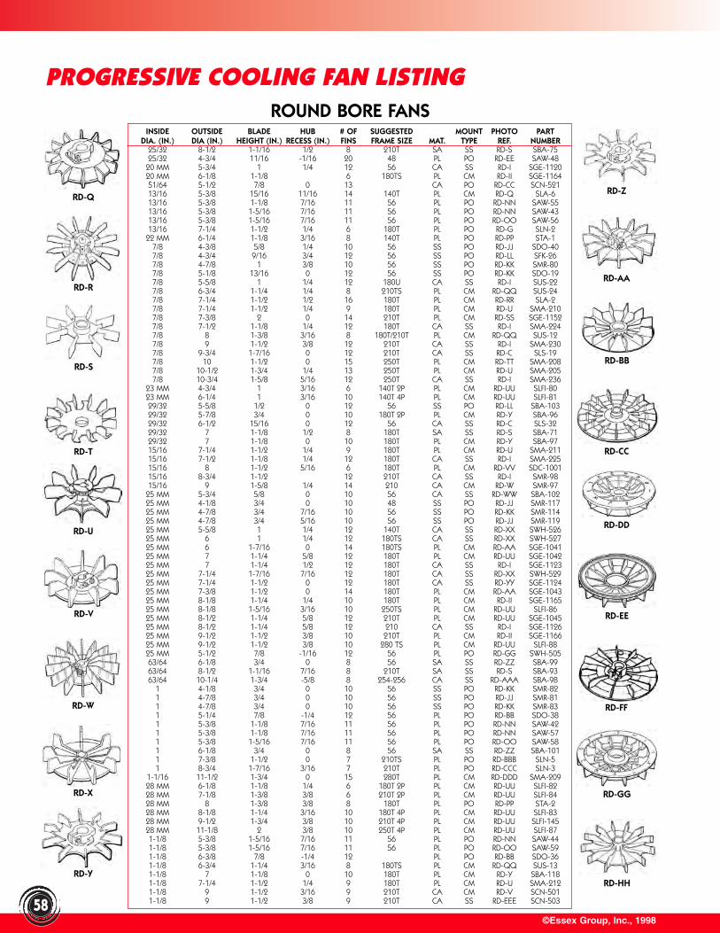
©Essex Group, Inc., 199858
ROUND BORE FANS
PROGRESSIVE COOLING FAN LISTING
INSIDE OUTSIDE BLADE HUB # OF SUGGESTED MOUNT PHOTO PARTDIA. (IN.) DIA (IN.) HEIGHT (IN.) RECESS (IN.) FINS FRAME SIZE MAT. TYPE REF. NUMBER
25/32 8-1/2 1-1/16 1/2 8 210T SA SS RD-S SBA-7525/32 4-3/4 11/16 -1/16 20 48 PL PO RD-EE SAW-48
20 MM 5-3/4 1 1/4 12 56 CA SS RD-I SGE-112020 MM 6-1/8 1-1/8 6 180TS PL CM RD-II SGE-116451/64 5-1/2 7/8 0 13 CA PO RD-CC SCN-52113/16 5-3/8 15/16 11/16 14 140T PL CM RD-Q SLA-613/16 5-3/8 1-1/8 7/16 11 56 PL PO RD-NN SAW-5513/16 5-3/8 1-5/16 7/16 11 56 PL PO RD-NN SAW-4313/16 5-3/8 1-5/16 7/16 11 56 PL PO RD-OO SAW-5613/16 7-1/4 1-1/2 1/4 6 180T PL PO RD-G SLN-2
22 MM 6-1/4 1-1/8 3/16 8 140T PL PO RD-PP STA-17/8 4-3/8 5/8 1/4 10 56 SS PO RD-JJ SDO-407/8 4-3/4 9/16 3/4 12 56 SS PO RD-LL SFK-267/8 4-7/8 1 3/8 10 56 SS PO RD-KK SMR-807/8 5-1/8 13/16 0 12 56 SS PO RD-KK SDO-197/8 5-5/8 1 1/4 12 180U CA SS RD-I SUS-227/8 6-3/4 1-1/4 1/4 8 210TS PL CM RD-QQ SUS-247/8 7-1/4 1-1/2 1/2 16 180T PL CM RD-RR SLA-27/8 7-1/4 1-1/2 1/4 9 180T PL CM RD-U SMA-2107/8 7-3/8 2 0 14 210T PL CM RD-SS SGE-11527/8 7-1/2 1-1/8 1/4 12 180T CA SS RD-I SMA-2247/8 8 1-3/8 3/16 8 180T/210T PL CM RD-QQ SUS-127/8 9 1-1/2 3/8 12 210T CA SS RD-I SMA-2307/8 9-3/4 1-7/16 0 12 210T CA SS RD-C SLS-197/8 10 1-1/2 0 15 250T PL CM RD-TT SMA-2087/8 10-1/2 1-3/4 1/4 13 250T PL CM RD-U SMA-2057/8 10-3/4 1-5/8 5/16 12 250T CA SS RD-I SMA-236
23 MM 4-3/4 1 3/16 6 140T 2P PL CM RD-UU SLFI-8023 MM 6-1/4 1 3/16 10 140T 4P PL CM RD-UU SLFI-8129/32 5-5/8 1/2 0 12 56 SS PO RD-LL SBA-10329/32 5-7/8 3/4 0 10 180T 2P PL CM RD-Y SBA-9629/32 6-1/2 15/16 0 12 56 CA SS RD-C SLS-3229/32 7 1-1/8 1/2 8 180T SA SS RD-S SBA-7129/32 7 1-1/8 0 10 180T PL CM RD-Y SBA-9715/16 7-1/4 1-1/2 1/4 9 180T PL CM RD-U SMA-21115/16 7-1/2 1-1/8 1/4 12 180T CA SS RD-I SMA-22515/16 8 1-1/2 5/16 6 180T PL CM RD-VV SDC-100115/16 8-3/4 1-1/2 12 210T CA SS RD-I SMR-9815/16 9 1-5/8 1/4 14 210 CA CM RD-W SMR-97
25 MM 5-3/4 5/8 0 10 56 CA SS RD-WW SBA-10225 MM 4-1/8 3/4 0 10 48 SS PO RD-JJ SMR-11725 MM 4-7/8 3/4 7/16 10 56 SS PO RD-KK SMR-11425 MM 4-7/8 3/4 5/16 10 56 SS PO RD-JJ SMR-11925 MM 5-5/8 1 1/4 12 140T CA SS RD-XX SWH-52625 MM 6 1 1/4 12 180TS CA SS RD-XX SWH-52725 MM 6 1-7/16 0 14 180TS PL CM RD-AA SGE-104125 MM 7 1-1/4 5/8 12 180T PL CM RD-UU SGE-104225 MM 7 1-1/4 1/2 12 180T CA SS RD-I SGE-112325 MM 7-1/4 1-7/16 7/16 12 180T CA SS RD-XX SWH-52925 MM 7-1/4 1-1/2 0 12 180T CA SS RD-YY SGE-112425 MM 7-3/8 1-1/2 0 14 180T PL CM RD-AA SGE-104325 MM 8-1/8 1-1/4 1/4 10 180T PL CM RD-II SGE-116525 MM 8-1/8 1-5/16 3/16 10 250TS PL CM RD-UU SLFI-8625 MM 8-1/2 1-1/4 5/8 12 210T PL CM RD-UU SGE-104525 MM 8-1/2 1-1/4 5/8 12 210 CA SS RD-I SGE-112625 MM 9-1/2 1-1/2 3/8 10 210T PL CM RD-II SGE-116625 MM 9-1/2 1-1/2 3/8 10 280 TS PL CM RD-UU SLFI-8825 MM 5-1/2 7/8 -1/16 12 56 PL PO RD-GG SWH-50563/64 6-1/8 3/4 0 8 56 SA SS RD-ZZ SBA-9963/64 8-1/2 1-1/16 7/16 8 210T SA SS RD-S SBA-9363/64 10-1/4 1-3/4 -5/8 8 254-256 CA SS RD-AAA SBA-98
1 4-1/8 3/4 0 10 56 SS PO RD-KK SMR-821 4-7/8 3/4 0 10 56 SS PO RD-JJ SMR-811 4-7/8 3/4 0 10 56 SS PO RD-KK SMR-831 5-1/4 7/8 -1/4 12 56 PL PO RD-BB SDO-381 5-3/8 1-1/8 7/16 11 56 PL PO RD-NN SAW-421 5-3/8 1-1/8 7/16 11 56 PL PO RD-NN SAW-571 5-3/8 1-5/16 7/16 11 56 PL PO RD-OO SAW-581 6-1/8 3/4 0 8 56 SA SS RD-ZZ SBA-1011 7-3/8 1-1/2 0 7 210TS PL PO RD-BBB SLN-51 8-3/4 1-7/16 3/16 7 210T PL PO RD-CCC SLN-3
1-1/16 11-1/2 1-3/4 0 15 280T PL CM RD-DDD SMA-20928 MM 6-1/8 1-1/8 1/4 6 180T 2P PL CM RD-UU SLFI-8228 MM 7-1/8 1-3/8 3/8 6 210T 2P PL CM RD-UU SLFI-8428 MM 8 1-3/8 3/8 8 180T PL PO RD-PP STA-228 MM 8-1/8 1-1/4 3/16 10 180T 4P PL CM RD-UU SLFI-8328 MM 9-1/2 1-3/4 3/8 10 210T 4P PL CM RD-UU SLFI-14528 MM 11-1/8 2 3/8 10 250T 4P PL CM RD-UU SLFI-871-1/8 5-3/8 1-5/16 7/16 11 56 PL PO RD-NN SAW-441-1/8 5-3/8 1-5/16 7/16 11 56 PL PO RD-OO SAW-591-1/8 6-3/8 7/8 -1/4 12 PL PO RD-BB SDO-361-1/8 6-3/4 1-1/4 3/16 8 180TS PL CM RD-QQ SUS-131-1/8 7 1-1/8 0 10 180T PL CM RD-Y SBA-1181-1/8 7-1/4 1-1/2 1/4 9 180T PL CM RD-U SMA-2121-1/8 9 1-1/2 3/16 9 210T CA CM RD-V SCN-5011-1/8 9 1-1/2 3/8 9 210T CA SS RD-EEE SCN-503
RD-X
RD-W
RD-V
RD-T
RD-S
RD-R
RD-U
RD-Q
RD-Y
RD-FF
RD-EE
RD-CC
RD-BB
RD-AA
RD-DD
RD-Z
RD-GG
RD-HH
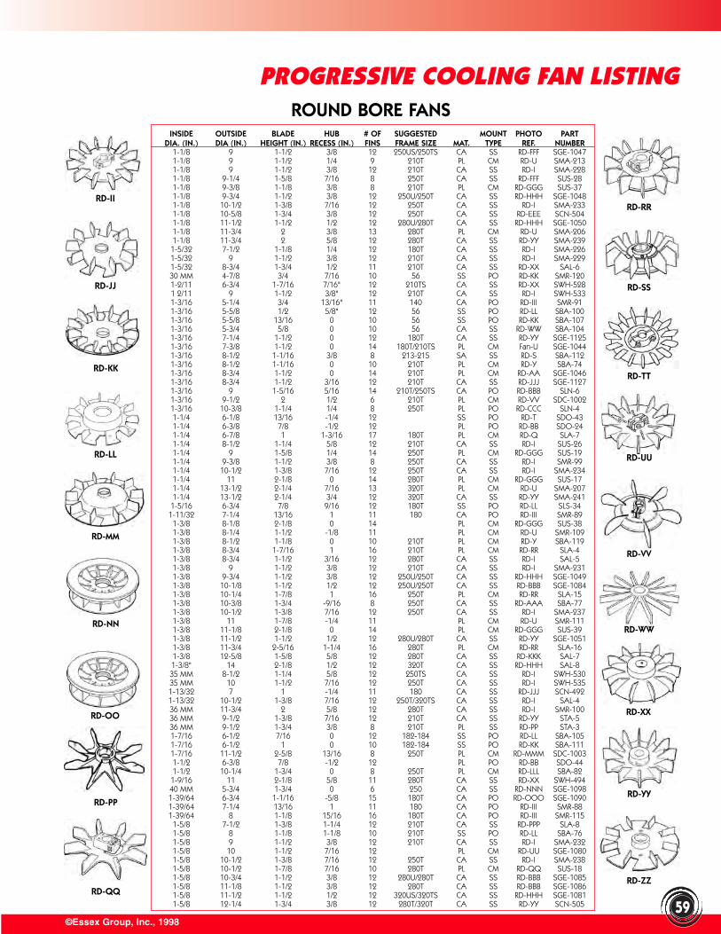
©Essex Group, Inc., 199859
INSIDE OUTSIDE BLADE HUB # OF SUGGESTED MOUNT PHOTO PARTDIA. (IN.) DIA (IN.) HEIGHT (IN.) RECESS (IN.) FINS FRAME SIZE MAT. TYPE REF. NUMBER
1-1/8 9 1-1/2 3/8 12 250US/250TS CA SS RD-FFF SGE-10471-1/8 9 1-1/2 1/4 9 210T PL CM RD-U SMA-2131-1/8 9 1-1/2 3/8 12 210T CA SS RD-I SMA-2281-1/8 9-1/4 1-5/8 7/16 8 250T CA SS RD-FFF SUS-281-1/8 9-3/8 1-1/8 3/8 8 210T PL CM RD-GGG SUS-371-1/8 9-3/4 1-1/2 3/8 12 250U/250T CA SS RD-HHH SGE-10481-1/8 10-1/2 1-3/8 7/16 12 250T CA SS RD-I SMA-2331-1/8 10-5/8 1-3/4 3/8 12 250T CA SS RD-EEE SCN-5041-1/8 11-1/2 1-1/2 1/2 12 280U/280T CA SS RD-HHH SGE-10501-1/8 11-3/4 2 3/8 13 280T PL CM RD-U SMA-2061-1/8 11-3/4 2 5/8 12 280T CA SS RD-YY SMA-2391-5/32 7-1/2 1-1/8 1/4 12 180T CA SS RD-I SMA-2261-5/32 9 1-1/2 3/8 12 210T CA SS RD-I SMA-2291-5/32 8-3/4 1-3/4 1/2 11 210T CA SS RD-XX SAL-630 MM 4-7/8 3/4 7/16 10 56 SS PO RD-KK SMR-1201-2/11 6-3/4 1-7/16 7/16" 12 210TS CA SS RD-XX SWH-5281 2/11 9 1-1/2 3/8" 12 210T CA SS RD-I SWH-5331-3/16 5-1/4 3/4 13/16" 11 140 CA PO RD-III SMR-911-3/16 5-5/8 1/2 5/8" 12 56 SS PO RD-LL SBA-1001-3/16 5-5/8 13/16 0 10 56 SS PO RD-KK SBA-1071-3/16 5-3/4 5/8 0 10 56 CA SS RD-WW SBA-1041-3/16 7-1/4 1-1/2 0 12 180T CA SS RD-YY SGE-11251-3/16 7-3/8 1-1/2 0 14 180T/210TS PL CM Fan-U SGE-10441-3/16 8-1/2 1-1/16 3/8 8 213-215 SA SS RD-S SBA-1121-3/16 8-1/2 1-1/16 0 10 210T PL CM RD-Y SBA-741-3/16 8-3/4 1-1/2 0 14 210T PL CM RD-AA SGE-10461-3/16 8-3/4 1-1/2 3/16 12 210T CA SS RD-JJJ SGE-11271-3/16 9 1-5/16 5/16 14 210T/250TS CA PO RD-BBB SLN-61-3/16 9-1/2 2 1/2 6 210T PL CM RD-VV SDC-10021-3/16 10-3/8 1-1/4 1/4 8 250T PL PO RD-CCC SLN-41-1/4 6-1/8 13/16 -1/4 12 SS PO RD-T SDO-431-1/4 6-3/8 7/8 -1/2 12 PL PO RD-BB SDO-241-1/4 6-7/8 1 1-3/16 17 180T PL CM RD-Q SLA-71-1/4 8-1/2 1-1/4 5/8 12 210T CA SS RD-I SUS-261-1/4 9 1-5/8 1/4 14 250T PL CM RD-GGG SUS-191-1/4 9-3/8 1-1/2 3/8 8 250T CA SS RD-I SMR-991-1/4 10-1/2 1-3/8 7/16 12 250T CA SS RD-I SMA-2341-1/4 11 2-1/8 0 14 280T PL CM RD-GGG SUS-171-1/4 13-1/2 2-1/4 7/16 13 320T PL CM RD-U SMA-2071-1/4 13-1/2 2-1/4 3/4 12 320T CA SS RD-YY SMA-2411-5/16 6-3/4 7/8 9/16 12 180T SS PO RD-LL SLS-34
1-11/32 7-1/4 13/16 1 11 180 CA PO RD-III SMR-891-3/8 8-1/8 2-1/8 0 14 PL CM RD-GGG SUS-381-3/8 8-1/4 1-1/2 -1/8 11 PL CM RD-U SMR-1091-3/8 8-1/2 1-1/8 0 10 210T PL CM RD-Y SBA-1191-3/8 8-3/4 1-7/16 1 16 210T PL CM RD-RR SLA-41-3/8 8-3/4 1-1/2 3/16 12 280T CA SS RD-I SAL-51-3/8 9 1-1/2 3/8 12 210T CA SS RD-I SMA-2311-3/8 9-3/4 1-1/2 3/8 12 250U/250T CA SS RD-HHH SGE-10491-3/8 10-1/8 1-1/2 1/2 12 250U/250T CA SS RD-BBB SGE-10841-3/8 10-1/4 1-7/8 1 16 250T PL CM RD-RR SLA-151-3/8 10-3/8 1-3/4 -9/16 8 250T CA SS RD-AAA SBA-771-3/8 10-1/2 1-3/8 7/16 12 250T CA SS RD-I SMA-2371-3/8 11 1-7/8 -1/4 11 PL CM RD-U SMR-1111-3/8 11-1/8 2-1/8 0 14 PL CM RD-GGG SUS-391-3/8 11-1/2 1-1/2 1/2 12 280U/280T CA SS RD-YY SGE-10511-3/8 11-3/4 2-5/16 1-1/4 16 280T PL CM RD-RR SLA-161-3/8 12-5/8 1-5/8 5/8 12 280T CA SS RD-KKK SAL-71-3/8" 14 2-1/8 1/2 12 320T CA SS RD-HHH SAL-835 MM 8-1/2 1-1/4 5/8 12 250TS CA SS RD-I SWH-53035 MM 10 1-1/2 7/16 12 250T CA SS RD-I SWH-5351-13/32 7 1 -1/4 11 180 CA SS RD-JJJ SCN-4921-13/32 10-1/2 1-3/8 7/16 12 250T/320TS CA SS RD-I SAL-436 MM 11-3/4 2 5/8 12 280T CA SS RD-I SMR-10036 MM 9-1/2 1-3/8 7/16 12 210T CA SS RD-YY STA-536 MM 9-1/2 1-3/4 3/8 8 210T PL SS RD-PP STA-31-7/16 6-1/2 7/16 0 12 182-184 SS PO RD-LL SBA-1051-7/16 6-1/2 1 0 10 182-184 SS PO RD-KK SBA-1111-7/16 11-1/2 2-5/8 13/16 8 250T PL CM RD-MMM SDC-10031-1/2 6-3/8 7/8 -1/2 12 PL PO RD-BB SDO-441-1/2 10-1/4 1-3/4 0 8 250T PL CM RD-LLL SBA-821-9/16 11 2-1/8 5/8 11 280T CA SS RD-XX SWH-49440 MM 5-3/4 1-3/4 0 6 250 CA SS RD-NNN SGE-10981-39/64 6-3/4 1-1/16 -5/8 15 180T CA PO RD-OOO SGE-10901-39/64 7-1/4 13/16 1 11 180 CA PO RD-III SMR-881-39/64 8 1-1/8 15/16 16 180T CA PO RD-III SMR-1151-5/8 7-1/2 1-3/8 1-1/4 12 210T CA SS RD-PPP SLA-81-5/8 8 1-1/8 1-1/8 10 210T SS PO RD-LL SBA-761-5/8 9 1-1/2 3/8 12 210T CA SS RD-I SMA-2321-5/8 10 1-1/2 7/16 12 PL CM RD-UU SGE-10801-5/8 10-1/2 1-3/8 7/16 12 250T CA SS RD-I SMA-2381-5/8 10-1/2 1-7/8 7/16 10 280T PL CM RD-QQ SUS-181-5/8 10-3/4 1-1/2 3/8 12 280U/280T CA SS RD-BBB SGE-10851-5/8 11-1/8 1-1/2 3/8 12 280T CA SS RD-BBB SGE-10861-5/8 11-1/2 1-1/2 1/2 12 320US/320TS CA SS RD-HHH SGE-10811-5/8 12-1/4 1-3/4 3/8 12 280T/320T CA SS RD-YY SCN-505
ROUND BORE FANS
PROGRESSIVE COOLING FAN LISTING
RD-OO
RD-NN
RD-LL
RD-KK
RD-JJ
RD-MM
RD-II
RD-PP
RD-QQ
RD-XX
RD-WW
RD-UU
RD-TT
RD-SS
RD-VV
RD-RR
RD-YY
RD-ZZ
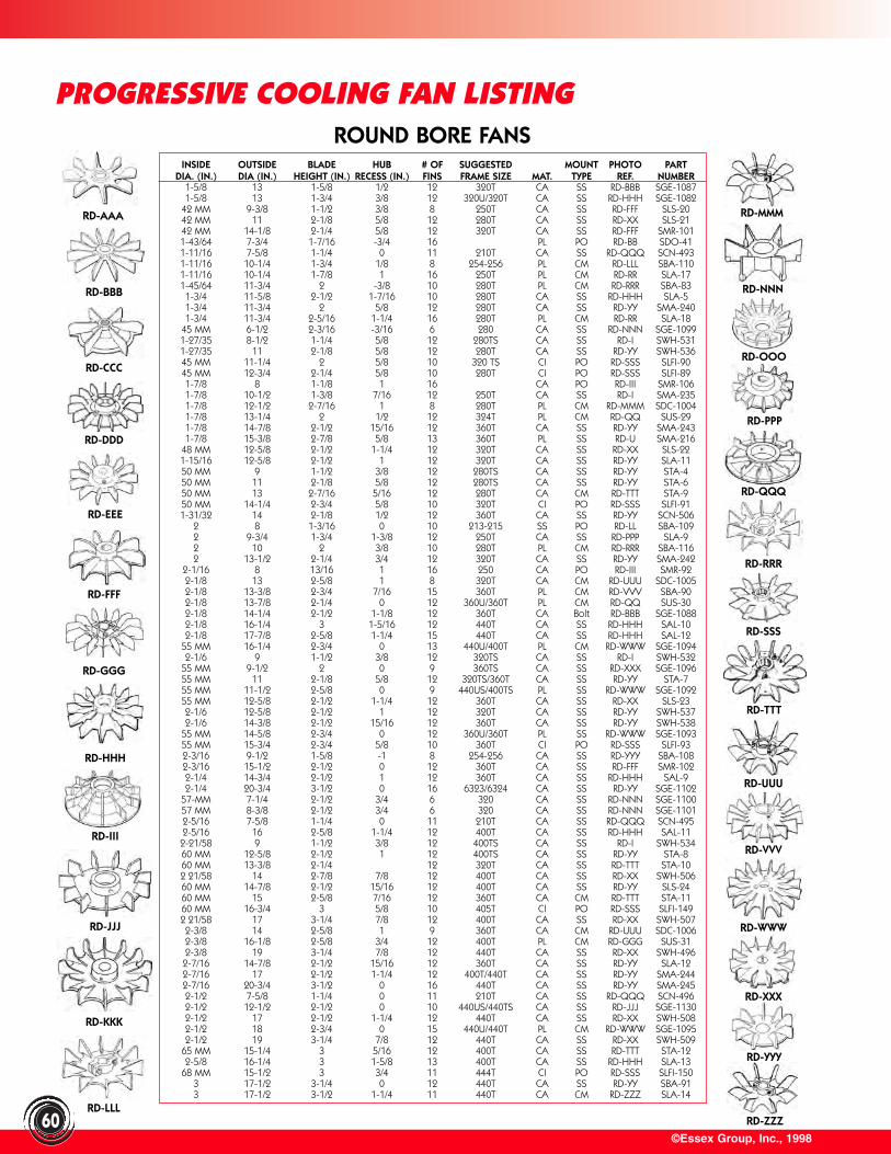
©Essex Group, Inc., 199860
INSIDE OUTSIDE BLADE HUB # OF SUGGESTED MOUNT PHOTO PARTDIA. (IN.) DIA (IN.) HEIGHT (IN.) RECESS (IN.) FINS FRAME SIZE MAT. TYPE REF. NUMBER
1-5/8 13 1-5/8 1/2 12 320T CA SS RD-BBB SGE-10871-5/8 13 1-3/4 3/8 12 320U/320T CA SS RD-HHH SGE-1082
42 MM 9-3/8 1-1/2 3/8 8 250T CA SS RD-FFF SLS-2042 MM 11 2-1/8 5/8 12 280T CA SS RD-XX SLS-2142 MM 14-1/8 2-1/4 5/8 12 320T CA SS RD-FFF SMR-1011-43/64 7-3/4 1-7/16 -3/4 16 PL PO RD-BB SDO-411-11/16 7-5/8 1-1/4 0 11 210T CA SS RD-QQQ SCN-4931-11/16 10-1/4 1-3/4 1/8 8 254-256 PL CM RD-LLL SBA-1101-11/16 10-1/4 1-7/8 1 16 250T PL CM RD-RR SLA-171-45/64 11-3/4 2 -3/8 10 280T PL CM RD-RRR SBA-831-3/4 11-5/8 2-1/2 1-7/16 10 280T CA SS RD-HHH SLA-51-3/4 11-3/4 2 5/8 12 280T CA SS RD-YY SMA-2401-3/4 11-3/4 2-5/16 1-1/4 16 280T PL CM RD-RR SLA-18
45 MM 6-1/2 2-3/16 -3/16 6 280 CA SS RD-NNN SGE-10991-27/35 8-1/2 1-1/4 5/8 12 280TS CA SS RD-I SWH-5311-27/35 11 2-1/8 5/8 12 280T CA SS RD-YY SWH-53645 MM 11-1/4 2 5/8 10 320 TS CI PO RD-SSS SLFI-9045 MM 12-3/4 2-1/4 5/8 10 280T CI PO RD-SSS SLFI-891-7/8 8 1-1/8 1 16 CA PO RD-III SMR-1061-7/8 10-1/2 1-3/8 7/16 12 250T CA SS RD-I SMA-2351-7/8 12-1/2 2-7/16 1 8 280T PL CM RD-MMM SDC-10041-7/8 13-1/4 2 1/2 12 324T PL CM RD-QQ SUS-291-7/8 14-7/8 2-1/2 15/16 12 360T CA SS RD-YY SMA-2431-7/8 15-3/8 2-7/8 5/8 13 360T PL SS RD-U SMA-216
48 MM 12-5/8 2-1/2 1-1/4 12 320T CA SS RD-XX SLS-221-15/16 12-5/8 2-1/2 1 12 320T CA SS RD-YY SLA-1150 MM 9 1-1/2 3/8 12 280TS CA SS RD-YY STA-450 MM 11 2-1/8 5/8 12 280TS CA SS RD-YY STA-650 MM 13 2-7/16 5/16 12 280T CA CM RD-TTT STA-950 MM 14-1/4 2-3/4 5/8 10 320T CI PO RD-SSS SLFI-911-31/32 14 2-1/8 1/2 12 360T CA SS RD-YY SCN-506
2 8 1-3/16 0 10 213-215 SS PO RD-LL SBA-1092 9-3/4 1-3/4 1-3/8 12 250T CA SS RD-PPP SLA-92 10 2 3/8 10 280T PL CM RD-RRR SBA-1162 13-1/2 2-1/4 3/4 12 320T CA SS RD-YY SMA-242
2-1/16 8 13/16 1 16 250 CA PO RD-III SMR-922-1/8 13 2-5/8 1 8 320T CA CM RD-UUU SDC-10052-1/8 13-3/8 2-3/4 7/16 15 360T PL CM RD-VVV SBA-902-1/8 13-7/8 2-1/4 0 12 360U/360T PL CM RD-QQ SUS-302-1/8 14-1/4 2-1/2 1-1/8 12 360T CA Bolt RD-BBB SGE-10882-1/8 16-1/4 3 1-5/16 12 440T CA SS RD-HHH SAL-102-1/8 17-7/8 2-5/8 1-1/4 15 440T CA SS RD-HHH SAL-12
55 MM 16-1/4 2-3/4 0 13 440U/400T PL CM RD-WWW SGE-10942-1/6 9 1-1/2 3/8 12 320TS CA SS RD-I SWH-532
55 MM 9-1/2 2 0 9 360TS CA SS RD-XXX SGE-109655 MM 11 2-1/8 5/8 12 320TS/360T CA SS RD-YY STA-755 MM 11-1/2 2-5/8 0 9 440US/400TS PL SS RD-WWW SGE-109255 MM 12-5/8 2-1/2 1-1/4 12 360T CA SS RD-XX SLS-232-1/6 12-5/8 2-1/2 1 12 320T CA SS RD-YY SWH-5372-1/6 14-3/8 2-1/2 15/16 12 360T CA SS RD-YY SWH-538
55 MM 14-5/8 2-3/4 0 12 360U/360T PL SS RD-WWW SGE-109355 MM 15-3/4 2-3/4 5/8 10 360T CI PO RD-SSS SLFI-932-3/16 9-1/2 1-5/8 -1 8 254-256 CA SS RD-YYY SBA-1082-3/16 15-1/2 2-1/2 0 12 360T CA SS RD-FFF SMR-1022-1/4 14-3/4 2-1/2 1 12 360T CA SS RD-HHH SAL-92-1/4 20-3/4 3-1/2 0 16 6323/6324 CA SS RD-YY SGE-1102
57-MM 7-1/4 2-1/2 3/4 6 320 CA SS RD-NNN SGE-110057 MM 8-3/8 2-1/2 3/4 6 320 CA SS RD-NNN SGE-11012-5/16 7-5/8 1-1/4 0 11 210T CA SS RD-QQQ SCN-4952-5/16 16 2-5/8 1-1/4 12 400T CA SS RD-HHH SAL-112-21/58 9 1-1/2 3/8 12 400TS CA SS RD-I SWH-53460 MM 12-5/8 2-1/2 1 12 400TS CA SS RD-YY STA-860 MM 13-3/8 2-1/4 12 320T CA SS RD-TTT STA-102 21/58 14 2-7/8 7/8 12 400T CA SS RD-XX SWH-50660 MM 14-7/8 2-1/2 15/16 12 400T CA SS RD-YY SLS-2460 MM 15 2-5/8 7/16 12 360T CA CM RD-TTT STA-1160 MM 16-3/4 3 5/8 10 405T CI PO RD-SSS SLFI-1492 21/58 17 3-1/4 7/8 12 400T CA SS RD-XX SWH-5072-3/8 14 2-5/8 1 9 360T CA CM RD-UUU SDC-10062-3/8 16-1/8 2-5/8 3/4 12 400T PL CM RD-GGG SUS-312-3/8 19 3-1/4 7/8 12 440T CA SS RD-XX SWH-4962-7/16 14-7/8 2-1/2 15/16 12 360T CA SS RD-YY SLA-122-7/16 17 2-1/2 1-1/4 12 400T/440T CA SS RD-YY SMA-2442-7/16 20-3/4 3-1/2 0 16 440T CA SS RD-YY SMA-2452-1/2 7-5/8 1-1/4 0 11 210T CA SS RD-QQQ SCN-4962-1/2 12-1/2 2-1/2 0 10 440US/440TS CA SS RD-JJJ SGE-11302-1/2 17 2-1/2 1-1/4 12 440T CA SS RD-XX SWH-5082-1/2 18 2-3/4 0 15 440U/440T PL CM RD-WWW SGE-10952-1/2 19 3-1/4 7/8 12 440T CA SS RD-XX SWH-509
65 MM 15-1/4 3 5/16 12 400T CA SS RD-TTT STA-122-5/8 16-1/4 3 1-5/8 13 400T CA SS RD-HHH SLA-13
68 MM 15-1/2 3 3/4 11 444T CI PO RD-SSS SLFI-1503 17-1/2 3-1/4 0 12 440T CA SS RD-YY SBA-913 17-1/2 3-1/2 1-1/4 11 440T CA CM RD-ZZZ SLA-14
ROUND BORE FANS
PROGRESSIVE COOLING FAN LISTING
RD-AAA
RD-BBB
RD-CCC
RD-DDD
RD-EEE
RD-FFF
RD-GGG
RD-HHH
RD-III
RD-JJJ
RD-KKK
RD-LLL
RD-MMM
RD-NNN
RD-OOO
RD-PPP
RD-QQQ
RD-RRR
RD-SSS
RD-TTT
RD-UUU
RD-VVV
RD-WWW
RD-XXX
RD-YYY
RD-ZZZ
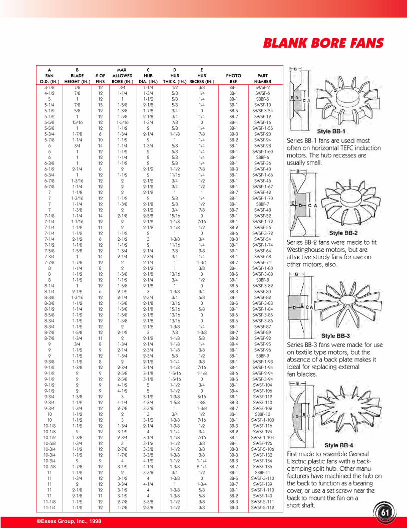
First made to resemble GeneralElectric plastic fans with a back-clamping split hub. Other manu-facturers have machined the hub onthe back to function as a bearingcover, or use a set screw near theback to mount the fan on ashort shaft.
©Essex Group, Inc., 1998
BLANK BORE FANS
61
A B MAX. C D EFAN BLADE # OF ALLOWED HUB HUB HUB PHOTO PART
O.D. (IN.) HEIGHT (IN.) FINS BORE (IN.) DIA. (IN.) THICK. (IN.) RECESS (IN.) REF. NUMBER3-1/8 7/8 12 3/4 1-1/4 1/2 3/8 BB-1 SWSF-24-1/2 7/8 12 1-1/4 1-3/4 5/8 1/4 BB-1 SWSF-6
5 1 12 1 1-1/2 5/8 1/4 BB-1 SBBF-55-1/4 7/8 15 1-5/8 2-1/8 5/8 1/4 BB-1 SWSF-105-1/2 5/8 12 1-3/8 1-7/8 3/4 0 BB-5 SWSF-3-545-1/2 1 12 1-5/8 2-1/8 3/4 1/4 BB-7 SWSF-125-5/8 15/16 12 1-5/16 1-3/4 7/8 0 BB-1 SWSF-165-5/8 1 12 1-1/2 2 5/8 1/4 BB-1 SWSF-1-555-3/4 1-7/8 6 1-3/4 2-1/4 1-1/8 7/8 BB-3 SWSF-205-7/8 1-1/4 10 1-1/2 2 1 1/4 BB-2 SWSF-24
6 3/4 14 1-1/4 1-3/4 5/8 1/4 BB-1 SWSF-286 1 12 1-1/2 2 5/8 1/4 BB-1 SWSF-1-606 1 12 1-1/4 2 5/8 1/4 BB-1 SBBF-6
6-3/8 1 12 1-1/2 2 5/8 1/4 BB-1 SWSF-366-1/2 2-1/4 6 2 2-1/2 1-1/2 7/8 BB-3 SWSF-406-3/4 1 12 1-1/2 2 11/16 1/4 BB-1 SWSF-1-666-7/8 1-3/16 12 2 2-1/2 3/4 1/2 BB-1 SWSF-466-7/8 1-1/4 12 2 2-1/2 3/4 1/2 BB-1 SWSF-1-67
7 1-1/8 12 2 2-1/2 1 1 BB-7 SWSF-427 1-3/16 12 1-1/2 2 5/8 1/4 BB-1 SWSF-1-707 1-1/4 12 1-3/8 2-1/8 5/8 1/2 BB-1 SBBF-77 1-3/8 12 2 2-1/2 3/4 7/8 BB-7 SWSF-48
7-1/8 1-1/4 14 2-1/8 2-5/8 15/16 0 BB-1 SWSF-527-1/4 1-7/16 12 2 2-1/2 1-1/8 7/16 BB-1 SWSF-1-727-1/4 1-1/2 11 2 2-1/2 1-1/8 1/2 BB-2 SWSF-567-1/4 1-1/2 12 1-1/2 2 1 0 BB-6 SWSF-3-727-1/4 2-1/2 6 2-1/2 3 1-3/8 3/4 BB-3 SWSF-547-1/2 1-1/8 12 1-1/2 2 11/16 1/4 BB-1 SWSF-1-747-5/8 1-5/8 12 1-3/4 2-1/4 7/8 3/8 BB-1 SWSF-647-3/4 1 14 2-1/4 2-3/4 3/4 1/4 BB-1 SWSF-687-7/8 1-7/8 19 2 2-1/4 1 1-3/4 BB-7 SWSF-74
8 1-1/4 8 2 2-1/2 1 3/8 BB-1 SWSF-1-808 1-1/2 12 1-5/8 2-1/8 13/16 0 BB-5 SWSF-3-808 1-1/2 12 1-1/2 2-1/4 3/4 1/2 BB-1 SBBF-8
8-1/4 1 12 1-5/8 2-1/8 1 0 BB-5 SWSF-3-828-1/4 2-1/2 6 2-1/2 3 1-3/8 3/4 BB-3 SWSF-808-3/8 1-3/16 12 2-1/4 2-3/4 3/4 5/8 BB-1 SWSF-828-3/8 1-1/2 12 1-5/8 2-1/8 13/16 0 BB-5 SWSF-3-838-1/2 1-1/4 12 1-5/8 2-1/8 15/16 5/8 BB-1 SWSF-1-848-5/8 1-1/2 12 1-5/8 2-1/8 13/16 0 BB-5 SWSF-3-858-3/4 1-1/2 12 1-5/8 2-1/8 13/16 0 BB-5 SWSF-3-868-3/4 1-1/2 12 2 2-1/2 1-3/8 1/4 BB-1 SWSF-878-7/8 1-5/8 12 2-1/2 3 7/8 1-3/8 BB-7 SWSF-898-7/8 1-3/4 11 2 2-1/2 1-1/8 5/8 BB-2 SWSF-92
9 3/4 8 1-3/4 2-1/4 1-1/8 1/4 BB-4 SWSF-959 1-1/2 9 2-1/4 2-3/4 1-1/8 3/8 BB-1 SWSF-969 1-1/2 12 1-3/4 2-3/4 5/8 1/2 BB-1 SBBF-9
9-3/8 1-1/2 8 2 2-1/2 1-1/4 3/8 BB-1 SWSF-1-939-1/2 1-3/8 12 2-3/4 3-1/4 1-1/8 7/16 BB-1 SWSF-1-949-1/2 2 9 2-5/8 3-1/8 1-5/16 1-1/8 BB-6 SWSF-2-949-1/2 2 12 2-5/8 3-1/8 1-5/16 0 BB-5 SWSF-3-949-1/2 2 9 4-1/2 5 1-1/2 3/4 BB-1 SWSF-1049-1/2 2 9 4-1/2 5 1-1/2 0 BB-4 SWSF-1069-3/4 1-3/8 12 3 3-1/2 1-3/8 5/16 BB-1 SWSF-1129-3/4 1-1/2 12 4-1/4 4-3/4 1-5/8 -3/8 BB-3 SWSF-1109-3/4 1-3/4 12 2-7/8 3-3/8 1 1-3/8 BB-7 SWSF-102
10 1-1/2 12 2 3 3/4 1/2 BB-1 SBBF-1010 1-1/2 12 3 3-1/2 1-3/8 7/16 BB-1 SWSF-1-100
10-1/8 1-1/2 12 1-3/4 2-1/4 1-3/8 1/2 BB-3 SWSF-11610-1/8 2 12 3-1/2 4 1-1/4 3/4 BB-2 SWSF-12410-1/2 1-3/8 12 2-3/4 3-1/4 1-1/8 7/16 BB-1 SWSF-1-10410-5/8 1-3/4 12 3 3-1/2 1-1/2 3/8 BB-1 SWSF-12610-3/4 1-1/2 12 2-7/8 3-3/8 1-1/2 3/8 BB-3 SWSF-5-10610-3/4 1-1/2 12 1-7/8 3-3/8 1-3/8 3/8 BB-3 SWSF-13210-3/4 2 9 4 4-1/2 1-1/2 1-1/4 BB-3 SWSF-13410-7/8 1-7/8 12 3-1/2 4-1/4 1-3/8 2-1/4 BB-7 SWSF-136
11 1-1/2 12 2 3-3/8 3/4 1/2 BB-1 SBBF-1111 1-3/4 12 3-1/2 4 1-3/8 0 BB-5 SWSF-3-11011 2 12 3-3/4 4-1/4 1 1-3/4 BB-7 SWSF-13911 2-1/8 12 3-1/2 4 1-3/8 5/8 BB-1 SWSF-1-11011 2-1/8 11 3-1/2 4 1-3/8 5/8 BB-2 SWSF-140
11-1/8 1-1/2 12 2-7/8 3-3/8 1-1/2 3/8 BB-3 SWSF-5-11111-1/4 1-1/2 12 1-7/8 2-3/8 1-1/2 3/8 BB-3 SWSF-5-112
Series BB-1 fans are used mostoften on horizontal TEFC inductionmotors. The hub recesses areusually small.
Series BB-2 fans were made to fitWestinghouse motors, but areattractive sturdy fans for use onother motors, also.
Series BB-3 fans were made for useon textile type motors, but theabsence of a back plate makes itideal for replacing external fan blades.
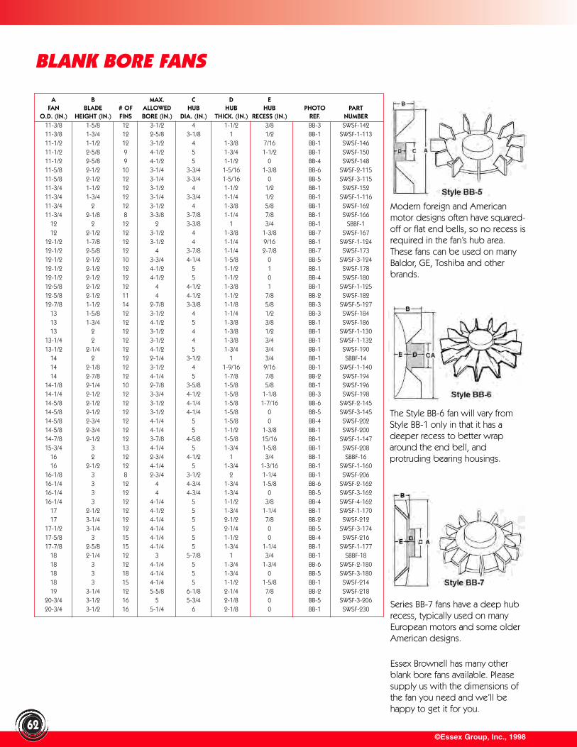
©Essex Group, Inc., 199862
BLANK BORE FANS
A B MAX. C D EFAN BLADE # OF ALLOWED HUB HUB HUB PHOTO PART
O.D. (IN.) HEIGHT (IN.) FINS BORE (IN.) DIA. (IN.) THICK. (IN.) RECESS (IN.) REF. NUMBER11-3/8 1-5/8 12 3-1/2 4 1-1/2 3/8 BB-3 SWSF-14211-3/8 1-3/4 12 2-5/8 3-1/8 1 1/2 BB-1 SWSF-1-11311-1/2 1-1/2 12 3-1/2 4 1-3/8 7/16 BB-1 SWSF-14611-1/2 2-5/8 9 4-1/2 5 1-3/4 1-1/2 BB-1 SWSF-15011-1/2 2-5/8 9 4-1/2 5 1-1/2 0 BB-4 SWSF-14811-5/8 2-1/2 10 3-1/4 3-3/4 1-5/16 1-3/8 BB-6 SWSF-2-11511-5/8 2-1/2 12 3-1/4 3-3/4 1-5/16 0 BB-5 SWSF-3-11511-3/4 1-1/2 12 3-1/2 4 1-1/2 1/2 BB-1 SWSF-15211-3/4 1-3/4 12 3-1/4 3-3/4 1-1/4 1/2 BB-1 SWSF-1-11611-3/4 2 12 3-1/2 4 1-3/8 5/8 BB-1 SWSF-16211-3/4 2-1/8 8 3-3/8 3-7/8 1-1/4 7/8 BB-1 SWSF-166
12 2 12 2 3-3/8 1 3/4 BB-1 SBBF-112 2-1/2 12 3-1/2 4 1-3/8 1-3/8 BB-7 SWSF-167
12-1/2 1-7/8 12 3-1/2 4 1-1/4 9/16 BB-1 SWSF-1-12412-1/2 2-5/8 12 4 3-7/8 1-1/4 2-7/8 BB-7 SWSF-17312-1/2 2-1/2 10 3-3/4 4-1/4 1-5/8 0 BB-5 SWSF-3-12412-1/2 2-1/2 12 4-1/2 5 1-1/2 1 BB-1 SWSF-17812-1/2 2-1/2 12 4-1/2 5 1-1/2 0 BB-4 SWSF-18012-5/8 2-1/2 12 4 4-1/2 1-3/8 1 BB-1 SWSF-1-12512-5/8 2-1/2 11 4 4-1/2 1-1/2 7/8 BB-2 SWSF-18212-7/8 1-1/2 14 2-7/8 3-3/8 1-1/8 5/8 BB-3 SWSF-5-127
13 1-5/8 12 3-1/2 4 1-1/4 1/2 BB-3 SWSF-18413 1-3/4 12 4-1/2 5 1-3/8 3/8 BB-1 SWSF-18613 2 12 3-1/2 4 1-3/8 1/2 BB-1 SWSF-1-130
13-1/4 2 12 3-1/2 4 1-3/8 3/4 BB-1 SWSF-1-13213-1/2 2-1/4 12 4-1/2 5 1-3/4 3/4 BB-1 SWSF-190
14 2 12 2-1/4 3-1/2 1 3/4 BB-1 SBBF-1414 2-1/8 12 3-1/2 4 1-9/16 9/16 BB-1 SWSF-1-14014 2-7/8 12 4-1/4 5 1-7/8 7/8 BB-2 SWSF-194
14-1/8 2-1/4 10 2-7/8 3-5/8 1-5/8 5/8 BB-1 SWSF-19614-1/4 2-1/2 12 3-3/4 4-1/2 1-5/8 1-1/8 BB-3 SWSF-19814-5/8 2-1/2 12 3-1/2 4-1/4 1-5/8 1-7/16 BB-6 SWSF-2-14514-5/8 2-1/2 12 3-1/2 4-1/4 1-5/8 0 BB-5 SWSF-3-14514-5/8 2-3/4 12 4-1/4 5 1-5/8 0 BB-4 SWSF-20214-5/8 2-3/4 12 4-1/4 5 1-1/2 1-3/8 BB-1 SWSF-20014-7/8 2-1/2 12 3-7/8 4-5/8 1-5/8 15/16 BB-1 SWSF-1-14715-3/4 3 13 4-1/4 5 1-3/4 1-5/8 BB-1 SWSF-208
16 2 12 2-3/4 4-1/2 1 3/4 BB-1 SBBF-1616 2-1/2 12 4-1/4 5 1-3/4 1-3/16 BB-1 SWSF-1-160
16-1/8 3 8 2-3/4 3-1/2 2 1-1/4 BB-1 SWSF-20616-1/4 3 12 4 4-3/4 1-3/4 1-5/8 BB-6 SWSF-2-16216-1/4 3 12 4 4-3/4 1-3/4 0 BB-5 SWSF-3-16216-1/4 3 12 4-1/4 5 1-1/2 3/8 BB-4 SWSF-4-162
17 2-1/2 12 4-1/2 5 1-3/4 1-1/4 BB-1 SWSF-1-17017 3-1/4 12 4-1/4 5 2-1/2 7/8 BB-2 SWSF-212
17-1/2 3-1/4 12 4-1/4 5 2-1/4 0 BB-5 SWSF-3-17417-5/8 3 15 4-1/4 5 1-1/2 0 BB-4 SWSF-21617-7/8 2-5/8 15 4-1/4 5 1-3/4 1-1/4 BB-1 SWSF-1-177
18 2-1/4 12 3 5-7/8 1 3/4 BB-1 SBBF-1818 3 12 4-1/4 5 1-3/4 1-3/4 BB-6 SWSF-2-18018 3 18 4-1/4 5 1-3/4 0 BB-5 SWSF-3-18018 3 15 4-1/4 5 1-1/2 1-5/8 BB-1 SWSF-21419 3-1/4 12 5-5/8 6-1/8 2-1/4 7/8 BB-2 SWSF-218
20-3/4 3-1/2 16 5 5-3/4 2-1/8 0 BB-5 SWSF-3-20620-3/4 3-1/2 16 5-1/4 6 2-1/8 0 BB-1 SWSF-230
Series BB-7 fans have a deep hubrecess, typically used on manyEuropean motors and some olderAmerican designs.
Modern foreign and Americanmotor designs often have squared-off or flat end bells, so no recess isrequired in the fan’s hub area.These fans can be used on manyBaldor, GE, Toshiba and otherbrands.
The Style BB-6 fan will vary fromStyle BB-1 only in that it has adeeper recess to better wraparound the end bell, andprotruding bearing housings.
Essex Brownell has many otherblank bore fans available. Pleasesupply us with the dimensions ofthe fan you need and we’ll behappy to get it for you.
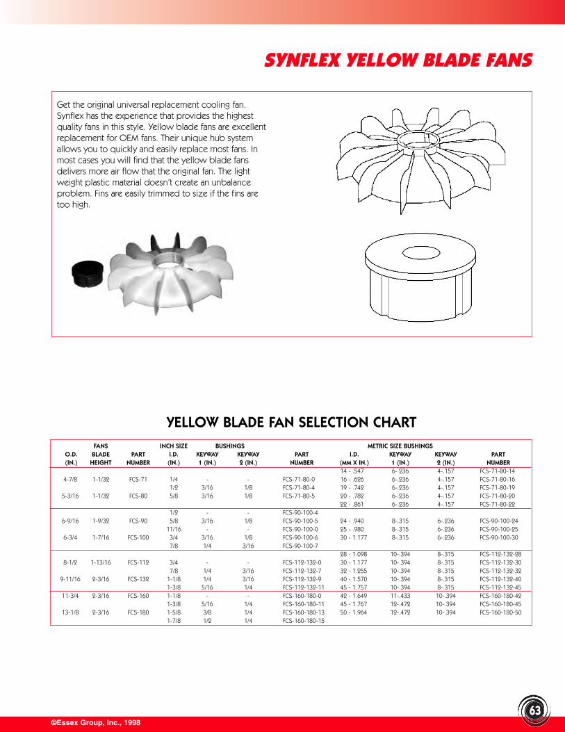
©Essex Group, Inc., 1998
SYNFLEX YELLOW BLADE FANS
63
Get the original universal replacement cooling fan.Synflex has the experience that provides the highestquality fans in this style. Yellow blade fans are excellentreplacement for OEM fans. Their unique hub systemallows you to quickly and easily replace most fans. Inmost cases you will find that the yellow blade fansdelivers more air flow that the original fan. The lightweight plastic material doesn’t create an unbalanceproblem. Fins are easily trimmed to size if the fins aretoo high.
YELLOW BLADE FAN SELECTION CHARTFANS INCH SIZE BUSHINGS METRIC SIZE BUSHINGS
O.D. BLADE PART I.D. KEYWAY KEYWAY PART I.D. KEYWAY KEYWAY PART(IN.) HEIGHT NUMBER (IN.) 1 (IN.) 2 (IN.) NUMBER (MM X IN.) 1 (IN.) 2 (IN.) NUMBER
14 - .547 6- 236 4-.157 FCS-71-80-144-7/8 1-1/32 FCS-71 1/4 - - FCS-71-80-0 16 - .626 6-.236 4-.157 FCS-71-80-16
1/2 3/16 1/8 FCS-71-80-4 19 - .742 6-.236 4-.157 FCS-71-80-195-3/16 1-1/32 FCS-80 5/8 3/16 1/8 FCS-71-80-5 20 - .782 6-.236 4-.157 FCS-71-80-20
22 - .861 6-.236 4-.157 FCS-71-80-221/2 - - FCS-90-100-4
6-9/16 1-9/32 FCS-90 5/8 3/16 1/8 FCS-90-100-5 24 - .940 8-.315 6-.236 FCS-90-100-2411/16 - - FCS-90-100-0 25 - .980 8-.315 6-.236 FCS-90-100-25
6-3/4 1-7/16 FCS-100 3/4 3/16 1/8 FCS-90-100-6 30 - 1.177 8-.315 6-.236 FCS-90-100-307/8 1/4 3/16 FCS-90-100-7
28 - 1.098 10-.394 8-.315 FCS-112-132-288-1/2 1-13/16 FCS-112 3/4 - - FCS-112-132-0 30 - 1.177 10-.394 8-.315 FCS-112-132-30
7/8 1/4 3/16 FCS-112-132-7 32 - 1.255 10-.394 8-.315 FCS-112-132-329-11/16 2-3/16 FCS-132 1-1/8 1/4 3/16 FCS-112-132-9 40 - 1.570 10-.394 8-.315 FCS-112-132-40
1-3/8 5/16 1/4 FCS-112-132-11 45 - 1.757 10-.394 8-.315 FCS-112-132-4511-3/4 2-3/16 FCS-160 1-1/8 - - FCS-160-180-0 42 - 1.649 11-.433 10-.394 FCS-160-180-42
1-3/8 5/16 1/4 FCS-160-180-11 45 - 1.767 12-.472 10-.394 FCS-160-180-4513-1/8 2-3/16 FCS-180 1-5/8 3/8 1/4 FCS-160-180-13 50 - 1.964 12-.472 10-.394 FCS-160-180-50
1-7/8 1/2 1/4 FCS-160-180-15
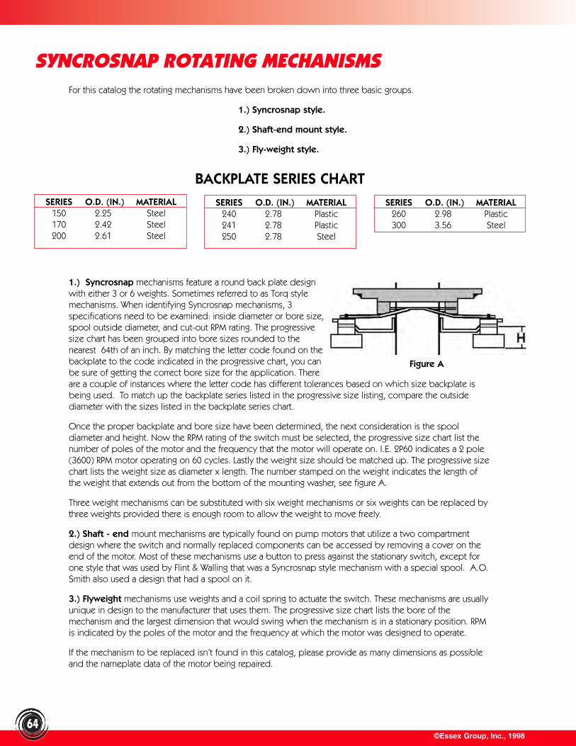
©Essex Group, Inc., 1998
SYNCROSNAP ROTATING MECHANISMS
64
For this catalog the rotating mechanisms have been broken down into three basic groups.
1.) Syncrosnap style.
2.) Shaft-end mount style.
3.) Fly-weight style.
1.) Syncrosnap mechanisms feature a round back plate designwith either 3 or 6 weights. Sometimes referred to as Torq stylemechanisms. When identifying Syncrosnap mechanisms, 3specifications need to be examined: inside diameter or bore size,spool outside diameter, and cut-out RPM rating. The progressivesize chart has been grouped into bore sizes rounded to thenearest 64th of an inch. By matching the letter code found on thebackplate to the code indicated in the progressive chart, you canbe sure of getting the correct bore size for the application. Thereare a couple of instances where the letter code has different tolerances based on which size backplate isbeing used. To match up the backplate series listed in the progressive size listing, compare the outsidediameter with the sizes listed in the backplate series chart.
Once the proper backplate and bore size have been determined, the next consideration is the spooldiameter and height. Now the RPM rating of the switch must be selected, the progressive size chart list thenumber of poles of the motor and the frequency that the motor will operate on. I.E. 2P60 indicates a 2 pole(3600) RPM motor operating on 60 cycles. Lastly the weight size should be matched up. The progressive sizechart lists the weight size as diameter x length. The number stamped on the weight indicates the length ofthe weight that extends out from the bottom of the mounting washer, see figure A.
Three weight mechanisms can be substituted with six weight mechanisms or six weights can be replaced bythree weights provided there is enough room to allow the weight to move freely.
2.) Shaft - end mount mechanisms are typically found on pump motors that utilize a two compartmentdesign where the switch and normally replaced components can be accessed by removing a cover on theend of the motor. Most of these mechanisms use a button to press against the stationary switch, except forone style that was used by Flint & Walling that was a Syncrosnap style mechanism with a special spool. A.O.Smith also used a design that had a spool on it.
3.) Flyweight mechanisms use weights and a coil spring to actuate the switch. These mechanisms are usuallyunique in design to the manufacturer that uses them. The progressive size chart lists the bore of themechanism and the largest dimension that would swing when the mechanism is in a stationary position. RPMis indicated by the poles of the motor and the frequency at which the motor was designed to operate.
If the mechanism to be replaced isn’t found in this catalog, please provide as many dimensions as possibleand the nameplate data of the motor being repaired.
SERIES O.D. (IN.) MATERIAL150 2.25 Steel170 2.42 Steel200 2.61 Steel
SERIES O.D. (IN.) MATERIAL240 2.78 Plastic241 2.78 Plastic250 2.78 Steel
SERIES O.D. (IN.) MATERIAL260 2.98 Plastic300 3.56 Steel
BACKPLATE SERIES CHART
Figure A
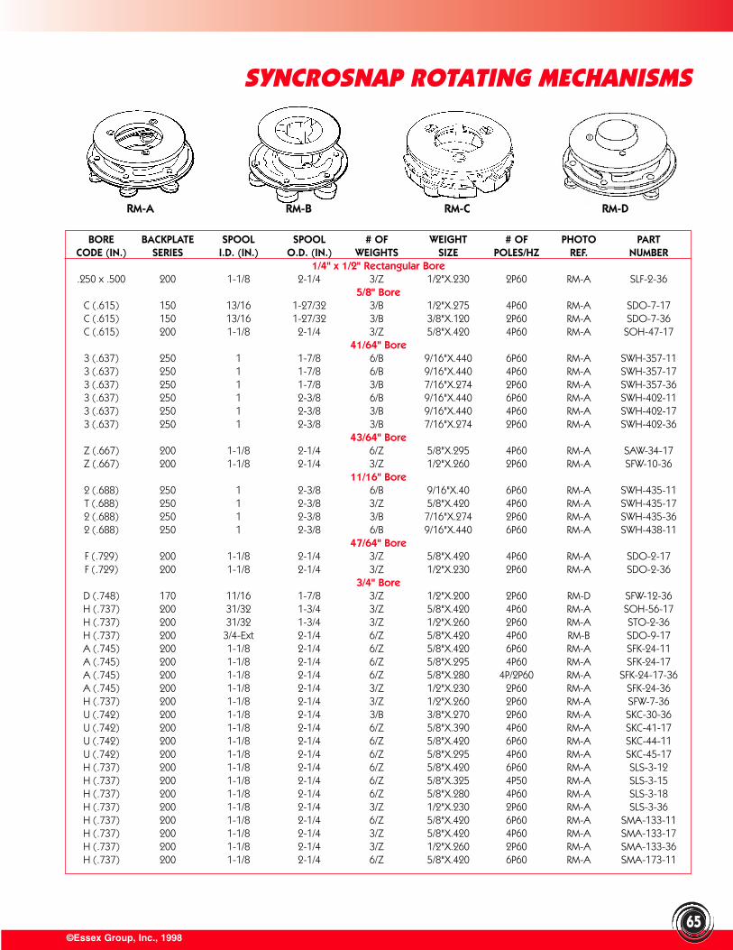
©Essex Group, Inc., 199865
SYNCROSNAP ROTATING MECHANISMS
BORE BACKPLATE SPOOL SPOOL # OF WEIGHT # OF PHOTO PARTCODE (IN.) SERIES I.D. (IN.) O.D. (IN.) WEIGHTS SIZE POLES/HZ REF. NUMBER
1/4" x 1/2" Rectangular Bore.250 x .500 200 1-1/8 2-1/4 3/Z 1/2"X.230 2P60 RM-A SLF-2-36
5/8" BoreC (.615) 150 13/16 1-27/32 3/B 1/2"X.275 4P60 RM-A SDO-7-17C (.615) 150 13/16 1-27/32 3/B 3/8"X.120 2P60 RM-A SDO-7-36C (.615) 200 1-1/8 2-1/4 3/Z 5/8"X.420 4P60 RM-A SOH-47-17
41/64" Bore3 (.637) 250 1 1-7/8 6/B 9/16"X.440 6P60 RM-A SWH-357-113 (.637) 250 1 1-7/8 6/B 9/16"X.440 4P60 RM-A SWH-357-173 (.637) 250 1 1-7/8 3/B 7/16"X.274 2P60 RM-A SWH-357-363 (.637) 250 1 2-3/8 6/B 9/16"X.440 6P60 RM-A SWH-402-113 (.637) 250 1 2-3/8 3/B 9/16"X.440 4P60 RM-A SWH-402-173 (.637) 250 1 2-3/8 3/B 7/16"X.274 2P60 RM-A SWH-402-36
43/64" BoreZ (.667) 200 1-1/8 2-1/4 6/Z 5/8"X.295 4P60 RM-A SAW-34-17Z (.667) 200 1-1/8 2-1/4 3/Z 1/2"X.260 2P60 RM-A SFW-10-36
11/16" Bore2 (.688) 250 1 2-3/8 6/B 9/16"X.40 6P60 RM-A SWH-435-11T (.688) 250 1 2-3/8 3/Z 5/8"X.420 4P60 RM-A SWH-435-172 (.688) 250 1 2-3/8 3/B 7/16"X.274 2P60 RM-A SWH-435-362 (.688) 250 1 2-3/8 6/B 9/16"X.440 6P60 RM-A SWH-438-11
47/64" BoreF (.729) 200 1-1/8 2-1/4 3/Z 5/8"X.420 4P60 RM-A SDO-2-17F (.729) 200 1-1/8 2-1/4 3/Z 1/2"X.230 2P60 RM-A SDO-2-36
3/4" BoreD (.748) 170 11/16 1-7/8 3/Z 1/2"X.200 2P60 RM-D SFW-12-36H (.737) 200 31/32 1-3/4 3/Z 5/8"X.420 4P60 RM-A SOH-56-17H (.737) 200 31/32 1-3/4 3/Z 1/2"X.260 2P60 RM-A STO-2-36H (.737) 200 3/4-Ext 2-1/4 6/Z 5/8"X.420 4P60 RM-B SDO-9-17A (.745) 200 1-1/8 2-1/4 6/Z 5/8"X.420 6P60 RM-A SFK-24-11A (.745) 200 1-1/8 2-1/4 6/Z 5/8"X.295 4P60 RM-A SFK-24-17A (.745) 200 1-1/8 2-1/4 6/Z 5/8"X.280 4P/2P60 RM-A SFK-24-17-36A (.745) 200 1-1/8 2-1/4 3/Z 1/2"X.230 2P60 RM-A SFK-24-36H (.737) 200 1-1/8 2-1/4 3/Z 1/2"X.260 2P60 RM-A SFW-7-36U (.742) 200 1-1/8 2-1/4 3/B 3/8"X.270 2P60 RM-A SKC-30-36U (.742) 200 1-1/8 2-1/4 6/Z 5/8"X.390 4P60 RM-A SKC-41-17U (.742) 200 1-1/8 2-1/4 6/Z 5/8"X.420 6P60 RM-A SKC-44-11U (.742) 200 1-1/8 2-1/4 6/Z 5/8"X.295 4P60 RM-A SKC-45-17H (.737) 200 1-1/8 2-1/4 6/Z 5/8"X.420 6P60 RM-A SLS-3-12H (.737) 200 1-1/8 2-1/4 6/Z 5/8"X.325 4P50 RM-A SLS-3-15H (.737) 200 1-1/8 2-1/4 6/Z 5/8"X.280 4P60 RM-A SLS-3-18H (.737) 200 1-1/8 2-1/4 3/Z 1/2"X.230 2P60 RM-A SLS-3-36H (.737) 200 1-1/8 2-1/4 6/Z 5/8"X.420 6P60 RM-A SMA-133-11H (.737) 200 1-1/8 2-1/4 3/Z 5/8"X.420 4P60 RM-A SMA-133-17H (.737) 200 1-1/8 2-1/4 3/Z 1/2"X.260 2P60 RM-A SMA-133-36H (.737) 200 1-1/8 2-1/4 6/Z 5/8"X.420 6P60 RM-A SMA-173-11
RM-A RM-B RM-C RM-D
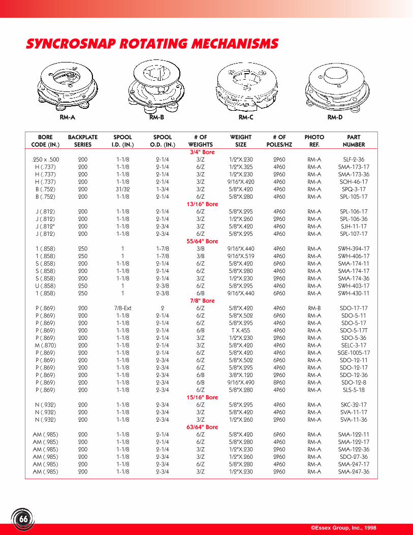
©Essex Group, Inc., 199866
SYNCROSNAP ROTATING MECHANISMS
RM-A RM-B RM-C RM-D
BORE BACKPLATE SPOOL SPOOL # OF WEIGHT # OF PHOTO PARTCODE (IN.) SERIES I.D. (IN.) O.D. (IN.) WEIGHTS SIZE POLES/HZ REF. NUMBER
3/4" Bore.250 x .500 200 1-1/8 2-1/4 3/Z 1/2"X.230 2P60 RM-A SLF-2-36
H (.737) 200 1-1/8 2-1/4 6/Z 1/2"X.325 4P60 RM-A SMA-173-17H (.737) 200 1-1/8 2-1/4 3/Z 1/2"X.230 2P60 RM-A SMA-173-36H (.737) 200 1-1/8 2-1/4 3/Z 9/16"X.420 4P60 RM-A SOH-46-17B (.752) 200 31/32 1-3/4 3/Z 5/8"X.420 4P60 RM-A SPQ-3-17B (.752) 200 1-1/8 2-1/4 6/Z 5/8"X.280 4P60 RM-A SPL-105-17
13/16" BoreJ (.812) 200 1-1/8 2-1/4 6/Z 5/8"X.295 4P60 RM-A SPL-106-17J (.812) 200 1-1/8 2-1/4 3/Z 1/2"X.260 2P60 RM-A SPL-106-36J (.812" 200 1-1/8 2-3/4 3/Z 5/8"X.420 4P60 RM-A SJH-11-17J (.812) 200 1-1/8 2-3/4 6/Z 5/8"X.295 4P60 RM-A SPL-107-17
55/64" Bore1 (.858) 250 1 1-7/8 3/B 9/16"X.440 4P60 RM-A SWH-394-171 (.858) 250 1 1-7/8 3/B 9/16"X.519 4P60 RM-A SWH-406-17S (.858) 200 1-1/8 2-1/4 6/Z 5/8"X.420 6P60 RM-A SMA-174-11S (.858) 200 1-1/8 2-1/4 6/Z 5/8"X.280 4P60 RM-A SMA-174-17S (.858) 200 1-1/8 2-1/4 3/Z 1/2"X.230 2P60 RM-A SMA-174-36U (.858) 250 1 2-3/8 6/Z 5/8"X.295 4P60 RM-A SWH-403-171 (.858) 250 1 2-3/8 6/B 9/16"X.440 6P60 RM-A SWH-430-11
7/8" BoreP (.869) 200 7/8-Ext 2 6/Z 5/8"X.420 4P60 RM-B SDO-17-17P (.869) 200 1-1/8 2-1/4 6/Z 5/8"X.502 6P60 RM-A SDO-5-11P (.869) 200 1-1/8 2-1/4 6/Z 5/8"X.295 4P60 RM-A SDO-5-17P (.869) 200 1-1/8 2-1/4 6/B T X.455 4P60 RM-A SDO-5-17TP (.869) 200 1-1/8 2-1/4 3/Z 1/2"X.230 2P60 RM-A SDO-5-36M (.870) 200 1-1/8 2-1/4 3/Z 5/8"X.420 4P60 RM-A SELC-3-17P (.869) 200 1-1/8 2-1/4 6/Z 5/8"X.420 4P60 RM-A SGE-1005-17P (.869) 200 1-1/8 2-3/4 6/Z 5/8"X.502 6P60 RM-A SDO-12-11P (.869) 200 1-1/8 2-3/4 6/Z 5/8"X.295 4P60 RM-A SDO-12-17P (.869) 200 1-1/8 2-3/4 6/B 3/8"X.120 2P60 RM-A SDO-12-36P (.869) 200 1-1/8 2-3/4 6/B 9/16"X.490 8P60 RM-A SDO-12-8P (.869) 200 1-1/8 2-3/4 6/Z 5/8"X.280 4P60 RM-A SLS-5-18
15/16" BoreN (.932) 200 1-1/8 2-3/4 6/Z 5/8"X.295 4P60 RM-A SKC-32-17N (.932) 200 1-1/8 2-3/4 3/Z 5/8"X.420 4P60 RM-A SVA-11-17N (.932) 200 1-1/8 2-3/4 3/Z 1/2"X.260 2P60 RM-A SVA-11-36
63/64" BoreAM (.985) 200 1-1/8 2-1/4 6/Z 5/8"X.420 6P60 RM-A SMA-122-11AM (.985) 200 1-1/8 2-1/4 6/Z 5/8"X.280 4P60 RM-A SMA-122-17AM (.985) 200 1-1/8 2-1/4 3/Z 1/2"X.230 2P60 RM-A SMA-122-36AM (.985) 200 1-1/8 2-3/4 3/Z 1/2"X.260 2P60 RM-A SDO-27-36AM (.985) 200 1-1/8 2-3/4 6/Z 5/8"X.280 4P60 RM-A SMA-247-17AM (.985) 200 1-1/8 2-3/4 3/Z 1/2"X.230 2P60 RM-A SMA-247-36
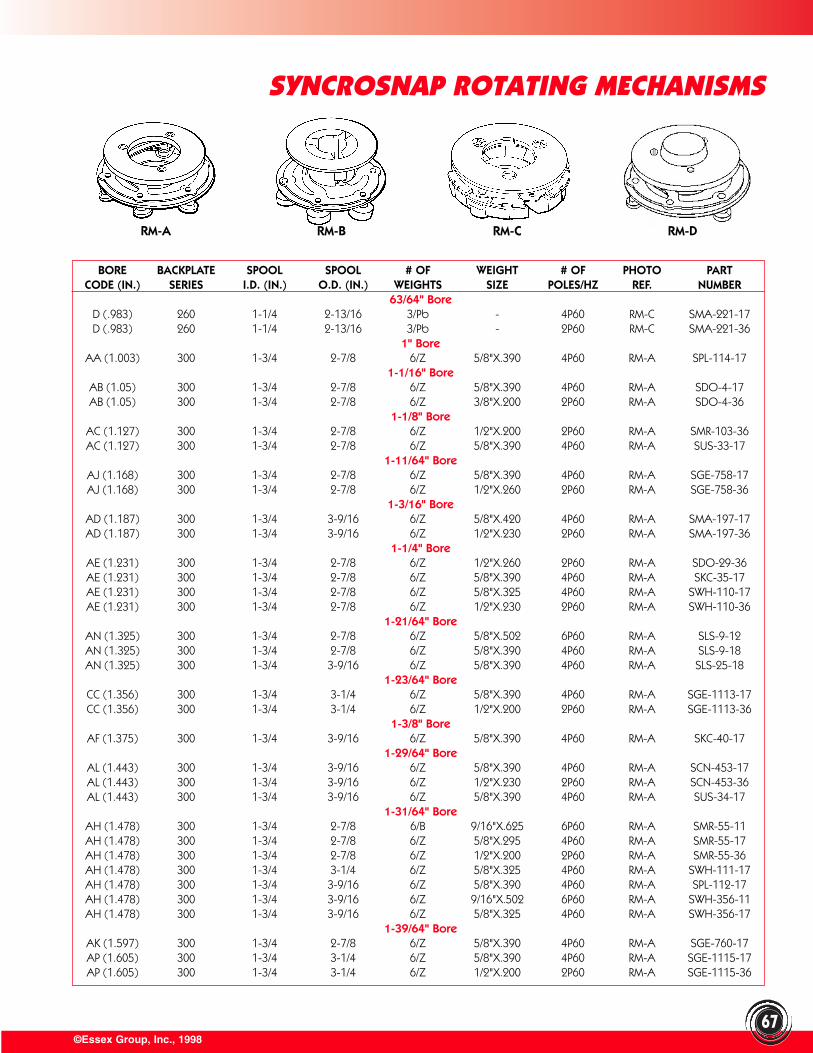
©Essex Group, Inc., 1998
SYNCROSNAP ROTATING MECHANISMS
67
BORE BACKPLATE SPOOL SPOOL # OF WEIGHT # OF PHOTO PARTCODE (IN.) SERIES I.D. (IN.) O.D. (IN.) WEIGHTS SIZE POLES/HZ REF. NUMBER
63/64" BoreD (.983) 260 1-1/4 2-13/16 3/Pb - 4P60 RM-C SMA-221-17D (.983) 260 1-1/4 2-13/16 3/Pb - 2P60 RM-C SMA-221-36
1" BoreAA (1.003) 300 1-3/4 2-7/8 6/Z 5/8"X.390 4P60 RM-A SPL-114-17
1-1/16" BoreAB (1.05) 300 1-3/4 2-7/8 6/Z 5/8"X.390 4P60 RM-A SDO-4-17AB (1.05) 300 1-3/4 2-7/8 6/Z 3/8"X.200 2P60 RM-A SDO-4-36
1-1/8" BoreAC (1.127) 300 1-3/4 2-7/8 6/Z 1/2"X.200 2P60 RM-A SMR-103-36AC (1.127) 300 1-3/4 2-7/8 6/Z 5/8"X.390 4P60 RM-A SUS-33-17
1-11/64" BoreAJ (1.168) 300 1-3/4 2-7/8 6/Z 5/8"X.390 4P60 RM-A SGE-758-17AJ (1.168) 300 1-3/4 2-7/8 6/Z 1/2"X.260 2P60 RM-A SGE-758-36
1-3/16" BoreAD (1.187) 300 1-3/4 3-9/16 6/Z 5/8"X.420 4P60 RM-A SMA-197-17AD (1.187) 300 1-3/4 3-9/16 6/Z 1/2"X.230 2P60 RM-A SMA-197-36
1-1/4" BoreAE (1.231) 300 1-3/4 2-7/8 6/Z 1/2"X.260 2P60 RM-A SDO-29-36AE (1.231) 300 1-3/4 2-7/8 6/Z 5/8"X.390 4P60 RM-A SKC-35-17AE (1.231) 300 1-3/4 2-7/8 6/Z 5/8"X.325 4P60 RM-A SWH-110-17AE (1.231) 300 1-3/4 2-7/8 6/Z 1/2"X.230 2P60 RM-A SWH-110-36
1-21/64" BoreAN (1.325) 300 1-3/4 2-7/8 6/Z 5/8"X.502 6P60 RM-A SLS-9-12AN (1.325) 300 1-3/4 2-7/8 6/Z 5/8"X.390 4P60 RM-A SLS-9-18AN (1.325) 300 1-3/4 3-9/16 6/Z 5/8"X.390 4P60 RM-A SLS-25-18
1-23/64" BoreCC (1.356) 300 1-3/4 3-1/4 6/Z 5/8"X.390 4P60 RM-A SGE-1113-17CC (1.356) 300 1-3/4 3-1/4 6/Z 1/2"X.200 2P60 RM-A SGE-1113-36
1-3/8" BoreAF (1.375) 300 1-3/4 3-9/16 6/Z 5/8"X.390 4P60 RM-A SKC-40-17
1-29/64" BoreAL (1.443) 300 1-3/4 3-9/16 6/Z 5/8"X.390 4P60 RM-A SCN-453-17AL (1.443) 300 1-3/4 3-9/16 6/Z 1/2"X.230 2P60 RM-A SCN-453-36AL (1.443) 300 1-3/4 3-9/16 6/Z 5/8"X.390 4P60 RM-A SUS-34-17
1-31/64" BoreAH (1.478) 300 1-3/4 2-7/8 6/B 9/16"X.625 6P60 RM-A SMR-55-11AH (1.478) 300 1-3/4 2-7/8 6/Z 5/8"X.295 4P60 RM-A SMR-55-17AH (1.478) 300 1-3/4 2-7/8 6/Z 1/2"X.200 2P60 RM-A SMR-55-36AH (1.478) 300 1-3/4 3-1/4 6/Z 5/8"X.325 4P60 RM-A SWH-111-17AH (1.478) 300 1-3/4 3-9/16 6/Z 5/8"X.390 4P60 RM-A SPL-112-17AH (1.478) 300 1-3/4 3-9/16 6/Z 9/16"X.502 6P60 RM-A SWH-356-11AH (1.478) 300 1-3/4 3-9/16 6/Z 5/8"X.325 4P60 RM-A SWH-356-17
1-39/64" BoreAK (1.597) 300 1-3/4 2-7/8 6/Z 5/8"X.390 4P60 RM-A SGE-760-17AP (1.605) 300 1-3/4 3-1/4 6/Z 5/8"X.390 4P60 RM-A SGE-1115-17AP (1.605) 300 1-3/4 3-1/4 6/Z 1/2"X.200 2P60 RM-A SGE-1115-36
RM-A RM-B RM-C RM-D
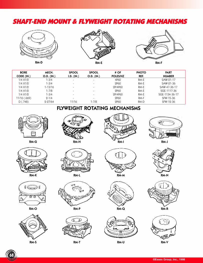
©Essex Group, Inc., 199868
SHAFT-END MOUNT & FLYWEIGHT ROTATING MECHANISMS
BORE MECH. SPOOL SPOOL # OF PHOTO PARTCODE (IN.) O.D. (IN.) I.D. (IN.) O.D. (IN.) POLES/HZ REF. NUMBER
1/4 X1/2 1-3/4 - - 4P60 RM-E SAW-21-171/4 X1/2 1-3/4 - - 2P60 RM-E SAW-21-361/4 X1/2 1-13/16 - - 2P/4P60 RM-E SAW-47-36-171/4 X1/2 1-7/8 - - 2P60 RM-E SGE-1117-361/4 X1/2 1-3/4 - - 2P/4P60 RM-E SGE-1134-36-17
11/16 (.669) 2-1/4 - - 2P60 RM-F SFW-15-36D (.748) 2-27/64 11/16 1-7/8 2P60 RM-D SFW-12-36
FLYWEIGHT ROTATING MECHANISMS
RM-D RM-E RM-F
RM-G RM-H RM-I RM-J
RM-K RM-L RM-M RM-N
RM-O RM-P RM-Q RM-R
RM-S RM-T RM-U RM-V
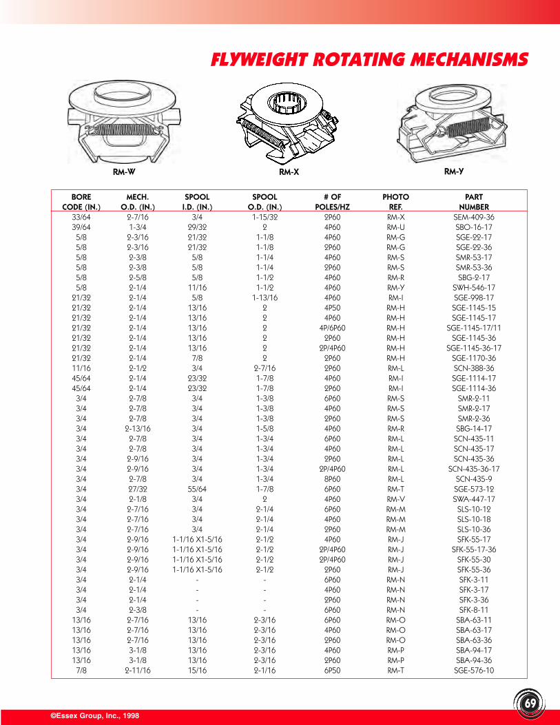
©Essex Group, Inc., 1998
FLYWEIGHT ROTATING MECHANISMS
69
BORE MECH. SPOOL SPOOL # OF PHOTO PARTCODE (IN.) O.D. (IN.) I.D. (IN.) O.D. (IN.) POLES/HZ REF. NUMBER
33/64 2-7/16 3/4 1-15/32 2P60 RM-X SEM-409-3639/64 1-3/4 29/32 2 4P60 RM-U SBO-16-175/8 2-3/16 21/32 1-1/8 4P60 RM-G SGE-22-175/8 2-3/16 21/32 1-1/8 2P60 RM-G SGE-22-365/8 2-3/8 5/8 1-1/4 4P60 RM-S SMR-53-175/8 2-3/8 5/8 1-1/4 2P60 RM-S SMR-53-365/8 2-5/8 5/8 1-1/2 4P60 RM-R SBG-2-175/8 2-1/4 11/16 1-1/2 4P60 RM-Y SWH-546-17
21/32 2-1/4 5/8 1-13/16 4P60 RM-I SGE-998-1721/32 2-1/4 13/16 2 4P50 RM-H SGE-1145-1521/32 2-1/4 13/16 2 4P60 RM-H SGE-1145-1721/32 2-1/4 13/16 2 4P/6P60 RM-H SGE-1145-17/1121/32 2-1/4 13/16 2 2P60 RM-H SGE-1145-3621/32 2-1/4 13/16 2 2P/4P60 RM-H SGE-1145-36-1721/32 2-1/4 7/8 2 2P60 RM-H SGE-1170-3611/16 2-1/2 3/4 2-7/16 2P60 RM-L SCN-388-3645/64 2-1/4 23/32 1-7/8 4P60 RM-I SGE-1114-1745/64 2-1/4 23/32 1-7/8 2P60 RM-I SGE-1114-363/4 2-7/8 3/4 1-3/8 6P60 RM-S SMR-2-113/4 2-7/8 3/4 1-3/8 4P60 RM-S SMR-2-173/4 2-7/8 3/4 1-3/8 2P60 RM-S SMR-2-363/4 2-13/16 3/4 1-5/8 4P60 RM-R SBG-14-173/4 2-7/8 3/4 1-3/4 6P60 RM-L SCN-435-113/4 2-7/8 3/4 1-3/4 4P60 RM-L SCN-435-173/4 2-9/16 3/4 1-3/4 2P60 RM-L SCN-435-363/4 2-9/16 3/4 1-3/4 2P/4P60 RM-L SCN-435-36-173/4 2-7/8 3/4 1-3/4 8P60 RM-L SCN-435-93/4 27/32 55/64 1-7/8 6P60 RM-T SGE-573-123/4 2-1/8 3/4 2 4P60 RM-V SWA-447-173/4 2-7/16 3/4 2-1/4 6P60 RM-M SLS-10-123/4 2-7/16 3/4 2-1/4 4P60 RM-M SLS-10-183/4 2-7/16 3/4 2-1/4 2P60 RM-M SLS-10-363/4 2-9/16 1-1/16 X1-5/16 2-1/2 4P60 RM-J SFK-55-173/4 2-9/16 1-1/16 X1-5/16 2-1/2 2P/4P60 RM-J SFK-55-17-363/4 2-9/16 1-1/16 X1-5/16 2-1/2 2P/4P60 RM-J SFK-55-303/4 2-9/16 1-1/16 X1-5/16 2-1/2 2P60 RM-J SFK-55-363/4 2-1/4 - - 6P60 RM-N SFK-3-113/4 2-1/4 - - 4P60 RM-N SFK-3-173/4 2-1/4 - - 2P60 RM-N SFK-3-363/4 2-3/8 - - 6P60 RM-N SFK-8-11
13/16 2-7/16 13/16 2-3/16 6P60 RM-O SBA-63-1113/16 2-7/16 13/16 2-3/16 4P60 RM-O SBA-63-1713/16 2-7/16 13/16 2-3/16 2P60 RM-O SBA-63-3613/16 3-1/8 13/16 2-3/16 4P60 RM-P SBA-94-1713/16 3-1/8 13/16 2-3/16 2P60 RM-P SBA-94-367/8 2-11/16 15/16 2-1/16 6P50 RM-T SGE-576-10
RM-W RM-X RM-Y
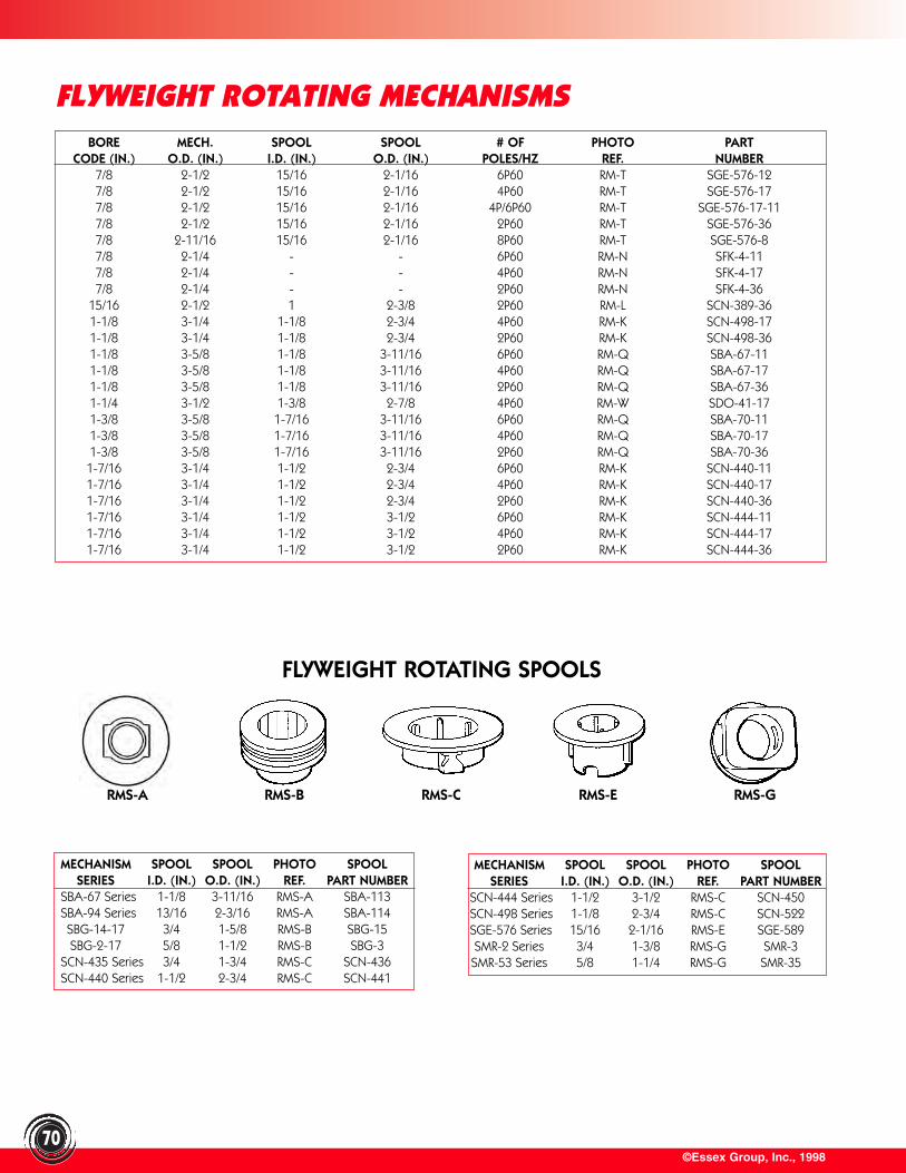
©Essex Group, Inc., 199870
FLYWEIGHT ROTATING MECHANISMSBORE MECH. SPOOL SPOOL # OF PHOTO PART
CODE (IN.) O.D. (IN.) I.D. (IN.) O.D. (IN.) POLES/HZ REF. NUMBER7/8 2-1/2 15/16 2-1/16 6P60 RM-T SGE-576-127/8 2-1/2 15/16 2-1/16 4P60 RM-T SGE-576-177/8 2-1/2 15/16 2-1/16 4P/6P60 RM-T SGE-576-17-117/8 2-1/2 15/16 2-1/16 2P60 RM-T SGE-576-367/8 2-11/16 15/16 2-1/16 8P60 RM-T SGE-576-87/8 2-1/4 - - 6P60 RM-N SFK-4-117/8 2-1/4 - - 4P60 RM-N SFK-4-177/8 2-1/4 - - 2P60 RM-N SFK-4-36
15/16 2-1/2 1 2-3/8 2P60 RM-L SCN-389-361-1/8 3-1/4 1-1/8 2-3/4 4P60 RM-K SCN-498-171-1/8 3-1/4 1-1/8 2-3/4 2P60 RM-K SCN-498-361-1/8 3-5/8 1-1/8 3-11/16 6P60 RM-Q SBA-67-111-1/8 3-5/8 1-1/8 3-11/16 4P60 RM-Q SBA-67-171-1/8 3-5/8 1-1/8 3-11/16 2P60 RM-Q SBA-67-361-1/4 3-1/2 1-3/8 2-7/8 4P60 RM-W SDO-41-171-3/8 3-5/8 1-7/16 3-11/16 6P60 RM-Q SBA-70-111-3/8 3-5/8 1-7/16 3-11/16 4P60 RM-Q SBA-70-171-3/8 3-5/8 1-7/16 3-11/16 2P60 RM-Q SBA-70-361-7/16 3-1/4 1-1/2 2-3/4 6P60 RM-K SCN-440-111-7/16 3-1/4 1-1/2 2-3/4 4P60 RM-K SCN-440-171-7/16 3-1/4 1-1/2 2-3/4 2P60 RM-K SCN-440-361-7/16 3-1/4 1-1/2 3-1/2 6P60 RM-K SCN-444-111-7/16 3-1/4 1-1/2 3-1/2 4P60 RM-K SCN-444-171-7/16 3-1/4 1-1/2 3-1/2 2P60 RM-K SCN-444-36
MECHANISM SPOOL SPOOL PHOTO SPOOLSERIES I.D. (IN.) O.D. (IN.) REF. PART NUMBER
SBA-67 Series 1-1/8 3-11/16 RMS-A SBA-113SBA-94 Series 13/16 2-3/16 RMS-A SBA-114SBG-14-17 3/4 1-5/8 RMS-B SBG-15SBG-2-17 5/8 1-1/2 RMS-B SBG-3
SCN-435 Series 3/4 1-3/4 RMS-C SCN-436SCN-440 Series 1-1/2 2-3/4 RMS-C SCN-441
MECHANISM SPOOL SPOOL PHOTO SPOOLSERIES I.D. (IN.) O.D. (IN.) REF. PART NUMBER
SCN-444 Series 1-1/2 3-1/2 RMS-C SCN-450SCN-498 Series 1-1/8 2-3/4 RMS-C SCN-522SGE-576 Series 15/16 2-1/16 RMS-E SGE-589SMR-2 Series 3/4 1-3/8 RMS-G SMR-3SMR-53 Series 5/8 1-1/4 RMS-G SMR-35
FLYWEIGHT ROTATING SPOOLS
RMS-A RMS-B RMS-C RMS-E RMS-G
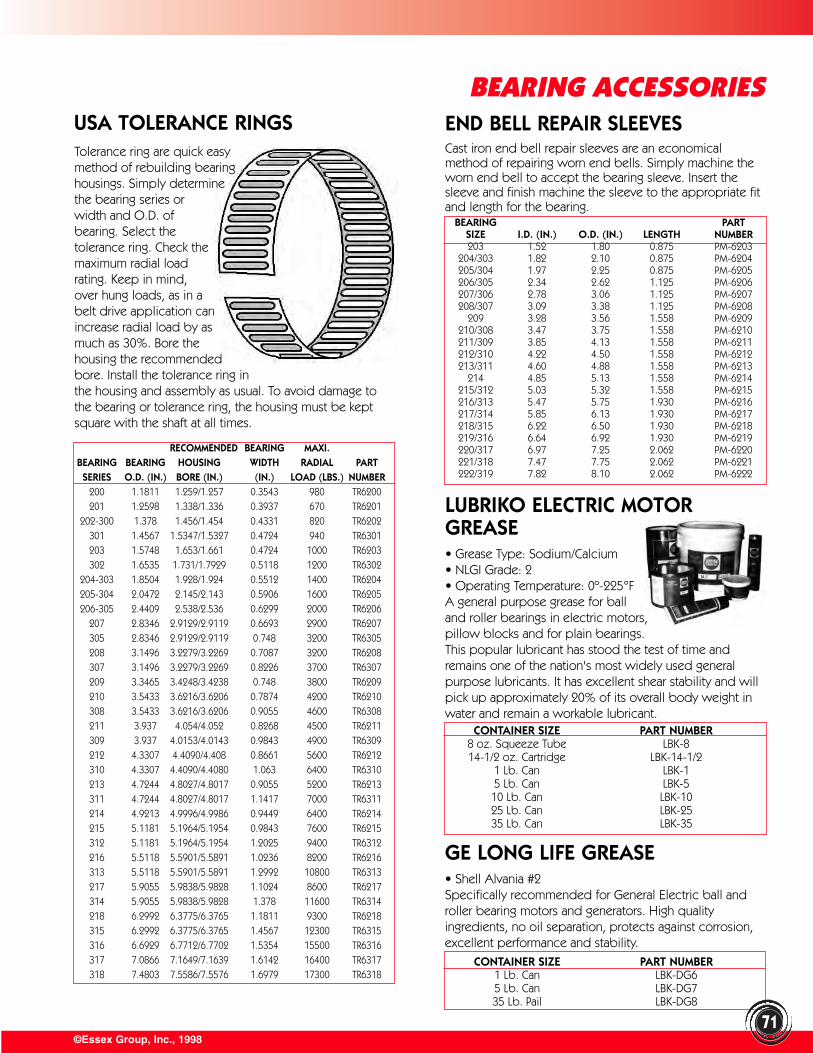
CONTAINER SIZE PART NUMBER1 Lb. Can LBK-DG65 Lb. Can LBK-DG735 Lb. Pail LBK-DG8
©Essex Group, Inc., 199871
BEARING ACCESSORIESUSA TOLERANCE RINGSTolerance ring are quick easy method of rebuilding bearing housings. Simply determine the bearing series or width and O.D. of bearing. Select the tolerance ring. Check the maximum radial load rating. Keep in mind, over hung loads, as in a belt drive application can increase radial load by as much as 30%. Bore the housing the recommended bore. Install the tolerance ring in the housing and assembly as usual. To avoid damage tothe bearing or tolerance ring, the housing must be keptsquare with the shaft at all times.
RECOMMENDED BEARING MAXI.BEARING BEARING HOUSING WIDTH RADIAL PARTSERIES O.D. (IN.) BORE (IN.) (IN.) LOAD (LBS.) NUMBER
200 1.1811 1.259/1.257 0.3543 980 TR6200201 1.2598 1.338/1.336 0.3937 670 TR6201
202-300 1.378 1.456/1.454 0.4331 820 TR6202301 1.4567 1.5347/1.5327 0.4724 940 TR6301203 1.5748 1.653/1.661 0.4724 1000 TR6203302 1.6535 1.731/1.7929 0.5118 1200 TR6302
204-303 1.8504 1.928/1.924 0.5512 1400 TR6204205-304 2.0472 2.145/2.143 0.5906 1600 TR6205206-305 2.4409 2.538/2.536 0.6299 2000 TR6206
207 2.8346 2.9129/2.9119 0.6693 2900 TR6207305 2.8346 2.9129/2.9119 0.748 3200 TR6305208 3.1496 3.2279/3.2269 0.7087 3200 TR6208307 3.1496 3.2279/3.2269 0.8226 3700 TR6307209 3.3465 3.4248/3.4238 0.748 3800 TR6209210 3.5433 3.6216/3.6206 0.7874 4200 TR6210308 3.5433 3.6216/3.6206 0.9055 4600 TR6308211 3.937 4.054/4.052 0.8268 4500 TR6211309 3.937 4.0153/4.0143 0.9843 4900 TR6309212 4.3307 4.4090/4.408 0.8661 5600 TR6212310 4.3307 4.4090/4.4080 1.063 6400 TR6310213 4.7244 4.8027/4.8017 0.9055 5200 TR6213311 4.7244 4.8027/4.8017 1.1417 7000 TR6311214 4.9213 4.9996/4.9986 0.9449 6400 TR6214215 5.1181 5.1964/5.1954 0.9843 7600 TR6215312 5.1181 5.1964/5.1954 1.2025 9400 TR6312216 5.5118 5.5901/5.5891 1.0236 8200 TR6216313 5.5118 5.5901/5.5891 1.2992 10800 TR6313217 5.9055 5.9838/5.9828 1.1024 8600 TR6217314 5.9055 5.9838/5.9828 1.378 11600 TR6314218 6.2992 6.3775/6.3765 1.1811 9300 TR6218315 6.2992 6.3775/6.3765 1.4567 12300 TR6315316 6.6929 6.7712/6.7702 1.5354 15500 TR6316317 7.0866 7.1649/7.1639 1.6142 16400 TR6317318 7.4803 7.5586/7.5576 1.6979 17300 TR6318
END BELL REPAIR SLEEVESCast iron end bell repair sleeves are an economicalmethod of repairing worn end bells. Simply machine theworn end bell to accept the bearing sleeve. Insert thesleeve and finish machine the sleeve to the appropriate fitand length for the bearing.
BEARING PARTSIZE I.D. (IN.) O.D. (IN.) LENGTH NUMBER203 1.52 1.80 0.875 PM-6203
204/303 1.82 2.10 0.875 PM-6204205/304 1.97 2.25 0.875 PM-6205206/305 2.34 2.62 1.125 PM-6206207/306 2.78 3.06 1.125 PM-6207208/307 3.09 3.38 1.125 PM-6208
209 3.28 3.56 1.558 PM-6209210/308 3.47 3.75 1.558 PM-6210211/309 3.85 4.13 1.558 PM-6211212/310 4.22 4.50 1.558 PM-6212213/311 4.60 4.88 1.558 PM-6213
214 4.85 5.13 1.558 PM-6214215/312 5.03 5.32 1.558 PM-6215216/313 5.47 5.75 1.930 PM-6216217/314 5.85 6.13 1.930 PM-6217218/315 6.22 6.50 1.930 PM-6218219/316 6.64 6.92 1.930 PM-6219220/317 6.97 7.25 2.062 PM-6220221/318 7.47 7.75 2.062 PM-6221222/319 7.82 8.10 2.062 PM-6222
CONTAINER SIZE PART NUMBER8 oz. Squeeze Tube LBK-814-1/2 oz. Cartridge LBK-14-1/2
1 Lb. Can LBK-15 Lb. Can LBK-510 Lb. Can LBK-1025 Lb. Can LBK-2535 Lb. Can LBK-35
GE LONG LIFE GREASE• Shell Alvania #2Specifically recommended for General Electric ball androller bearing motors and generators. High qualityingredients, no oil separation, protects against corrosion,excellent performance and stability.
LUBRIKO ELECTRIC MOTORGREASE• Grease Type: Sodium/Calcium• NLGI Grade: 2• Operating Temperature: 0º-225°FA general purpose grease for ball and roller bearings in electric motors, pillow blocks and for plain bearings. This popular lubricant has stood the test of time andremains one of the nation's most widely used generalpurpose lubricants. It has excellent shear stability and willpick up approximately 20% of its overall body weight inwater and remain a workable lubricant.
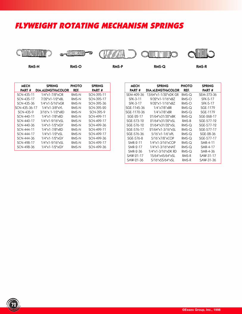
©Essex Group, Inc., 1998
FLYWEIGHT ROTATING MECHANISM SPRINGS
72
MECH SPRING PHOTO SPRINGPART # DIA.xLENGTHxCOLOR REF. PART #
SCN-435-11 1/4"x1-7/8"xOR RMS-N SCN-395-11SCN-435-17 7/32"x1-1/2"xBL RMS-N SCN-395-17SCN-435-36 1/4"x1-5/16"xGR RMS-N SCN-395-36
SCN-435-36-17 1/4"x1-3/8"xYL RMS-N SCN-395-20SCN-435-9 3/16"x 1-1/2"xRD RMS-N SCN-395-9SCN-440-11 1/4"x1-7/8"xRD RMS-N SCN-499-11SCN-440-17 1/4"x1-9/16"xSL RMS-N SCN-499-17SCN-440-36 1/4"x1-1/2"xGY RMS-N SCN-499-36SCN-444-11 1/4"x1-7/8"xRD RMS-N SCN-499-11SCN-444-17 1/4"x1-1/2"xSL RMS-N SCN-499-17SCN-444-36 1/4"x1-1/2"xGY RMS-N SCN-499-36SCN-498-17 1/4"x1-9/16"xSL RMS-N SCN-499-17SCN-498-36 1/4"x1-1/2"xGY RMS-N SCN-499-36
MECH SPRING PHOTO SPRINGPART # DIA.xLENGTHxCOLOR REF. PART #
SEM-409-36 13/64"x1-1/32"xDK GR RMS-Q SEM-373-36SFK-3-11 9/32"x1-1/16"xBZ RMS-O SFK-5-17SFK-3-17 9/32"x1-1/16"xBZ RMS-O SFK-5-17
SGE-1145-36 1/4”x7/8”xBR RMS-Q SGE-1179SGE-1170-36 1/4”x7/8”xBR RMS-Q SGE-1179SGE-22-17 21/64"x31/32"xBK RMS-Q SGE-268-17SGE-573-12 21/64"x31/32"xSL RMS-B SGE-577-12SGE-576-12 21/64"x31/32"xSL RMS-Q SGE-577-12SGE-576-17 21/64"x1-3/16"xSL RMS-Q SGE-577-17SGE-576-36 5/16”x1-1/6”xPL RMS-Q SGE-28-36SGE-576-8 5/16”x7/8”xCOP RMS-Q SGE-577-17SMR-2-11 1/4"x1-3/16"xCOP RMS-Q SMR-4-11SMR-2-17 1/4"x1-3/16"xNAT RMS-Q SMR-4-17SMR-2-36 1/4"x1-3/16"xDK RD RMS-Q SMR-4-36
SAW-21-17 15/64"x45/64"xSL RMS-R SAW-31-17SAW-21-36 5/16"x55/64"xSL RMS-R SAW-31-36
RMS-N RMS-O RMS-P RMS-Q RMS-R
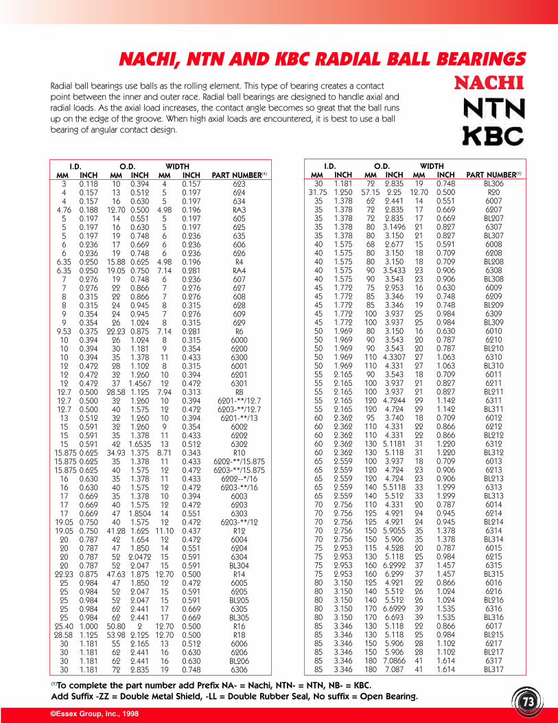
©Essex Group, Inc., 1998
NACHI, NTN AND KBC RADIAL BALL BEARINGS
(1)To complete the part number add Prefix NA- = Nachi, NTN- = NTN, NB- = KBC.Add Suffix -ZZ = Double Metal Shield, -LL = Double Rubber Seal, No suffix = Open Bearing.
Radial ball bearings use balls as the rolling element. This type of bearing creates a contactpoint between the inner and outer race. Radial ball bearings are designed to handle axial andradial loads. As the axial load increases, the contact angle becomes so great that the ball runsup on the edge of the groove. When high axial loads are encountered, it is best to use a ballbearing of angular contact design.
I.D. O.D. WIDTHMM INCH MM INCH MM INCH PART NUMBER(1)
3 0.118 10 0.394 4 0.157 6234 0.157 13 0.512 5 0.197 6244 0.157 16 0.630 5 0.197 634
4.76 0.188 12.70 0.500 4.98 0.196 RA35 0.197 14 0.551 5 0.197 6055 0.197 16 0.630 5 0.197 6255 0.197 19 0.748 6 0.236 6356 0.236 17 0.669 6 0.236 6066 0.236 19 0.748 6 0.236 626
6.35 0.250 15.88 0.625 4.98 0.196 R46.35 0.250 19.05 0.750 7.14 0.281 RA4
7 0.276 19 0.748 6 0.236 6077 0.276 22 0.866 7 0.276 6278 0.315 22 0.866 7 0.276 6088 0.315 24 0.945 8 0.315 6289 0.354 24 0.945 7 0.276 6099 0.354 26 1.024 8 0.315 629
9.53 0.375 22.23 0.875 7.14 0.281 R610 0.394 26 1.024 8 0.315 600010 0.394 30 1.181 9 0.354 620010 0.394 35 1.378 11 0.433 630012 0.472 28 1.102 8 0.315 600112 0.472 32 1.260 10 0.394 620112 0.472 37 1.4567 12 0.472 6301
12.7 0.500 28.58 1.125 7.94 0.313 R812.7 0.500 32 1.260 10 0.394 6201-**/12.712.7 0.500 40 1.575 12 0.472 6203-**/12.713 0.512 32 1.260 10 0.394 6201-**/1315 0.591 32 1.260 9 0.354 600215 0.591 35 1.378 11 0.433 620215 0.591 42 1.6535 13 0.512 6302
15.875 0.625 34.93 1.375 8.71 0.343 R1015.875 0.625 35 1.378 11 0.433 6202-**/15.87515.875 0.625 40 1.575 12 0.472 6203-**/15.875
16 0.630 35 1.378 11 0.433 6202--*/1616 0.630 40 1.575 12 0.472 6203-**/1617 0.669 35 1.378 10 0.394 600317 0.669 40 1.575 12 0.472 620317 0.669 47 1.8504 14 0.551 6303
19.05 0.750 40 1.575 12 0.472 6203-**/1219.05 0.750 41.28 1.625 11.10 0.437 R12
20 0.787 42 1.654 12 0.472 600420 0.787 47 1.850 14 0.551 620420 0.787 52 2.0472 15 0.591 630420 0.787 52 2.047 15 0.591 BL304
22.23 0.875 47.63 1.875 12.70 0.500 R1425 0.984 47 1.850 12 0.472 600525 0.984 52 2.047 15 0.591 620525 0.984 52 2.047 15 0.591 BL20525 0.984 62 2.441 17 0.669 630525 0.984 62 2.441 17 0.669 BL305
25.40 1.000 50.80 2 12.70 0.500 R1628.58 1.125 53.98 2.125 12.70 0.500 R18
30 1.181 55 2.165 13 0.512 600630 1.181 62 2.441 16 0.630 620630 1.181 62 2.441 16 0.630 BL20630 1.181 72 2.835 19 0.748 6306
I.D. O.D. WIDTHMM INCH MM INCH MM INCH PART NUMBER(1)
30 1.181 72 2.835 19 0.748 BL30631.75 1.250 57.15 2.25 12.70 0.500 R20
35 1.378 62 2.441 14 0.551 600735 1.378 72 2.835 17 0.669 620735 1.378 72 2.835 17 0.669 BL20735 1.378 80 3.1496 21 0.827 630735 1.378 80 3.150 21 0.827 BL30740 1.575 68 2.677 15 0.591 600840 1.575 80 3.150 18 0.709 620840 1.575 80 3.150 18 0.709 BL20840 1.575 90 3.5433 23 0.906 630840 1.575 90 3.543 23 0.906 BL30845 1.772 75 2.953 16 0.630 600945 1.772 85 3.346 19 0.748 620945 1.772 85 3.346 19 0.748 BL20945 1.772 100 3.937 25 0.984 630945 1.772 100 3.937 25 0.984 BL30950 1.969 80 3.150 16 0.630 601050 1.969 90 3.543 20 0.787 621050 1.969 90 3.543 20 0.787 BL21050 1.969 110 4.3307 27 1.063 631050 1.969 110 4.331 27 1.063 BL31055 2.165 90 3.543 18 0.709 601155 2.165 100 3.937 21 0.827 621155 2.165 100 3.937 21 0.827 BL21155 2.165 120 4.7244 29 1.142 631155 2.165 120 4.724 29 1.142 BL31160 2.362 95 3.740 18 0.709 601260 2.362 110 4.331 22 0.866 621260 2.362 110 4.331 22 0.866 BL21260 2.362 130 5.1181 31 1.220 631260 2.362 130 5.118 31 1.220 BL31265 2.559 100 3.937 18 0.709 601365 2.559 120 4.724 23 0.906 621365 2.559 120 4.724 23 0.906 BL21365 2.559 140 5.5118 33 1.299 631365 2.559 140 5.512 33 1.299 BL31370 2.756 110 4.331 20 0.787 601470 2.756 125 4.921 24 0.945 621470 2.756 125 4.921 24 0.945 BL21470 2.756 150 5.9055 35 1.378 631470 2.756 150 5.906 35 1.378 BL31475 2.953 115 4.528 20 0.787 601575 2.953 130 5.118 25 0.984 621575 2.953 160 6.2992 37 1.457 631575 2.953 160 6.299 37 1.457 BL31580 3.150 125 4.921 22 0.866 601680 3.150 140 5.512 26 1.024 621680 3.150 140 5.512 26 1.024 BL21680 3.150 170 6.6929 39 1.535 631680 3.150 170 6.693 39 1.535 BL31685 3.346 130 5.118 22 0.866 601785 3.346 130 5.118 25 0.984 BL21585 3.346 150 5.906 28 1.102 621785 3.346 150 5.906 28 1.102 BL21785 3.346 180 7.0866 41 1.614 631785 3.346 180 7.087 41 1.614 BL317
73
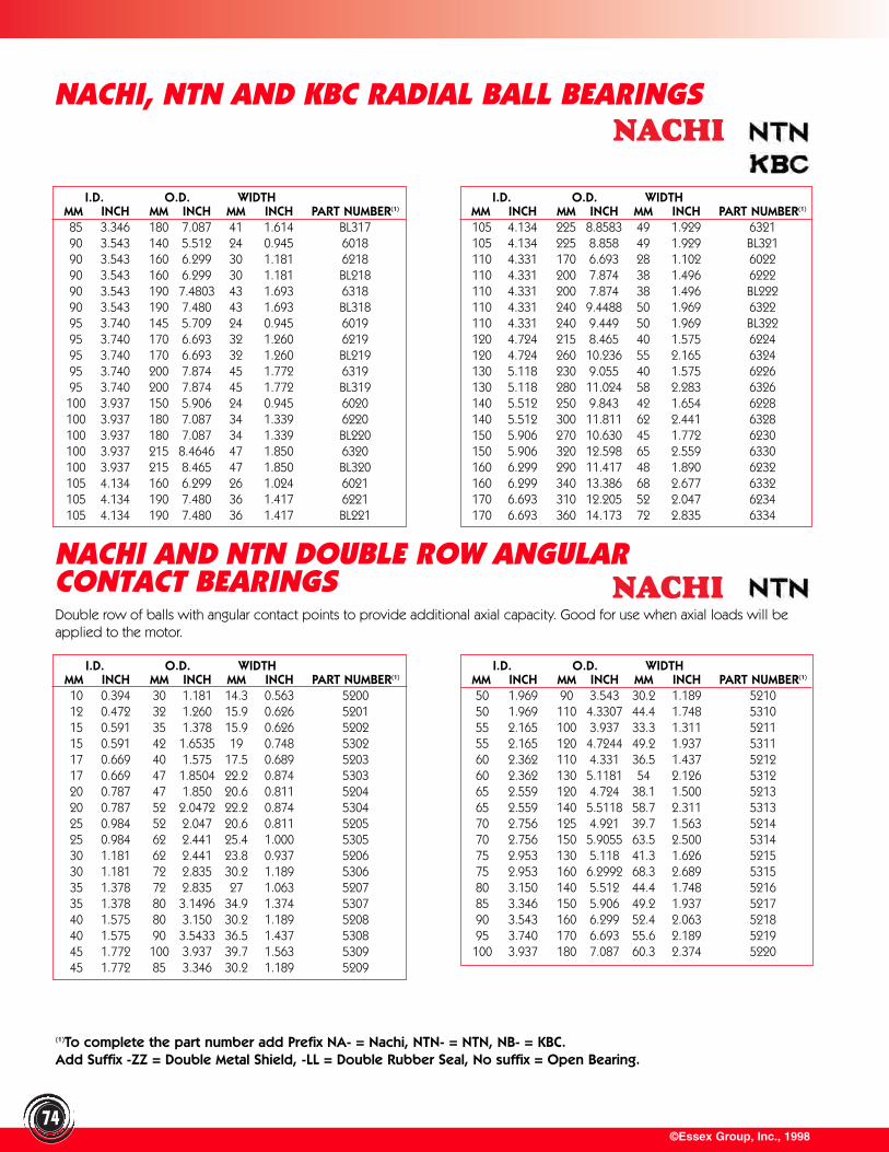
©Essex Group, Inc., 199874
I.D. O.D. WIDTHMM INCH MM INCH MM INCH PART NUMBER(1)
85 3.346 180 7.087 41 1.614 BL31790 3.543 140 5.512 24 0.945 601890 3.543 160 6.299 30 1.181 621890 3.543 160 6.299 30 1.181 BL21890 3.543 190 7.4803 43 1.693 631890 3.543 190 7.480 43 1.693 BL31895 3.740 145 5.709 24 0.945 601995 3.740 170 6.693 32 1.260 621995 3.740 170 6.693 32 1.260 BL21995 3.740 200 7.874 45 1.772 631995 3.740 200 7.874 45 1.772 BL319100 3.937 150 5.906 24 0.945 6020100 3.937 180 7.087 34 1.339 6220100 3.937 180 7.087 34 1.339 BL220100 3.937 215 8.4646 47 1.850 6320100 3.937 215 8.465 47 1.850 BL320105 4.134 160 6.299 26 1.024 6021105 4.134 190 7.480 36 1.417 6221105 4.134 190 7.480 36 1.417 BL221
I.D. O.D. WIDTHMM INCH MM INCH MM INCH PART NUMBER(1)
105 4.134 225 8.8583 49 1.929 6321105 4.134 225 8.858 49 1.929 BL321110 4.331 170 6.693 28 1.102 6022110 4.331 200 7.874 38 1.496 6222110 4.331 200 7.874 38 1.496 BL222110 4.331 240 9.4488 50 1.969 6322110 4.331 240 9.449 50 1.969 BL322120 4.724 215 8.465 40 1.575 6224120 4.724 260 10.236 55 2.165 6324130 5.118 230 9.055 40 1.575 6226130 5.118 280 11.024 58 2.283 6326140 5.512 250 9.843 42 1.654 6228140 5.512 300 11.811 62 2.441 6328150 5.906 270 10.630 45 1.772 6230150 5.906 320 12.598 65 2.559 6330160 6.299 290 11.417 48 1.890 6232160 6.299 340 13.386 68 2.677 6332170 6.693 310 12.205 52 2.047 6234170 6.693 360 14.173 72 2.835 6334
NACHI AND NTN DOUBLE ROW ANGULAR CONTACT BEARINGS
I.D. O.D. WIDTHMM INCH MM INCH MM INCH PART NUMBER(1)
10 0.394 30 1.181 14.3 0.563 520012 0.472 32 1.260 15.9 0.626 520115 0.591 35 1.378 15.9 0.626 520215 0.591 42 1.6535 19 0.748 530217 0.669 40 1.575 17.5 0.689 520317 0.669 47 1.8504 22.2 0.874 530320 0.787 47 1.850 20.6 0.811 520420 0.787 52 2.0472 22.2 0.874 530425 0.984 52 2.047 20.6 0.811 520525 0.984 62 2.441 25.4 1.000 530530 1.181 62 2.441 23.8 0.937 520630 1.181 72 2.835 30.2 1.189 530635 1.378 72 2.835 27 1.063 520735 1.378 80 3.1496 34.9 1.374 530740 1.575 80 3.150 30.2 1.189 520840 1.575 90 3.5433 36.5 1.437 530845 1.772 100 3.937 39.7 1.563 530945 1.772 85 3.346 30.2 1.189 5209
I.D. O.D. WIDTHMM INCH MM INCH MM INCH PART NUMBER(1)
50 1.969 90 3.543 30.2 1.189 521050 1.969 110 4.3307 44.4 1.748 531055 2.165 100 3.937 33.3 1.311 521155 2.165 120 4.7244 49.2 1.937 531160 2.362 110 4.331 36.5 1.437 521260 2.362 130 5.1181 54 2.126 531265 2.559 120 4.724 38.1 1.500 521365 2.559 140 5.5118 58.7 2.311 531370 2.756 125 4.921 39.7 1.563 521470 2.756 150 5.9055 63.5 2.500 531475 2.953 130 5.118 41.3 1.626 521575 2.953 160 6.2992 68.3 2.689 531580 3.150 140 5.512 44.4 1.748 521685 3.346 150 5.906 49.2 1.937 521790 3.543 160 6.299 52.4 2.063 521895 3.740 170 6.693 55.6 2.189 5219100 3.937 180 7.087 60.3 2.374 5220
(1)To complete the part number add Prefix NA- = Nachi, NTN- = NTN, NB- = KBC.Add Suffix -ZZ = Double Metal Shield, -LL = Double Rubber Seal, No suffix = Open Bearing.
Double row of balls with angular contact points to provide additional axial capacity. Good for use when axial loads will beapplied to the motor.
NACHI, NTN AND KBC RADIAL BALL BEARINGS
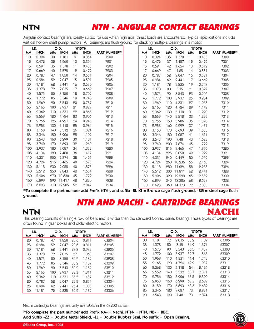
(1)To complete the part number add Prefix NTN-, and suffix -BL1G = Bronze cage flush ground, -BG = steel cage flushground.
©Essex Group, Inc., 1998
NTN - ANGULAR CONTACT BEARINGS
75
I.D. O.D. WIDTHMM INCH MM INCH MM INCH PART NUMBER(1)
10 0.394 30 1.181 9 0.354 720012 0.472 32 1.260 10 0.394 720115 0.591 35 1.378 11 0.433 720217 0.669 40 1.575 12 0.472 720320 0.787 47 1.850 14 0.551 720425 0.984 52 2.047 15 0.591 720530 1.181 62 2.441 16 0.630 720635 1.378 72 2.835 17 0.669 720740 1.575 80 3.150 18 0.709 720845 1.772 85 3.346 19 0.748 720950 1.969 90 3.543 20 0.787 721055 2.165 100 3.937 21 0.827 721160 2.362 110 4.331 22 0.866 721265 2.559 120 4.724 23 0.906 721370 2.756 125 4.921 24 0.945 721475 2.953 130 5.118 25 0.984 721580 3.150 140 5.512 26 1.024 721685 3.346 150 5.906 28 1.102 721790 3.543 160 6.299 30 1.181 721895 3.740 170 6.693 32 1.260 7219100 3.937 180 7.087 34 1.339 7220105 4.134 190 7.480 36 1.417 7221110 4.331 200 7.874 38 1.496 7222120 4.724 215 8.465 40 1.575 7224130 5.118 230 9.055 40 1.575 7226140 5.512 250 9.843 42 1.654 7228150 5.906 270 10.630 45 1.772 7230160 6.299 290 11.417 48 1.890 7232170 6.693 310 12.205 52 2.047 7234
I.D. O.D. WIDTHMM INCH MM INCH MM INCH PART NUMBER(1)
10 0.394 35 1.378 11 0.433 730012 0.472 37 1.457 12 0.472 730115 0.591 42 1.654 13 0.512 730217 0.669 47 1.85 14 0.551 730320 0.787 52 2.047 15 0.591 730425 0.984 62 2.441 17 0.669 730530 1.181 72 2.835 19 0.748 730635 1.378 80 3.15 21 0.827 730740 1.575 90 3.543 23 0.906 730845 1.772 100 3.937 25 0.984 730950 1.969 110 4.331 27 1.063 731055 2.165 120 4.724 29 1.142 731160 2.362 130 5.118 31 1.220 731265 2.559 140 5.512 33 1.299 731370 2.756 150 5.906 35 1.378 731475 2.953 160 6.299 37 1.457 731580 3.150 170 6.693 39 1.535 731685 3.346 180 7.087 41 1.614 731790 3.543 190 7.48 43 1.693 731895 3.740 200 7.874 45 1.772 7319100 3.937 215 8.465 47 1.850 7320105 4.134 225 8.858 49 1.929 7321110 4.331 240 9.449 50 1.969 7322120 4.724 260 10.236 55 2.165 7324130 5.118 280 11.024 58 2.283 7326140 5.512 300 11.811 62 2.441 7328150 5.906 320 12.598 65 2.559 7330160 6.299 340 13.386 68 2.677 7332170 6.693 360 14.173 72 2.835 7334
I.D. O.D. WIDTHMM INCH MM INCH MM INCH PART NUMBER(1)
20 0.787 47 1.850 20.6 0.811 6320425 0.984 52 2.047 20.6 0.811 6320530 1.181 62 2.441 23.8 0.937 6320635 1.378 72 2.835 27 1.063 6320740 1.575 80 3.150 30.2 1.189 6320845 1.772 85 3.346 30.2 1.189 6320950 1.969 90 3.543 30.2 1.189 6321055 2.165 100 3.937 33.3 1.311 6321160 2.362 110 4.331 36.5 1.437 6321220 0.787 52 2.047 22.2 0.874 6330425 0.984 62 2.441 25.4 1.000 6330530 1.181 72 2.835 30.2 1.189 63306
I.D. O.D. WIDTHMM INCH MM INCH MM INCH PART NUMBER(1)
30 1.181 72 2.835 30.2 1.189 6330635 1.378 80 3.15 34.9 1.374 6330740 1.575 90 3.543 36.5 1.437 6330845 1.772 100 3.937 39.7 1.563 6330950 1.969 110 4.331 44.4 1.748 6331055 2.165 120 4.724 49.2 1.937 6331160 2.362 130 5.118 54 2.126 6331265 2.559 140 5.512 58.7 2.311 6331370 2.756 150 5.906 63.5 2.500 6331475 2.953 160 6.299 68.3 2.689 6331580 3.150 170 6.693 68.3 2.689 6331685 3.346 180 7.087 73 2.874 6331790 3.543 190 7.48 73 2.874 63318
Nachi cartridge bearings are only available in the 63200 series.
NTN AND NACHI - CARTRIDGE BEARINGS
(1)To complete the part number add Prefix NA- = Nachi, NTN- = NTN, NB- = KBC.Add Suffix -ZZ = Double Metal Shield, -LL = Double Rubber Seal, No suffix = Open Bearing.
Angular contact bearings are ideally suited for use when high axial thrust loads are encountered. Typical applications includevertical hollow shaft pump motors. All bearings are flush ground for stacking multiple bearings in a motor.
This bearing consists of a single row of balls and is wider than the standard Conrad series bearing. These types of bearings areoften found in gear boxes and older electric motors.
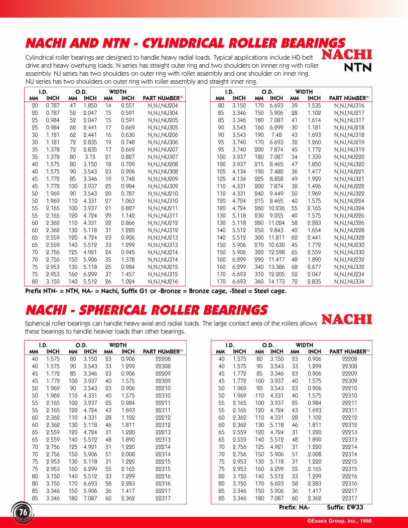
I.D. O.D. WIDTHMM INCH MM INCH MM INCH PART NUMBER(1)
40 1.575 80 3.150 23 0.906 2220840 1.575 90 3.543 33 1.299 2230845 1.772 85 3.346 23 0.906 2220945 1.772 100 3.937 40 1.575 2230950 1.969 90 3.543 23 0.906 2221050 1.969 110 4.331 40 1.575 2231055 2.165 100 3.937 25 0.984 2221155 2.165 120 4.724 43 1.693 2231160 2.362 110 4.331 28 1.102 2221260 2.362 130 5.118 46 1.811 2231265 2.559 120 4.724 31 1.220 2221365 2.559 140 5.512 48 1.890 2231370 2.756 125 4.921 31 1.220 2221470 2.756 150 5.906 51 2.008 2231475 2.953 130 5.118 31 1.220 2221575 2.953 160 6.299 55 2.165 2231580 3.150 140 5.512 33 1.299 2221680 3.150 170 6.693 58 2.283 2231685 3.346 150 5.906 36 1.417 2221785 3.346 180 7.087 60 2.362 22317
Prefix: NA- Suffix: EW33
©Essex Group, Inc., 1998
NACHI AND NTN - CYLINDRICAL ROLLER BEARINGS
76
I.D. O.D. WIDTHMM INCH MM INCH MM INCH PART NUMBER(1)
20 0.787 47 1.850 14 0.551 N,NJ,NU20420 0.787 52 2.047 15 0.591 N,NJ,NU30425 0.984 52 2.047 15 0.591 N,NJ,NU20525 0.984 62 2.441 17 0.669 N,NJ,NU30530 1.181 62 2.441 16 0.630 N,NJ,NU20630 1.181 72 2.835 19 0.748 N,NJ,NU30635 1.378 72 2.835 17 0.669 N,NJ,NU20735 1.378 80 3.15 21 0.827 N,NJ,NU30740 1.575 80 3.150 18 0.709 N,NJ,NU20840 1.575 90 3.543 23 0.906 N,NJ,NU30845 1.772 85 3.346 19 0.748 N,NJ,NU20945 1.772 100 3.937 25 0.984 N,NJ,NU30950 1.969 90 3.543 20 0.787 N,NJ,NU21050 1.969 110 4.331 27 1.063 N,NJ,NU31055 2.165 100 3.937 21 0.827 N,NJ,NU21155 2.165 120 4.724 29 1.142 N,NJ,NU31160 2.362 110 4.331 22 0.866 N,NJ,NU21260 2.362 130 5.118 31 1.220 N,NJ,NU31265 2.559 120 4.724 23 0.906 N,NJ,NU21365 2.559 140 5.512 33 1.299 N,NJ,NU31370 2.756 125 4.921 24 0.945 N,NJ,NU21470 2.756 150 5.906 35 1.378 N,NJ,NU31475 2.953 130 5.118 25 0.984 N,NJ,NU21575 2.953 160 6.299 37 1.457 N,NJ,NU31580 3.150 140 5.512 26 1.024 N,NJ,NU216
I.D. O.D. WIDTHMM INCH MM INCH MM INCH PART NUMBER(1)
80 3.150 170 6.693 39 1.535 N,NJ,NU31685 3.346 150 5.906 28 1.102 N,NJ,NU21785 3.346 180 7.087 41 1.614 N,NJ,NU31790 3.543 160 6.299 30 1.181 N,NJ,NU21890 3.543 190 7.48 43 1.693 N,NJ,NU31895 3.740 170 6.693 32 1.260 N,NJ,NU21995 3.740 200 7.874 45 1.772 N,NJ,NU319100 3.937 180 7.087 34 1.339 N,NJ,NU220100 3.937 215 8.465 47 1.850 N,NJ,NU320105 4.134 190 7.480 36 1.417 N,NJ,NU221105 4.134 225 8.858 49 1.929 N,NJ,NU321110 4.331 200 7.874 38 1.496 N,NJ,NU222110 4.331 240 9.449 50 1.969 N,NJ,NU322120 4.724 215 8.465 40 1.575 N,NJ,NU224120 4.724 260 10.236 55 2.165 N,NJ,NU324130 5.118 230 9.055 40 1.575 N,NJ,NU226130 5.118 280 11.024 58 2.283 N,NJ,NU326140 5.512 250 9.843 42 1.654 N,NJ,NU228140 5.512 300 11.811 62 2.441 N,NJ,NU328150 5.906 270 10.630 45 1.772 N,NJ,NU230150 5.906 320 12.598 65 2.559 N,NJ,NU330160 6.299 290 11.417 48 1.890 N,NJ,NU232160 6.299 340 13.386 68 2.677 N,NJ,NU332170 6.693 310 12.205 52 2.047 N,NJ,NU234170 6.693 360 14.173 72 2.835 N,NJ,NU334
NACHI - SPHERICAL ROLLER BEARINGSSpherical roller bearings can handle heavy axial and radial loads. The large contact area of the rollers allows these bearings to handle heavier loads than other bearings.
Prefix NTN- = NTN, NA- = Nachi, Suffix G1 or -Bronze = Bronze cage, -Steel = Steel cage.
Cylindrical roller bearings are designed to handle heavy radial loads. Typical applications include HD beltdrive and heavy overhung loads. N series has straight outer ring and two shoulders on innner ring with rollerassembly. NJ series has two shoulders on outer ring with roller assembly and one shoulder on inner ring.NU series has two shoulders on outer ring with roller assembly and straight inner ring.
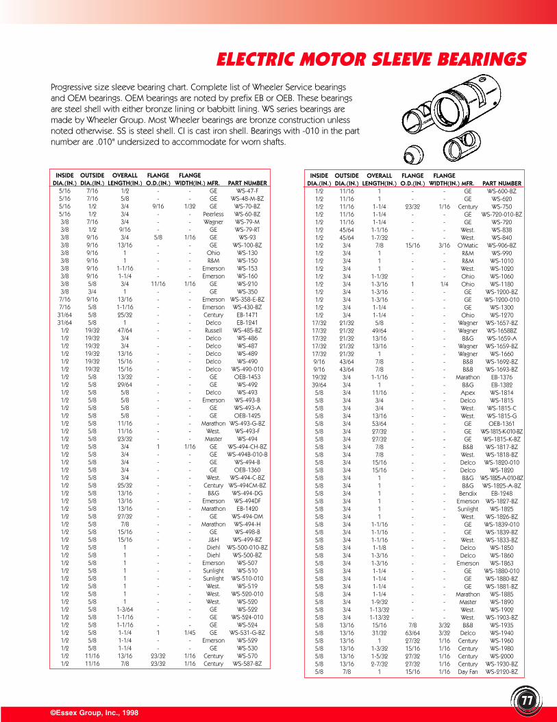
©Essex Group, Inc., 199877
ELECTRIC MOTOR SLEEVE BEARINGSProgressive size sleeve bearing chart. Complete list of Wheeler Service bearingsand OEM bearings. OEM bearings are noted by prefix EB or OEB. These bearingsare steel shell with either bronze lining or babbitt lining. WS series bearings aremade by Wheeler Group. Most Wheeler bearings are bronze construction unlessnoted otherwise. SS is steel shell. CI is cast iron shell. Bearings with -010 in the partnumber are .010" undersized to accommodate for worn shafts.
INSIDE OUTSIDE OVERALL FLANGE FLANGEDIA.(IN.) DIA.(IN.) LENGTH(IN.) O.D.(IN.) WIDTH(IN.) MFR. PART NUMBER
5/16 7/16 1/2 - - GE WS-47-F5/16 7/16 5/8 - - GE WS-48-M-BZ5/16 1/2 3/4 9/16 1/32 GE WS-70-BZ5/16 1/2 3/4 - - Peerless WS-60-BZ3/8 7/16 3/4 - - Wagner WS-79-M3/8 1/2 9/16 - - GE WS-79-RT3/8 9/16 3/4 5/8 1/16 GE WS-933/8 9/16 13/16 - - GE WS-100-BZ3/8 9/16 1 - - Ohio WS-1303/8 9/16 1 - - R&M WS-1503/8 9/16 1-1/16 - - Emerson WS-1533/8 9/16 1-1/4 - - Emerson WS-1603/8 5/8 3/4 11/16 1/16 GE WS-2103/8 3/4 1 - - GE WS-3507/16 9/16 13/16 - - Emerson WS-358-E-BZ7/16 5/8 1-1/16 - - Emerson WS-430-BZ31/64 5/8 25/32 - - Century EB-147131/64 5/8 1 - - Delco EB-12411/2 19/32 47/64 - - Russell WS-485-BZ1/2 19/32 3/4 - - Delco WS-4861/2 19/32 3/4 - - Delco WS-4871/2 19/32 13/16 - - Delco WS-4891/2 19/32 15/16 - - Delco WS-4901/2 19/32 15/16 - - Delco WS-490-0101/2 5/8 13/32 - - GE OEB-14531/2 5/8 29/64 - - GE WS-4921/2 5/8 5/8 - - Delco WS-4931/2 5/8 5/8 - - Emerson WS-493-B1/2 5/8 5/8 - - GE WS-493-A1/2 5/8 5/8 - - GE OEB-14251/2 5/8 11/16 - - Marathon WS-493-G-BZ1/2 5/8 11/16 - - West. WS-493-F1/2 5/8 23/32 - - Master WS-4941/2 5/8 3/4 1 1/16 GE WS-494-CH-BZ1/2 5/8 3/4 - - GE WS-494B-010-B1/2 5/8 3/4 - - GE WS-494-B1/2 5/8 3/4 - - GE OEB-13601/2 5/8 3/4 - - West. WS-494-C-BZ1/2 5/8 25/32 - - Century WS-494CM-BZ1/2 5/8 13/16 - - B&G WS-494-DG1/2 5/8 13/16 - - Emerson WS-494DF1/2 5/8 13/16 - - Marathon EB-14201/2 5/8 27/32 - - GE WS-494-DM1/2 5/8 7/8 - - Marathon WS-494-H1/2 5/8 15/16 - - GE WS-498-B1/2 5/8 15/16 - - J&H WS-499-BZ1/2 5/8 1 - - Diehl WS-500-010-BZ1/2 5/8 1 - - Diehl WS-500-BZ1/2 5/8 1 - - Emerson WS-5071/2 5/8 1 - - Sunlight WS-5101/2 5/8 1 - - Sunlight WS-510-0101/2 5/8 1 - - West. WS-5191/2 5/8 1 - - West. WS-520-0101/2 5/8 1 - - West. WS-5201/2 5/8 1-3/64 - - GE WS-5221/2 5/8 1-1/16 - - GE WS-524-0101/2 5/8 1-1/16 - - GE WS-5241/2 5/8 1-1/4 1 1/45 GE WS-531-G-BZ1/2 5/8 1-1/4 - - Emerson WS-5291/2 5/8 1-1/4 - - GE WS-5301/2 11/16 13/16 23/32 1/16 Century WS-5701/2 11/16 7/8 23/32 1/16 Century WS-587-BZ
INSIDE OUTSIDE OVERALL FLANGE FLANGEDIA.(IN.) DIA.(IN.) LENGTH(IN.) O.D.(IN.) WIDTH(IN.) MFR. PART NUMBER
1/2 11/16 1 - - GE WS-600-BZ1/2 11/16 1 - - GE WS-6201/2 11/16 1-1/4 23/32 1/16 Century WS-7501/2 11/16 1-1/4 - - GE WS-720-010-BZ1/2 11/16 1-1/4 - - GE WS-7201/2 45/64 1-1/16 - - West. WS-8381/2 45/64 1-7/32 - - West. WS-8401/2 3/4 7/8 15/16 3/16 O'Matic WS-906-BZ1/2 3/4 1 - - R&M WS-9901/2 3/4 1 - - R&M WS-10101/2 3/4 1 - - West. WS-10201/2 3/4 1-1/32 - - Ohio WS-10601/2 3/4 1-3/16 1 1/4 Ohio WS-11801/2 3/4 1-3/16 - - GE WS-1200-BZ1/2 3/4 1-3/16 - - GE WS-1200-0101/2 3/4 1-1/4 - - GE WS-13001/2 3/4 1-1/4 - - Ohio WS-1270
17/32 21/32 5/8 - - Wagner WS-1657-BZ17/32 21/32 49/64 - - Wagner WS-1658BZ17/32 21/32 13/16 - - B&G WS-1659-A17/32 21/32 13/16 - - Wagner WS-1659-BZ17/32 21/32 1 - - Wagner WS-16609/16 43/64 7/8 - - B&B WS-1692-BZ9/16 43/64 7/8 - - B&B WS-1693-BZ19/32 3/4 1-1/16 - - Marathon EB-137639/64 3/4 1 - - B&G EB-13825/8 3/4 11/16 - - Apex WS-18145/8 3/4 3/4 - - Delco WS-18155/8 3/4 3/4 - - West. WS-1815-C5/8 3/4 13/16 - - West. WS-1815-G5/8 3/4 53/64 - - GE OEB-13615/8 3/4 27/32 - - GE WS-1815-K-010-BZ5/8 3/4 27/32 - - GE WS-1815-K-BZ5/8 3/4 7/8 - - B&B WS-1817-BZ5/8 3/4 7/8 - - West. WS-1818-BZ5/8 3/4 15/16 - - Delco WS-1820-0105/8 3/4 15/16 - - Delco WS-18205/8 3/4 1 - - B&G WS-1825-A-010-BZ5/8 3/4 1 - - B&G WS-1825-A-BZ5/8 3/4 1 - - Bendix EB-12485/8 3/4 1 - - Emerson WS-1827-BZ5/8 3/4 1 - - Sunlight WS-18255/8 3/4 1 - - West. WS-1826-BZ5/8 3/4 1-1/16 - - GE WS-1839-0105/8 3/4 1-1/16 - - GE WS-1839-BZ5/8 3/4 1-1/16 - - West. WS-1833-BZ5/8 3/4 1-1/8 - - Delco WS-18505/8 3/4 1-3/16 - - Delco WS-18605/8 3/4 1-3/16 - - Emerson WS-18635/8 3/4 1-1/4 - - GE WS-1880-0105/8 3/4 1-1/4 - - GE WS-1880-BZ5/8 3/4 1-1/4 - - GE WS-1881-BZ5/8 3/4 1-1/4 - - Marathon WS-18855/8 3/4 1-9/32 - - Master WS-18905/8 3/4 1-13/32 - - West. WS-19025/8 3/4 1-13/32 - - West. WS-1903-BZ5/8 13/16 15/16 7/8 3/32 B&B WS-19355/8 13/16 31/32 63/64 3/32 Delco WS-19405/8 13/16 1 27/32 1/16 Century WS-19605/8 13/16 1-3/32 15/16 1/16 Century WS-19805/8 13/16 1-5/32 27/32 1/16 Century WS-20005/8 13/16 2-7/32 27/32 1/16 Century WS-1930-BZ5/8 7/8 1 15/16 1/16 Day Fan WS-2120-BZ
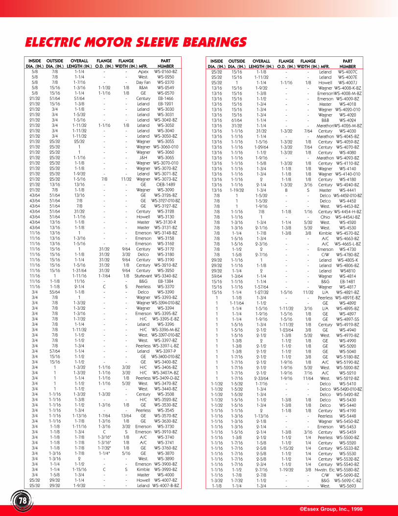
INSIDE OUTSIDE OVERALL FLANGE FLANGE PARTDIA. (IN.) DIA. (IN.) LENGTH (IN.) O.D. (IN.) WIDTH (IN.) MFR. NUMBER
5/8 7/8 1-1/4 - - Apex WS-2160-BZ5/8 7/8 1-1/4 - - West. WS-22505/8 7/8 1-7/16 - - Day Fan WS-23705/8 15/16 1-3/16 1-1/32 1/8 R&M WS-25495/8 15/16 1-1/4 1-1/16 1/8 GE WS-2570
21/32 51/64 51/64 - - Century EB-146621/32 15/16 1-3/8 - - Leland EB-120121/32 3/4 1-1/8 - - Leland WS-303021/32 3/4 1-5/32 - - Leland WS-303121/32 3/4 1-5/16 - - Leland WS-3042-BZ21/32 3/4 1-11/32 1-1/16 1/8 Leland WS-305221/32 3/4 1-11/32 - - Leland WS-304021/32 3/4 1-11/32 - - Leland WS-3050-BZ21/32 25/32 25/32 - - Wagner WS-305521/32 25/32 1 - - Wagner WS-3060-01021/32 25/32 1 - - Wagner WS-306021/32 25/32 1-1/16 - - J&H WS-306521/32 25/32 1-1/8 - - Wagner WS-3070-01021/32 25/32 1-1/8 - - Wagner WS-3070-BZ21/32 25/32 1-9/32 - - Leland WS-3071-BZ21/32 25/32 1-5/16 7/8 11/32 Wagner WS-3073-BZ21/32 13/16 13/16 - - GE OEB-148921/32 7/8 1-1/8 - - Wagner WS-309043/64 51/64 13/16 - - GE WS-3126-BZ43/64 51/64 7/8 - - GE WS-3127-010-BZ43/64 51/64 7/8 - - GE WS-3127-BZ43/64 51/64 31/32 - - Century WS-312843/64 51/64 1-1/16 - - Howell WS-313043/64 13/16 1-1/8 - - Master WS-3130-R43/64 13/16 1-1/8 - - Master WS-3131-BZ11/16 13/16 1 - - Emerson WS-3148-BZ11/16 13/16 1-3/16 - - Emerson WS-315811/16 13/16 1-5/16 - - Emerson WS-316211/16 15/16 1 31/32 9/64 Century WS-317211/16 15/16 1-1/8 31/32 3/32 Delco WS-318011/16 15/16 1-1/4 31/32 9/64 Century WS-319011/16 15/16 1-5/16 31/32 1/8 Century WS-3210-BZ11/16 15/16 1-31/64 31/32 9/64 Century WS-325011/16 1 1-11/16 1-7/64 1/8 Sturtevant WS-3340-BZ11/16 1-1/8 11/16 - - B&G EB-138411/16 1-1/8 2-1/4 C S Peerless WS-3370
3/4 55/64 1-1/8 - - Delco WS-33903/4 7/8 1 - - Wagner WS-3393-BZ3/4 7/8 1-3/32 - - Wagner WS-3394-010-BZ3/4 7/8 1-3/32 - - Wagner WS-33943/4 7/8 1-3/16 - - Emerson WS-3395-BZ3/4 7/8 1-7/32 - - H/C WS-3395-E-BZ3/4 7/8 1-1/4 - - Leland WS-33963/4 7/8 1-11/32 - - H/C WS-3396-M-BZ3/4 7/8 1-1/2 - - West. WS-3397-010-BZ3/4 7/8 1-1/2 - - West. WS-3397-BZ3/4 7/8 1-3/4 - - Peerless WS-3397-L-BZ3/4 57/64 1-1/4 - - Leland WS-3397-P3/4 15/16 1-1/2 - - GE WS-3400-010-BZ3/4 15/16 1-1/2 - - GE WS-3400-BZ3/4 1 1-3/32 1-1/16 3/32 H/C WS-3406-BZ3/4 1 1-3/32 1-1/16 3/32 H/C WS-3407A-BZ3/4 1 1-1/4 1-1/16 1/8 Peerless WS-3409-D-BZ3/4 1 1-1/2 1-1/16 5/32 West. WS-3470-BZ3/4 1 1-1/2 - - West. WS-3440-BZ3/4 1-1/16 1-3/32 1-3/32 - Century WS-35083/4 1-1/16 1-3/8 - - H/C WS-3520-BZ3/4 1-1/16 1-1/2 1-3/16 1/8 GE WS-3530-BZ3/4 1-1/16 1-3/4 - - Peerless WS-35453/4 1-1/16 1-13/16 1-7/64 13/64 GE WS-3570-BZ3/4 1-1/16 1-7/8 1-3/16 1/8 GE WS-3630-BZ3/4 1-1/8 1-11/16 1-3/16 3/32 Emerson WS-37303/4 1-1/8 1-3/4 C S Emerson WS-3910-BZ3/4 1-1/8 1-7/8 1-3/16" 1/8 A/C WS-37403/4 1-1/8 1-7/8 1-3/16" 1/8 A/C WS-37413/4 1-1/8 1-7/8 1-7/32" 1/8 GE WS-3760-BZ3/4 1-3/16 1-7/8 1-1/4" 5/16 GE WS-38703/4 1-3/16 2 - - West. WS-38903/4 1-1/4 1-1/2 - - Emerson WS-3900-BZ3/4 1-1/4 1-15/16 C S Kimble WS-3920-BZ3/4 1-5/8 1-3/4 - - Master WS-4000
25/32 29/32 1-1/4 - - Howell WS-4007-BZ25/32 29/32 1-9/32 - - Leland WS-4007-B-BZ
©Essex Group, Inc., 199878
ELECTRIC MOTOR SLEEVE BEARINGSINSIDE OUTSIDE OVERALL FLANGE FLANGE PART
DIA. (IN.) DIA. (IN.) LENGTH (IN.) O.D. (IN.) WIDTH (IN.) MFR. NUMBER25/32 15/16 1-1/8 - - Leland WS-4007C25/32 15/16 1-11/32 - - Leland WS-4007E25/32 1 1-1/4 1-1/16 1/8 Howell WS-4007J13/16 15/16 1-9/32 - - Wagner WS-4008-K-BZ13/16 15/16 1-3/8 - - EmersonWS-4008-M-BZ13/16 15/16 1-1/2 - - Emerson WS-4009-BZ13/16 15/16 1-3/4 - - Master WS-401813/16 15/16 1-3/4 - - Wagner WS-4020-01013/16 15/16 1-3/4 - - Wagner WS-402013/16 61/64 1-1/4 - - B&B WS-402413/16 31/32 1-1/4 - - MarathonWS-4026-M-BZ13/16 1-1/16 31/32 1-3/32 7/64 Century WS-403013/16 1-1/16 1-1/4 - - Marathon WS-4045-BZ13/16 1-1/16 1-5/16 1-3/32 1/8 Century WS-4059-BZ13/16 1-1/16 1-29/64 1-3/32 7/64 Century WS-4070-BZ13/16 1-1/16 1-1/2 1-3/32 1/8 Century WS-408013/16 1-1/16 1-9/16 - - Marathon WS-4093-BZ13/16 1-1/16 1-5/8 1-3/32 1/8 Century WS-4110-BZ13/16 1-1/16 1-3/4 1-1/8 1/8 Wagner WS-414013/16 1-1/16 1-3/4 1-1/8 1/8 Wagner WS-4140-01013/16 1-1/16 2 1-1/8 1/8 Century WS-418013/16 1-1/16 2-1/4 1-3/32 3/16 Century WS-4240-BZ13/16 1-19/32 1-3/4 B S Master WS-44417/8 1 1-5/32 - - Delco WS-4452-010-BZ7/8 1 1-5/32 - - Delco WS-44527/8 1 1-9/16 - - West. WS-4453-BZ7/8 1-1/16 7/8 1-1/8 1/16 Century WS-4454-H-BZ7/8 1-1/16 1 - - Ohio WS-4454J-BZ7/8 1-3/16 1-3/4 1-1/4 5/32 West. WS-45207/8 1-3/16 2-1/16 1-3/8 5/32 West. WS-45307/8 1-1/4 1-7/8 1-3/8 3/8 Kimble WS-4570-BZ7/8 1-5/16 1-3/4 - - A/C WS-4663-BZ7/8 1-5/16 2-3/16 - - A/C WS-4665-L-BZ7/8 1-1/2 2 - - Emerson WS-47307/8 1-5/8 2-7/16 - - C/W WS-4780-BZ
29/32 1-1/16 1 - - Leland WS-4805-K29/32 1-1/16 1-1/8 - - Leland WS-4806-BZ29/32 1-1/4 2 - - Leland WS481059/64 1-3/64 1-1/4 - - Wagner WS-481415/16 1-1/16 1-1/4 - - B&G EB-148115/16 1-1/16 1-57/64 - - Wagner WS-481715/16 1-1/4 1-27/32 1-5/16 11/32 L/A WS-4821-BZ
1 1-1/8 1-3/4 - - Peerless WS-4891E-BZ1 1-11/64 1-1/2 - - GE WS-48921 1-1/4 1-5/16 1-11/32 3/16 L/A WS-4895-BZ1 1-1/4 1-9/16 1-5/16 1/8 GE WS-48971 1-1/4 1-9/16 1-5/16 1/8 GE WS-4897-SS1 1-5/16 1-3/4 1-11/32 1/8 Century WS-4919-BZ1 1-5/16 2-1/2 1-23/64 3/8 GE WS-49401 1-5/16 2-1/2 1-3/8 5/32 West. WS-4970-BZ1 1-3/8 2 1-1/2 1/8 GE WS-49901 1-3/8 2-1/2 1-1/2 1/8 GE WS-50201 1-3/8 2-1/2 1-1/2 1/8 GE WS-50401 1-7/16 2-1/2 1-1/2 3/8 GE WS-5180-BZ1 1-7/16 2-1/2 1-9/16 1/8 A/C WS-5190-BZ1 1-7/16 2-1/2 1-9/16 5/32 West. WS-5200-BZ1 1-7/16 2-1/2 1-9/16 7/16 A/C WS-52101 1-7/16 2-33/64 1-9/16 11/64 West. WS-5212-BZ
1-1/32 1-5/32 1-7/16 - - Delco WS-54101-1/32 1-5/32 1-3/4 - - Delco WS-5420-010-BZ1-1/32 1-5/32 1-3/4 - - Delco WS-5420-BZ1-1/32 1-5/16 1-1/2 1-3/8 1/8 Delco WS-54301-1/32 1-5/16 1-3/4 1-3/8 1/8 Delco WS-54401-1/16 1-1/16 2 1-1/8 1/8 Century WS-41901-1/16 1-3/16 1-13/16 - - Peerless WS-54481-1/16 1-3/16 2-1/8 - - Wagner WS-5450-BZ1-1/16 1-3/16 2-1/4 - - Emerson WS-54531-1/16 1-5/16 2-1/4 1-3/8 3/16 Century WS-54591-1/16 1-3/8 2-1/2 1-1/2 1/4 Peerless WS-5500-BZ1-1/16 1-7/16 1-5/8 1-1/2 1/4 Century WS-55201-1/16 1-7/16 2-5/8 1-15/32 1/4 Century WS-5533-BZ1-1/16 1-7/16 2-5/8 1-1/2 1/4 Century WS-55301-1/16 1-7/16 2-5/8 1-1/2 1/4 Century WS-5532-BZ1-1/16 1-7/16 2-3/4 1-1/2 1/4 Century WS-5540-BZ1-1/16 1-1/2 2-7/16 1-19/32 3/8 Nwstn. Elc.WS-5580-BZ1-1/16 1-7/8 2-7/8 - - C/W WS-5690-BZ1-3/32 1-7/32 1-1/2 - - B&G WS-5692-C-BZ1-1/8 1-1/4 1-3/4 - - West. WS-5693
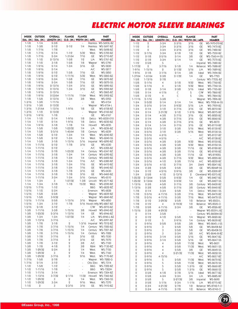
©Essex Group, Inc., 199879
ELECTRIC MOTOR SLEEVE BEARINGSINSIDE OUTSIDE OVERALL FLANGE FLANGE PART
DIA. (IN.) DIA. (IN.) LENGTH (IN.) O.D. (IN.) WIDTH (IN.) MFR. NUMBER1-1/8 1-1/4 2-3/8 - - Peerless WS-5693L-BZ1-1/8 1-3/8 2-1/2 2-1/2 1/4 Peerless WS-5697-BZ1-1/8 1-7/16 1-7/8 - - West. WS-5698-BZ1-1/8 1-7/16 2-1/4 1-1/2 5/32 West. WS-5700-BZ1-1/8 1-7/16 2-3/4 1-31/64 7/16 GE WS-5710-BZ1-1/8 1-1/2 2-13/16 1-5/8 1/2 L/A WS-5761-BZ1-1/8 1-1/2 3-1/8 1-5/8 1/8 Wagner WS-57901-1/8 1-9/16 2-1/4 1-3/4 3/16 GE WS-58301-1/8 1-9/16 2-1/4 - - A/C WS-58171-1/8 1-9/16 2-1/2 1-5/8 7/16 GE WS-58501-1/8 1-9/16 2-1/2 1-11/16 5/32 West. WS-5860-BZ1-1/8 1-9/16 2-3/4 1-5/8 7/16 GE WS-5870-BZ1-1/8 1-9/16 2-3/4 1-5/8 7/16 GE WS-5870-SS1-1/8 1-9/16 2-13/16 1-3/4 3/16 GE WS-5890-BZ1-1/8 1-9/16 2-13/16 1-3/4 3/16 GE WS-5900-BZ1-1/8 1-9/16 2-13/16 - - A/C WS-5865-BZ1-1/8 1-9/16 2-53/64 1-11/16 11/64 West. WS-5902-BZ1-1/8 1-5/8 2-13/16 1-3/4 3/8 West. WS-59501-3/16 1-3/8 1-11/16 - - GE WS-61541-3/16 1-3/8 2-13/32 - - Wagner WS-6154-L1-3/16 1-31/64 1-13/16 1-9/16 1/8 GE WS-6158-BZ1-3/16 1-1/2 2-13/32 - - Wagner WS-6160-BZ1-3/16 1-9/16 1-7/8 - - GE WS-61671-1/4 1-1/2 2-1/4 1-9/16 1/8 Delco WS-6230-0101-1/4 1-1/2 2-1/4 1-9/16 1/8 Delco WS-6230-BZ1-1/4 1-9/16 3-1/8 1-7/8 1/4 Howell WS-62351-1/4 1-5/8 1-5/8 1-23/32 1/4 L/A WS-6236-BZ1-1/4 1-5/8 2-5/16 1-45/64 1/8 Century WS-62391-1/4 1-5/8 2-1/2 1-3/4 1/4 West. WS-6240-BZ1-1/4 1-5/8 2-1/2 1-3/4 1/4 West. WS-6240-SS1-1/4 1-5/8 3-1/8 1-13/16 5/16 Imperial WS-6290-BZ1-1/4 1-11/16 2-1/2 1-7/8 3/16 GE WS-63301-1/4 1-11/16 2-1/2 - - A/C WS-6326-BZ1-1/4 1-11/16 2-7/8 1-23/32 1/4 Century WS-6347-BZ1-1/4 1-11/16 3-1/8 1-3/4 1/4 Century WS-6390-BZ1-1/4 1-11/16 3-1/8 1-3/4 1/4 Century WS-6400-BZ1-1/4 1-11/16 3-1/8 1-3/4 7/16 A/C WS-6380-BZ1-1/4 1-11/16 3-1/8 1-3/4 7/16 GE WS-6410-BZ1-1/4 1-11/16 3-1/8 1-3/4 7/16 GE WS-6440-BZ1-1/4 1-11/16 3-1/8 1-7/8 3/16 GE WS-64301-1/4 1-11/16 3-1/8 1-7/8 3/16 GE WS-6460-BZ1-1/4 1-11/16 3-3/4 1-3/4 5/16 Century WS-65101-1/4 1-3/4 3 1-27/32 1-3/8 Lincoln WS-6571-BZ1-1/4 1-3/4 3-1/8 1-7/8 15/32 West. WS-6590-BZ1-5/16 1-7/16 1-1/2 - - B&G WS-6832-BZ1-5/16 1-1/2 2-3/4 - - Emerson WS-68381-5/16 1-5/8 2-5/8 - - Wagner WS-6839-BZ1-5/16 1-5/8 3-9/32 - - Wagner WS-6840-BZ1-5/16 1-11/16 2-5/8 1-13/16 3/16 Wagner WS-68501-5/16 1-3/4 3-1/2 1-7/8 5/16 Nwstn Mfg.WS-6867-BZ1-5/16 2-1/8 3-1/2 - - C/W WS-6910-BZ1-3/8 1-11/16 3-3/8 1-15/16 3/8 Howell WS-6943-BZ1-3/8 1-23/32 2-3/16 1-13/16 1/4 GE WS-6946-BZ1-3/8 1-3/4 1-3/4 1-27/32 1/4 L/A WS-6946-L-BZ1-3/8 1-13/16 3-7/16 - - A/C WS-6991-BZ1-3/8 1-7/8 3-1/8 2 1-3/16 Imperial WS-7012-BZ1-3/8 1-7/8 3-7/16 1-15/16 1/4 Century WS-7020-BZ1-3/8 1-7/8 3-7/16 1-15/16 1/4 Century WS-7021-BZ1-3/8 1-7/8 3-7/16 1-15/16 1/4 Century WS-70221-3/8 1-7/8 3-7/16 2 3/16 GE WS-70301-3/8 1-7/8 3-7/16 2 3/16 GE WS-70701-3/8 1-7/8 3-1/2 2 3/8 A/C WS-71001-3/8 1-7/8 4-1/8 2 3/8 R&M WS-7130-BZ1-3/8 1-29/32 2-3/4 2 1/4 West. WS-71501-3/8 1-29/32 3 2 1/4 West. WS-71601-3/8 1-29/32 3-7/16 2 9/16 West. WS-7170-BZ1-7/16 1-5/8 2-7/8 - - Wagner WS-7282-G1-7/16 2-1/4 3-1/2 - - Otis Elev. WS-73141-1/2 1-5/8 1-1/2 - - B&G WS-7322-BZ1-1/2 1-11/16 1-7/8 - - B&G WS-7323H1-1/2 1-11/16 3-1/4 - - Emerson WS-7324-BZ1-1/2 1-13/16 3-7/32 2-1/16 11/32 Howell WS-7360-BZ1-1/2 1-29/32 3 2 1/4 West. WS-7360-SS1-1/2 1-29/32 3-3/4 2 9/16 West. WS-73701-1/2 2 3 2-3/16 3/16 GE WS-7410-BZ
INSIDE OUTSIDE OVERALL FLANGE FLANGE PARTDIA. (IN.) DIA. (IN.) LENGTH (IN.) O.D. (IN.) WIDTH (IN.) MFR. NUMBER
1-1/2 2 3-3/4 2-3/16 3/16 GE WS-7470-010-BZ1-1/2 2 3-3/4 2-3/16 3/16 GE WS-7470-BZ1-1/2 2 3-3/4 2-3/16 3/16 GE WS-7480-BZ1-1/2 2-1/16 3-3/4 2-1/8 1/2 GE WS-7550-BZ1-1/2 2-1/8 2-5/16 2-1/4 3/8 GE WS-7560-H-SS1-1/2 2-1/8 3-3/4 2-1/4 1/4 GE WS-7570-BZ1-1/2 2-5/8 5 - - Imperial WS-7680-BZ
1-17/32 2 3-7/16 2-1/8 1/4 Reliance WS-7688-BZ1-9/16 1-15/16 2 2-1/32 5/16 L/A WS-7689-BZ1-9/16 2-1/8 3-1/16 2-1/4 3/8 Ideal WS-7694-BZ1-37/64 1-61/64 2-3/8 2-1/32 1/4 GE WS-77231-5/8 1-13/16 2-7/8 - - Century WS-7723L-BZ1-5/8 2-1/16 4 2-1/8 9/32 West. WS-7760-BZ1-5/8 2-1/16 4 2-1/8 9/32 West. WS-7760-SS1-5/8 2-1/8 3-1/4 2-3/8 5/16 Ideal WS-7765-BZ1-5/8 2-1/4 4-1/16 C S C/W WS-7860-BZ1-5/8 2-1/2 4 C S Otis WS-7864-BZ
1-11/16 2-1/16 3-3/8 - - Wagner WS-7896-BZ1-3/4 2-5/32 2-1/4 2-1/4 1/4 West. WS-7958-M-SS1-3/4 2-3/16 2-1/4 2-9/32 5/16 L/A WS-7959-BZ1-3/4 2-1/4 3-1/2 2-7/16 3/16 GE WS-8010-BZ1-3/4 2-1/4 3-31/32 2-1/2 1-3/16 West. WS-8015-BZ1-3/4 2-1/4 4-3/8 2-7/16 3/16 GE WS-8020-BZ1-3/4 2-1/4 4-3/8 2-7/16 3/16 GE WS-8060-BZ1-3/4 2-1/4 4-3/8 2-7/16 3/16 GE WS-80701-3/4 2-1/4 5-1/4 2-7/16 3/16 GE WS-8110-BZ1-3/4 2-5/16 3-1/2 2-3/8 5/16 West. WS-8130-BZ1-3/4 2-5/16 3-1/2 2-3/8 5/16 West. WS-8130-SS1-3/4 2-5/16 4-3/16 - - A/C WS-8137-BZ1-3/4 2-5/16 4-5/16 - - A/C WS-8138-BZ1-3/4 2-5/16 4-3/8 2-3/8 9/32 West. WS-8150-BZ1-3/4 2-5/16 4-3/8 2-3/8 9/32 West. WS-8150-SS1-3/4 2-5/16 4-3/8 2-3/8 11/16 GE WS-8180-BZ1-3/4 2-5/16 4-3/8 2-3/8 11/16 GE WS-8190-BZ1-3/4 2-5/16 4-3/8 2-3/8 11/16 GE WS-8190SS1-3/4 2-5/16 4-3/8 2-7/16 9/32 West. WS-8220-BZ1-3/4 2-5/16 4-1/2 2-3/8 11/16 A/C WS-8230-BZ1-3/4 2-5/16 4-1/2 2-7/16 3/4 Diehl WS-8241-BZ1-3/4 2-3/8 2-5/8 2-5/8 3/8 GE WS-8244P-SS1-3/4 2-1/2 4-5/16 2-9/16 3/8 GE WS-8300-BZ1-3/4 2-5/8 4-1/2 2-13/16 2 Cleveland WS-8315-BZ
1-25/32 2-13/64 2-5/8 2-9/32 1/4 GE WS-8427-BZ1-25/32 2-13/64 2-5/8 2-9/32 1/4 GE WS-8427-SS1-13/16 2-3/8 4-5/8 2-7/16 3/8 Century WS-8430-BZ1-13/16 2-3/8 4-5/8 2-7/16 3/8 Century WS-8440-BZ1-7/8 2-1/4 3-3/4 2-5/8 1/4 Delco WS-8461-SS1-7/8 2-5/16 4-11/16 2-3/8 7/16 West. WS-8470-BZ1-7/8 2-5/16 4-11/16 2-3/8 7/16 West. WS-8470-SS1-7/8 2-1/2 3-29/32 2-5/8 1/2 Reliance WS-8503-L1-7/8 2-1/2 4 2-19/32 1/2 Reliance WS-8505-CI1-7/8 2-5/8 4-11/16 2-3/4 3/8 GE WS-8526-BZ
1-15/16 2-3/8 4-29/32 - - Wagner WS-8559-L-BZ2 2-1/4 3-5/8 - - Century WS-8602M-BZ2 2-1/2 4-1/2 2-5/8 1/4 Wagner WS-8620-BZ2 2-1/2 5 2-9/16 1/4 Century WS-8630-BZ2 2-9/16 2-5/8 2-5/8 3/8 West. WS-8645-J-SS2 2-9/16 3 2-5/8 5/8 GE WS-8645R-BZ2 2-9/16 3 2-5/8 5/8 GE WS-8645R-SS2 2-9/16 3 2-3/4 3/8 A/C WS-8646-B-BZ2 2-9/16 3-1/4 2-5/8 5/16 GE WS-8647-BZ2 2-9/16 3-1/4 2-5/8 5/16 GE WS-8647-SS2 2-9/16 4 2-5/8 11/32 West. WS-86512 2-9/16 4 2-5/8 11/32 West. WS-8651-SS2 2-9/16 4 2-5/8 3/8 GE WS-8649-SS2 2-9/16 4 2-21/32 11/32 West. WS-8652-SS2 2-9/16 4-15/16 - - A/C WS-8657-BZ2 2-9/16 5 2-5/8 11/32 West. WS-8670-BZ2 2-9/16 5 2-5/8 11/32 West. WS-8670-SS2 2-9/16 5 2-5/8 1-3/16 GE WS-8660-BZ2 2-9/16 5 2-5/8 1-3/16 GE WS-8660-SS2 2-5/8 4-1/8 2-7/8 5/16 Ideal WS-8677-BZ2 2-5/8 4-3/4 2-3/4 3/4 L/A WS-8685-BZ2 2-5/8 5 2-27/32 3/8 Imperial WS-86902 2-5/8 5-1/16 2-3/4 1-1/16 L/A WS-8715-BZ2 2-3/4 4-21/32 2-7/8 1/2 Reliance WS-8742-F-CI2 2-3/4 4-11/16 2-7/8 1/2 Reliance WS-8743-CI
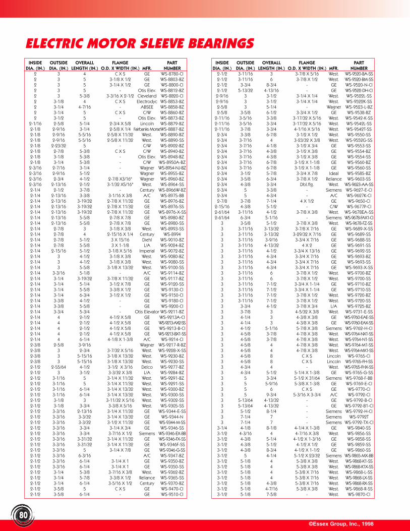
©Essex Group, Inc., 199880
ELECTRIC MOTOR SLEEVE BEARINGSINSIDE OUTSIDE OVERALL FLANGE PART
DIA. (IN.) DIA. (IN.) LENGTH (IN.) O.D. X WIDTH (IN.) MFR. NUMBER2 3 4 C X S GE WS-8780-CI2 3 5 3-1/8 X 1/2 GE WS-8803-BZ2 3 5 3-1/4 X 1/2 GE WS-8800-CI2 3 5 - Otis Elev. WS-8812-BZ2 3 5-3/8 3-3/16 X 2-1/2 Cleveland WS-8820-CI2 3-1/8 4 C X S Electrodyc WS-8853-BZ2 3-1/4 4-7/16 - ABSEE WS-8858-BZ2 3-1/4 5 C X S C/W WS-8860-BZ2 3-1/2 5 - Otis Elev. WS-8873-BZ
2-1/16 2-5/8 5-1/4 2-3/4 X 5/8 Lincoln WS-8879-BZ2-1/8 2-9/16 3-1/4 2-5/8 X 1/4 Fairbanks MorseWS-8887-BZ2-1/8 2-9/16 5-5/16 2-5/8 X 11/32 West. WS-8890-BZ2-1/8 2-9/16 5-5/16 2-5/8 X 11/32 West. WS-8890-SS2-1/8 2-23/32 5 - C/W WS-8902-BZ2-1/8 2-7/8 5-3/8 C X S C/W WS-8940-BZ2-1/8 3-1/8 5-3/8 - Otis Elev. WS-8948-BZ2-1/8 3-1/4 5-3/8 - C/W WS-8950A-BZ2-3/16 2-7/16 3-1/4 - Wagner WS-8954-NJ-BZ2-3/16 2-9/16 5-1/2 - Wagner WS-8955-BZ2-3/16 2-3/4 4-1/2 2-7/8 X3/16" Wagner WS-8960-BZ2-3/16 2-13/16 2-1/2 3-1/32 X5/16" West. WS-8964-SS2-1/4 2-1/2 3-7/8 - Century WS-8966W-BZ2-1/4 2-13/16 3-3/8 3-1/16 X 3/8 A/C WS-8975-BB2-1/4 2-13/16 3-19/32 2-7/8 X 11/32 GE WS-8976-BZ2-1/4 2-13/16 3-19/32 2-7/8 X 11/32 GE WS-8976-SS2-1/4 2-13/16 3-19/32 2-7/8 X 11/32 GE WS-8976-X-SS2-1/4 2-13/16 5-5/8 2-7/8 X 7/8 GE WS-8980-BZ2-1/4 2-13/16 5-5/8 2-7/8 X 7/8 GE WS-8980-SS2-1/4 2-7/8 3 3-1/8 X 3/8 West. WS-8993-SS2-1/4 2-7/8 4 2-15/16 X 1/4 Century WS-89942-1/4 2-7/8 5-1/2 3 X 15/16 Diehl WS-9010-BZ2-1/4 2-7/8 5-5/8 3 X 1-1/8 L/A WS-9024-BZ2-1/4 2-15/16 5-1/2 3-1/8 X 5/16 Imperial WS-9072-BZ2-1/4 3 4-1/2 3-1/8 X 3/8 West. WS-9080-BZ2-1/4 3 4-1/2 3-1/8 X 3/8 West. WS-9080-SS2-1/4 3 5-5/8 3-1/8 X 13/32 West. WS-9100-SS2-1/4 3-3/16 5-1/8 - A/C WS-9114-BZ2-1/4 3-1/4 3-19/32 3-7/8 X 11/32 GE WS-9117-BZ2-1/4 3-1/4 5-1/4 3-1/2 X 7/8 GE WS-9120-SS2-1/4 3-1/4 5-5/8 3-3/8 X 1/2 GE WS-9130-CI2-1/4 3-1/4 6-3/4 3-1/2 X 1/2 GE WS-9150-CI2-1/4 3-3/8 4-1/2 - GE WS-9180-CI2-1/4 3-3/8 5-5/8 - GE WS-9200-CI2-1/4 3-3/4 5-3/4 - Otis Elevator WS-9211-BZ2-1/4 4 2-1/2 4-1/2 X 5/8 GE WS-9213A-CI2-1/4 4 2-1/2 4-1/2 X 5/8 GE WS-9213-AX2-SS2-1/4 4 2-1/2 4-1/2 X 5/8 GE WS-9213-B-CI2-1/4 4 2-1/2 4-1/2 X 5/8 GE WS-9213-BX1-SS2-1/4 4 6-1/4 4-1/8 X 1-3/8 A/C WS-9214-CI2-3/8 2-5/8 3-9/16 - Wagner WS-9217-R-BZ2-3/8 3 2-3/4 3-7/32 X 5/16 West. WS-9228-X-SS2-3/8 3 5-15/16 3-1/8 X 13/32 West. WS-9230-BZ2-3/8 3 5-15/16 3-1/8 X 13/32 West. WS-9230-SS2-1/2 2-55/64 4-1/2 3-1/2 X 3/16 Delco WS-9277-BZ2-1/2 3 3-1/2 3-3/32 X 3/8 L/A WS-9284-BZ2-1/2 3-1/16 5 3-1/4 X 11/32 West. WS-9291-BZ2-1/2 3-1/16 5 3-1/4 X 11/32 West. WS-9291-SS2-1/2 3-1/16 6-1/4 3-1/4 X 13/32 West. WS-9300-BZ2-1/2 3-1/16 6-1/4 3-1/4 X 13/32 West. WS-9300-SS2-1/2 3-1/8 3 3-11/32 X 5/16 West. WS-9302-SS2-1/2 3-1/8 3-3/4 3-3/8 X 5/16 West. WS-9305-SS2-1/2 3-3/16 2-13/16 3-1/4 X 11/32 GE WS-9344-E-SS2-1/2 3-3/16 3-3/32 3-1/4 X 13/32 GE WS-9344-N2-1/2 3-3/16 3-3/32 3-1/2 X 11/32 GE WS-9344-M-SS2-1/2 3-3/16 3-3/4 3-1/4 X 3/4 GE WS-9346-SS2-1/2 3-3/16 3-3/4 3-7/16 X 1/2 Siemens WS-9346-EX-BB2-1/2 3-3/16 3-31/32 3-1/4 X 11/32 GE WS-9346-FX-SS2-1/2 3-3/16 3-31/32 3-1/4 X 11/32 GE WS-9346F-SS2-1/2 3-3/16 5 3-1/4 X 7/8 GE WS-9346-G-SS2-1/2 3-3/16 6-3/16 - A/C WS-9347-BZ2-1/2 3-3/16 6-1/4 3-1/4 X 1 GE WS-9350-BZ2-1/2 3-3/16 6-1/4 3-1/4 X 1 GE WS-9350-SS2-1/2 3-1/4 5-3/8 3-7/16 X 3/8 West. WS-9362-BZ2-1/2 3-1/4 5-7/8 3-3/8 X 1/2 Reliance WS-9365-SS2-1/2 3-1/4 6-1/4 3-5/16 X 1/2 Century WS-9370-BZ2-1/2 3-5/8 5 C X S GE WS-9470-CI2-1/2 3-5/8 6-1/4 - GE WS-9510-CI
INSIDE OUTSIDE OVERALL FLANGE PARTDIA. (IN.) DIA. (IN.) LENGTH (IN.) O.D. X WIDTH (IN.) MFR. NUMBER
2-1/2 3-11/16 3 3-7/8 X 5/16 West. WS-9520-BA-SS2-1/2 3-11/16 6 3-7/8 X 1/2 West. WS-9520-BM-SS2-1/2 3-3/4 8-3/4 - GE WS-9520-N-CI2-1/2 5-13/32 4-13/16 - GE WS-9522-DH-CI2-9/16 3 3-1/2 3-1/4 X 1/4 West. WS-9522L-SS2-9/16 3 3-1/2 3-1/4 X 1/4 West. WS-9522K-SS2-5/8 3 5-1/4 - Wagner WS-9523-L-BZ2-5/8 3-5/8 6-1/2 3-3/4 X 1/2 GE WS-9538-BZ
2-11/16 3-5/16 3-3/8 3-17/32 X 5/16 West. WS-9542-K-SS2-11/16 3-5/16 3-3/4 3-17/32 X 5/16 West. WS-9542L-SS2-11/16 3-7/8 3-3/4 4-1/16 X 5/16 West. WS-9542T-SS2-3/4 3-3/8 6-7/8 3-1/2 X 1/2 West. WS-9550-SS2-3/4 3-7/16 4 3-23/32 X 3/8 West. WS-9552G-SS2-3/4 3-7/16 4-1/8 3-1/2 X 3/4 GE WS-9553-SS2-3/4 3-7/16 4-3/8 3-1/2 X 3/8 GE WS-9554-BZ2-3/4 3-7/16 4-3/8 3-1/2 X 3/8 GE WS-9554-SS2-3/4 3-7/16 6-7/8 3-1/2 X 1-1/8 GE WS-9560-BZ2-3/4 3-7/16 6-7/8 3-1/2 X 1-1/8 GE WS-9560-SS2-3/4 3-1/2 5-7/8 3-3/4 X 7/8 Ideal WS-9585-BZ2-3/4 3-5/8 6-3/4 3-7/8 X 1/2 Reliance WS-9603-SS2-3/4 4-3/8 3-3/4 Dbl.flg. West. WS-9623-AA-SS2-3/4 5 3-3/8 - Siemens WS-9627-E-CI2-3/4 5 4-3/4 - A/C WS-9627K-CI2-7/8 3-7/8 7-1/4 4 X 1/2 GE WS-9650-CI
2-15/16 4-3/8 5-1/2 - C/W WS-9677P-CI2-61/64 3-11/16 4-1/2 3-7/8 X 3/8 West. WS-9678EA-SS2-61/64 6-3/4 5-1/16 - Siemens WS-9678-FAX1-CI
3 3-5/8 5-1/2 3-7/8 X 3/8 West. WS-9678-FZ-SS3 3-11/16 3-13/32 3-7/8 X 7/16 GE WS-9689-X-SS3 3-11/16 3-13/32 3-29/32 X 7/16 GE WS-9689-SS3 3-11/16 3-9/16 3-3/4 X 7/16 GE WS-9688-SS3 3-11/16 4-13/32 4 X 2 GE WS-9691-SS3 3-11/16 4-1/2 3-3/4 X 13/16 GE WS-9692-SS3 3-11/16 4-3/4 3-3/4 X 7/16 GE WS-9693-BZ3 3-11/16 4-3/4 3-3/4 X 7/16 GE WS-9693-SS3 3-11/16 4-3/4 3-3/4 X 7/16 GE WS-9693-X-SS3 3-11/16 6 3-7/8 X 1/2 West. WS-9700-BZ3 3-11/16 6 3-7/8 X 1/2 West. WS-9700-SS3 3-11/16 7-1/2 3-3/4 X 1-1/4 GE WS-9710-BZ3 3-11/16 7-1/2 3-3/4 X 1-1/4 GE WS-9710-SS3 3-11/16 7-1/2 3-7/8 X 1/2 West. WS-9720-BZ3 3-11/16 7-1/2 3-7/8 X 1/2 West. WS-9720-SS3 3-3/4 4-1/2 3-7/8 X 3/4 L/A WS-9725-BZ3 3-7/8 3 4-5/32 X 3/8 West. WS-9731-E-SS3 4-1/4 3 4-3/8 X 3/8 GE WS-9760-EAE-SS3 4-1/4 3 4-3/8 X 3/8 GE WS-9760-EAX-SS3 4-1/2 5-1/16 5-7/8 X 3/8 Siemens WS-9762-H-CI3 4-5/8 3-7/8 4-7/8 X 3/8 West. WS-9764-NX1-SS3 4-5/8 3-7/8 4-7/8 X 3/8 West. WS-9764-N1-SS3 4-5/8 4 4-7/8 X 3/8 West. WS-9764-M1-SS3 4-5/8 4 4-7/8 X 3/8 West. WS-9764-MX1-SS3 4-5/8 8 C X S Lincoln WS-9765-CI3 4-5/8 8 C X S Lincoln WS-9765-FH-SS3 4-3/4 4 - West. WS-9765-FHX-SS3 4-3/4 5-1/2 5-1/4 X 1-3/8 GE WS-9765-G-SS3 5 3-3/4 5-1/2 X 31/64 Siemens WS-9768-F-BB3 5 5-9/16 5-3/8 X 1-3/8 GE WS-9769-E-CI3 5 6 C X S GE WS-9770-CI3 5 9-3/4 5-3/16 X 3-3/4 A/C WS-9792-CI3 5-13/64 4-13/32 - GE WS-9792-B-CI3 5-13/64 4-13/32 - GE WS-9792-B1-CI3 5-1/2 8-1/4 - Siemens WS-9792-H-CI3 7-1/4 7 - Siemens WS-9792T3 7-1/4 7 - Siemens WS-9792-TX-CI
3-1/4 4-1/8 8-1/8 4-1/4 X 1-3/8 GE WS-9840-SS3-1/2 4-3/16 4 4-7/16 X 3/8 West. WS-9856-SS3-1/2 4-3/8 5-1/4 4-1/2 X 1-3/16 GE WS-9858-SS3-1/2 4-3/8 5-1/2 4-1/2 X 1/2 GE WS-9859-SS3-1/2 4-3/8 8-3/4 4-1/2 X 1-1/2 GE WS-9860-SS3-1/2 5 4-1/4 5-1/2 X 23/32 Siemens WS-9865-MX-BB3-1/2 5-1/8 4 5-3/8 X 3/8 West. WS-9868-K1-SS3-1/2 5-1/8 4 5-3/8 X 3/8 West. WS-9868-K1X-SS3-1/2 5-1/8 4 5-3/8 X 7/16 West. WS-9868-L-SS3-1/2 5-1/8 4 5-3/8 X 7/16 West. WS-9868-LX-SS3-1/2 5-1/8 4-3/8 5-3/8 X 7/16 West. WS-9868-RX-SS3-1/2 5-1/8 4-7/16 5-3/8 X 3/8 West. WS-9868-R-SS3-1/2 5-1/8 7-5/8 - West. WS-9870-CI
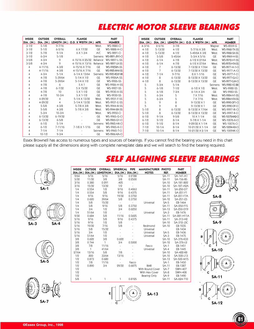
©Essex Group, Inc., 1998
ELECTRIC MOTOR SLEEVE BEARINGS
81
INSIDE OUTSIDE OVERALL FLANGE PARTDIA. (IN.) DIA. (IN.) LENGTH (IN.) O.D. X WIDTH (IN.) MFR. NUMBER
3-1/2 5-1/8 9-7/16 - West. WS-9880-CI3-1/2 5-1/2 6-5/16 6 X 17/32 GE WS-9888-H-CI3-1/2 5-7/8 9-1/4 6 X 1-3/4 A/C WS-9891-CI3-1/2 6-3/4 5-1/8 - Siemens WS-9891-JFX1-CI3-5/8 4-3/4 9 4-15/16 X 25/32 Reliance WS-9897-L-SS3-5/8 4-3/4 9 4-15/16 X 13/16 Reliance WS-9897-LX-SS
4 4-11/16 4-3/8 4-15/16 X 7/16 GE WS-9925RA-SS4 4-11/16 4-3/8 4-15/16 X 7/16 GE WS-9925-RAX-SS4 4-3/4 5-1/4 6-1/4 X 13/64 Siemens WS-9925-REX/F-BB4 4-7/8 5-39/64 5-1/4 X 1/2 GE WS-9926A-SS4 4-7/8 5-39/64 5-1/4 X 1/2 GE WS-9926-SS4 4-7/8 6 5 X 1 GE WS-9926-H-SS4 4-7/8 6-7/32 5 X 15/32 GE WS-9927-SS4 4-7/8 10 5 X 1-1/2 GE WS-9930-X-SS4 4-7/8 10-3/4 5 X 1-1/2 GE WS-9930-SS4 4-29/32 4 5-1/4 X 13/32 West. WS-9931-F-SS4 4-29/32 4 5-1/4 X 13/32 West. WS-9931-E-SS4 5-5/8 4-3/8 5-7/8 X 3/8 West. WS-9944-B-SS4 5-5/8 4-3/8 5-7/8 X 3/8 West. WS-9944-BX-SS4 5-3/4 10-3/4 - West. WS-9950-CI4 6-13/32 6-19/32 - GE WS-9965-G-CI4 6-13/32 6-5/8 - GE WS-9965-G1-CI4 6-1/2 5-1/4 - Seimens WS-9965-HX-CI4 6-1/2 7-11/16 7-1/8 X 1-1/16 GE WS-9965-K-CI4 7-1/4 7-1/4 - Seimens WS-9965-T-CI4 10-1/2 9-3/4 - GE WS-9966-KA-CI
INSIDE OUTSIDE OVERALL FLANGE PARTDIA. (IN.) DIA. (IN.) LENGTH (IN.) O.D. X WIDTH (IN.) MFR. NUMBER
4-3/16 2-5/16 3-7/8 - Wagner WS-8559-G4-1/2 5-13/32 4-1/2 5-7/16 X 3/8 West. WS-9968-TX-SS4-1/2 5-13/32 4-1/2 5-49/64 X 3/8 West. WS-9968-SX-SS4-1/2 5-5/8 5-45/64 5-3/4 X 5/16 GE WS-9969-H-SS4-1/2 6-1/4 4-7/8 6-1/2 X 27/64 West. WS-9972-H1-SS4-1/2 6-1/4 4-7/8 6-1/2 X 27/64 West. WS-9972-H1X-SS4-1/2 7 6-13/32 7-13/32 X 17/64 GE WS-9977-A-1-CI4-1/2 7 6-13/32 7-13/32 X 13/32 GE WS-9977-A-CI4-1/2 7-1/4 9-7/16 8 X 1-1/16 GE WS-9977-F-CI4-1/2 8 6-13/32 8-13/32 X 13/32 GE WS-9977-GJ-CI4-1/2 8 6-13/32 8-13/32 X 13/32 GE WS-9977-GJX-CI
5 5-3/4 5-1/4 - Seimens WS-9980-YZ-BB5 6-1/8 7-1/2 6-1/2 X 1/2 West. WS-9982-SS5 6-1/8 7-3/4 6-1/4 X 3/4 GE WS-9983-SS5 6-3/4 5 7 X 7/16 West. WS-9984-N1-SS5 6-3/4 5 7 X 7/16 West. WS-9984-N1X-SS5 9 8 9-13/32 X 1 GE WS-9990-DF1-CI5 9 8 9-13/32 X 1 GE WS-9990-DF-CI
5-1/2 8 6-13/32 8-13/32 X 17/64 GE WS-9997-RI-CI5-1/2 8 6-13/32 8-13/32 X 13/32 GE WS-9997-R-CI6-1/2 9-1/4 9-5/8 10 X 1-1/4 GE WS-10075MX2-CI6-1/2 9-1/2 8-1/4 9-7/8 X 1-1/4 GE WS-10076-X-CI6-1/2 9-1/2 8-1/4 9-29/32 X 1-1/4 GE WS-10076-CI7-1/2 10-1/4 8-1/4 10-21/32 X 1-1/4 GE WS-10094-KX-CI7-1/2 10-1/4 8-1/4 10-21/32 X 2-1/4 GE WS-10094K-CI
Essex Brownell has access to numerous types and sources of bearings. If you cannot find the bearing you need in this chartplease supply all the dimensions along with complete nameplate data and we will search to find the bearing required.
INSIDE OUTSIDE OVERALL SPHERICAL PIPE MANUFACTURER PHOTO PARTDIA.(IN.) DIA.(IN.) LENGTH(IN.) DIA.(IN.) DIA.(IN.) NOTES REF. NUMBER9/64 5/16 5/16 5/16 0.2188 SA-11 SA-141-A15/32 11/32 3/8 3/8 0.2500 SA-11 SA-156-B53/16 0.380 0.291 .405 - SA-10 SA-181-B223/16 15/32 13/32 1/2 - SA-10 SA-187-A2A1/4 0.554 1/2 9/16 0.4063 SA-11 SA-250-D71/4 0.554 5/8 9/16 0.4375 SA-11 SA-251-F11/4 9/16 9/16 19/32 0.3750 SA-11 SA-251-F7A1/4 0.620 39/64 5/8 0.3750 SA-12 SA-251-E51/4 5/8 15/32 - - Universal SA-5 EB-14641/4 5/8 9/16 5/8 0.3750 SA-11 SA-250-F151/4 3/4 1/2 3/4 0.6250 SA-13 SA-250-D191/4 51/64 1/2 - - Universal SA-3 EB-14769/32 0.684 5/8 11/16 0.5625 SA-11 SA-281-H11A5/16 9/16 5/8 9/16 0.4375 SA-11 SA-313-H25/16 9/16 1/2 5/8 - SA-10 SA-312-J3C5/16 19/32 7/16 5/8 - Redmond SA-10 EB-12355/16 5/8 15/32 - - Universal - EB-14345/16 3/4 1/2 - - Universal SA-5 EB-14365/16 51/64 1/2 - - Universal SA-3 EB-14753/8 0.622 3/8 0.622 - SA-10 SA-376-K333/8 0.744 1 3/4 0.5000 SA-12 SA-376-L23/8 7/8 11/16 - - Fasco SA-1 EB-14513/8 1 41/64 - - Universal SA-4 EB-1445
27/64 13/16 5/8 7/8 - SA-10 SA-422-K81/2 .800 33/64 13/16 - SA-10 SA-502-L131/2 0.873 0.680 - - SA-13 SA-500-M151/2 7/8 11/16 - Fasco SA-1 EB-14501/2 0.890 3/4 29/32 0.6875 RMR SA-11 EB-13871/2 With Round Cover SA-7 SWH-4071/2 With Hex Cover SA-8 SWH-4081/2 Bearing Only SA-9 EB-14905/8 1 1 1 0.8125 SA-11 SA-624-T10
SA-1
SELF ALIGNING SLEEVE BEARINGS
SA-3 SA-4
SA-5
SA-7
SA-8
SA-9
SA-10
SA-11
SA-12
SA-13
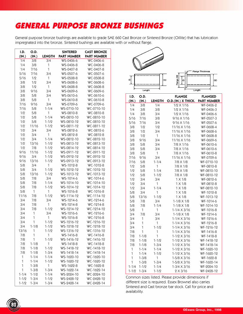
©Essex Group, Inc., 199882
GENERAL PURPOSE BRONZE BUSHINGSGeneral purpose bronze bushings are available to grade SAE 660 Cast Bronze or Sintered Bronze (Oillite) that has lubricationimpregnated into the bronze. Sintered bushings are available with or without flange.
I.D. O.D. SINTERED CAST BRONZE(IN.) (IN.) LENGTH PART NUMBER PART NUMBER1/4 3/8 3/4 WS-0406-6 WC-0406-61/4 3/8 1 WS-0406-8 WC-0406-81/4 7/16 1 WS-0407-8 WC-0407-85/16 7/16 3/4 WS-0507-6 WC-0507-65/16 1/2 1 WS-0508-8 WC-0508-83/8 1/2 3/4 WS-0608-6 WC-0608-63/8 1/2 1 WS-0608-8 WC-0608-83/8 9/16 3/4 WS-0609-6 WC-0609-63/8 5/8 3/4 WS-0610-6 WC-0610-63/8 5/8 1 WS-0610-8 WC-0610-87/16 9/16 3/4 WS-0709-6 WC-0709-67/16 5/8 1-1/4 WS-0710-10 WC-0710-101/2 5/8 1 WS-0810-8 WC-0810-81/2 5/8 1-1/4 WS-0810-10 WC-0810-101/2 5/8 1-1/2 WS-0810-12 WC-0810-121/2 11/16 1-1/2 WS-0811-12 WC-0811-121/2 3/4 3/4 WS-0812-6 WC-0812-61/2 3/4 1 WS-0812-8 WC-0812-81/2 3/4 1-1/4 WS-0812-10 WC-0812-101/2 13/16 1-1/2 WS-0813-12 WC-0813-121/2 7/8 1-1/2 WS-0814-12 WC-0814-129/16 11/16 1-1/2 WS-0911-12 WC-0911-129/16 3/4 1-1/2 WS-0912-12 WC-0912-129/16 13/16 1-1/2 WS-0913-12 WC-0913-125/8 3/4 1 WS-1012-8 WC-1012-85/8 3/4 1-1/2 WS-1012-12 WC-1012-125/8 13/16 1-1/2 WS-1013-12 WC-1013-125/8 7/8 3/4 WS-1014-6 WC-1014-65/8 7/8 1-1/4 WS-1014-10 WC-1014-105/8 7/8 1-1/2 WS-1014-12 WC-1014-125/8 1 1 WS-1016-8 WC-1016-8
11/16 7/8 1-1/2 WS-1114-12 WC-1114-123/4 7/8 3/4 WS-1214-6 WC-1214-63/4 7/8 1 WS-1214-8 WC-1214-83/4 7/8 1-1/2 WS-1214-12 WC-1214-123/4 1 3/4 WS-1216-6 WC-1216-63/4 1 1 WS-1216-8 WC-1216-83/4 1 1-1/2 WS-1216-12 WC-1216-123/4 1-1/8 1-1/2 WS-1218-12 WC-1218-12
13/16 1 1-1/2 WS-1316-12 WC-1316-127/8 1 1 WS-1416-8 WC-1416-87/8 1 1-1/2 WS-1416-12 WC-1416-127/8 1-1/8 1 WS-1418-8 WC-1418-87/8 1-1/8 1-1/2 WS-1418-12 WC-1418-127/8 1-1/8 1-3/4 WS-1418-14 WC-1418-141 1-1/4 1-1/4 WS-1620-10 WC-1620-101 1-1/4 1-1/2 WS-1620-12 WC-1620-121 1-3/8 1 WS-1622-8 WC-1622-81 1-3/8 1-3/4 WS-1622-14 WC-1622-14
1-1/4 1-1/2 1-1/4 WS-2024-10 WC-2024-101-1/2 1-3/4 1-1/2 WS-2428-12 WC-2428-121-1/2 1-3/4 1-3/4 WS-2428-14 WC-2428-14
I.D. O.D. FLANGE FLANGED(IN.) (IN.) LENGTH O.D.(IN.) X THICK. PART NUMBER1/4 3/8 1/4 1/2 X 1/16 WF-0406-21/4 3/8 3/8 1/2 X 1/16 WF-0406-31/4 3/8 3/4 1/2 X 1/16 WF-0406-65/16 7/16 3/8 9/16 X 1/16 WF-0507-35/16 7/16 3/4 9/16 X 1/16 WF-0507-63/8 1/2 1/2 11/16 X 1/16 WF-0608-43/8 1/2 3/4 11/16 X 1/16 WF-0608-63/8 1/2 1 11/16 X 1/16 WF-0608-83/8 9/16 3/4 11/16 X 1/16 WF-0609-63/8 5/8 3/4 7/8 X 1/16 WF-0610-63/8 5/8 3/4 7/8 X 1/16 WF-0610-63/8 5/8 1 7/8 X 1/16 WF-0610-87/16 9/16 3/4 11/16 X 1/16 WF-0709-67/16 5/8 1-1/4 7/8 X 1/8 WF-0710-101/2 5/8 1 7/8 X 1/8 WF-0810-81/2 5/8 1-1/4 7/8 X 1/8 WF-0810-101/2 5/8 1-1/2 7/8 X 1/8 WF-0810-121/2 3/4 3/4 1 X 1/8 WF-0812-61/2 3/4 1 1 X 1/8 WF-0812-81/2 3/4 1-1/4 1 X 1/8 WF-0812-105/8 3/4 1 1 X 1/8 WF-1012-85/8 13/16 1-1/2 1 X 1/8 WF-1013-125/8 7/8 3/4 1-1/8 X 1/8 WF-1014-65/8 7/8 1-1/4 1-1/8 X 1/8 WF-1014-105/8 1 1 1-1/4 X 3/16 WF-1016-83/4 7/8 3/4 1-1/8 X 1/8 WF-1214-63/4 1 3/4 1-1/4 X 3/16 WF-1216-63/4 1 1 1-1/4 X 3/16 WF-1216-83/4 1 1-1/2 1-1/4 X 3/16 WF-1216-127/8 1 1 1-1/4 X 3/16 WF-1416-87/8 1-1/8 1 1-1/2 X 3/16 WF-1418-87/8 1-1/8 1-1/2 1-1/2 X 3/16 WF-1418-127/8 1-1/8 1-3/4 1-1/2 X 3/16 WF-1418-141 1-1/4 1-1/4 1-1/2 X 3/16 WF-1620-101 1-1/4 1-1/2 1-1/2 X 3/16 WF-1620-121 1-3/8 1 1-5/8 X 3/16 WF-1622-81 1-3/8 1-3/4 1-5/8 X 3/16 WF-1622-14
1-1/4 1-1/2 1-1/4 1-3/4 X 3/16 WF-2024-101-1/2 1-3/4 1-1/2 2 X 3/16 WF-2428-12
Common sizes listed. Please provide dimensions ifdifferent size is required. Essex Brownel also carriesSintered and Cast bronze bar stock. Call for price andavailability.
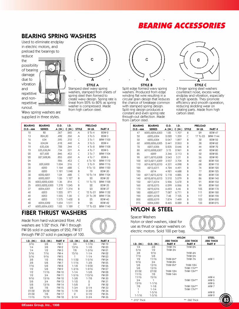
NYLON STEEL.020 THICK .030 THICK .020 THICK
I.D. (IN.) O.D. (IN.) PART # PART # PART #1/4 3/8 TNW-1N TNW-2N5/16 1/2 TNW-3N3/8 9/16 TNW-4N
7/16 5/8 TNW-5N1/2 11/16 TNW-6N* TNW-7N MW-19/16 3/4 TNW-8N5/8 13/16 TNW-9N* TNW-10N5/8 13/16 TNW-11N**
21/32 27/32 TNW-12N TNW-13N**11/16 7/8 TNW-14N11/16 15/16 MW-43/4 1 TNW-15N** MW-5
13/16 1-1/16 MW-67/8 1-1/8 TNW-16N** MW-71 1-1/4 TNW-17N**1 1-5/16 MW-8
1-1/16 1-5/16 MW-9
©Essex Group, Inc., 199883
BEARING ACCESSORIES
STYLE AStamped steel wavy springwashers, stamped from sheets ofspring steel then formed tocreate wavy design. Spring rate islineal from 20% to 80% as springwasher is compressed. Madefrom high carbon steel.
STYLE B Split edge formed wavy springwashers. Produced from edgewinding flat wire resulting in acircular grain design that reducesthe chance of breakage commonwith stamped spring design.Split ring design produces aconstant and even spring ratethrough-out deflection. Madefrom carbon steel.
STYLE C 3 finger spring steel washerscounteract noise, excess wear,endplay and vibration, especiallyat high speeds. They promoteefficiency and smooth operation,reducing skidding wear onrotating parts. Made from highcarbon steel.
BEARING BEARING O.D. I.D. PRELOADO.D.--MM SERIES A (IN.) C (IN.) STYLE IN LB. PART #
47 6005,6204,6303 1.85 1.707 B 29 BSW-4752 6205,6304 2.022 1.359 C 17 To 23 BRW-114452 6205,6304 2.047 1.897 B 32 BSW-5262 6008,6206,6305 2.441 2.263 B 38 BSW-6272 6207,6306 2.835 2.646 B 44 BSW-7280 6010,6208,6307 3.15 2.961 B 49 BSW-8085 6209 3.346 3.113 B 52 BSW-8590 6011,6210,6308 3.543 3.31 B 56 BSW-90100 6013,6211,6309 3.937 3.704 B 62 BSW-100110 6014,6212,6310 4.331 4.098 B 68 BSW-110120 6213,6311 4.724 4.491 B 74 BSW-120125 6214 4.921 4.688 B 77 BSW-125130 6017,6215,6312 5.118 4.885 B 80 BSW-130140 6018,6216,6313 5.512 5.279 B 86 BSW-140150 6217,6314 5.906 5.672 B 91 BSW-150160 6218,6315 6.299 6.066 B 99 BSW-160170 6219,6316 6.693 6.46 B 105 BSW-170180 6220,6317 7.087 6.711 B 111 BSW-180190 6221,6318 7.48 7.105 B 117 BSW-190200 6222,6319 7.874 7.499 B 123 BSW-200215 6224,6320 8.465 8.089 B 133 BSW-215
FIBER THRUST WASHERSMade from hard vulcanized fibre. Allwashers are 1/32" thick. FW-1 throughFW-26 sold in packages of 250, FW-27through FW-37 sold in packages of 100.
I.D. (IN.) O.D. (IN.) PART # I.D. (IN.) O.D. (IN.) PART #3/16 3/8 FW-1 3/4 1-1/16 FW-191/4 3/8 FW-2 13/16 1-1/8 FW-201/4 1/2 FW-3 7/8 1-3/16 FW-215/16 7/16 FW-4 15/16 1-1/4 FW-225/16 9/16 FW-5 1 1-1/4 FW-233/8 1/2 FW-6 1-1/32 1-5/16 FW-243/8 5/8 FW-7 1-1/16 1-3/8 FW-257/16 5/8 FW-8 1-1/8 1-9/32 FW-261/2 5/8 FW-9 1-3/16 1-9/16 FW-271/2 11/16 FW-10 1-1/4 1-5/8 FW-281/2 3/4 FW-11 1-5/16 113/16 FW-299/16 13/16 FW-12 1-3/8 1-7/8 FW-305/8 3/4 FW-13 1-1/2 2 FW-315/8 13/16 FW-14 1-5/8 2 FW-325/8 7/8 FW-15 1-3/4 2-1/4 FW-33
21/32 25/32 FW-16 1-7/8 2-3/8 FW-3421/32 7/8 FW-17 2 2-1/2 FW-3511/16 15/16 FW-18 2-1/4 2-3/4 FW-36
NYLON & STEELSpacer WashersNylon or steel washers, ideal foruse as thrust or spacer washers onelectric motors. Sold 100 per bag.
* .015" Thick ** .060 Thick
BEARING SPRING WASHERS
C
A
Used to eliminate endplayin electric motors, andpreload the bearings toreduce the possibility of bearing damage due to vibration and repetitive and non-repetitive runout. Wavy spring washers aresupplied in three styles.
BEARING BEARING O.D. I.D. PRELOADO.D.--MM SERIES A (IN.) C (IN.) STYLE IN LB. PART #
10 R2 .367 .265 A 2 To 4 BSW-213 R2A,R3 .492 .350 A 3 To 5 BSW-316 634 .595 .312 C 3 To 1 BRW-110016 634,R4 .618 .440 A 3 To 5 BSW-419 635,636 .728 .344 C 4 To 8 BRW-110819 635,636,R4 .734 .531 A 4 To 7 BSW-522 627,608 .846 .453 C 3 To 7 BRW-110422 627,608,R6 .855 .650 A 4 To 7 BSW-624 .926 .453 C 6 To 10 BRW-111226 629,6000 1.004 .516 C 5 To 9 BRW-111630 6200 1.164 .688 C 9 To 13 BRW-112030 6200 1.181 1.048 B 19 BSW-3032 6002,6201 1.24 .688 C 10 To 14 BRW-112432 6002,6201 1.26 1.127 B 20 BSW-3235 6003,6202,6300 1.36 .814 C 11 To 15 BRW-112835 6003,6202,6300 1.378 1.245 B 22 BSW-3537 6004,6301 1.457 1.314 B 23 BSW-3740 6203 1.555 .971 C 15 To 21 BRW-113240 6203 1.555 1.00 C 31 To 39 BRW-113640 6203 1.575 1.432 B 25 BSW-4042 6004,6302 1.654 1.511 B 26 BSW-4247 6005,6204,6303 1.83 1.189 C 17 To 23 BRW-1140
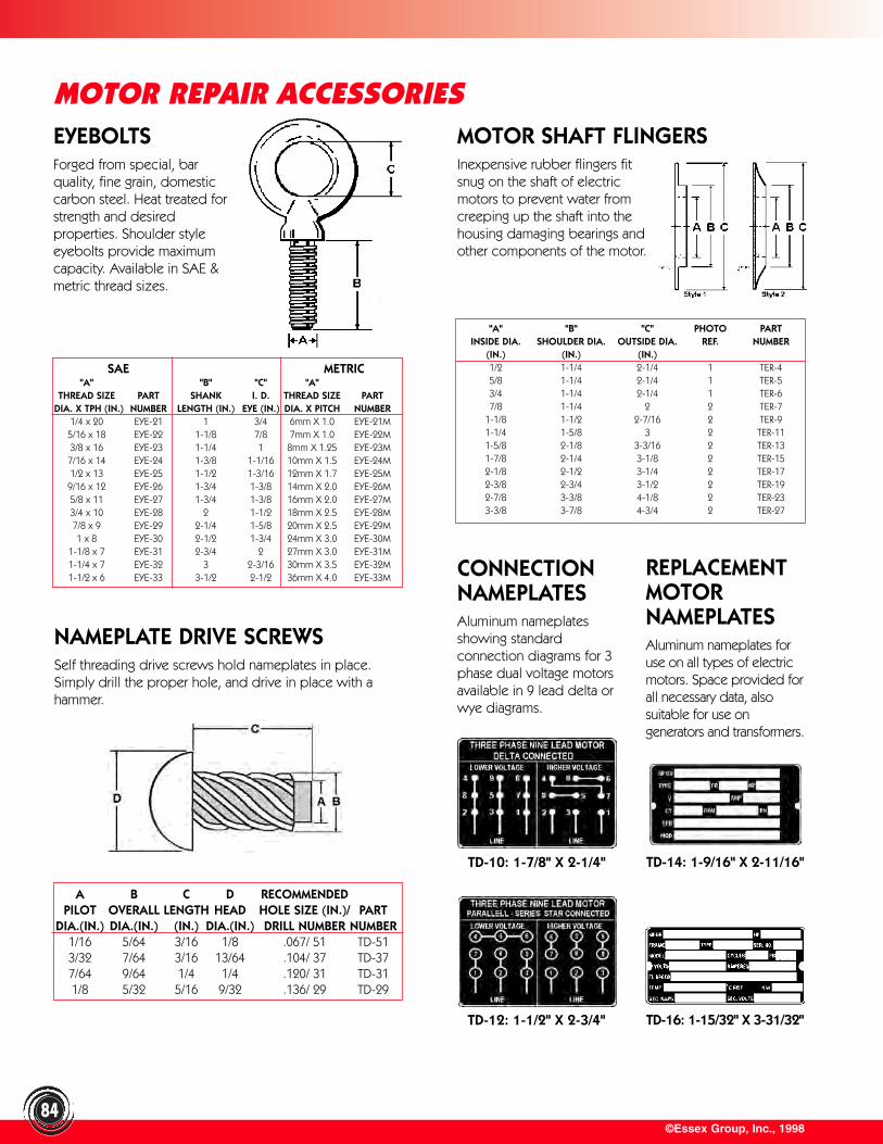
©Essex Group, Inc., 1998
MOTOR REPAIR ACCESSORIES
84
EYEBOLTSForged from special, barquality, fine grain, domesticcarbon steel. Heat treated forstrength and desiredproperties. Shoulder styleeyebolts provide maximumcapacity. Available in SAE &metric thread sizes.
SAE METRIC"A" "B" "C" "A"
THREAD SIZE PART SHANK I. D. THREAD SIZE PARTDIA. X TPH (IN.) NUMBER LENGTH (IN.) EYE (IN.) DIA. X PITCH NUMBER
1/4 x 20 EYE-21 1 3/4 6mm X 1.0 EYE-21M5/16 x 18 EYE-22 1-1/8 7/8 7mm X 1.0 EYE-22M3/8 x 16 EYE-23 1-1/4 1 8mm X 1.25 EYE-23M7/16 x 14 EYE-24 1-3/8 1-1/16 10mm X 1.5 EYE-24M1/2 x 13 EYE-25 1-1/2 1-3/16 12mm X 1.7 EYE-25M9/16 x 12 EYE-26 1-3/4 1-3/8 14mm X 2.0 EYE-26M5/8 x 11 EYE-27 1-3/4 1-3/8 16mm X 2.0 EYE-27M3/4 x 10 EYE-28 2 1-1/2 18mm X 2.5 EYE-28M7/8 x 9 EYE-29 2-1/4 1-5/8 20mm X 2.5 EYE-29M1 x 8 EYE-30 2-1/2 1-3/4 24mm X 3.0 EYE-30M
1-1/8 x 7 EYE-31 2-3/4 2 27mm X 3.0 EYE-31M1-1/4 x 7 EYE-32 3 2-3/16 30mm X 3.5 EYE-32M1-1/2 x 6 EYE-33 3-1/2 2-1/2 36mm X 4.0 EYE-33M
MOTOR SHAFT FLINGERSInexpensive rubber flingers fitsnug on the shaft of electricmotors to prevent water fromcreeping up the shaft into thehousing damaging bearings andother components of the motor.
"A" "B" "C" PHOTO PARTINSIDE DIA. SHOULDER DIA. OUTSIDE DIA. REF. NUMBER
(IN.) (IN.) (IN.)1/2 1-1/4 2-1/4 1 TER-45/8 1-1/4 2-1/4 1 TER-53/4 1-1/4 2-1/4 1 TER-67/8 1-1/4 2 2 TER-7
1-1/8 1-1/2 2-7/16 2 TER-91-1/4 1-5/8 3 2 TER-111-5/8 2-1/8 3-3/16 2 TER-131-7/8 2-1/4 3-1/8 2 TER-152-1/8 2-1/2 3-1/4 2 TER-172-3/8 2-3/4 3-1/2 2 TER-192-7/8 3-3/8 4-1/8 2 TER-233-3/8 3-7/8 4-3/4 2 TER-27
NAMEPLATE DRIVE SCREWSSelf threading drive screws hold nameplates in place.Simply drill the proper hole, and drive in place with ahammer.
A B C D RECOMMENDEDPILOT OVERALL LENGTH HEAD HOLE SIZE (IN.)/ PART
DIA.(IN.) DIA.(IN.) (IN.) DIA.(IN.) DRILL NUMBER NUMBER1/16 5/64 3/16 1/8 .067/ 51 TD-513/32 7/64 3/16 13/64 .104/ 37 TD-377/64 9/64 1/4 1/4 .120/ 31 TD-311/8 5/32 5/16 9/32 .136/ 29 TD-29
REPLACEMENTMOTORNAMEPLATESAluminum nameplates foruse on all types of electricmotors. Space provided forall necessary data, alsosuitable for use ongenerators and transformers.
CONNECTIONNAMEPLATESAluminum nameplatesshowing standardconnection diagrams for 3phase dual voltage motorsavailable in 9 lead delta orwye diagrams.
TD-10: 1-7/8" X 2-1/4" TD-14: 1-9/16" X 2-11/16"
TD-12: 1-1/2" X 2-3/4" TD-16: 1-15/32" X 3-31/32"
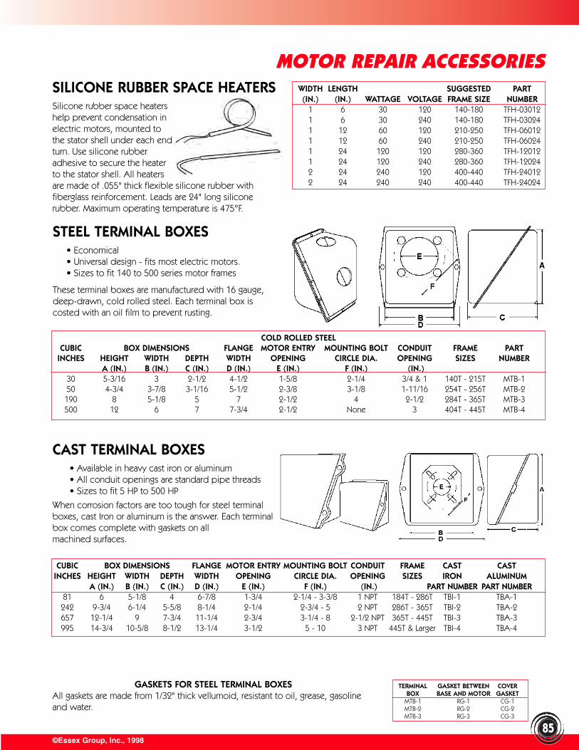
©Essex Group, Inc., 1998
MOTOR REPAIR ACCESSORIES
85
SILICONE RUBBER SPACE HEATERSSilicone rubber space heatershelp prevent condensation inelectric motors, mounted tothe stator shell under each endturn. Use silicone rubberadhesive to secure the heaterto the stator shell. All heatersare made of .055" thick flexible silicone rubber withfiberglass reinforcement. Leads are 24" long siliconerubber. Maximum operating temperature is 475°F.
WIDTH LENGTH SUGGESTED PART(IN.) (IN.) WATTAGE VOLTAGE FRAME SIZE NUMBER
1 6 30 120 140-180 TFH-030121 6 30 240 140-180 TFH-030241 12 60 120 210-250 TFH-060121 12 60 240 210-250 TFH-060241 24 120 120 280-360 TFH-120121 24 120 240 280-360 TFH-120242 24 240 120 400-440 TFH-240122 24 240 240 400-440 TFH-24024
STEEL TERMINAL BOXES• Economical• Universal design - fits most electric motors.• Sizes to fit 140 to 500 series motor frames
These terminal boxes are manufactured with 16 gauge,deep-drawn, cold rolled steel. Each terminal box iscosted with an oil film to prevent rusting.
COLD ROLLED STEELCUBIC BOX DIMENSIONS FLANGE MOTOR ENTRY MOUNTING BOLT CONDUIT FRAME PART
INCHES HEIGHT WIDTH DEPTH WIDTH OPENING CIRCLE DIA. OPENING SIZES NUMBERA (IN.) B (IN.) C (IN.) D (IN.) E (IN.) F (IN.) (IN.)
30 5-3/16 3 2-1/2 4-1/2 1-5/8 2-1/4 3/4 & 1 140T - 215T MTB-150 4-3/4 3-7/8 3-1/16 5-1/2 2-3/8 3-1/8 1-11/16 254T - 256T MTB-2190 8 5-1/8 5 7 2-1/2 4 2-1/2 284T - 365T MTB-3500 12 6 7 7-3/4 2-1/2 None 3 404T - 445T MTB-4
CAST TERMINAL BOXES• Available in heavy cast iron or aluminum• All conduit openings are standard pipe threads• Sizes to fit 5 HP to 500 HP
When corrosion factors are too tough for steel terminalboxes, cast Iron or aluminum is the answer. Each terminalbox comes complete with gaskets on all machined surfaces.
CUBIC BOX DIMENSIONS FLANGE MOTOR ENTRY MOUNTING BOLT CONDUIT FRAME CAST CASTINCHES HEIGHT WIDTH DEPTH WIDTH OPENING CIRCLE DIA. OPENING SIZES IRON ALUMINUM
A (IN.) B (IN.) C (IN.) D (IN.) E (IN.) F (IN.) (IN.) PART NUMBER PART NUMBER81 6 5-1/8 4 6-7/8 1-3/4 2-1/4 - 3-3/8 1 NPT 184T - 286T TBI-1 TBA-1242 9-3/4 6-1/4 5-5/8 8-1/4 2-1/4 2-3/4 - 5 2 NPT 286T - 365T TBI-2 TBA-2657 12-1/4 9 7-3/4 11-1/4 2-3/4 3-1/4 - 8 2-1/2 NPT 365T - 445T TBI-3 TBA-3995 14-3/4 10-5/8 8-1/2 13-1/4 3-1/2 5 - 10 3 NPT 445T & Larger TBI-4 TBA-4
GASKETS FOR STEEL TERMINAL BOXESAll gaskets are made from 1/32" thick vellumoid, resistant to oil, grease, gasolineand water.
TERMINAL GASKET BETWEEN COVERBOX BASE AND MOTOR GASKET
MTB-1 RG-1 CG-1MTB-2 RG-2 CG-2MTB-3 RG-3 CG-3
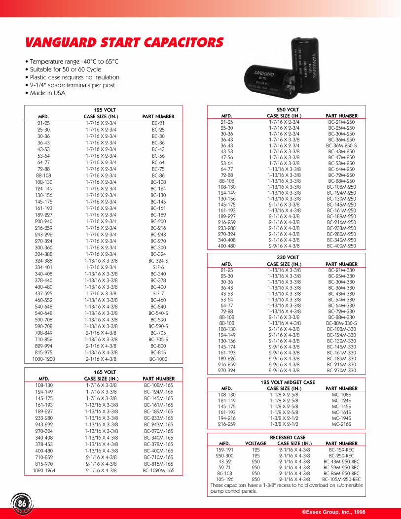
©Essex Group, Inc., 199886
VANGUARD START CAPACITORS• Temperature range -40°C to 65°C• Suitable for 50 or 60 Cycle• Plastic case requires no insulation• 2-1/4" spade terminals per post• Made in USA
165 VOLTMFD. CASE SIZE (IN.) PART NUMBER
108-130 1-7/16 X 3-3/8 BC-108M-165124-149 1-7/16 X 3-3/8 BC-124M-165145-175 1-7/16 X 3-3/8 BC-145M-165161-193 1-13/16 X 3-3/8 BC-161M-165189-227 1-13/16 X 3-3/8 BC-189M-165233-280 1-13/16 X 3-3/8 BC-233M-165243-292 1-13/16 X 3-3/8 BC-243M-165270-324 1-13/16 X 3-3/8 BC-270M-165340-408 1-13/16 X 4-3/8 BC-340M-165378-453 1-13/16 X 4-3/8 BC-378M-165400-480 1-13/16 X 4-3/8 BC-400M-165710-852 2-1/16 X 4-3/8 BC-710M-165815-970 2-1/16 X 4-3/8 BC-815M-165
1020-1264 2-1/16 X 4-3/8 BC-1020M-165
330 VOLTMFD. CASE SIZE (IN.) PART NUMBER21-25 1-13/16 X 3-3/8 BC-21M-33025-30 1-13/16 X 3-3/8 BC-25M-33030-36 1-13/16 X 3-3/8 BC-30M-33036-43 1-13/16 X 3-3/8 BC-36M-33043-53 1-13/16 X 3-3/8 BC-43M-33053-64 1-13/16 X 3-3/8 BC-54M-33064-77 1-13/16 X 3-3/8 BC-64M-33072-88 1-13/16 X 4-3/8 BC-72M-33088-108 2-1/16 X 3-3/8 BC-88M-33088-108 1-13/16 X 4-3/8 BC-88M-330-S108-130 2-1/16 X 4-3/8 BC-108M-330124-149 2-1/16 X 4-3/8 BC-124M-330130-156 2-1/16 X 4-3/8 BC-130M-330145-174 2-9/16 X 4-3/8 BC-145M-330161-193 2-9/16 X 4-3/8 BC-161M-330189-226 2-9/16 X 4-3/8 BC-189M-330216-259 2-9/16 X 4-3/8 BC-216M-330270-324 2-9/16 X 4-3/8 BC-270M-330
125 VOLT MIDGET CASEMFD. CASE SIZE (IN.) PART NUMBER
108-130 1-1/8 X 2-5/8 MC-108S124-149 1-1/8 X 2-5/8 MC-124S145-175 1-1/8 X 2-5/8 MC-145S161-193 1-1/8 X 2-5/8 MC-161S194-216 1-3/8 X 2-1/2 MC-194S216-259 1-3/8 X 2-1/2 MC-216S
RECESSED CASEMFD. VOLTAGE CASE SIZE (IN.) PART NUMBER
159-191 125 2-1/16 X 4-3/8 BC-159-REC250-300 125 2-1/16 X 4-3/8 BC-250-REC43-52 250 2-1/16 X 4-3/8 BC-43M-250-REC59-71 250 2-1/16 X 4-3/8 BC-59M-250-REC86-103 250 2-1/16 X 4-3/8 BC-86M-250-REC105-126 250 2-1/16 X 4-3/8 BC-105M-250-REC
These capacitors have a 1-3/8" recess to hold overload on submersiblepump control panels.
125 VOLTMFD. CASE SIZE (IN.) PART NUMBER21-25 1-7/16 X 2-3/4 BC-2125-30 1-7/16 X 2-3/4 BC-2530-36 1-7/16 X 2-3/4 BC-3036-43 1-7/16 X 2-3/4 BC-3643-53 1-7/16 X 2-3/4 BC-4353-64 1-7/16 X 2-3/4 BC-5664-77 1-7/16 X 2-3/4 BC-6472-88 1-7/16 X 2-3/4 BC-7588-108 1-7/16 X 2-3/4 BC-86108-130 1-7/16 X 2-3/4 BC-108124-149 1-7/16 X 2-3/4 BC-124130-156 1-7/16 X 2-3/4 BC-130145-175 1-7/16 X 2-3/4 BC-145161-193 1-7/16 X 2-3/4 BC-161189-227 1-7/16 X 2-3/4 BC-189200-240 1-7/16 X 2-3/4 BC-200216-259 1-7/16 X 2-3/4 BC-216243-292 1-7/16 X 2-3/4 BC-243270-324 1-7/16 X 2-3/4 BC-270300-360 1-7/16 X 2-3/4 BC-300324-388 1-7/16 X 2-3/4 BC-324324-388 1-13/16 X 3-3/8 BC-324-S334-401 1-7/16 X 2-3/4 SLF-6340-408 1-13/16 X 3-3/8 BC-340378-440 1-13/16 X 3-3/8 BC-378400-480 1-13/16 X 3-3/8 BC-400437-525 1-7/16 X 3-3/8 SLF-7460-552 1-13/16 X 3-3/8 BC-460540-648 1-13/16 X 4-3/8 BC-540540-648 1-13/16 X 3-3/8 BC-540-S590-708 1-13/16 X 4-3/8 BC-590590-708 1-13/16 X 3-3/8 BC-590-S708-849 2-1/16 X 4-3/8 BC-705710-852 1-13/16 X 3-3/8 BC-705-S829-994 2-1/16 X 4-3/8 BC-800815-975 1-13/16 X 4-3/8 BC-815
1000-1200 2-1/16 X 4-3/8 BC-1000
250 VOLTMFD. CASE SIZE (IN.) PART NUMBER21-25 1-7/16 X 2-3/4 BC-21M-25025-30 1-7/16 X 2-3/4 BC-25M-25030-36 1-7/16 X 2-3/4 BC-30M-25036-43 1-7/16 X 3-3/8 BC-36M-25036-43 1-7/16 X 2-3/4 BC-36M-250-S43-53 1-7/16 X 3-3/8 BC-43M-25047-56 1-7/16 X 3-3/8 BC-47M-25053-64 1-7/16 X 3-3/8 BC-53M-25064-77 1-13/16 X 3-3/8 BC-64M-25072-88 1-13/16 X 3-3/8 BC-72M-25088-108 1-13/16 X 3-3/8 BC-88M-250108-130 1-13/16 X 3-3/8 BC-108M-250124-149 1-13/16 X 3-3/8 BC-124M-250130-156 1-13/16 X 3-3/8 BC-130M-250145-175 2-1/16 X 3-3/8 BC-145M-250161-193 1-13/16 X 4-3/8 BC-161M-250189-227 2-1/16 X 4-3/8 BC-189M-250216-259 2-1/16 X 4-3/8 BC-216M-250233-280 2-1/16 X 4-3/8 BC-233M-250270-324 2-1/16 X 4-3/8 BC-280M-250340-408 2-1/16 X 4-3/8 BC-340M-250400-480 2-9/16 X 4-3/8 BC-400M-250
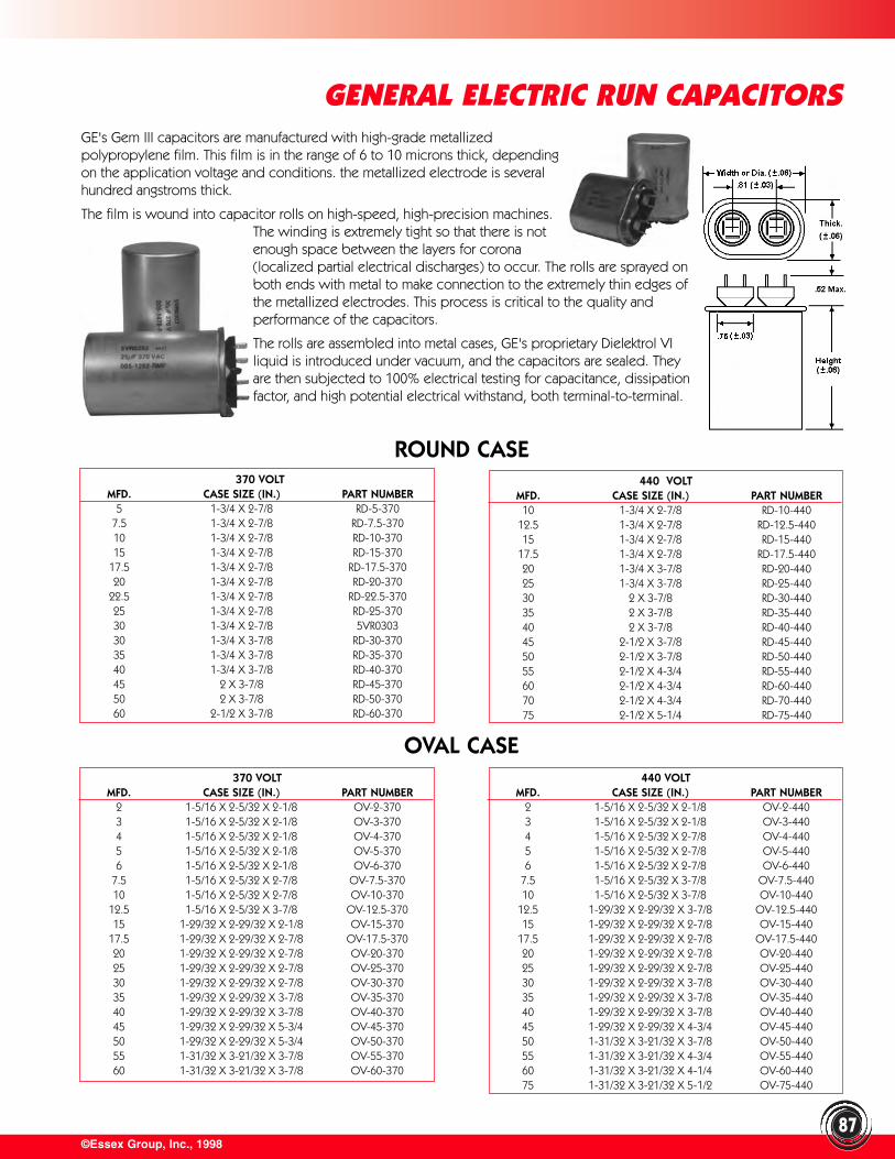
©Essex Group, Inc., 1998
GENERAL ELECTRIC RUN CAPACITORS
87
370 VOLTMFD. CASE SIZE (IN.) PART NUMBER
5 1-3/4 X 2-7/8 RD-5-3707.5 1-3/4 X 2-7/8 RD-7.5-37010 1-3/4 X 2-7/8 RD-10-37015 1-3/4 X 2-7/8 RD-15-370
17.5 1-3/4 X 2-7/8 RD-17.5-37020 1-3/4 X 2-7/8 RD-20-370
22.5 1-3/4 X 2-7/8 RD-22.5-37025 1-3/4 X 2-7/8 RD-25-37030 1-3/4 X 2-7/8 5VR030330 1-3/4 X 3-7/8 RD-30-37035 1-3/4 X 3-7/8 RD-35-37040 1-3/4 X 3-7/8 RD-40-37045 2 X 3-7/8 RD-45-37050 2 X 3-7/8 RD-50-37060 2-1/2 X 3-7/8 RD-60-370
440 VOLTMFD. CASE SIZE (IN.) PART NUMBER
10 1-3/4 X 2-7/8 RD-10-44012.5 1-3/4 X 2-7/8 RD-12.5-44015 1-3/4 X 2-7/8 RD-15-440
17.5 1-3/4 X 2-7/8 RD-17.5-44020 1-3/4 X 3-7/8 RD-20-44025 1-3/4 X 3-7/8 RD-25-44030 2 X 3-7/8 RD-30-44035 2 X 3-7/8 RD-35-44040 2 X 3-7/8 RD-40-44045 2-1/2 X 3-7/8 RD-45-44050 2-1/2 X 3-7/8 RD-50-44055 2-1/2 X 4-3/4 RD-55-44060 2-1/2 X 4-3/4 RD-60-44070 2-1/2 X 4-3/4 RD-70-44075 2-1/2 X 5-1/4 RD-75-440
370 VOLTMFD. CASE SIZE (IN.) PART NUMBER
2 1-5/16 X 2-5/32 X 2-1/8 OV-2-3703 1-5/16 X 2-5/32 X 2-1/8 OV-3-3704 1-5/16 X 2-5/32 X 2-1/8 OV-4-3705 1-5/16 X 2-5/32 X 2-1/8 OV-5-3706 1-5/16 X 2-5/32 X 2-1/8 OV-6-370
7.5 1-5/16 X 2-5/32 X 2-7/8 OV-7.5-37010 1-5/16 X 2-5/32 X 2-7/8 OV-10-370
12.5 1-5/16 X 2-5/32 X 3-7/8 OV-12.5-37015 1-29/32 X 2-29/32 X 2-1/8 OV-15-370
17.5 1-29/32 X 2-29/32 X 2-7/8 OV-17.5-37020 1-29/32 X 2-29/32 X 2-7/8 OV-20-37025 1-29/32 X 2-29/32 X 2-7/8 OV-25-37030 1-29/32 X 2-29/32 X 2-7/8 OV-30-37035 1-29/32 X 2-29/32 X 3-7/8 OV-35-37040 1-29/32 X 2-29/32 X 3-7/8 OV-40-37045 1-29/32 X 2-29/32 X 5-3/4 OV-45-37050 1-29/32 X 2-29/32 X 5-3/4 OV-50-37055 1-31/32 X 3-21/32 X 3-7/8 OV-55-37060 1-31/32 X 3-21/32 X 3-7/8 OV-60-370
440 VOLTMFD. CASE SIZE (IN.) PART NUMBER
2 1-5/16 X 2-5/32 X 2-1/8 OV-2-4403 1-5/16 X 2-5/32 X 2-1/8 OV-3-4404 1-5/16 X 2-5/32 X 2-7/8 OV-4-4405 1-5/16 X 2-5/32 X 2-7/8 OV-5-4406 1-5/16 X 2-5/32 X 2-7/8 OV-6-440
7.5 1-5/16 X 2-5/32 X 3-7/8 OV-7.5-44010 1-5/16 X 2-5/32 X 3-7/8 OV-10-440
12.5 1-29/32 X 2-29/32 X 3-7/8 OV-12.5-44015 1-29/32 X 2-29/32 X 2-7/8 OV-15-440
17.5 1-29/32 X 2-29/32 X 2-7/8 OV-17.5-44020 1-29/32 X 2-29/32 X 2-7/8 OV-20-44025 1-29/32 X 2-29/32 X 2-7/8 OV-25-44030 1-29/32 X 2-29/32 X 3-7/8 OV-30-44035 1-29/32 X 2-29/32 X 3-7/8 OV-35-44040 1-29/32 X 2-29/32 X 3-7/8 OV-40-44045 1-29/32 X 2-29/32 X 4-3/4 OV-45-44050 1-31/32 X 3-21/32 X 3-7/8 OV-50-44055 1-31/32 X 3-21/32 X 4-3/4 OV-55-44060 1-31/32 X 3-21/32 X 4-1/4 OV-60-44075 1-31/32 X 3-21/32 X 5-1/2 OV-75-440
GE's Gem III capacitors are manufactured with high-grade metallizedpolypropylene film. This film is in the range of 6 to 10 microns thick, dependingon the application voltage and conditions. the metallized electrode is severalhundred angstroms thick.
The film is wound into capacitor rolls on high-speed, high-precision machines.The winding is extremely tight so that there is notenough space between the layers for corona(localized partial electrical discharges) to occur. The rolls are sprayed onboth ends with metal to make connection to the extremely thin edges ofthe metallized electrodes. This process is critical to the quality andperformance of the capacitors.
The rolls are assembled into metal cases, GE's proprietary Dielektrol VIliquid is introduced under vacuum, and the capacitors are sealed. Theyare then subjected to 100% electrical testing for capacitance, dissipationfactor, and high potential electrical withstand, both terminal-to-terminal.
ROUND CASE
OVAL CASE
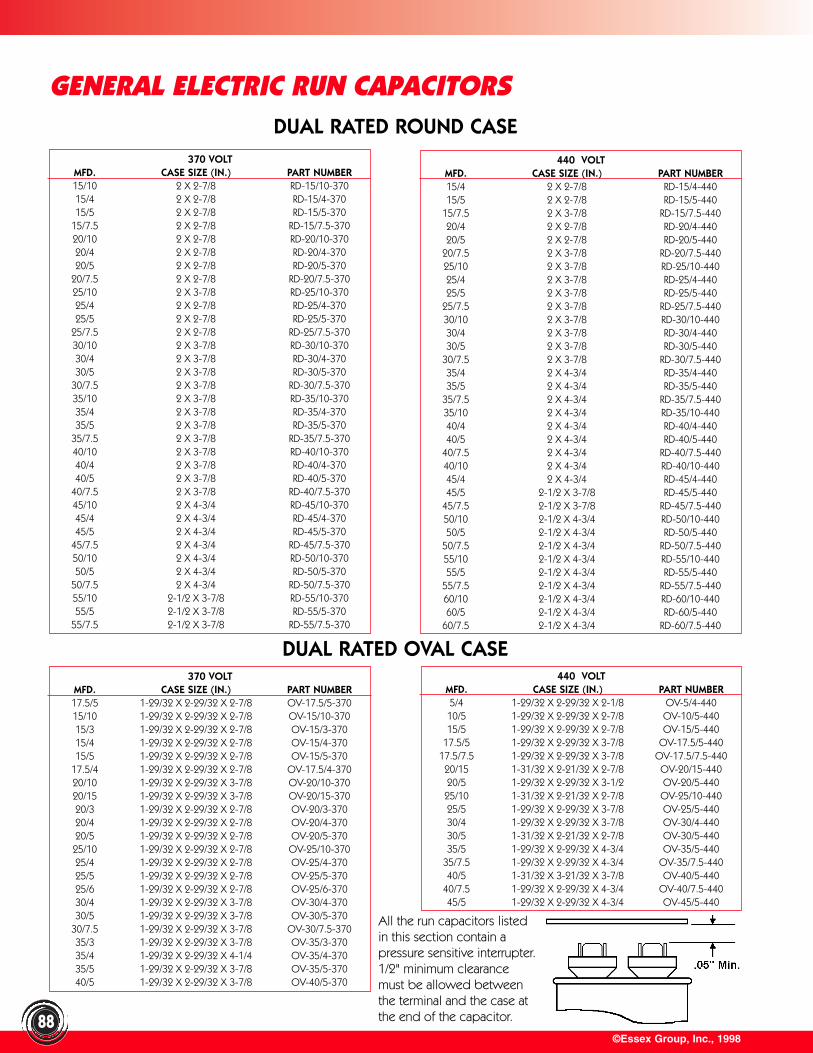
©Essex Group, Inc., 1998
GENERAL ELECTRIC RUN CAPACITORS
88
440 VOLTMFD. CASE SIZE (IN.) PART NUMBER15/4 2 X 2-7/8 RD-15/4-44015/5 2 X 2-7/8 RD-15/5-440
15/7.5 2 X 3-7/8 RD-15/7.5-44020/4 2 X 2-7/8 RD-20/4-44020/5 2 X 2-7/8 RD-20/5-440
20/7.5 2 X 3-7/8 RD-20/7.5-44025/10 2 X 3-7/8 RD-25/10-44025/4 2 X 3-7/8 RD-25/4-44025/5 2 X 3-7/8 RD-25/5-440
25/7.5 2 X 3-7/8 RD-25/7.5-44030/10 2 X 3-7/8 RD-30/10-44030/4 2 X 3-7/8 RD-30/4-44030/5 2 X 3-7/8 RD-30/5-440
30/7.5 2 X 3-7/8 RD-30/7.5-44035/4 2 X 4-3/4 RD-35/4-44035/5 2 X 4-3/4 RD-35/5-440
35/7.5 2 X 4-3/4 RD-35/7.5-44035/10 2 X 4-3/4 RD-35/10-44040/4 2 X 4-3/4 RD-40/4-44040/5 2 X 4-3/4 RD-40/5-440
40/7.5 2 X 4-3/4 RD-40/7.5-44040/10 2 X 4-3/4 RD-40/10-44045/4 2 X 4-3/4 RD-45/4-44045/5 2-1/2 X 3-7/8 RD-45/5-440
45/7.5 2-1/2 X 3-7/8 RD-45/7.5-44050/10 2-1/2 X 4-3/4 RD-50/10-44050/5 2-1/2 X 4-3/4 RD-50/5-440
50/7.5 2-1/2 X 4-3/4 RD-50/7.5-44055/10 2-1/2 X 4-3/4 RD-55/10-44055/5 2-1/2 X 4-3/4 RD-55/5-440
55/7.5 2-1/2 X 4-3/4 RD-55/7.5-44060/10 2-1/2 X 4-3/4 RD-60/10-44060/5 2-1/2 X 4-3/4 RD-60/5-440
60/7.5 2-1/2 X 4-3/4 RD-60/7.5-440
DUAL RATED ROUND CASE
DUAL RATED OVAL CASE440 VOLT
MFD. CASE SIZE (IN.) PART NUMBER5/4 1-29/32 X 2-29/32 X 2-1/8 OV-5/4-440
10/5 1-29/32 X 2-29/32 X 2-7/8 OV-10/5-44015/5 1-29/32 X 2-29/32 X 2-7/8 OV-15/5-440
17.5/5 1-29/32 X 2-29/32 X 3-7/8 OV-17.5/5-44017.5/7.5 1-29/32 X 2-29/32 X 3-7/8 OV-17.5/7.5-44020/15 1-31/32 X 2-21/32 X 2-7/8 OV-20/15-44020/5 1-29/32 X 2-29/32 X 3-1/2 OV-20/5-44025/10 1-31/32 X 2-21/32 X 2-7/8 OV-25/10-44025/5 1-29/32 X 2-29/32 X 3-7/8 OV-25/5-44030/4 1-29/32 X 2-29/32 X 3-7/8 OV-30/4-44030/5 1-31/32 X 2-21/32 X 2-7/8 OV-30/5-44035/5 1-29/32 X 2-29/32 X 4-3/4 OV-35/5-440
35/7.5 1-29/32 X 2-29/32 X 4-3/4 OV-35/7.5-44040/5 1-31/32 X 3-21/32 X 3-7/8 OV-40/5-440
40/7.5 1-29/32 X 2-29/32 X 4-3/4 OV-40/7.5-44045/5 1-29/32 X 2-29/32 X 4-3/4 OV-45/5-440
All the run capacitors listedin this section contain apressure sensitive interrupter.1/2" minimum clearancemust be allowed betweenthe terminal and the case atthe end of the capacitor.
370 VOLTMFD. CASE SIZE (IN.) PART NUMBER15/10 2 X 2-7/8 RD-15/10-37015/4 2 X 2-7/8 RD-15/4-37015/5 2 X 2-7/8 RD-15/5-370
15/7.5 2 X 2-7/8 RD-15/7.5-37020/10 2 X 2-7/8 RD-20/10-37020/4 2 X 2-7/8 RD-20/4-37020/5 2 X 2-7/8 RD-20/5-370
20/7.5 2 X 2-7/8 RD-20/7.5-37025/10 2 X 3-7/8 RD-25/10-37025/4 2 X 2-7/8 RD-25/4-37025/5 2 X 2-7/8 RD-25/5-370
25/7.5 2 X 2-7/8 RD-25/7.5-37030/10 2 X 3-7/8 RD-30/10-37030/4 2 X 3-7/8 RD-30/4-37030/5 2 X 3-7/8 RD-30/5-370
30/7.5 2 X 3-7/8 RD-30/7.5-37035/10 2 X 3-7/8 RD-35/10-37035/4 2 X 3-7/8 RD-35/4-37035/5 2 X 3-7/8 RD-35/5-370
35/7.5 2 X 3-7/8 RD-35/7.5-37040/10 2 X 3-7/8 RD-40/10-37040/4 2 X 3-7/8 RD-40/4-37040/5 2 X 3-7/8 RD-40/5-370
40/7.5 2 X 3-7/8 RD-40/7.5-37045/10 2 X 4-3/4 RD-45/10-37045/4 2 X 4-3/4 RD-45/4-37045/5 2 X 4-3/4 RD-45/5-370
45/7.5 2 X 4-3/4 RD-45/7.5-37050/10 2 X 4-3/4 RD-50/10-37050/5 2 X 4-3/4 RD-50/5-370
50/7.5 2 X 4-3/4 RD-50/7.5-37055/10 2-1/2 X 3-7/8 RD-55/10-37055/5 2-1/2 X 3-7/8 RD-55/5-370
55/7.5 2-1/2 X 3-7/8 RD-55/7.5-370
370 VOLTMFD. CASE SIZE (IN.) PART NUMBER17.5/5 1-29/32 X 2-29/32 X 2-7/8 OV-17.5/5-37015/10 1-29/32 X 2-29/32 X 2-7/8 OV-15/10-37015/3 1-29/32 X 2-29/32 X 2-7/8 OV-15/3-37015/4 1-29/32 X 2-29/32 X 2-7/8 OV-15/4-37015/5 1-29/32 X 2-29/32 X 2-7/8 OV-15/5-370
17.5/4 1-29/32 X 2-29/32 X 2-7/8 OV-17.5/4-37020/10 1-29/32 X 2-29/32 X 3-7/8 OV-20/10-37020/15 1-29/32 X 2-29/32 X 3-7/8 OV-20/15-37020/3 1-29/32 X 2-29/32 X 2-7/8 OV-20/3-37020/4 1-29/32 X 2-29/32 X 2-7/8 OV-20/4-37020/5 1-29/32 X 2-29/32 X 2-7/8 OV-20/5-37025/10 1-29/32 X 2-29/32 X 2-7/8 OV-25/10-37025/4 1-29/32 X 2-29/32 X 2-7/8 OV-25/4-37025/5 1-29/32 X 2-29/32 X 2-7/8 OV-25/5-37025/6 1-29/32 X 2-29/32 X 2-7/8 OV-25/6-37030/4 1-29/32 X 2-29/32 X 3-7/8 OV-30/4-37030/5 1-29/32 X 2-29/32 X 3-7/8 OV-30/5-370
30/7.5 1-29/32 X 2-29/32 X 3-7/8 OV-30/7.5-37035/3 1-29/32 X 2-29/32 X 3-7/8 OV-35/3-37035/4 1-29/32 X 2-29/32 X 4-1/4 OV-35/4-37035/5 1-29/32 X 2-29/32 X 3-7/8 OV-35/5-37040/5 1-29/32 X 2-29/32 X 3-7/8 OV-40/5-370
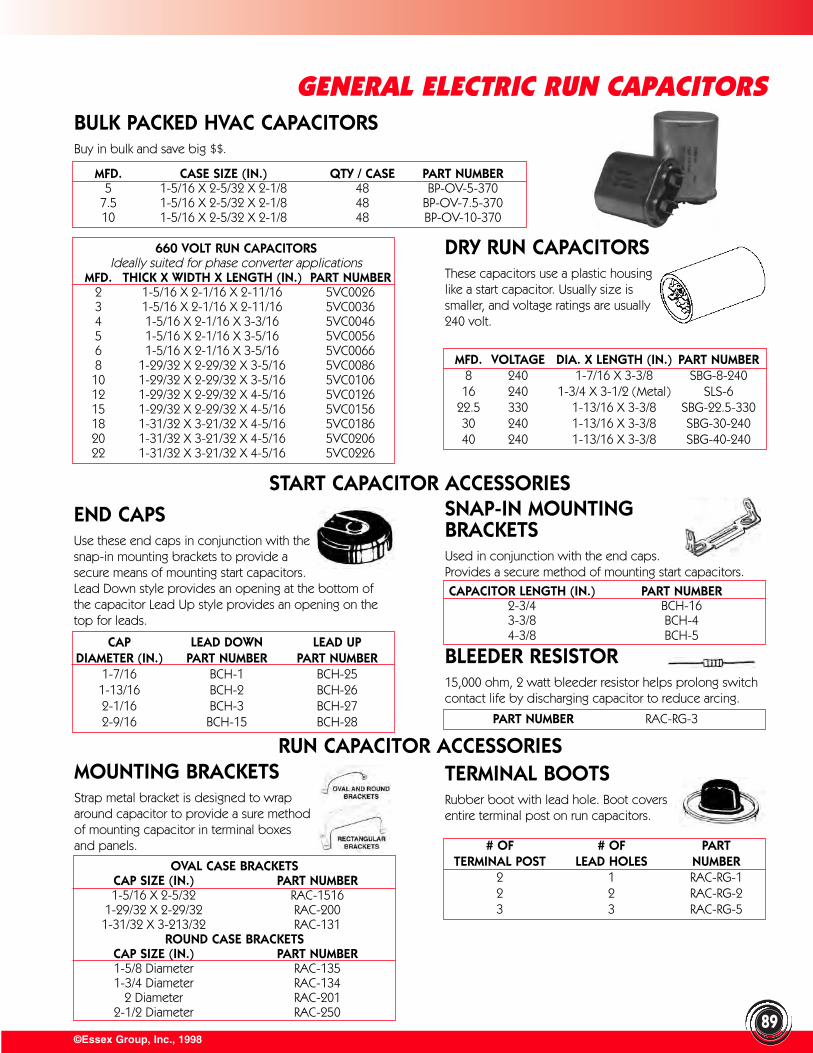
©Essex Group, Inc., 199889
GENERAL ELECTRIC RUN CAPACITORSBULK PACKED HVAC CAPACITORSBuy in bulk and save big $$.
MFD. CASE SIZE (IN.) QTY / CASE PART NUMBER5 1-5/16 X 2-5/32 X 2-1/8 48 BP-OV-5-370
7.5 1-5/16 X 2-5/32 X 2-1/8 48 BP-OV-7.5-37010 1-5/16 X 2-5/32 X 2-1/8 48 BP-OV-10-370
DRY RUN CAPACITORSThese capacitors use a plastic housinglike a start capacitor. Usually size issmaller, and voltage ratings are usually240 volt.
MFD. VOLTAGE DIA. X LENGTH (IN.) PART NUMBER8 240 1-7/16 X 3-3/8 SBG-8-24016 240 1-3/4 X 3-1/2 (Metal) SLS-6
22.5 330 1-13/16 X 3-3/8 SBG-22.5-33030 240 1-13/16 X 3-3/8 SBG-30-24040 240 1-13/16 X 3-3/8 SBG-40-240
START CAPACITOR ACCESSORIES
END CAPSUse these end caps in conjunction with thesnap-in mounting brackets to provide asecure means of mounting start capacitors.Lead Down style provides an opening at the bottom ofthe capacitor Lead Up style provides an opening on thetop for leads.
CAP LEAD DOWN LEAD UPDIAMETER (IN.) PART NUMBER PART NUMBER
1-7/16 BCH-1 BCH-251-13/16 BCH-2 BCH-262-1/16 BCH-3 BCH-272-9/16 BCH-15 BCH-28
SNAP-IN MOUNTING BRACKETSUsed in conjunction with the end caps. Provides a secure method of mounting start capacitors.
CAPACITOR LENGTH (IN.) PART NUMBER2-3/4 BCH-163-3/8 BCH-44-3/8 BCH-5
MOUNTING BRACKETSStrap metal bracket is designed to wraparound capacitor to provide a sure methodof mounting capacitor in terminal boxes and panels.
OVAL CASE BRACKETSCAP SIZE (IN.) PART NUMBER1-5/16 X 2-5/32 RAC-1516
1-29/32 X 2-29/32 RAC-2001-31/32 X 3-213/32 RAC-131
ROUND CASE BRACKETSCAP SIZE (IN.) PART NUMBER1-5/8 Diameter RAC-1351-3/4 Diameter RAC-134
2 Diameter RAC-2012-1/2 Diameter RAC-250
TERMINAL BOOTSRubber boot with lead hole. Boot coversentire terminal post on run capacitors.
# OF # OF PARTTERMINAL POST LEAD HOLES NUMBER
2 1 RAC-RG-12 2 RAC-RG-23 3 RAC-RG-5
660 VOLT RUN CAPACITORSIdeally suited for phase converter applications
MFD. THICK X WIDTH X LENGTH (IN.) PART NUMBER2 1-5/16 X 2-1/16 X 2-11/16 5VC00263 1-5/16 X 2-1/16 X 2-11/16 5VC00364 1-5/16 X 2-1/16 X 3-3/16 5VC00465 1-5/16 X 2-1/16 X 3-5/16 5VC00566 1-5/16 X 2-1/16 X 3-5/16 5VC00668 1-29/32 X 2-29/32 X 3-5/16 5VC008610 1-29/32 X 2-29/32 X 3-5/16 5VC010612 1-29/32 X 2-29/32 X 4-5/16 5VC012615 1-29/32 X 2-29/32 X 4-5/16 5VC015618 1-31/32 X 3-21/32 X 4-5/16 5VC018620 1-31/32 X 3-21/32 X 4-5/16 5VC020622 1-31/32 X 3-21/32 X 4-5/16 5VC0226
RUN CAPACITOR ACCESSORIES
BLEEDER RESISTOR15,000 ohm, 2 watt bleeder resistor helps prolong switchcontact life by discharging capacitor to reduce arcing.
PART NUMBER RAC-RG-3
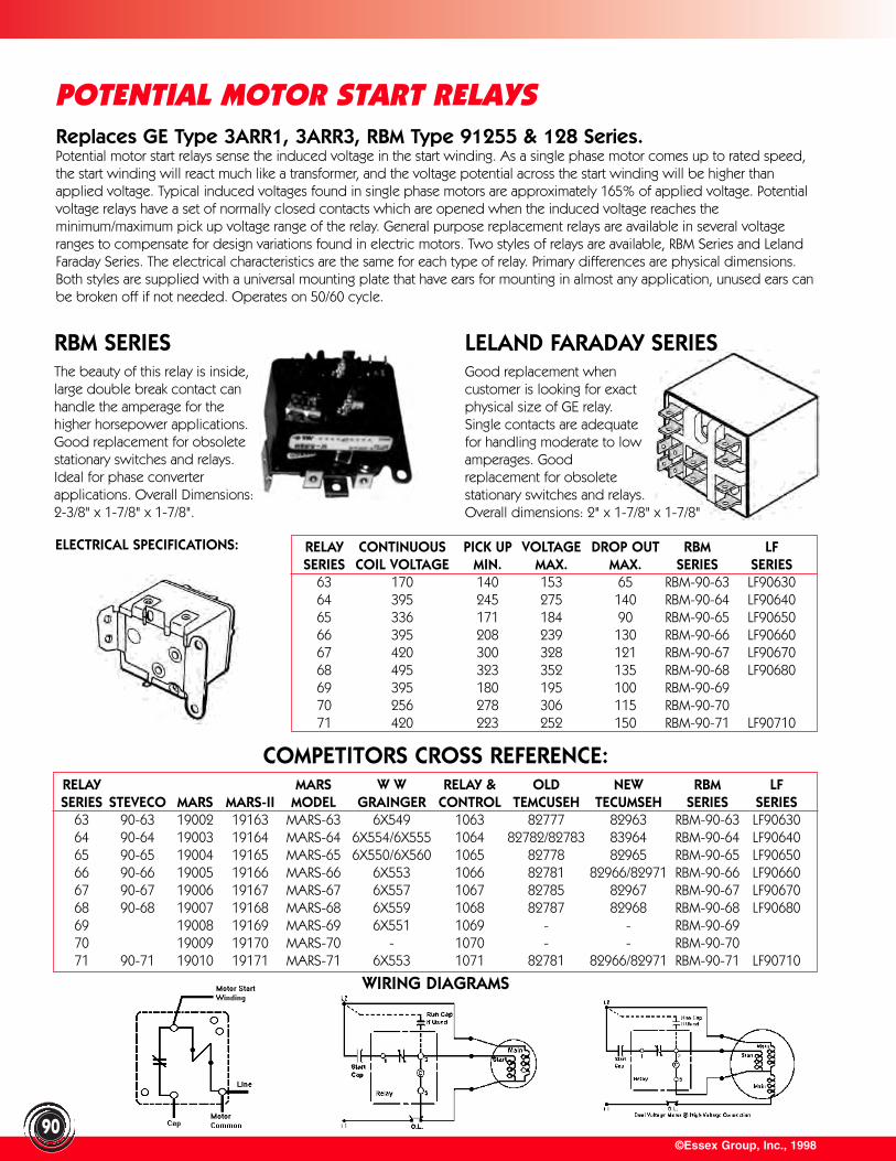
©Essex Group, Inc., 199890
POTENTIAL MOTOR START RELAYSReplaces GE Type 3ARR1, 3ARR3, RBM Type 91255 & 128 Series.Potential motor start relays sense the induced voltage in the start winding. As a single phase motor comes up to rated speed,the start winding will react much like a transformer, and the voltage potential across the start winding will be higher thanapplied voltage. Typical induced voltages found in single phase motors are approximately 165% of applied voltage. Potentialvoltage relays have a set of normally closed contacts which are opened when the induced voltage reaches theminimum/maximum pick up voltage range of the relay. General purpose replacement relays are available in several voltageranges to compensate for design variations found in electric motors. Two styles of relays are available, RBM Series and LelandFaraday Series. The electrical characteristics are the same for each type of relay. Primary differences are physical dimensions.Both styles are supplied with a universal mounting plate that have ears for mounting in almost any application, unused ears canbe broken off if not needed. Operates on 50/60 cycle.
RBM SERIESThe beauty of this relay is inside,large double break contact canhandle the amperage for thehigher horsepower applications.Good replacement for obsoletestationary switches and relays.Ideal for phase converterapplications. Overall Dimensions:2-3/8" x 1-7/8" x 1-7/8".
ELECTRICAL SPECIFICATIONS: RELAY CONTINUOUS PICK UP VOLTAGE DROP OUT RBM LFSERIES COIL VOLTAGE MIN. MAX. MAX. SERIES SERIES
63 170 140 153 65 RBM-90-63 LF9063064 395 245 275 140 RBM-90-64 LF9064065 336 171 184 90 RBM-90-65 LF9065066 395 208 239 130 RBM-90-66 LF9066067 420 300 328 121 RBM-90-67 LF9067068 495 323 352 135 RBM-90-68 LF9068069 395 180 195 100 RBM-90-6970 256 278 306 115 RBM-90-7071 420 223 252 150 RBM-90-71 LF90710
COMPETITORS CROSS REFERENCE:RELAY MARS W W RELAY & OLD NEW RBM LFSERIES STEVECO MARS MARS-II MODEL GRAINGER CONTROL TEMCUSEH TECUMSEH SERIES SERIES
63 90-63 19002 19163 MARS-63 6X549 1063 82777 82963 RBM-90-63 LF9063064 90-64 19003 19164 MARS-64 6X554/6X555 1064 82782/82783 83964 RBM-90-64 LF9064065 90-65 19004 19165 MARS-65 6X550/6X560 1065 82778 82965 RBM-90-65 LF9065066 90-66 19005 19166 MARS-66 6X553 1066 82781 82966/82971 RBM-90-66 LF9066067 90-67 19006 19167 MARS-67 6X557 1067 82785 82967 RBM-90-67 LF9067068 90-68 19007 19168 MARS-68 6X559 1068 82787 82968 RBM-90-68 LF9068069 19008 19169 MARS-69 6X551 1069 - - RBM-90-6970 19009 19170 MARS-70 - 1070 - - RBM-90-7071 90-71 19010 19171 MARS-71 6X553 1071 82781 82966/82971 RBM-90-71 LF90710
WIRING DIAGRAMS
LELAND FARADAY SERIESGood replacement when customer is looking for exact physical size of GE relay. Single contacts are adequate for handling moderate to low amperages. Good replacement for obsolete stationary switches and relays. Overall dimensions: 2" x 1-7/8" x 1-7/8"
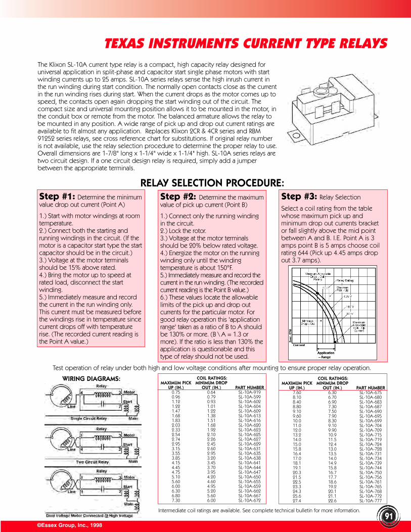
COIL RATINGS:MAXIMUM PICK MINIMUM DROP
UP (IN.) OUT (IN.) PART NUMBER7.60 6.30 SL-10A-6758.10 6.70 SL-10A-6808.40 6.90 SL-10A-6838.80 7.30 SL-10A-6879.10 7.50 SL-10A-6909.60 7.90 SL-10A-69510.0 8.30 SL-10A-69911.0 9.10 SL-10A-70412.0 9.90 SL-10A-70913.2 10.9 SL-10A-71514.0 11.5 SL-10A-71915.0 12.4 SL-10A-72415.8 13.0 SL-10A-72816.4 13.5 SL-10A-73117.0 14.0 SL-10A-73418.1 14.9 SL-10A-73919.1 15.8 SL-10A-74420.3 16.7 SL-10A-75021.5 17.7 SL-10A-75622.5 18.6 SL-10A-76123.3 19.2 SL-10A-76524.3 20.1 SL-10A-76825.6 21.1 SL-10A-77227.4 22.6 SL-10A-777
©Essex Group, Inc., 199891
TEXAS INSTRUMENTS CURRENT TYPE RELAYSThe Klixon SL-10A current type relay is a compact, high capacity relay designed foruniversal application in split-phase and capacitor start single phase motors with startwinding currents up to 25 amps. SL-10A series relays sense the high inrush current inthe run winding during start condition. The normally open contacts close as the currentin the run winding rises during start. When the current drops as the motor comes up tospeed, the contacts open again dropping the start winding out of the circuit. Thecompact size and universal mounting position allows it to be mounted in the motor, inthe conduit box or remote from the motor. The balanced armature allows the relay tobe mounted in any position. A wide range of pick up and drop out current ratings areavailable to fit almost any application. Replaces Klixon 2CR & 4CR series and RBM91252 series relays, see cross reference chart for substitutions. If original relay numberis not available, use the relay selection procedure to determine the proper relay to use.Overall dimensions are 1-7/8" long x 1-1/4" wide x 1-1/4" high. SL-10A series relays aretwo circuit design. If a one circuit design relay is required, simply add a jumperbetween the appropriate terminals.
RELAY SELECTION PROCEDURE:Step #1: Determine the minimumvalue drop out current (Point A)
1.) Start with motor windings at roomtemperature.2.) Connect both the starting andrunning windings in the circuit. (If themotor is a capacitor start type the startcapacitor should be in the circuit.)3.) Voltage at the motor terminalsshould be 15% above rated.4.) Bring the motor up to speed atrated load, disconnect the startwinding.5.) Immediately measure and recordthe current in the run winding only.This current must be measured beforethe windings rise in temperature sincecurrent drops off with temperaturerise. (The recorded current reading isthe Point A value.)
Step #2: Determine the maximumvalue of pick up current (Point B)
1.) Connect only the running windingin the circuit. 2.) Lock the rotor.3.) Voltage at the motor terminalsshould be 20% below rated voltage.4.) Energize the motor on the runningwinding only until the windingtemperature is about 150°F.5.) Immediately measure and record thecurrent in the run winding. (The recordedcurrent reading is the Point B value.)6.) These values locate the allowablelimits of the pick up and drop outcurrents for the particular motor. Forgood relay operation this 'applicationrange' taken as a ratio of B to A shouldbe 130% or more. (B \ A = 1.3 ormore). If the ratio is less than 130% theapplication is questionable and thistype of relay should not be used.
Step #3: Relay Selection
Select a coil rating from the tablewhose maximum pick up andminimum drop out currents bracketor fall slightly above the mid pointbetween A and B. I.E. Point A is 3amps point B is 5 amps choose coilrating 644 (Pick up 4.45 amps dropout 3.7 amps).
Test operation of relay under both high and low voltage conditions after mounting to ensure proper relay operation.
WIRING DIAGRAMS: COIL RATINGS:MAXIMUM PICK MINIMUM DROP
UP (IN.) OUT (IN.) PART NUMBER0.75 0.64 SL-10A-9190.96 0.79 SL-10A-5991.12 0.93 SL-10A-6021.22 1.01 SL-10A-6041.47 1.22 SL-10A-6091.68 1.38 SL-10A-6131.83 1.51 SL-10A-6162.03 1.68 SL-10A-6202.33 1.92 SL-10A-6232.54 2.10 SL-10A-6252.74 2.26 SL-10A-6272.95 2.45 SL-10A-6293.15 2.60 SL-10A-6313.55 2.95 SL-10A-6353.85 3.20 SL-10A-6384.15 3.45 SL-10A-6414.45 3.70 SL-10A-6444.75 3.95 SL-10A-6475.10 4.20 SL-10A-6505.60 4.60 SL-10A-6556.00 4.95 SL-10A-6596.30 5.20 SL-10A-6626.80 5.60 SL-10A-6677.30 6.00 SL-10A-672
Intermediate coil ratings are available. See complete technical bulletin for more information.
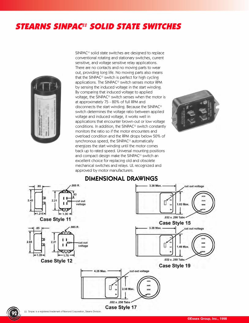
©Essex Group, Inc., 199892
STEARNS SINPAC‡‡ SOLID STATE SWITCHES
SINPAC‡‡ solid state switches are designed to replaceconventional rotating and stationary switches, currentsensitive, and voltage sensitive relay applications.There are no contacts and no moving parts to wearout, providing long life. No moving parts also meansthat the SINPAC‡‡ switch is perfect for high cyclingapplications. The SINPAC‡‡ switch senses motor RPMby sensing the induced voltage in the start winding.By comparing that induced voltage to appliedvoltage, the SINPAC‡‡ switch senses when the motor isat approximately 75 - 80% of full RPM anddisconnects the start winding. Because the SINPAC‡‡
switch determines the voltage ratio between appliedvoltage and induced voltage, it works well inapplications that encounter brown-out or low voltageconditions. In addition, the SINPAC‡‡ switch constantlymonitors the ratio so if the motor encounters andoverload condition and the RPM drops below 50% ofsynchronous speed, the SINPAC‡‡ automaticallyenergizes the start winding until the motor comesback up to rated speed. Universal mounting positionsand compact design make the SINPAC‡‡ switch anexcellent choice for replacing old and obsoletemechanical switches and relays. UL recognized andapproved by motor manufacturers.
DIMENSIONAL DRAWINGS
‡‡ Sinpac is a registered trademark of Rexnord Corporation, Stearns Division.
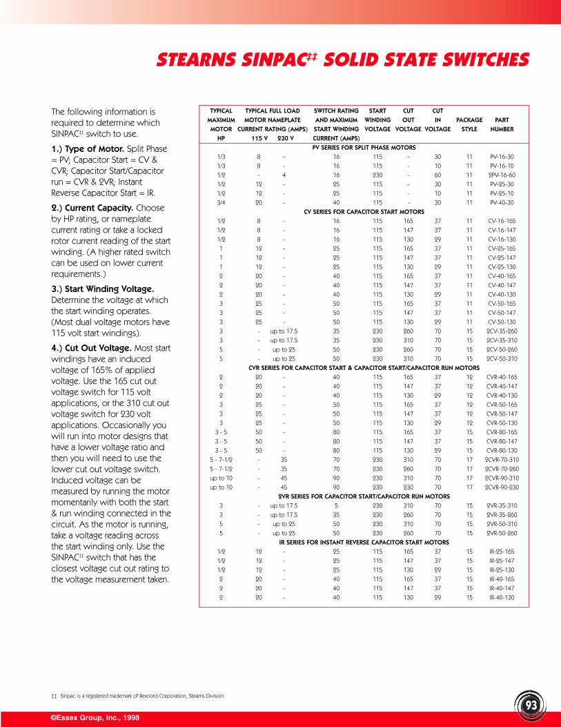
©Essex Group, Inc., 1998
STEARNS SINPAC‡‡ SOLID STATE SWITCHES
93
The following information isrequired to determine whichSINPAC‡‡ switch to use.
1.) Type of Motor. Split Phase= PV; Capacitor Start = CV &CVR; Capacitor Start/Capacitorrun = CVR & 2VR; InstantReverse Capacitor Start = IR.
2.) Current Capacity. Chooseby HP rating, or nameplatecurrent rating or take a lockedrotor current reading of the startwinding. (A higher rated switchcan be used on lower currentrequirements.)
3.) Start Winding Voltage.Determine the voltage at whichthe start winding operates.(Most dual voltage motors have115 volt start windings).
4.) Cut Out Voltage. Most startwindings have an inducedvoltage of 165% of appliedvoltage. Use the 165 cut outvoltage switch for 115 voltapplications, or the 310 cut outvoltage switch for 230 voltapplications. Occasionally youwill run into motor designs thathave a lower voltage ratio andthen you will need to use thelower cut out voltage switch.Induced voltage can bemeasured by running the motormomentarily with both the start& run winding connected in thecircuit. As the motor is running,take a voltage reading acrossthe start winding only. Use theSINPAC‡‡ switch that has theclosest voltage cut out rating tothe voltage measurement taken.
TYPICAL TYPICAL FULL LOAD SWITCH RATING START CUT CUTMAXIMUM MOTOR NAMEPLATE AND MAXIMUM WINDING OUT IN PACKAGE PARTMOTOR CURRENT RATING (AMPS) START WINDING VOLTAGE VOLTAGE VOLTAGE STYLE NUMBER
HP 115 V 230 V CURRENT (AMPS)PV SERIES FOR SPLIT PHASE MOTORS
1/3 8 - 16 115 - 30 11 PV-16-30
1/3 8 - 16 115 - 10 11 PV-16-10
1/2 - 4 16 230 - 60 11 2PV-16-60
1/2 12 - 25 115 - 30 11 PV-25-30
1/2 12 - 25 115 - 10 11 PV-25-10
3/4 20 - 40 115 - 30 11 PV-40-30
CV SERIES FOR CAPACITOR START MOTORS1/2 8 - 16 115 165 37 11 CV-16-165
1/2 8 - 16 115 147 37 11 CV-16-147
1/2 8 - 16 115 130 29 11 CV-16-130
1 12 - 25 115 165 37 11 CV-25-165
1 12 - 25 115 147 37 11 CV-25-147
1 12 - 25 115 130 29 11 CV-25-130
2 20 - 40 115 165 37 11 CV-40-165
2 20 - 40 115 147 37 11 CV-40-147
2 20 - 40 115 130 29 11 CV-40-130
3 25 - 50 115 165 37 11 CV-50-165
3 25 - 50 115 147 37 11 CV-50-147
3 25 - 50 115 130 29 11 CV-50-130
3 - up to 17.5 35 230 260 70 15 2CV-35-260
3 - up to 17.5 35 230 310 70 15 2CV-35-310
5 - up to 25 50 230 260 70 15 2CV-50-260
5 - up to 25 50 230 310 70 15 2CV-50-310
CVR SERIES FOR CAPACITOR START & CAPACITOR START/CAPACITOR RUN MOTORS2 20 - 40 115 165 37 12 CVR-40-165
2 20 - 40 115 147 37 12 CVR-40-147
2 20 - 40 115 130 29 12 CVR-40-130
3 25 - 50 115 165 37 12 CVR-50-165
3 25 - 50 115 147 37 12 CVR-50-147
3 25 - 50 115 130 29 12 CVR-50-130
3 - 5 50 - 80 115 165 37 15 CVR-80-165
3 - 5 50 - 80 115 147 37 15 CVR-80-147
3 - 5 50 - 80 115 130 29 15 CVR-80-130
5 - 7-1/2 - 35 70 230 310 70 17 2CVR-70-310
5 - 7-1/2 - 35 70 230 260 70 17 2CVR-70-260
up to 10 - 45 90 230 310 70 17 2CVR-90-310
up to 10 - 45 90 230 230 70 17 2CVR-90-230
2VR SERIES FOR CAPACITOR START/CAPACITOR RUN MOTORS3 - up to 17.5 5 230 310 70 15 2VR-35-310
3 - up to 17.5 35 230 260 70 15 2VR-35-260
5 - up to 25 50 230 310 70 15 2VR-50-310
5 - up to 25 50 230 260 70 15 2VR-50-260
IR SERIES FOR INSTANT REVERSE CAPACITOR START MOTORS1/2 12 - 25 115 165 37 15 IR-25-165
1/2 12 - 25 115 147 37 15 IR-25-147
1/2 12 - 25 115 130 29 15 IR-25-130
2 20 - 40 115 165 37 15 IR-40-165
2 20 - 40 115 147 37 15 IR-40-147
2 20 - 40 115 130 29 15 IR-40-130
‡‡ Sinpac is a registered trademark of Rexnord Corporation, Stearns Division.
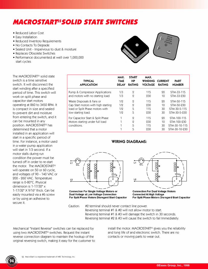
©Essex Group, Inc., 199894
MACROSTART§§SOLID STATE SWITCHES
The MACROSTART§§ solid stateswitch is a time sensitiveswitch. It will disconnect thestart winding after a specifiedperiod of time. This switch willwork on split phase andcapacitor start motors operating at 860 to 3450 RPM. Itis compact in size and sealedto prevent dirt and moisturefrom entering the switch, and itcan be mounted in anyposition. MACROSTART§§ hasdetermined that a motorinstalled in an application willstart in a specific period oftime. For instance, a motor usedin a water pump applicationwill start in 1/3 second. If amotor stalls during runcondition the power must beturned off in order to re-startthe motor. The MACROSTART§§
will operate on 50 or 60 cycle,and voltages of 90 - 140 VAC or200 - 260 VAC. Temperaturerange is 0-80°C. Physical dimension is 1-17/32" x1-17/32" X 9/16" thick. Can beeasily mounted via a #6 screwor by using an adhesive tosecure it.
WIRING DIAGRAMS:
Caution: #2 terminal should never contact line power.Reversing terminal #1 & #2 will not allow motor to start.Reversing terminal #1 & #3 will damage the switch in 30 seconds.Reversing terminal #2 & #3 will cause the switch to fail Immediately.
Mechanical "Instant Reverse" switches can be replaced byusing two MACROSTART§§ switches. Request the instantreverse connection diagram to maintain the hookup of theoriginal reversing switch, making it easy for the customer to
MAX. START MAX.TYPICAL TIME HP WINDING CURRENT PART
APPLICATION DELAY RATING VOLTAGE RATING NUMBER
Pump & Compressor Applications 1/3 2 115 20 STM-33-115and motors with no starting load 1/3 2 230 10 STM-33-230
Waste Disposals & Fans or 1/2 2 115 20 STM-50-115Cap Start motors with high starting 1/2 2 230 10 STM-50-230load or Split Phase motors with 1/2 5 115 30 STM-30-5-115low starting load. 1/2 5 230 30 STM-30-5-230
For Capacitor Start & Split Phase 1 2 115 20 STM-100-115Motors starting under full load 1 2 230 10 STM-100-230conditions. 1 5 115 30 STM-30-10-115
1 5 230 30 STM-30-10-230
install the motor. MACROSTART§§ gives you the reliabilityand long life of and electronic switch. There are nocontacts or moving parts to wear out.
§§ MacroStart is a registered trademark of MRC Technology, Inc.
• Reduced Labor Cost• Easy Installation• Reduced Inventory Requirements• No Contacts To Degrade• Sealed Unit - Impervious to dust & moisture• Replaces Obsolete Switches• Performance documented at well over 1,000,000
start cycles
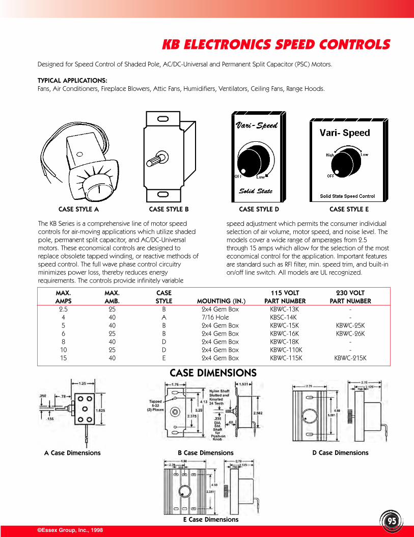
©Essex Group, Inc., 199895
KB ELECTRONICS SPEED CONTROLSDesigned for Speed Control of Shaded Pole, AC/DC-Universal and Permanent Split Capacitor (PSC) Motors.
TYPICAL APPLICATIONS:Fans, Air Conditioners, Fireplace Blowers, Attic Fans, Humidifiers, Ventilators, Ceiling Fans, Range Hoods.
CASE STYLE A
The KB Series is a comprehensive line of motor speedcontrols for air-moving applications which utilize shadedpole, permanent split capacitor, and AC/DC-Universalmotors. These economical controls are designed toreplace obsolete tapped winding, or reactive methods ofspeed control. The full wave phase control circuitryminimizes power loss, thereby reduces energyrequirements. The controls provide infinitely variable
MAX. MAX. CASE 115 VOLT 230 VOLTAMPS AMB. STYLE MOUNTING (IN.) PART NUMBER PART NUMBER
2.5 25 B 2x4 Gem Box KBWC-13K -4 40 A 7/16 Hole KBSC-14K -5 40 B 2x4 Gem Box KBWC-15K KBWC-25K6 25 B 2x4 Gem Box KBWC-16K KBWC-26K8 40 D 2x4 Gem Box KBWC-18K -10 25 D 2x4 Gem Box KBWC-110K -15 40 E 2x4 Gem Box KBWC-115K KBWC-215K
speed adjustment which permits the consumer individualselection of air volume, motor speed, and noise level. Themodels cover a wide range of amperages from 2.5through 15 amps which allow for the selection of the mosteconomical control for the application. Important featuresare standard such as RFl filter, min. speed trim, and built-inon/off line switch. All models are UL recognized.
CASE STYLE B CASE STYLE D CASE STYLE E
CASE DIMENSIONS
A Case Dimensions B Case Dimensions D Case Dimensions
E Case Dimensions
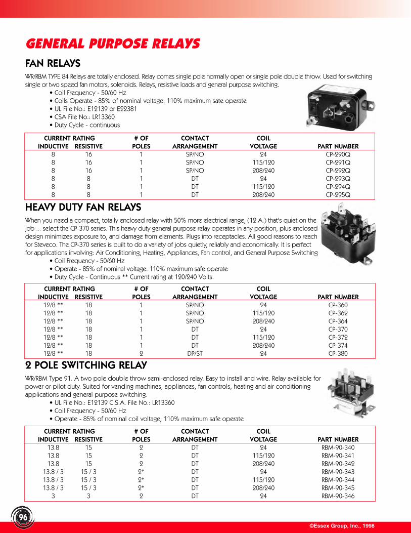
FAN RELAYSWR/RBM TYPE 84 Relays are totally enclosed. Relay comes single pole normally open or single pole double throw. Used for switchingsingle or two speed fan motors, solenoids. Relays, resistive loads and general purpose switching.
• Coil Frequency - 50/60 Hz• Coils Operate - 85% of nominal voltage: 110% maximum sate operate• UL File No.: E12139 or E22381• CSA File No.: LR13360• Duty Cycle - continuous
©Essex Group, Inc., 1998
GENERAL PURPOSE RELAYS
96
CURRENT RATING # OF CONTACT COILINDUCTIVE RESISTIVE POLES ARRANGEMENT VOLTAGE PART NUMBER
12/8 ** 18 1 SP/NO 24 CP-36012/8 ** 18 1 SP/NO 115/120 CP-36212/8 ** 18 1 SP/NO 208/240 CP-36412/8 ** 18 1 DT 24 CP-37012/8 ** 18 1 DT 115/120 CP-37212/8 ** 18 1 DT 208/240 CP-37412/8 ** 18 2 DP/ST 24 CP-380
2 POLE SWITCHING RELAYWR/RBM Type 91. A two pole double throw semi-enclosed relay. Easy to install and wire. Relay available forpower or pilot duty. Suited for vending machines, appliances, fan controls, heating and air conditioningapplications and general purpose switching.
• UL File No.: E12139 C.S.A. File No.: LR13360• Coil Frequency - 50/60 Hz• Operate - 85% of nominal coil voltage; 110% maximum safe operate
CURRENT RATING # OF CONTACT COILINDUCTIVE RESISTIVE POLES ARRANGEMENT VOLTAGE PART NUMBER
13.8 15 2 DT 24 RBM-90-34013.8 15 2 DT 115/120 RBM-90-34113.8 15 2 DT 208/240 RBM-90-342
13.8 / 3 15 / 3 2* DT 24 RBM-90-34313.8 / 3 15 / 3 2* DT 115/120 RBM-90-34413.8 / 3 15 / 3 2* DT 208/240 RBM-90-345
3 3 2 DT 24 RBM-90-346
CURRENT RATING # OF CONTACT COILINDUCTIVE RESISTIVE POLES ARRANGEMENT VOLTAGE PART NUMBER
8 16 1 SP/NO 24 CP-290Q8 16 1 SP/NO 115/120 CP-291Q8 16 1 SP/NO 208/240 CP-292Q8 8 1 DT 24 CP-293Q8 8 1 DT 115/120 CP-294Q8 8 1 DT 208/240 CP-295Q
HEAVY DUTY FAN RELAYSWhen you need a compact, totally enclosed relay with 50% more electrical range, (12 A.) that's quiet on thejob ... select the CP-370 series. This heavy duty general purpose relay operates in any position, plus encloseddesign minimizes exposure to, and damage from elements. Plugs into receptacles. All good reasons to reachfor Steveco. The CP-370 series is built to do a variety of jobs quietly, reliably and economically. It is perfectfor applications involving: Air Conditioning, Heating, Appliances, Fan control, and General Purpose Switching
• Coil Frequency - 50/60 Hz• Operate - 85% of nominal voltage: 110% maximum safe operate • Duty Cycle - Continuous ** Current rating at 120/240 Volts.
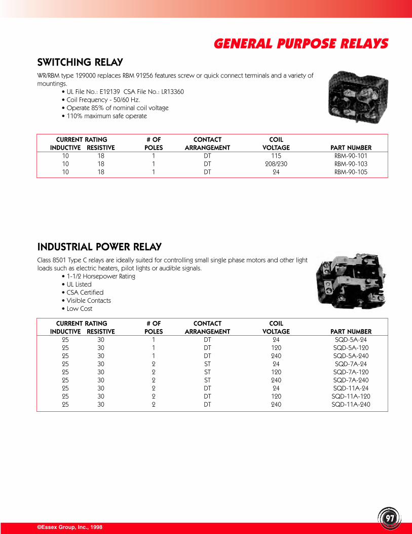
©Essex Group, Inc., 1998
GENERAL PURPOSE RELAYS
97
SWITCHING RELAYWR/RBM type 129000 replaces RBM 91256 features screw or quick connect terminals and a variety ofmountings.
• UL File No.: E12139 CSA File No.: LR13360• Coil Frequency - 50/60 Hz.• Operate 85% of nominal coil voltage• 110% maximum safe operate
CURRENT RATING # OF CONTACT COILINDUCTIVE RESISTIVE POLES ARRANGEMENT VOLTAGE PART NUMBER
10 18 1 DT 115 RBM-90-10110 18 1 DT 208/230 RBM-90-10310 18 1 DT 24 RBM-90-105
INDUSTRIAL POWER RELAYClass 8501 Type C relays are ideally suited for controlling small single phase motors and other lightloads such as electric heaters, pilot lights or audible signals.
• 1-1/2 Horsepower Rating• UL Listed• CSA Certified• Visible Contacts• Low Cost
CURRENT RATING # OF CONTACT COILINDUCTIVE RESISTIVE POLES ARRANGEMENT VOLTAGE PART NUMBER
25 30 1 DT 24 SQD-5A-2425 30 1 DT 120 SQD-5A-12025 30 1 DT 240 SQD-5A-24025 30 2 ST 24 SQD-7A-2425 30 2 ST 120 SQD-7A-12025 30 2 ST 240 SQD-7A-24025 30 2 DT 24 SQD-11A-2425 30 2 DT 120 SQD-11A-12025 30 2 DT 240 SQD-11A-240
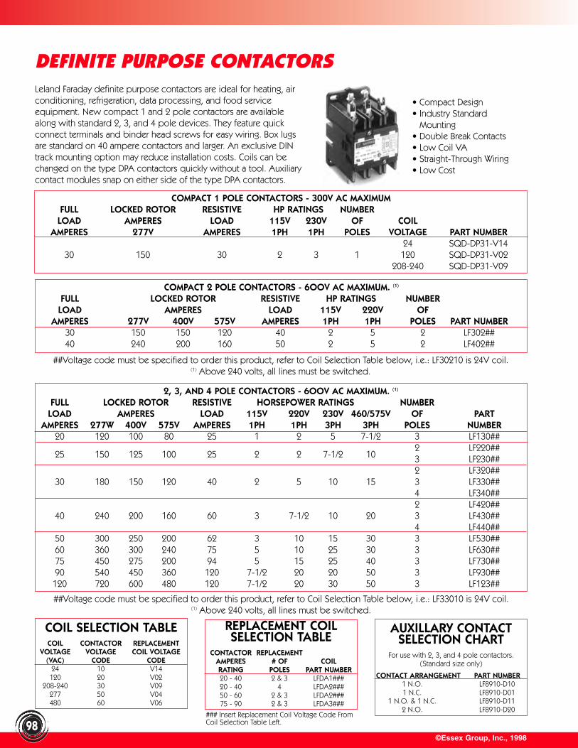
©Essex Group, Inc., 199898
DEFINITE PURPOSE CONTACTORS
• Compact Design• Industry Standard • Mounting• Double Break Contacts• Low Coil VA • Straight-Through Wiring• Low Cost
Leland Faraday definite purpose contactors are ideal for heating, airconditioning, refrigeration, data processing, and food serviceequipment. New compact 1 and 2 pole contactors are availablealong with standard 2, 3, and 4 pole devices. They feature quickconnect terminals and binder head screws for easy wiring. Box lugsare standard on 40 ampere contactors and larger. An exclusive DINtrack mounting option may reduce installation costs. Coils can bechanged on the type DPA contactors quickly without a tool. Auxiliarycontact modules snap on either side of the type DPA contactors.
COMPACT 1 POLE CONTACTORS - 300V AC MAXIMUMFULL LOCKED ROTOR RESISTIVE HP RATINGS NUMBER
LOAD AMPERES LOAD 115V 230V OF COILAMPERES 277V AMPERES 1PH 1PH POLES VOLTAGE PART NUMBER
24 SQD-DP31-V1430 150 30 2 3 1 120 SQD-DP31-V02
208-240 SQD-DP31-V09
COMPACT 2 POLE CONTACTORS - 6OOV AC MAXIMUM. (1)
FULL LOCKED ROTOR RESISTIVE HP RATINGS NUMBERLOAD AMPERES LOAD 115V 220V OF
AMPERES 277V 400V 575V AMPERES 1PH 1PH POLES PART NUMBER30 150 150 120 40 2 5 2 LF302##40 240 200 160 50 2 5 2 LF402##
##Voltage code must be specified to order this product, refer to Coil Selection Table below, i.e.: LF30210 is 24V coil.(1) Above 240 volts, all lines must be switched.
##Voltage code must be specified to order this product, refer to Coil Selection Table below, i.e.: LF33010 is 24V coil.(1) Above 240 volts, all lines must be switched.
COIL SELECTION TABLECOIL CONTACTOR REPLACEMENT
VOLTAGE VOLTAGE COIL VOLTAGE(VAC) CODE CODE
24 10 V14120 20 V02
208-240 30 V09277 50 V04480 60 V06
REPLACEMENT COIL SELECTION TABLE
CONTACTOR REPLACEMENTAMPERES # OF COILRATING POLES PART NUMBER20 - 40 2 & 3 LFDA1###20 - 40 4 LFDA2###50 - 60 2 & 3 LFDA2###75 - 90 2 & 3 LFDA3###
AUXILLARY CONTACT SELECTION CHART
For use with 2, 3, and 4 pole contactors.(Standard size only)
CONTACT ARRANGEMENT PART NUMBER1 N.O. LF8910-D101 N.C. LF8910-D01
1 N.O. & 1 N.C. LF8910-D112 N.O. LF8910-D20
### Insert Replacement Coil Voltage Code FromCoil Selection Table Left.
2, 3, AND 4 POLE CONTACTORS - 6OOV AC MAXIMUM. (1)
FULL LOCKED ROTOR RESISTIVE HORSEPOWER RATINGS NUMBERLOAD AMPERES LOAD 115V 220V 230V 460/575V OF PART
AMPERES 277W 400V 575V AMPERES 1PH 1PH 3PH 3PH POLES NUMBER20 120 100 80 25 1 2 5 7-1/2 3 LF130##
25 150 125 100 25 2 2 7-1/2 102 LF220##3 LF230##2 LF320##
30 180 150 120 40 2 5 10 15 3 LF330##4 LF340##2 LF420##
40 240 200 160 60 3 7-1/2 10 20 3 LF430##4 LF440##
50 300 250 200 62 3 10 15 30 3 LF530##60 360 300 240 75 5 10 25 30 3 LF630##75 450 275 200 94 5 15 25 40 3 LF730##90 540 450 360 120 7-1/2 20 20 50 3 LF930##120 720 600 480 120 7-1/2 20 30 50 3 LF123##
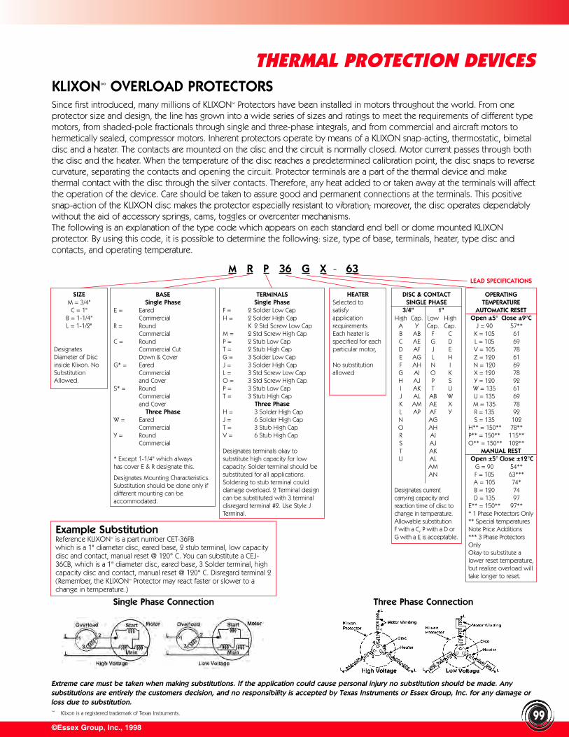
Extreme care must be taken when making substitutions. If the application could cause personal injury no substitution should be made. Anysubstitutions are entirely the customers decision, and no responsibility is accepted by Texas Instruments or Essex Group, Inc. for any damage orloss due to substitution.
©Essex Group, Inc., 1998
THERMAL PROTECTION DEVICES
99
SIZEM = 3/4"C = 1"
B = 1-1/4"L = 1-1/2"
DesignatesDiameter of Discinside Klixon. NoSubstitutionAllowed.
HEATERSelected to satisfy applicationrequirementsEach heater isspecified for eachparticular motor,
No substitutionallowed
DISC & CONTACTSINGLE PHASE
3/4" 1"High Cap. Low High
A Y Cap. Cap.B AB F CC AE G DD AF J EE AG L HF AH N IG AI O KH AJ P SI AK T UJ AL AB WK AM AE XL AP AF YN AGO AHR AIS AJT AKU AL
AMAN
Designates current carrying capacity andreaction time of disc tochange in temperature.Allowable substitutionF with a C, P with a D orG with a E is acceptable.
OPERATINGTEMPERATURE
AUTOMATIC RESETOpen ±5° Close ±9°C
J = 90 57**K = 105 61L = 105 69V = 105 78Z = 120 61N = 120 69X = 120 78Y = 120 92W = 135 61U = 135 69M = 135 78R = 135 92S = 135 102
H** = 150** 78**P** = 150** 115**O** = 150** 102**
MANUAL RESTOpen ±5° Close ±12°C
G = 90 54**F = 105 63***A = 105 74*B = 120 74D = 135 97
E** = 150** 97*** 1 Phase Protectors Only** Special temperatures Note Price Additions*** 3 Phase Protectors OnlyOkay to substitute alower reset temperature,but realize overload willtake longer to reset.
M R P 36 G X - 63LEAD SPECIFICATIONS
Example SubstitutionReference KLIXON∞ is a part number CET-36FBwhich is a 1" diameter disc, eared base, 2 stub terminal, low capacitydisc and contact, manual reset @ 120° C. You can substitute a CEJ-36CB, which is a 1" diameter disc, eared base, 3 Solder terminal, highcapacity disc and contact, manual reset @ 120° C. Disregard terminal 2(Remember, the KLIXON∞ Protector may react faster or slower to achange in temperature.)
Single Phase Connection
KLIXON∞ OVERLOAD PROTECTORSSince first introduced, many millions of KLIXON∞ Protectors have been installed in motors throughout the world. From oneprotector size and design, the line has grown into a wide series of sizes and ratings to meet the requirements of different typemotors, from shaded-pole fractionals through single and three-phase integrals, and from commercial and aircraft motors tohermetically sealed, compressor motors. Inherent protectors operate by means of a KLIXON snap-acting, thermostatic, bimetaldisc and a heater. The contacts are mounted on the disc and the circuit is normally closed. Motor current passes through boththe disc and the heater. When the temperature of the disc reaches a predetermined calibration point, the disc snaps to reversecurvature, separating the contacts and opening the circuit. Protector terminals are a part of the thermal device and makethermal contact with the disc through the silver contacts. Therefore, any heat added to or taken away at the terminals will affectthe operation of the device. Care should be taken to assure good and permanent connections at the terminals. This positivesnap-action of the KLIXON disc makes the protector especially resistant to vibration; moreover, the disc operates dependablywithout the aid of accessory springs, cams, toggles or overcenter mechanisms. The following is an explanation of the type code which appears on each standard end bell or dome mounted KLIXONprotector. By using this code, it is possible to determine the following: size, type of base, terminals, heater, type disc andcontacts, and operating temperature.
BASESingle Phase
E = Eared Commercial
R = RoundCommercial
C = Round Commercial Cut Down & Cover
G* = Eared Commercial and Cover
S* = Round Commercial and Cover
Three PhaseW = Eared
CommercialY = Round
Commercial
* Except 1-1/4" which alwayshas cover E & R designate this.
Designates Mounting Characteristics.Substitution should be done only ifdifferent mounting can beaccommodated.
TERMINALSSingle Phase
F = 2 Solder Low CapH = 2 Solder High Cap
K 2 Std Screw Low CapM = 2 Std Screw High CapP = 2 Stub Low CapT = 2 Stub High CapG = 3 Solder Low CapJ = 3 Solder High CapL = 3 Std Screw Low CapO = 3 Std Screw High CapP = 3 Stub Low CapT = 3 Stub High Cap
Three PhaseH = 3 Solder High CapJ = 6 Solder High CapT = 3 Stub High CapV = 6 Stub High Cap
Designates terminals okay tosubstitute high capacity for lowcapacity. Solder terminal should besubstituted for all applications.Soldering to stub terminal coulddamage overload. 2 Terminal designcan be substituted with 3 terminal disregard terminal #2. Use Style JTerminal.
Three Phase Connection
∞ Klixon is a registered trademark of Texas Instruments.
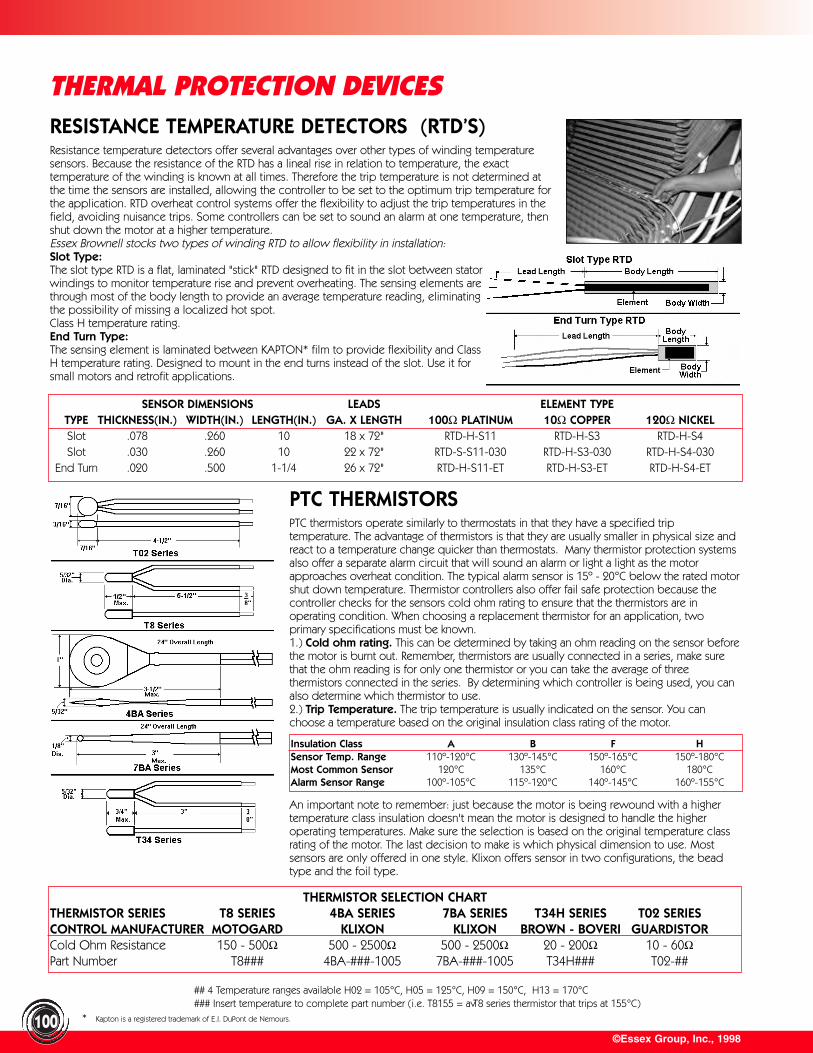
## 4 Temperature ranges available H02 = 105°C, H05 = 125°C, H09 = 150°C, H13 = 170°C### Insert temperature to complete part number (i.e. T8155 = a T8 series thermistor that trips at 155°C)
RESISTANCE TEMPERATURE DETECTORS (RTD’S)Resistance temperature detectors offer several advantages over other types of winding temperaturesensors. Because the resistance of the RTD has a lineal rise in relation to temperature, the exacttemperature of the winding is known at all times. Therefore the trip temperature is not determined atthe time the sensors are installed, allowing the controller to be set to the optimum trip temperature forthe application. RTD overheat control systems offer the flexibility to adjust the trip temperatures in thefield, avoiding nuisance trips. Some controllers can be set to sound an alarm at one temperature, thenshut down the motor at a higher temperature.Essex Brownell stocks two types of winding RTD to allow flexibility in installation:Slot Type:The slot type RTD is a flat, laminated "stick" RTD designed to fit in the slot between statorwindings to monitor temperature rise and prevent overheating. The sensing elements arethrough most of the body length to provide an average temperature reading, eliminatingthe possibility of missing a localized hot spot. Class H temperature rating.End Turn Type:The sensing element is laminated between KAPTON* film to provide flexibility and ClassH temperature rating. Designed to mount in the end turns instead of the slot. Use it forsmall motors and retrofit applications.
©Essex Group, Inc., 1998
THERMAL PROTECTION DEVICES
100
SENSOR DIMENSIONS LEADS ELEMENT TYPETYPE THICKNESS(IN.) WIDTH(IN.) LENGTH(IN.) GA. X LENGTH 100Ω PLATINUM 10Ω COPPER 120Ω NICKELSlot .078 .260 10 18 x 72" RTD-H-S11 RTD-H-S3 RTD-H-S4Slot .030 .260 10 22 x 72" RTD-S-S11-030 RTD-H-S3-030 RTD-H-S4-030
End Turn .020 .500 1-1/4 26 x 72" RTD-H-S11-ET RTD-H-S3-ET RTD-H-S4-ET
PTC THERMISTORSPTC thermistors operate similarly to thermostats in that they have a specified trip temperature. The advantage of thermistors is that they are usually smaller in physical size andreact to a temperature change quicker than thermostats. Many thermistor protection systemsalso offer a separate alarm circuit that will sound an alarm or light a light as the motorapproaches overheat condition. The typical alarm sensor is 15º - 20°C below the rated motorshut down temperature. Thermistor controllers also offer fail safe protection because thecontroller checks for the sensors cold ohm rating to ensure that the thermistors are inoperating condition. When choosing a replacement thermistor for an application, two primary specifications must be known. 1.) Cold ohm rating. This can be determined by taking an ohm reading on the sensor beforethe motor is burnt out. Remember, thermistors are usually connected in a series, make surethat the ohm reading is for only one thermistor or you can take the average of threethermistors connected in the series. By determining which controller is being used, you canalso determine which thermistor to use. 2.) Trip Temperature. The trip temperature is usually indicated on the sensor. You canchoose a temperature based on the original insulation class rating of the motor.
Insulation Class A B F HSensor Temp. Range 110º-120°C 130º-145°C 150º-165°C 150º-180°CMost Common Sensor 120°C 135°C 160°C 180°CAlarm Sensor Range 100º-105°C 115º-120°C 140º-145°C 160º-155°C
An important note to remember: just because the motor is being rewound with a higher temperature class insulation doesn't mean the motor is designed to handle the higher operating temperatures. Make sure the selection is based on the original temperature classrating of the motor. The last decision to make is which physical dimension to use. Most sensors are only offered in one style. Klixon offers sensor in two configurations, the beadtype and the foil type.
THERMISTOR SELECTION CHARTTHERMISTOR SERIES T8 SERIES 4BA SERIES 7BA SERIES T34H SERIES T02 SERIESCONTROL MANUFACTURER MOTOGARD KLIXON KLIXON BROWN - BOVERI GUARDISTORCold Ohm Resistance 150 - 500Ω 500 - 2500Ω 500 - 2500Ω 20 - 200Ω 10 - 60ΩPart Number T8### 4BA-###-1005 7BA-###-1005 T34H### T02-##
* Kapton is a registered trademark of E.I. DuPont de Nemours.
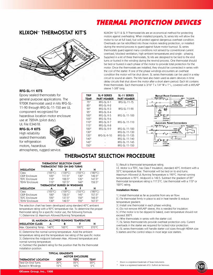
101
THERMAL PROTECTION DEVICESKLIXON∞ THERMOSTAT KIT’S
RFG-SL-11 KITSEpoxy sealed thermostats for general purpose applications. The9700K thermostat used in kits RFG-SL-11-90 through RFG-SL-11-150 are UL component recognized for hazardous location motor enclosureuse at 720VA (pilot duty). UL File E34618.RFG-SL-9 KITSHigh reliabilitysealed thermostatsfor refrigerationmotors, hazardousatmospheres, rugged service.
TRIP SL-9 SERIES SL-11 SERIESTEMP. PART NUMBER PART NUMBER75° RFG-SL-9-1 RFG-SL-11-7585° RFG-SL-9-2 -90° RFG-SL-9-3 RFG-SL-11-9095° RFG-SL-9-4 -100° RFG-SL-9-5 RFG-SL-11-100105° RFG-SL-9-6 -110° RFG-SL-9-7 RFG-SL-11-110115° RFG-SL-9-8 -120° RFG-SL-9-9 RFG-SL-11-120130° - RFG-SL-11-130135° RFG-SL-9-10 RFG-SL-11-135140° - RFG-SL-11-140145° - RFG-SL-11-145150° - RFG-SL-11-150
THERMOSTAT SELECTION CHARTTHERMOSTAT TIED ON END TURNS
INSULATION A B F HClass (105°C) (130°C) (155°C) (180°C)ODP Enclosure 105° 117.5° 130° 142.5°TEFC Enclosure 110° 122.5° 135° 147.5°TENV Enclosure 115° 127.5° 140° 152.5°
THERMOSTAT BURIED IN WINDINGSINSULATION A B F HClass (105°C) (130°C) (155°C) (180°C)ODP Enclosure 120° 132.5° 145° 157.5°TEFC Enclosure 125° 137.5° 150° 162.5°TENV Enclosure 130° 142.5° 155° 167.5°
The selection chart has been developed using standard 40°C ambienttemperature rating with a 90°C temperature rise. To determine the properthermostat rating for a specific motor use, the following formula. 1.) Determine UL Maximum Allowed Running Temperature.
UL MAXIMUM ALLOWED RUNNING TEMPERATUREINSULATION CLASS A B F HMax. Operating Temp. 140°C 165°C 190°C 215°C
2.) Determine the normal running temperature. Add the ambienttemperature rating and the temperature rise rating of the specific motor.3.) Determine the midpoint between Max. Allowed temperature and normal running temperature.4.) Subtract the gradient rating for the position that fits the thermostatinstallation position.
TYPICAL GRADIENTSMOTOR ENCLOSURE
THERMOSTAT LOCATION ODP TEFC TENVTied On End Turns 30°C 25°C 20°CBuried In Windings 15°C 10°C 5°C
5.) Result is thermostat temperature rating.I.E. Motor is a TEFC, has Class F Insulation, standard 40°C Ambient with a55°C temperature Rise. Thermostat will be tied on to end turns.Maximum Allowed UL Running Temperature is 190°C. Normal runningtemperature is 95°C. Midpoint is 142.5. Subtract the gradient of 25°thermostat temperature rating is 117.5°C. Use thermostat with a 115º or120°C rating.
Installation Notes:
1.) Install thermostat as far as possible from any air flow.2.) Tie thermostat firmly in place to aid in heat transfer & reducetemperature gradient.3.) Install one thermostat in each phase winding.4.) Do not remove MYLAR* sleeve, this is needed for insulation.5.) If the motor is to be dipped & baked, oven temperature should notexceed 300°F.6.) Wire thermostats in series with the starter coil.7.) SL Series thermostat kits provide overheat protection only. Currentoverloads in the starter are required for locked rotor protection.8.) SL series thermostats will handle starter coil sizes through NEMA size5 starters and the control relays in most large size starters.
KLIXON∞ SL11 & SL 9 Thermostat kits are an economical method for protectingmotors against overheating. When installed properly, SL series kits will allow themotor to run at full load, but will protect against dangerous overheat condition.Overloads can be retrofitted into those motors needing protection, or installedduring the rewind process to guard against future motor burnout. SL seriesthermostats guard against many conditions not sensed by conventional currentoverload, blocked ventilation, high ambient temperatures and single - phasing.Supplied in a kit of three thermostats, SL kits are designed to be tied to the endturns or buried in the winding during the rewind process. One thermostat shouldbe tied or buried in each phase of the motor to provide total protection for themotor. Once the thermostats are installed, they should be connected in series withthe coil of the starter. If one of the phase windings encounters an overheatcondition the motor will be shut down. SL series thermostats can be used in a relaycircuit to sound an alarm. The kits have also been used as alarm devices in timedelay circuits that shut down the motor after a short alarm period. Each kit containsthree thermostats. Each thermostat is 3/16" T x 1/4" W x 1" L, covered with a MYLAR*sleeve 1-3/8" long.
THERMOSTAT SELECTION PROCEDURE
©Essex Group, Inc., 1998
∞ Klixon is a registered trademark of Texas Instruments.
* Mylar is a registered trademark of E.I. DuPont de Nemours.
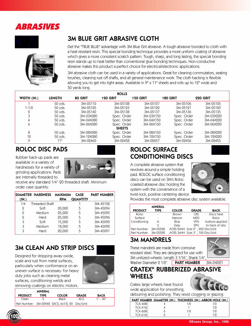
ROLOC DISC PADSRubber back-up pads areavailable in a variety ofhardnesses for a variety ofgrinding applications. Padsare internally threaded toreceive any standard 1/4”-20 threaded shaft. Minimumorder case quantity.
©Essex Group, Inc., 1998102
ABRASIVES
ROLOC SURFACE CONDITIONING DISCSA complete abrasive system thatrevolves around a simple holdingpad. ROLOC surface conditioningdiscs can be used on 3M’s Roloccoasted abrasive disc holding thesystem with the convenience of atwist-lock, positive centering device.Provides the most complete abrasive disc system available.
3M CLEAN AND STRIP DISCSDesigned for stripping away oxide,scale and rust from metal surfaces,particularly when conformance on anuneven surface is necessary. For heavyduty jobs such as cleaning metalsurfaces, conditioning welds andremoving coatings on electric motors.
CRATEX® RUBBERIZED ABRASIVEWHEELSCratex large wheels have foundwide application for smoothing,deburring and polishing. They resist clogging or glazing.
ROLLSWIDTH (IN.) LENGTH 80 GRIT 120 GRIT 150 GRIT 180 GRIT 220 GRIT
1 50 yds. 3M-05110 3M-05108 3M-05107 3M-05106 3M-051051-1/2 50 yds. 3M-05125 3M-05123 3M-05122 3M-05121 3M-05120
2 50 yds. 3M-05140 3M-05138 3M-05137 3M-05136 3M-051353 50 yds. 3M-03X080 Spec. Order 3M-03X150 Spec. Order 3M-03X2204 50 yds. 3M-04X080 Spec. Order 3M-04X150 Spec. Order 3M-04X2206 50 yds. 3M-06X080 Spec. Order 3M-06X150 Spec. Order 3M-06X220
SHEETS8 50 yds. 3M-08X080 Spec. Order 3M-08X150 Spec. Order 3M-08X22012 50 yds. 3M-12X080 Spec. Order 3M-12X150 Spec. Order 3M-12X2209 11" 3M-02460 3M-02458 3M-02457 3M-02456 3M-02455
3M BLUE GRIT ABRASIVE CLOTHGet the "TRUE BLUE" advantage with 3M Blue Grit abrasive. A tough abrasive bonded to cloth witha heat resistant resin. This special bonding technique provides a more uniform coating of abrasivewhich gives a more consistent scratch pattern. Tough, sharp, and long lasting, the special bondingresin stands up to heat better than conventional glue bonding techniques. Non-conductiveabrasive makes this product a perfect choice for electrical/electronic applications.
3M abrasive cloth can be used in a variety of applications. Great for cleaning commutators, seatingbrushes, cleaning rust off shafts, and all general maintenance work. The cloth backing is flexibleallowing you to get into tight areas. Available in 9" x 11" sheets and rolls up to 12" wide and 50 yards long.
DIAMETER HARDNESS MAXIMUM CASE PART NUMBER(IN.) RPM QUANTITY1/4 Threaded Shaft 1 3M-451022 Soft 20,000 5 3M-450942 Medium 25,000 5 3M-450952 Hard 25,000 5 3M-450963 Soft 15,000 5 3M-450903 Medium 18,000 5 3M-450923 Hard 20,000 5 3M-45091
MINERALPRODUCT TYPE COLOR GRADE BACK
Roloc - Brown CRS Discs haveSurface - Maroon MED Roloc
Conditioning A Blue VFN buttons appliedS Gray SFN to back of disc
Part Number: 3M-05528 ACRS 2xNH Size 2” , 200 Disc/UnitPart Number: 3M-05528 ACRS 3xNH Size 3” , 100 Disc/Unit
3M MANDRELSThese mandrels are made from corrosiveresistant steel. They are designed for use with3M unitized wheels. Length 3 1/16”, Shank 1/4”,Washer Diameter 2 1/2”.
MINERALPRODUCT TYPE COLOR GRADE BACK
Clean S Black XCS 1” - 30”
Part Number: 3M-00948 SXCS, 6x1/2, 20 Disc/UnitPART NUMBER DIAMETER (IN.) THICKNESS (IN.) ARBOR HOLE (IN.)
TCX-408C 4 1/2 1/2TCX-416C 4 1 1/2TCX-608C 6 1/2 1/2TCX-616C 6 1 1/2
PART NUMBER 3M-04021
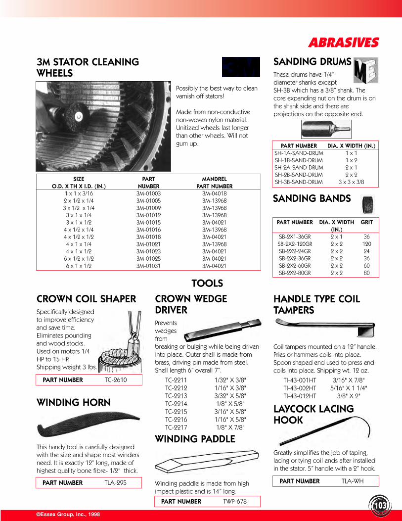
©Essex Group, Inc., 1998103
ABRASIVESSANDING DRUMSThese drums have 1/4”diameter shanks exceptSH-3B which has a 3/8” shank. Thecore expanding nut on the drum is onthe shank side and there areprojections on the opposite end.
3M STATOR CLEANING WHEELS
Possibly the best way to cleanvarnish off stators!
Made from non-conductivenon-woven nylon material.Unitized wheels last longerthan other wheels. Will notgum up.
TOOLS
CROWN COIL SHAPERSpecifically designedto improve efficiencyand save time.Eliminates poundingand wood stocks.Used on motors 1/4HP to 15 HP. Shipping weight 3 lbs.
CROWN WEDGEDRIVERPreventswedgesfrombreaking or bulging while being driveninto place. Outer shell is made frombrass, driving pin made from steel.Shell length 6” overall 7”.
TC-2211 1/32" X 3/8"TC-2212 1/16" X 3/8"TC-2213 3/32" X 5/8"TC-2214 1/8" X 5/8"TC-2215 3/16" X 5/8"TC-2216 1/16" X 5/8"TC-2217 1/8" X 7/8"
HANDLE TYPE COILTAMPERS
Coil tampers mounted on a 12” handle.Pries or hammers coils into place.Spoon shaped end used to press endcoils into place. Shipping wt. 12 oz.
TI-43-001HT 3/16" X 7/8"TI-43-002HT 5/16" X 1 1/4"TI-43-012HT 3/8" X 2"
WINDING HORN
This handy tool is carefully designedwith the size and shape most windersneed. It is exactly 12” long, made ofhighest quality bone fibre- 1/2” thick.
WINDING PADDLE
Winding paddle is made from highimpact plastic and is 14” long.
SIZE PART MANDRELO.D. X TH X I.D. (IN.) NUMBER PART NUMBER
1 x 1 x 3/16 3M-01003 3M-040182 x 1/2 x 1/4 3M-01005 3M-139683 x 1/2 x 1/4 3M-01009 3M-13968
3 x 1 x 1/4 3M-01012 3M-139683 x 1 x 1/2 3M-01015 3M-04021
4 x 1/2 x 1/4 3M-01016 3M-139684 x 1/2 x 1/2 3M-01018 3M-040214 x 1 x 1/4 3M-01021 3M-139684 x 1 x 1/2 3M-01023 3M-04021
6 x 1/2 x 1/2 3M-01025 3M-040216 x 1 x 1/2 3M-01031 3M-04021
PART NUMBER DIA. X WIDTH (IN.)SH-1A-SAND-DRUM 1 x 1SH-1B-SAND-DRUM 1 x 2SH-2A-SAND-DRUM 2 x 1SH-2B-SAND-DRUM 2 x 2SH-3B-SAND-DRUM 3 x 3 x 3/8
PART NUMBER DIA. X WIDTH GRIT(IN.)
SB-2X1-36GR 2 x 1 36SB-2X2-120GR 2 x 2 120SB-2X2-24GR 2 x 2 24SB-2X2-36GR 2 x 2 36SB-2X2-60GR 2 x 2 60SB-2X2-80GR 2 x 2 80
SANDING BANDS
LAYCOCK LACINGHOOK
Greatly simplifies the job of taping,lacing or tying coil ends after installedin the stator. 5” handle with a 2” hook.
PART NUMBER TWP-678
PART NUMBER TLA-WHPART NUMBER TLA-295
PART NUMBER TC-2610

©Essex Group, Inc., 1998
TOOLSLAYCOCK LAMINATIONTOOTH STRAIGHTENERSDesigned with a square end to permit the use of a socket or box end wrench to apply torque. Theteardrop shaped blade adds strengthand minimizes flexing when using fulllength tool. Available in three sizes tofit stator slots up to 150 HP. Part Number: TLA-LTS Complete set of threesizes listed below. Part Number: TLA-LTS-1 1/2” blade height,Wrench fitting 3/8” Square. Part Number: TLA-LTS-2 5/8” blade height,Wrench fitting 1/2” Square. Part Number: TLA-LTS-3 3/4” blade height,Wrench fitting 1/2” Square.
COIL TAMPING PLIERS
The perfect tool for tamping coils intoslots. Does not damage insulation. Fitsthe smallest stators. Part Number: NTP-100 Complete set pliers and
four jaws.Part Number: NTP-101 Pliers OnlyPart Number: NTP-102 5/32” JawsPart Number: NTP-103 3/16” JawsPart Number: NTP-104 1/4” Jaws
CLAUSS SHEARS
General purpose shop shears forcutting wire, insulation, banding andhundreds of other uses.
CABLE CUTTERThis cable cutter is designed to cut insulated copper or aluminum multi-strand cable or wire quickly and cleanly. Features:• Cuts copper or aluminum multi-strand cable
or wire • Precise one hand shearing action• Patented “off-set bite” eliminates compression/
frayed ends• Heat treated high carbon steel shear edges• Drop forge, heat treated frame• Heavy vinyl handle safety covers
COIL TAMPING TOOL
IDEAL CONTINUITYTESTER
Pen-lite battery powered, tests deadcircuits without live wire connections.Handy tester for checking continuity ofdead circuits, grounds on conduitsystems identifying wires in multi-wirecable. Unit is powered by two pen-lite batteries not supplied and giveslight signal to indicate a completecircuit. Has a four foot removable cordequipped with alligator clips.
WIRE GAUGEAmerican standardfor non ferrousmetals. Gauges wire,sheets and plates ofbrass, copper andaluminum. Decimalequivalents stamped on backside. Range 0 to 36 gauge.
PRECISION VERNIERCALIPER 6”For I.D., O.D., and depth measurements. Made from harden polished steel. Reads 1/1000 of an inch on lowerscale and 1/20 mm on uppercscale.Quicklock provides instant adjustmentand accurate reading.
WEDGE REMOVERRemoves old wedges from armatures and stators. The coarse teeth ranging from 3/32” to 1/8”thickness from front to back, bite firmlyinto the wedge. The curved bladeallows application of driving force atbest possible angle.
EPOXY SPRAY GUNThis specially designed gun permits easyspraying of unthinned Epoxylite 213 andDolph CC-1081 when 80 to 100 PSI air pressure is available. Easy control is obtained with positive air valve permitting a puff or full blast at the operators choice. The gun is also usefulfor “solvent blasting” in cleaning operations.
IDEAL HAND GRIPWIRE STRIPPERCuts and strips insulation, scrapeswire, straightens kinks and sharp bends. Hardened tool steel blade, removable for resharpening or replacement.
SLOT CLEANINGBRUSH
This inexpensive slot cleaning brushcan be one of the most useful tools inyour shop. The brush diameter is 1/2”,brush length 4”, total length 15”.
104
PART NUMBER DESCRIPTIONTSCR-4248 SHEARS;7.75";STRAIGHT TSCR-4268 SHEARS;8.25";STRAIGHT
TSCR-4268-KBL SHEARS;8.25"; KNIFEBLADES LEFT
TSCR-4877 SHEARS;LIGHT METAL;7"
PART NUMBER TUP-B41
PART NUMBER TDSG-100
PART NUMBER TWS-45-021PART NUMBER TVC-100
PART NUMBER TWSG-100
PART NUMBER TWB-1600
PART NUMBER TWR-100
PART NUMBER TI-61-030
PART NUMBER DESCRIPTIONTC-2201 3/16” X 7/8” TC-2202 5/16’ X 1-1/4”TC-2203 3/8’ X 2’
TC-2204-NO-HANDLE 3/8” X 4”
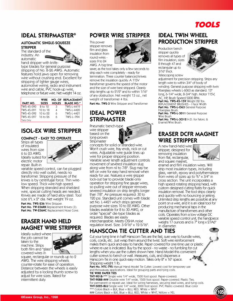
©Essex Group, Inc., 1998
TOOLS
ISOL-EX WIRE STRIPPERCOMPACT - EASY TO OPERATEStrips all typesof insulatedwires from size6 to 23 AWG.Ideally suited forelectric motorrepair. Built-invariable speed control, can be pluggeddirectly into wall outlet, needs notransformer. Stripping pressure of theknives is by centrifugal force. Thin wire-low speed. Thick wire-high speed.When stripping stranded and shieldedwire, special cutting heads are needed.Knives are made of hard alloy steel. Toolsize 6"L x 2" dia. Net weight 19 oz.Part No. TWS-236 Wire Stripper.Part No. TW-236RK Replacement Knives (3).Part No. TW-236NC Replacement Nose Cone.
IDEAL TWIN WHEELPRODUCTION STRIPPERProduction benchstripper quicklyremoves all types offilm insulation, sizes8 through 47 andrectangular up to3/16" thick.Telescoping screwadjustment for precision stripping. Strips anylength wire to within 3/4" of body ofwinding. General purpose stripping with twinfiberglass wheels L-6063 as standard. 13"long, 6-1/4" wide, 8-3/4" high. Motor 115V,AC, HP, Brush Speed 5000 RPM.Part No. TWS-45-159 Weight 22⁄ lbs.REPLACEMENT BRUSHES - I Face WidthPart No. TWS-L-O63 General Purpose Fiberglass Brush.Part No. TWS-L-3011 General Purpose Wire Brush.Part No. TWS-L-3O12 H.D. for Fabric &Enamel/Wire Brush.
IDEAL POWERSTRIPMASTERPneumatic bench-type wire stripper based on the long-proven Stripmaster concepts for solid or stranded wire.Won't crush wire, fray ends, nick or cutwires. Adjustable wire guide lines upwire for proper stripping position.Variable sever length adjustment controlsmovement of severed insulation slugalong wire from nil to 7/8". Slug may beleft on wire for easy hand removal whenready for use. Features a wire gripperlock-out bar to provide blade-onlyoperation for stripping fine gauge wires,so pulling wire out of stripper removessevered insulation on strip lengths longerthan 7/8". Air pressure required: 30 to120 psi. Standard unit comes with bladeset No. L-4421 which strips generalpurpose wire sizes 10 to 22 AWG. Otherblades available for 8 to 30 AWG, ororder "special" die-type blades asrequired. Blades are easilyinterchangeable. Meets OSHA noiseregulation level. Size: 3-9/16" x 12-5/16".
ERASER DCFR MAGNETWIRE STRIPPERA new hand-held wirestripper, designed forremoving insulationfrom flat, rectangular,and square magnet,enamel and film insulation wires. Willstrip most insulation types, includingglass, varnish, epoxy and polythermalezefrom wires of sizes up to %" x 3/4" incross section. The unit incorporates ahigh speed rotating stripping head, withcustom designed cutting flutes for quickinsulation removal. The tool strips cleanlyand quickly with no bouncing or jerking.Unlimited strip lengths are possible at anypoint on a wire, and it is an ideal tool forproducing mechanical taps in themanufacture of transformers and othercoils. Operates from a low voltage DCvariable speed control unit, the handpieceweighs 17 ounces and is 7" long x 27A6"in diameter.
ERASER HAND HELDMAGNET WIRE STRIPPERIdeally suited wherethe job cannot betaken to themachine. Stripsboth film and "glass"covered wires insquare, rectangular or rounds up to 2AWG. The wire stripping wheelscounter-rotate for ease of operation.Distance between the wheels is easilyadjusted by a locking thumb screw toadjust for wire sizes. Rated forintermittent duty.
IDEAL STRIPMASTER®
AUTOMATIC SINGLE-SOUEEZE STRIPPERThe standard of the industry. An automatic hand stripper with knife-type blades for general purposestripping of No. 8-26 AWG. Automaticfeatures hold jaws open for removingwire without crushing end. Excellent forstripping of lighter gauge wires,automotive wiring, radio and instrumentwire and cable, PVC hook-up wire,telephone or fixture wire. Net weight 14 oz.
POWER WIRE STRIPPERThis powerstripper removesfilm and glassinsulation fromround wires -sizes 9 to 24AWG. A big timesaver, as the tool takes only a few seconds tostrip each wire completely - ready fortermination. Three counter balanced knivesremove the insulation quickly. A 115Vtransformer governs the speed of the motorand the size of wire best stripped. Cleanlystrip lengths up to 21/2" and to within 1/16"of any obstruction. Net weight 13 oz., netweight of transformer 4 lbs.Part No. TWS-3 Wire Stripper and Transformer
WIRE NO. OF REPLACEMENTPART NO. SIZES HOLES BLADE NO.*
TWS-45-090 B to 12 3 TWS-L-4419TWS-45-091 10 to 18 4 TWS-L-4420TWS-45-092 10 to 22 6 TWS-L-4421TWS-45-097 16 to 26 6 TWS-L~994*Sets Only
HANSCOM TIE CUTTER AND TIESCut your tying time in half! Hanscom Ties are the fast, sure way to bundle wires, coils, cords, etc. Just wrap them around the twist. Soft wire reinforcement makes them quick and easy to handle. Paper covered for one-time use or plastic where re-use is indicated. Buy by the spool - no waste - no fumbling for cut lengths when you use the cutters shown here. Hand Model-this convenient cutter screws to bench or wall. Measures, cuts, and dispenses a Hanscom-Tie in one quick easy motion. Takes only 8" x 16" space. Shipping weight 1 lb. Part No. HTC-795 Manual Hand Model Tie Cutter. Lowest cost for temporary use and throwaway applications. Ideal for grouping parts and tying coils.TIE WIRE PAPER TIESTHT-9018-*** Single wire 1/4" wide, 1500 foot spool. Paper-covered.THT-9088-### Double wire 1/4" wide, 1500 foot spool. Paper-covered. Plastic Ties.For permanent or repeat use. Ideal for wiring harnesses, securing lead wires, and tying coils.THT-5025-BLU Single wire 1/4" wide, 3000 foot spool. PVC Plastic-covered. Blue color*** Colors Black = BLK, Blue = BLU, RED, White = WHT### Colors Black = BLK, Blue = BLU, RED, White = WHT, Yellow = YEL 105
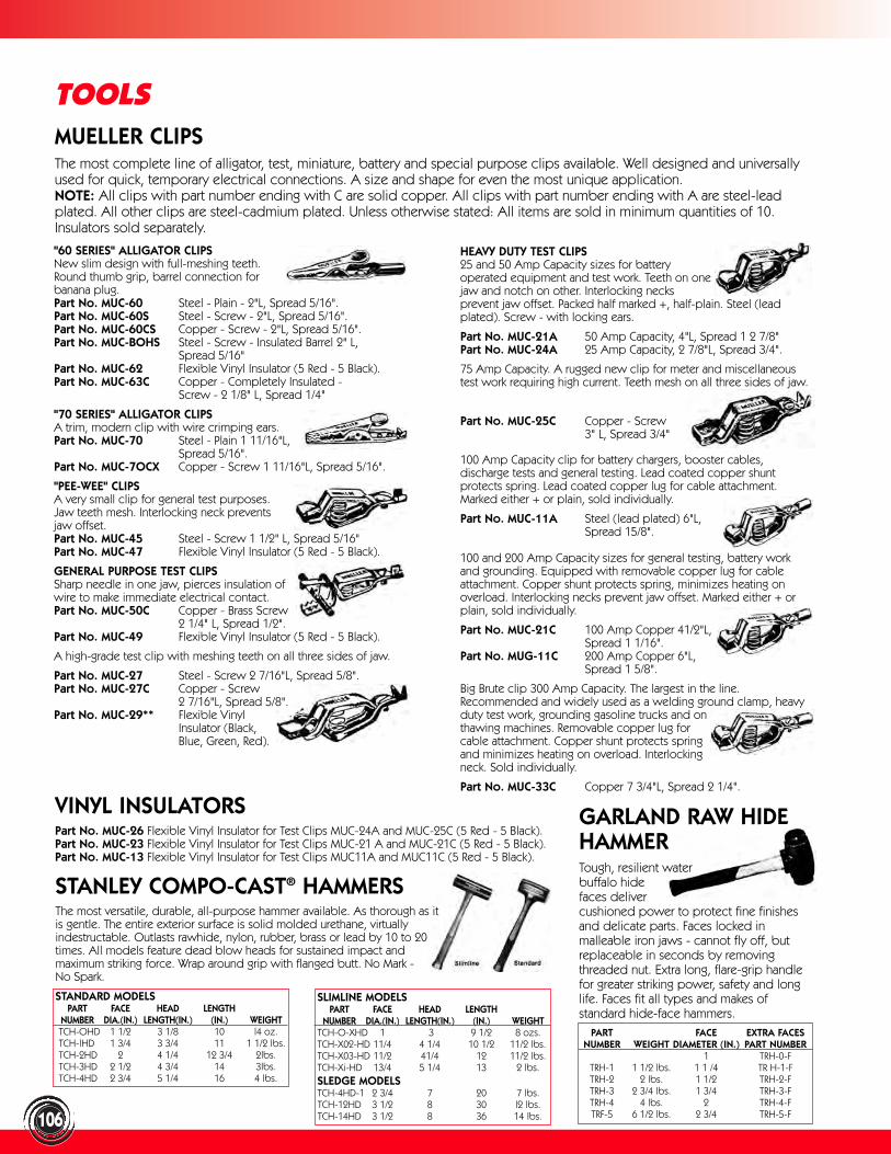
STANDARD MODELSPART FACE HEAD LENGTH
NUMBER DIA.(IN.) LENGTH(IN.) (IN.) WEIGHTTCH-OHD 1 1/2 3 1/8 10 l4 oz.TCH-lHD 1 3/4 3 3/4 11 1 1/2 lbs.TCH-2HD 2 4 1/4 12 3/4 2lbs.TCH-3HD 2 1/2 4 3/4 14 3lbs.TCH-4HD 2 3/4 5 1/4 16 4 lbs.
106
TOOLSMUELLER CLIPSThe most complete line of alligator, test, miniature, battery and special purpose clips available. Well designed and universallyused for quick, temporary electrical connections. A size and shape for even the most unique application. NOTE: All clips with part number ending with C are solid copper. All clips with part number ending with A are steel-leadplated. All other clips are steel-cadmium plated. Unless otherwise stated: All items are sold in minimum quantities of 10.Insulators sold separately.
"60 SERIES" ALLIGATOR CLIPSNew slim design with full-meshing teeth. Round thumb grip, barrel connection for banana plug.Part No. MUC-60 Steel - Plain - 2"L, Spread 5/16".Part No. MUC-60S Steel - Screw - 2"L, Spread 5/16".Part No. MUC-60CS Copper - Screw - 2"L, Spread 5/16".Part No. MUC-BOHS Steel - Screw - Insulated Barrel 2" L,
Spread 5/16"Part No. MUC-62 Flexible Vinyl Insulator (5 Red - 5 Black).Part No. MUC-63C Copper - Completely Insulated -
Screw - 2 1/8" L, Spread 1/4"
"70 SERIES" ALLIGATOR CLIPSA trim, modern clip with wire crimping ears.Part No. MUC-70 Steel - Plain 1 11/16"L,
Spread 5/16".Part No. MUC-7OCX Copper - Screw 1 11/16"L, Spread 5/16".
"PEE-WEE" CLIPSA very small clip for general test purposes. Jaw teeth mesh. Interlocking neck prevents jaw offset.Part No. MUC-45 Steel - Screw 1 1/2" L, Spread 5/16"Part No. MUC-47 Flexible Vinyl Insulator (5 Red - 5 Black).
GENERAL PURPOSE TEST CLIPSSharp needle in one jaw, pierces insulation of wire to make immediate electrical contact.Part No. MUC-50C Copper - Brass Screw
2 1/4" L, Spread 1/2".Part No. MUC-49 Flexible Vinyl Insulator (5 Red - 5 Black).
A high-grade test clip with meshing teeth on all three sides of jaw.
Part No. MUC-27 Steel - Screw 2 7/16"L, Spread 5/8".Part No. MUC-27C Copper - Screw
2 7/16"L, Spread 5/8".Part No. MUC-29** Flexible Vinyl
Insulator (Black, Blue, Green, Red).
HEAVY DUTY TEST CLIPS25 and 50 Amp Capacity sizes for battery operated equipment and test work. Teeth on one jaw and notch on other. Interlocking necks prevent jaw offset. Packed half marked +, half-plain. Steel (leadplated). Screw - with locking ears.
Part No. MUC-21A 50 Amp Capacity, 4"L, Spread 1 2 7/8" Part No. MUC-24A 25 Amp Capacity, 2 7/8"L, Spread 3/4".
75 Amp Capacity. A rugged new clip for meter and miscellaneoustest work requiring high current. Teeth mesh on all three sides of jaw.
Part No. MUC-25C Copper - Screw 3" L, Spread 3/4"
100 Amp Capacity clip for battery chargers, booster cables,discharge tests and general testing. Lead coated copper shuntprotects spring. Lead coated copper lug for cable attachment.Marked either + or plain, sold individually.
Part No. MUC-11A Steel (lead plated) 6"L, Spread 15/8".
100 and 200 Amp Capacity sizes for general testing, battery workand grounding. Equipped with removable copper lug for cableattachment. Copper shunt protects spring, minimizes heating onoverload. Interlocking necks prevent jaw offset. Marked either + orplain, sold individually.
Part No. MUC-21C 100 Amp Copper 41/2"L, Spread 1 1/16".
Part No. MUG-11C 200 Amp Copper 6"L, Spread 1 5/8".
Big Brute clip 300 Amp Capacity. The largest in the line.Recommended and widely used as a welding ground clamp, heavyduty test work, grounding gasoline trucks and on thawing machines. Removable copper lug for cable attachment. Copper shunt protects spring and minimizes heating on overload. Interlocking neck. Sold individually.
Part No. MUC-33C Copper 7 3/4"L, Spread 2 1/4".
VINYL INSULATORSPart No. MUC-26 Flexible Vinyl Insulator for Test Clips MUC-24A and MUC-25C (5 Red - 5 Black).Part No. MUC-23 Flexible Vinyl Insulator for Test Clips MUC-21 A and MUC-21C (5 Red - 5 Black).Part No. MUC-13 Flexible Vinyl Insulator for Test Clips MUC11A and MUC11C (5 Red - 5 Black).
STANLEY COMPO-CAST® HAMMERSThe most versatile, durable, all-purpose hammer available. As thorough as it is gentle. The entire exterior surface is solid molded urethane, virtually indestructable. Outlasts rawhide, nylon, rubber, brass or lead by 10 to 20 times. All models feature dead blow heads for sustained impact and maximum striking force. Wrap around grip with flanged butt. No Mark - No Spark.
GARLAND RAW HIDEHAMMERTough, resilient water buffalo hide faces deliver cushioned power to protect fine finishesand delicate parts. Faces locked inmalleable iron jaws - cannot fly off, butreplaceable in seconds by removingthreaded nut. Extra long, flare-grip handlefor greater striking power, safety and longlife. Faces fit all types and makes ofstandard hide-face hammers.
PART FACE EXTRA FACESNUMBER WEIGHT DIAMETER (IN.) PART NUMBER
1 TRH-0-FTRH-1 1 1/2 lbs. 1 1 /4 TR H-1-FTRH-2 2 lbs. 1 1/2 TRH-2-FTRH-3 2 3/4 lbs. 1 3/4 TRH-3-FTRH-4 4 lbs. 2 TRH-4-FTRF-5 6 1/2 lbs. 2 3/4 TRH-5-F
SLIMLINE MODELSPART FACE HEAD LENGTH
NUMBER DIA.(IN.) LENGTH(IN.) (IN.) WEIGHTTCH-O-XHD 1 3 9 1/2 8 ozs.TCH-X02-HD 11/4 4 1/4 10 1/2 11/2 lbs.TCH-X03-HD 11/2 41/4 12 11/2 lbs.TCH-Xi-HD 13/4 5 1/4 13 2 lbs.SLEDGE MODELSTCH-4HD-1 2 3/4 7 20 7 lbs.TCH-12HD 3 1/2 8 30 l2 lbs.TCH-14HD 3 1/2 8 36 14 lbs.

AIR HAMMER CHISELS
Part No. TC-2632 1/2" blade widthAir Hammer ShankPart No. TC-2633 5/8" blade widthAir Hammer ShankPart No. TC-2634 3/4" blade widthAir Hammer ShankThe crescent eliminates ragged edgesand prevents gouging of stators Part No. TC-2630 Set of 3 Air HammerShanks listed above. Available in sets ofthree different sizes (i.e. 1/2 ", 5/8",3/4'") Individually or with Parker-Taper Shank .
©Essex Group, Inc., 1998107
TOOLSMARTINDALE AIRGRINDERUse with carbide rotary burrs. The kit includes a high speed precision manufactured air grinder and five 2 1/4” long solid carbide 1/4” diameter rotary burrs (burrs include RB4, RC4,RD4, RH4 and RJ4). Lightweight (1 lb.6 oz.) and high speed (21,000 RPM).Recommended air pressure 70-90 PSI,air inlet is 1/4” female N.P.T.F. Burrs - 6inchs long Tungsten carbide burrs.
Part Number: TAG-38A kit with 5burrsPart Number: TAG-M12 Grinder onlyPart Number: TAG-128221-700Filter/LubricatorPart NumberTAG-RB4-6
TAG-RC4-6
TAG-RD4-6
TAG-RH4-6
TAG-RJ4-6
BLUE DART AIR GUNA deluxe air gun that delivers maximum power to move debris, chips and dust quickly and efficiently. It also meets OSHA regulations with new vented nozzle. Nozzle tipsdelivers 150 PSI.
AIR GRINDERHeavy duty straight air grinder for thebest economy is equipped with aJacobs three jaw chuck. Chuck key isincluded. 16,000 to 16,000 RPM noload speed. 1/4” collect size.
POW'R BLO AIR HAMMERSSPECIFICALLY DESIGNED FOR MOTOR STRIPPINGOne piece barrel - machined from finest tool steel -properly hardened and tempered. Two piece -patented main valve - made of shock steel precisionground, hardened and tempered. 3500 strokes perminutes. Air requirement - 4 cubic feet per minuteat 80 to 150 psi.
Part No. TPH-171 Safety Tool Holder - It'spractically impossible for a tool to fly out of the hammer. Chisels cannot stick inthe works due to the tool holder. Replacement parts or fast factory repair available.Separate oiling access for easy care and maintenance.
Part No. TPH-25 Pow'r Blo Heavy Duty Hammer complete with pressure regulatorand safety tool holder. Shipping weight 8 lbs. Part No. TPH-75 Pow'r Blo HeavyDuty Hammer complete with pressure regulator, a complete set of strippingchisels, and safety tool holders.
ACCESSORIESPart No. TPH-171 Safety Tool Holder for Pow'r Blo Hammer.Part No. TPH-305U Tool Holding Spring for Pow'r Blo Hammer.Part No. TPH-1VE 1/4" wide Parker Taper Shank Chisel.Part No. TPH-20F 3/4" wide offset Flat Edge Chisel.Part No. TPH-3CE Curved Edge Parker Taper Shank Chisel.Part No. TPH-4CE 2A" wide Curved Edge Chisel.Part No. TPH-55T 11/4" Saw Tooth Edge Chisel.Part No. TPH-2350 Complete set of 5 Pow'r Blo Chisels.
CROWN HEAVY DUTYAIR HAMMER
For high speed coil stripping. Featuresa universal spring retainer. Operatorcan easily rotate the cutting tool whileoperating hammer. The hammer mayalso be used for cutting panels, rivets,bolts, removing drum lids, and setting1/4" soft iron and aluminum rivets.Delivers 3,500 blows per minute; usesonly 4 cubic feet of air per minute at80 to 150 psi.Part No. TC-2707 Air HammerShipping weight 4 lbs.Part No. TC-2742 Combination AirHammer and set of 3 chisels. Shippingweight 6 lbs.
COIL STRIPPINGCHISELSPart No. TC-2622 1/4" blade widthStripping ChiselPart No. TC-2623 5/8" blade widthStripping ChiselPart No. TC-2624 3/4" blade widthStripping ChiselPart No. TC-2620 Set of 3 StrippingChisels listed above
PART NUMBER TPH-001
PART NUMBER TPH-211
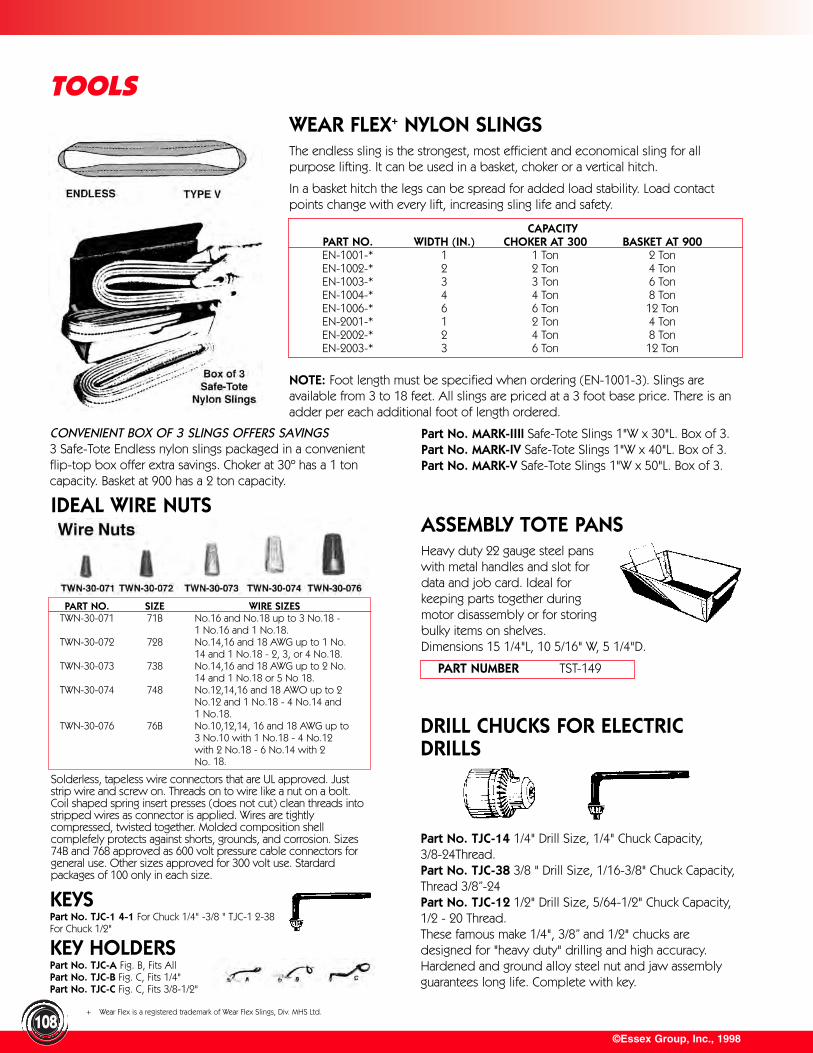
©Essex Group, Inc., 1998
TOOLS
108
WEAR FLEX+ NYLON SLINGSThe endless sling is the strongest, most efficient and economical sling for allpurpose lifting. It can be used in a basket, choker or a vertical hitch.
In a basket hitch the legs can be spread for added load stability. Load contactpoints change with every lift, increasing sling life and safety.
NOTE: Foot length must be specified when ordering (EN-1001-3). Slings areavailable from 3 to 18 feet. All slings are priced at a 3 foot base price. There is anadder per each additional foot of length ordered.
IDEAL WIRE NUTS
Solderless, tapeless wire connectors that are UL approved. Juststrip wire and screw on. Threads on to wire like a nut on a bolt.Coil shaped spring insert presses (does not cut) clean threads intostripped wires as connector is applied. Wires are tightlycompressed, twisted together. Molded composition shellcomplefely protects against shorts, grounds, and corrosion. Sizes74B and 768 approved as 600 volt pressure cable connectors forgeneral use. Other sizes approved for 300 volt use. Stardardpackages of 100 only in each size.
ASSEMBLY TOTE PANSHeavy duty 22 gauge steel panswith metal handles and slot for data and job card. Ideal forkeeping parts together duringmotor disassembly or for storingbulky items on shelves. Dimensions 15 1/4"L, 10 5/16" W, 5 1/4"D.
DRILL CHUCKS FOR ELECTRICDRILLS
Part No. TJC-14 1/4" Drill Size, 1/4" Chuck Capacity, 3/8-24Thread.Part No. TJC-38 3/8 " Drill Size, 1/16-3/8" Chuck Capacity,Thread 3/8”-24Part No. TJC-12 1/2" Drill Size, 5/64-1/2" Chuck Capacity, 1/2 - 20 Thread.These famous make 1/4", 3/8” and 1/2" chucks aredesigned for "heavy duty" drilling and high accuracy.Hardened and ground alloy steel nut and jaw assemblyguarantees long life. Complete with key.
KEYSPart No. TJC-1 4-1 For Chuck 1/4" -3/8 " TJC-1 2-38For Chuck 1/2"
KEY HOLDERSPart No. TJC-A Fig. B, Fits AllPart No. TJC-B Fig. C, Fits 1/4"Part No. TJC-C Fig. C, Fits 3/8-1/2"
CAPACITYPART NO. WIDTH (IN.) CHOKER AT 300 BASKET AT 900EN-1001-* 1 1 Ton 2 TonEN-1002-* 2 2 Ton 4 TonEN-1003-* 3 3 Ton 6 TonEN-1004-* 4 4 Ton 8 TonEN-1006-* 6 6 Ton 12 TonEN-2001-* 1 2 Ton 4 TonEN-2002-* 2 4 Ton 8 TonEN-2003-* 3 6 Ton 12 Ton
CONVENIENT BOX OF 3 SLINGS OFFERS SAVINGS3 Safe-Tote Endless nylon slings packaged in a convenientflip-top box offer extra savings. Choker at 30º has a 1 toncapacity. Basket at 900 has a 2 ton capacity.
PART NO. SIZE WIRE SIZESTWN-30-071 71B No.16 and No.18 up to 3 No.18 -
1 No.16 and 1 No.18.TWN-30-072 728 No.14,16 and 18 AWG up to 1 No.
14 and 1 No.18 - 2, 3, or 4 No.18.TWN-30-073 738 No.14,16 and 18 AWG up to 2 No.
14 and 1 No.18 or 5 No 18.TWN-30-074 748 No.12,14,16 and 18 AWO up to 2
No.12 and 1 No.18 - 4 No.14 and1 No.18.
TWN-30-076 76B No.10,12,14, 16 and 18 AWG up to3 No.10 with 1 No.18 - 4 No.12with 2 No.18 - 6 No.14 with 2 No. 18.
Part No. MARK-IIIl Safe-Tote Slings 1"W x 30"L. Box of 3.Part No. MARK-IV Safe-Tote Slings 1"W x 40"L. Box of 3.Part No. MARK-V Safe-Tote Slings 1"W x 50"L. Box of 3.
PART NUMBER TST-149
+ Wear Flex is a registered trademark of Wear Flex Slings, Div. MHS Ltd.
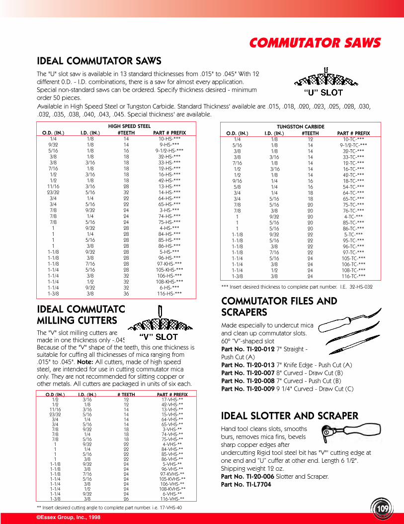
** Insert desired cutting angle to complete part number. i.e. 17-VHS-40
IDEAL SLOTTER AND SCRAPERHand tool cleans slots, smoothsburs, removes mica fins, bevelssharp copper edges afterundercutting Rigid tool steel bit has "V"' cutting edge atone end and “U” cuffer at other end. Length 6 1/2".Shipping weight 12 oz.Part No. TI-20-006 Slotter and Scraper.Part No. TI-L7704
©Essex Group, Inc., 1998
COMMUTATOR SAWS
109
COMMUTATOR FILES ANDSCRAPERSMade especially to undercut mica and clean up commutator slots. 60º ”V”-shaped slotPart No. TI-20-012 7" Straight - Push Cut (A)Part No. TI-20-013 7" Knife Edge - Push Cut (A)Part No. TI-20-007 8" Curved - Draw Cut (B)Part No. TI-20-008 7" Curved - Push Cut (B)Part No. TI-20-009 9 1/4" Curved - Draw Cut (C)
IDEAL COMMUTATOR SAWSThe "U" slot saw is available in 13 standard thicknesses from .015" to .045" With 12different 0.D. - I.D. combinations, there is a saw for almost every application.Special non-standard saws can be ordered. Specify thickness desired - minimumorder 50 pieces.
IDEAL COMMUTATORMILLING CUTTERSThe "V" slot milling cutters are made in one thickness only -.045". Because of the "V" shape of the teeth, this one thickness issuitable for cuffing all thicknesses of mica ranging from.015" to .045". Note: All cutters, made of high speedsteel, are intended for use in cutting commutator micaonly. They are not recommended for slitting copper orother metals. All cutters are packaged in units of six each.
Available in High Speed Steel or Tungston Carbide. Standard Thickness' available are .015, .018, .020, .023, .025, .028, .030,.032, .035, .038, .040, .043, .045. Special thickness' are available.
HIGH SPEED STEELO.D. (IN.) I.D. (IN.) #TEETH PART # PREFIX
1/4 1/8 14 10-HS-***9/32 1/8 14 9-HS-***5/16 1/8 16 9-1/2-HS-***3/8 1/8 18 32-HS-***3/8 3/16 18 33-HS-***7/16 1/8 18 12-HS-***1/2 3/16 18 16-HS-***1/2 1/8 18 42-HS-***
11/16 3/16 28 13-HS-***23/32 5/16 32 14-HS-***3/4 1/4 22 64-HS-***3/4 5/16 22 65-HS-***7/8 9/32 24 3-HS-***7/8 1/4 24 74-HS-***7/8 5/16 24 75-HS-***1 9/32 28 4-HS-***1 1/4 28 84-HS-***1 5/16 28 85-HS-***1 3/8 28 86-HS-***
1-1/8 9/32 28 5-HS-***1-1/8 3/8 28 96-HS-***1-1/8 7/16 28 97-KHS-***1-1/4 5/16 28 105-KHS-***1-1/4 3/8 32 106-HS-***1-1/4 1/2 32 108-KHS-***1-1/4 9/32 32 6-HS-***1-3/8 3/8 36 116-HS-***
TUNGSTON CARBIDEO.D. (IN.) I.D. (IN.) #TEETH PART # PREFIX
1/4 1/8 12 10-TC-***5/16 1/8 14 9-1/2-TC-***3/8 1/8 14 32-TC-***3/8 3/16 14 33-TC-***7/16 1/8 14 12-TC-***1/2 3/16 14 16-TC-***1/2 1/8 14 42-TC-***9/16 1/4 16 18-TC-***5/8 1/4 16 54-TC-***3/4 1/4 18 64-TC-***3/4 5/16 18 65-TC-***7/8 5/16 20 75-TC-***7/8 3/8 20 76-TC-***1 9/32 20 4-TC-***1 5/16 20 85-TC-***1 5/16 20 86-TC-***
1-1/8 9/32 22 5-TC-***1-1/8 5/16 22 95-TC-***1-1/8 3/8 22 96-TC-***1-1/8 7/16 22 97-TC-***1-1/4 5/16 24 105-TC-***1-1/4 3/8 24 106-TC-***1-1/4 1/2 24 108-TC-***1-3/8 3/8 24 116-TC-***
*** Insert desired thickness to complete part number. I.E. 32-HS-032
O.D (IN.) I.D. (IN.) # TEETH PART # PREFIX1/2 3/16 12 17-VHS-**1/2 1/8 12 42-VHS-**
11/16 3/16 14 13-VHS-**23/32 5/16 14 15-VHS-**
3/4 1/4 14 64-VHS-**3/4 5/16 14 65-VHS-**7/8 9/32 18 3-VHS-**7/8 1/4 18 74-VHS-**7/8 5/16 18 75-VHS-**1 9/32 22 4-VHS-**1 1/4 22 84-VHS-**1 5/16 22 85-VHS-**1 3/8 22 86-VHS-**
1-1/8 9/32 24 5-VHS-**1-1/8 3/8 24 96-VHS-**1-1/8 7/16 24 97-KVHS-**1-1/4 5/16 24 105-KVHS-**1-1/4 3/8 24 106-VHS-**1-1/4 1/2 24 108-KVHS-**1-1/4 9/32 24 6-VHS-**1-3/8 3/8 26 116-VHS-**
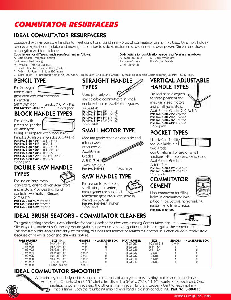
©Essex Group, Inc., 1998
COMMUTATOR RESURFACERSIDEAL COMMUTATOR RESURFACERSEquipped with various style handles to meet conditions found in any type of commutator or slip ring. Used by simply holdingresurfacer against commutator and moving it from side to side as motor turns over under its own power. Dimensions shownare length x width x thickness.Code letters for different grade resurfacer are as follows: Code letters for combination grade resurfacer are as follows:X- Extra Coarse - Very fast cutting. A - Medium/Finish G - Coarse/MediumC - Coarse - Fast cutting. B - Coarse/Finish H - Medium/PolishM - Medium - For general use. D - Finish/PolishF - Finish - Used after above three grades.P - Polish - For burnish finish (220 grain).E - Extra Polish - For production finishing (320 Grain). Note: Both Part No. and Grade No. must be specified when ordering, i.e. Part No.S80-155X.
PENCIL TYPEFor fans signal motors auto generators and other fractional HP motors.5/8”X 3/8” X 6” Grades X-C-M-F-P-EPart Number S-80-075* * Add grade
VERTICAL ADJUSTABLEHANDLE TYPES10" rod handle adjusts to three positions for medium sized motors and small generators. Available in Grades X-C-M-F-P.Part No. S-80-215* 2"x2"x2"Part No. S-80-224* 3"x2"x2"Part No. S-80-234* 3"x3"x2"Part No. S-80-243* 4”x3”x2” * Add grade
SMALL MOTOR TYPEMedium grade stone on one side anda finish device grade stone on other end of handle. Available in Grades A-B-D-G-H 3/4"x1/2" x3/8" Part No. S-80-12* * Add grade
SAW HANDLE TYPEFor use on large motors, small rotary converters, motor generator sets, and telephone generators. Available ingrades X-C-M-F-P.Part No. S-80-362* 4"x3"x2"* Add grade
POCKET TYPESHandy 2-in-1 utilitytool available in alltwo-gradecombinations. For use on smallfractional HP motors and generators.Available in Grades A-B-D-G-HPart No. S-80-112* 2"x1 "x6"Part No. S-80-137* 2"x1 "x8"*Add grade
DOUBLE SAW HANDLETYPESFor use on large rotary converters, engine driven generatorsand motors. Provides two handcontrols. Available in Grades X-C-M-F-P.Part No. S-80-407* 4"x8"x3"Part No. S-80-419* 5"x7"x3"Part No. S-80-432* 5"x9"x3"
BLOCK HANDLE TYPESFor use with precision grinder or lathe type truing. Equipped with wood blackhandles Available in Grades X-C-M-F-P.Part No. S-80-454* 1" x 1-1/2" x 5"Part No. S-80-461* 1" x 2" x 5"Part No. S-80-468* 1" x 2-1/2" x 5"Part No. S-80-482* 1" x 1-1/2" x 8" Part No. S-80-475* 2" x 2" x 5 Part No. S-80-489* 1-1/2" x 2-1/2" x 8"Part No. S-80-496* 2" x 2” x 8”* Add grade
IDEAL COMMUTATOR SMOOTHIE®
A resurfacing tool designed to smooth commutators of auto generators, starting motors and other similar equipment. Consists of an 8-1/2" plastic handle with a 5/16" x 7/8" x 1 1/16" resurfacer on each end. One
resurfacer is polish grade and the other is finish grade. Handle is properly bent to reach not any motor frame. Both the resurfacing material and handle are non-conducting. Part No. S-80-033
COMMUTATORCEMENTNon-conductor for fillingholes in commutator bars,pitted mica. Strong, non-shrinking,resists fire, oils, and acids.Part No. TI-54-007
STRAIGHT HANDLETYPESUsed primarily on inaccessible commutators in small-enclosed motors Available in gradesX-C-M-F-P.Part No. S-80-155* 1"x1"x1"Part No. S-80-165* 1"x1"x2"Part No. S-80-184* 2"x1"x2"Part No. S-80-193* 3"x1"x2"* Add grade
110
IDEAL BRUSH SEATORS - COMMUTATOR CLEANERSThis gentle acting abrasive is very effective for seating carbon brushes and cleaning Commutators and Slip Rings. It is made of soft, loosely bound grain that produces a scouring effect as it is held against the commutator. The abrasive wears away sufficiently for cleaning, but does not remove or scratch the copper. It is often called a "chalk" storebecause of its white color and chalk-like texture.
PART NUMBER SIZE (IN.) GRADES NUMBER/PER BOX PART NUMBER SIZE GRADES NUMBER/PER BOXTI-23-001 1/4x1/4x4 3/4 M-H 12 TI-23-027 1 1/2x1x4 3/4 S-M-H 1TI-23-002 1/2x1/4x4 3/4 M-H 6 TI-23-035 1x1x4 3/4 S 4TI-23-003 3/8x3/8x4 3/4 M-H 4 TI-23-036 2x1x4 3/4 S 2TI-23-004 1/2x3/8x4 3/4 S-M-H 4 TI-23-037 2x2x2 S 2TI-23-005 1/2x1/2x4 3/4 S-M-H 2 TI-23-039 3x2x4 S 2TI-23-006 5/8x1/2x4 3/4 S-M-H 2 TI-23-041 3x2x6 S 2TI-23-007 3/4x1/2x4 3/4 S-M-H 2 TI-23-042 3x2x8 S 2TI-23-008 1 1/8x5/8x4 3/4 SM-H 1

The Complete Puller consists of internal extractor No. 21 and counter stay No. 22
Counter Stays No. 22/1-22/3 for use with internal extractors No. 21/0-21/9PART NO. SUITABLE FOR NO. CONNECTION TO INTERNAL EXTRACTOR* WEIGHT LBS.TGP-22/l 21/01-21/5 21/0-2 with reduction collar
21/3-5 without reduction collar 1 1/2TGP-22/2 21/3-21/8 21/3-5 with reduction collar
21/6-8 without reduction collar 3TGP-22/3 21/9 By connecting nut 7 1/2
*The counter stays No.22/1 and 22/2 are each supplied with a threaded reduction collar;application in accordance with the above table.
©Essex Group, Inc., 1998
HAND TOOLS & SHOP SUPPLIES
111
PORTABLE HYDRAULIC PULLEYPULLERPortable and easy to operate, it quickly removes practically any object from a shaft. Sturdily constructed yet reasonably priced, it has added safety features like remote control and Quicklink Chain Attachment. Pressure is supplied tothe hydraulic ram by either an easily operated hand pumpor an electrically operated pump. Three simpleadjustments set the puller to the dimensions required. Thebeam, arms, ram and pump can be removed from thepuller stand for overhead or other special uses. Eliminatesthe need for crow bars, wedges, torches, etc.
SPECIFICATIONSMAXIMUM MAXIMUM DIMENSIONS SHIP
PULLER DIAMETER (IN.) FACE (IN.) H(IN.) W(IN.) L(IN.) WEIGHT
8 Ton 22 24 40 26 36 140 lbs.
20 Ton 32 36 42 34 48 460 lbs.
60 Ton 42 48 48 46 60 820 lbs.
100 Ton 48 48 48 46 60 1060 lbs.
Part No. THP-8H 8 Ton Manual Hydraulic Puller completewith Quicklink Chain Attachment.Part No. THP-20H 20 Ton Manual Hydraulic Puller withQuicklink Chain Attachment and set of Ram Adapters.Part No. THP-60H 60 Ton Manual Hydraulic Puller withQuicklink Chain Attachment and set of Ram Adapters.Part No. THP-2OHEP 20 Ton Hydraulic Puller with ElectricPump, with Quicklink Chain Attachment and set ofRam Adapters.Part No. THP-6OHEP 60 Ton Hydraulic Puller with ElectricPump, with Quicklink Chain Attachment and set ofRam Adapters.Part No. THP-1OOHEP 100 Ton Hydraulic Puller withElectric Pump, with Quicklink Chain Attachment and set ofRam Adapters.
ACCESSORIESPart No. THP-80 Quicklink Chain for 8 ton model.6' of 3/8" chain. Part No. THP-200 Quicklink Chain for 20 ton models.8' of 3/8" chain.Part No. THP-600 Quicklink Chain for 60 ton models.10' of 1/2" chain.Part No. THP-2OEPK 20 Ton Electric Pump Kit. * Part No. THP-6OEPK 60 Ton Electric Pump Kit. * Part No. THP-RA-20 Set of 10 Adapters for 20ton models. Part No. THP-RA-60 Set of 10 Adapters for 60ton models. Part No. THP-RA-100 Set of 10 Adapters for 100ton models.*The electric pump is wired for 115V/10/60 Hz. Thispump is available in easy-to-install kit form for adaptationto all 20, 50 and 60 ton pullers manufactured since 1945.
FOB DAVENPORT, IOWA
KUKKO UNIVERSAL BEARINGEXTRACTORS NO. 21 AND 22The ideal tool for removing ball bearings, ball races,sleeves, or bushes.
The excellent gripping effect ensures safe holdand easy extraction of the bearings, even if thebearing fits very closely to the rear ofits housing.
Method of OperationInsert the internal extractor No. 21 into thebore of the ball bearing. Tightening the nut Bcauses jaws C to expand and lips D to bepressed behind the rounded edges of thebearing race.
The counter Stay No. 22 is placed on thehousing and spindle E screwed onto theSpindle A of the internal extractor.
Now handle G is held firmly and nut F on thecounter stay is tightened, thus effectingextracting action.
During extraction retighten nut B on theinternal extractor.
INTERNAL EXTRACTORS NO. 21/0-21/9PART NUMBER INCHES MM WEIGHT
TGP-21/0 13/64 - 15/64 5 - 6 3 oz.TGP-21/00 15/64 - 5/16 6 - 8 3 oz.TGP-21/01 5/16-13/32 8 - 10 3 oz.TGP-21/02 13/32 - 1/2 10 - 12 3 oz.TGP-21/1 1/2 - 9/16 12 - 14.5 4 oz.TGP-21/2 9/16- 23/32 14.5 - 18.5 4 oz.TGP-21/3 23/32 - 29/32 18.5 - 23.5 8 oz.TGP-21/4 29/32 - 1 3/16 23.5 - 30 9 oz.TGP-21/5 1 3/16-1 15/32 30 - 37 14 oz.TGP-21/6 1 15/32 - 1 13/16 37 - 46 1 1/2 lbs.TGP-21/7 1 13/16 - 2 7/32 46 - 56 2 3/4 lbs.TGP-21/6 2 7/32 - 2 3/4 56 - 70 3 1/4 lbs.TGP-21/9 2 3/4 - 3 15/16 70 - 100 6 lbs.

Kukko manufactures a complete line of pullers, extractors,separators, and repair parts for their equipment. Many items available in complete sets.
©Essex Group, Inc., 1998
HAND TOOLS & SHOP SUPPLIES
112
NO. 11 THREE ARM PULLERSA well tried industrial puller forremoving large pulleys, gearwheels, and similar heavycomponents. For internal andexternal operation. Extremelystrong pulling arms have largecontact surfaces so that carefulremoval without damage isaccomplished. Longer arms to20” depth are available.
Part No. TGP-11/0-A 15” Capacity with 8” Gripping Depth.Shipping Weight approx. 30 lbs.Part No. TGP-11/1-A 21” Capacity with 8” Gripping Depth.Shipping Weight approx. 48 lbs.Part No. TGP-11/2-A 26” Capacity with 8” Gripping Depth.Shipping Weight approx. 59 lbs.
NO. 20 TWO ARM PULLERS
NO. 41 & 42 PULLERSUseful models for removing batteryterminals and other light puller jobs.
Part No. TGP-41 Two Arm Puller 2 9/16”Capacity with 2 9/16” Gripping Depth. Shippingweight approximately 5 oz.Part No. TGP-42 Three Arm Puller 2 9/16”Capacity with 2 9/16” Gripping Depth. Shipping weightapproximately 9 oz.
NO. 12 THREE ARM PULLERSSturdy pullers with excellent grippingaction for removing ball bearings, gearwheels, and pulleys. The slender armsenable this puller to be used in placeswhich are not easily accessible. Thewrench fixes the arms to the requiredwidth in such a way so as to preventthe arms slipping off.
Part No. TGP-12/1 3 1/8” Capacity with 3 1/8” Gripping Depth.Shipping weight approximately 2 1/2 lbs.Part No. TGP-12/2 4 3/8” Capacity with 5” Gripping Depth.Shipping weight approximately 4 lbs.Part No. TGP-12/3 8” Capacity with 6 1/2” Gripping Depth.Shipping weight approximately 7 lbs.
Part No. TGP-20/2 6” Capacity with 6” Gripping Depth.Shipping weight approximately 6 lbs.Part No. TGP-20/20 8” Capacity with 6” Gripping Depth.Shipping weight approximately 7 1/4 lbs.Part No. TGP-20/3 10” Capacity with 8” Gripping Depth.Shipping weight approximately 15 lbs.Part No. TGP-20/30 14” Capacity with 8” Gripping Depth.Shipping weight approximately 19 lbs.Part No. TGP-20/4 21” Capacity with 8” Gripping Depth.Shipping weight approximately 28 lbs.Part No. TGP-20/5 30” Capacity with 16” to 27” GrippingDepth. Shipping weight approximately 90 lbs.
Well constructed, sturdy puller withlarge pulling surfaces and extra thinclaws for use in restricted position. Forboth internal and external pulling.Longer arms to 20” depth are available.
Part No. TGP-20/1 3” Capacity with 4”Gripping Depth. Shipping weightapproximately 2 lbs.Part No. TGP-20/10 5” Capacity with 4” Gripping Depth.Shipping weight approximately 2 1/2 lbs.
NO. 205 & 206 PULLERSVery powerful pullers for pulling gears and pulleys.Adjustable fixing of the arms secures correct fitting to therequired gripping depth. Arms automatically tightentighten when nut is turned.
TWO ARM PULLERSPart No. TGP-205/01 6” Capacity with 6” GrippingDepth. Shipping weight approximately 2 lbsPart No. TGP-205/02 8 3/4” Capacity with 8 3/4”Gripping Depth. Shipping weight approximately 5 lbs.Part No. TGP-205/1 12” Capacity with 9 1/2”Gripping Depth. Shipping weight approximately 12 lbs.Part No. TGP-205/2 14” Capacity with 16” Gripping Depth. Shipping weight approximately15 lbs.
THREE ARM PULLERSPart No. TGP-206/01 6” Capacity with 6” GrippingDepth. Shipping weight approximately 3 lbs.Part No. TGP-206/02 8 3/4” Capacity with 8 3/4”Gripping Depth. Shipping weight approximately 7 lbs.Part No. TGP-206/1 12” Capacity with 9 1/2” GrippingDepth. Shipping Weight approx. 15 lbs.Part No. TGP-206/2 14” Capacity with 16” GrippingDepth. Shipping Weight approx. 20 lbs.
KUKKO BALL BEARING EXTRACTOR & PULLERS
BALL BEARING INSTALLER KITInstalls ball bearings fast and easy without damage to seals or flanges. Sleeves are made of steel, heat treated and hardened for use with arbor press or mallet, admium plated for protection against rust, and knurled for easy handling. Sleeve made about .025” larger than bore of bearing, and passes easily over shaft,providing a perfectly lined installation. Outside diameter fitsinner race of bearing. Long enough to use on standardNEMA shaft extension. Ranges from 200 Series ball bearings(10mm I.D.) to 209 Series (45mm I.D.)Part No. TBI-10 Set of 10 sleeves for bearings 10 to45mm bore.
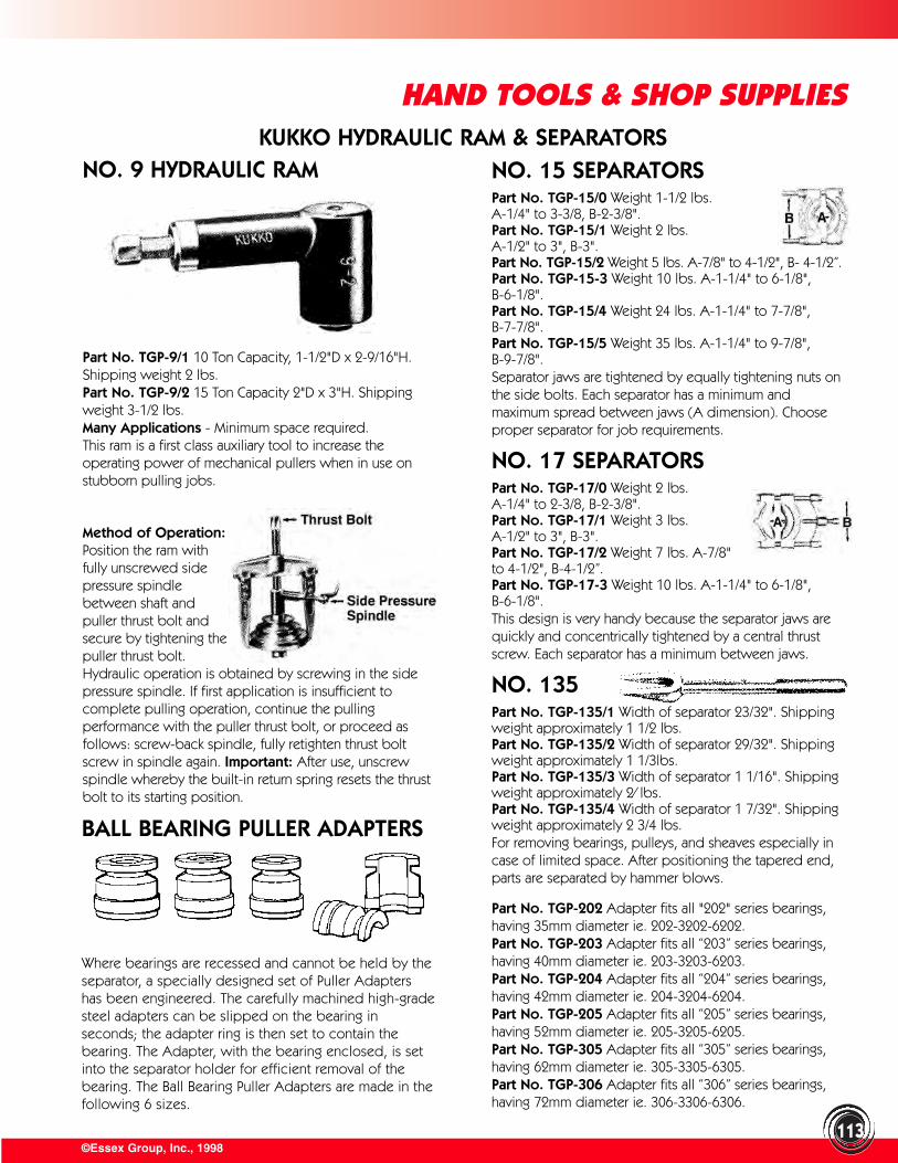
113©Essex Group, Inc., 1998
KUKKO HYDRAULIC RAM & SEPARATORSNO. 9 HYDRAULIC RAM
Part No. TGP-9/1 10 Ton Capacity, 1-1/2"D x 2-9/16"H.Shipping weight 2 lbs.Part No. TGP-9/2 15 Ton Capacity 2"D x 3"H. Shippingweight 3-1/2 lbs.Many Applications - Minimum space required.This ram is a first class auxiliary tool to increase the operating power of mechanical pullers when in use onstubborn pulling jobs.
NO. 15 SEPARATORSPart No. TGP-15/0 Weight 1-1/2 lbs. A-1/4" to 3-3/8, B-2-3/8".Part No. TGP-15/1 Weight 2 lbs.A-1/2" to 3", B-3".Part No. TGP-15/2 Weight 5 lbs. A-7/8" to 4-1/2", B- 4-1/2”.Part No. TGP-15-3 Weight 10 lbs. A-1-1/4" to 6-1/8", B-6-1/8".Part No. TGP-15/4 Weight 24 lbs. A-1-1/4" to 7-7/8",B-7-7/8".Part No. TGP-15/5 Weight 35 lbs. A-1-1/4" to 9-7/8", B-9-7/8".Separator jaws are tightened by equally tightening nuts onthe side bolts. Each separator has a minimum and maximum spread between jaws (A dimension). Chooseproper separator for job requirements.
NO. 17 SEPARATORSPart No. TGP-17/0 Weight 2 lbs. A-1/4" to 2-3/8, B-2-3/8".Part No. TGP-17/1 Weight 3 lbs.A-1/2" to 3", B-3".Part No. TGP-17/2 Weight 7 lbs. A-7/8"to 4-1/2", B-4-1/2”.Part No. TGP-17-3 Weight 10 lbs. A-1-1/4" to 6-1/8",B-6-1/8".This design is very handy because the separator jaws arequickly and concentrically tightened by a central thrustscrew. Each separator has a minimum between jaws.
NO. 135Part No. TGP-135/1 Width of separator 23/32". Shippingweight approximately 1 1/2 lbs. Part No. TGP-135/2 Width of separator 29/32". Shippingweight approximately 1 1/3lbs. Part No. TGP-135/3 Width of separator 1 1/16". Shippingweight approximately 2⁄ lbs. Part No. TGP-135/4 Width of separator 1 7/32". Shippingweight approximately 2 3/4 lbs.For removing bearings, pulleys, and sheaves especially incase of limited space. After positioning the tapered end,parts are separated by hammer blows.
Method of Operation:Position the ram withfully unscrewed sidepressure spindlebetween shaft andpuller thrust bolt andsecure by tightening thepuller thrust bolt.Hydraulic operation is obtained by screwing in the sidepressure spindle. If first application is insufficient tocomplete pulling operation, continue the pullingperformance with the puller thrust bolt, or proceed asfollows: screw-back spindle, fully retighten thrust boltscrew in spindle again. Important: After use, unscrewspindle whereby the built-in return spring resets the thrustbolt to its starting position.
BALL BEARING PULLER ADAPTERS
Where bearings are recessed and cannot be held by theseparator, a specially designed set of Puller Adaptershas been engineered. The carefully machined high-gradesteel adapters can be slipped on the bearing inseconds; the adapter ring is then set to contain thebearing. The Adapter, with the bearing enclosed, is setinto the separator holder for efficient removal of thebearing. The Ball Bearing Puller Adapters are made in thefollowing 6 sizes.
Part No. TGP-202 Adapter fits all "202" series bearings,having 35mm diameter ie. 202-3202-6202.Part No. TGP-203 Adapter fits all “203” series bearings,having 40mm diameter ie. 203-3203-6203.Part No. TGP-204 Adapter fits all “204” series bearings,having 42mm diameter ie. 204-3204-6204.Part No. TGP-205 Adapter fits all “205” series bearings,having 52mm diameter ie. 205-3205-6205.Part No. TGP-305 Adapter fits all “305” series bearings,having 62mm diameter ie. 305-3305-6305.Part No. TGP-306 Adapter fits all “306” series bearings,having 72mm diameter ie. 306-3306-6306.
HAND TOOLS & SHOP SUPPLIES

©Essex Group, Inc., 1998114
HAND TOOLS & SHOP SUPPLIES
Part No. TRBH-805 Induction Bearing Heater. Includes setof 3 cross-bars listed in specs.
ACCESSORIES:Part No. TRBH-1O Extra small bar used with 203 and 204bearings size 1/2" x 1/2".Part No. TST-213 Tempulstik Temperature Rating Marker.Rated at 213ºF.Part No. TRBH-SC238 2-3/8" Raising Blocks.
APPROXIMATE HEATING TIMES FOR TYPICAL BEARINGSBEARING O.D. (IN.) WIDTH (IN.) TIME
6204 1.8504 .5512 1 min.6209 3.3465 .7480 1 min.6309 3.9370 .9843 1 min. 45 sec.6310 4.3307 1.0630 2 min.6313 5.5118 1.2992 4min.6315 6.2992 1.4567 4 min.6319 7.8740 1.7717 8min.
Easy to use. Mark with Thermo Crayon. When crayon markmelts, slip bearing on shaft. Open, shielded and sealedbearings mounted without damage to lubricants. Safe, nodanger of fire or explosion hazard. Heating time for smallbearings is approximately two minutes, medium size fiveminutes, large bearings ten minutes or as required.
SPECIFICATIONS:110 volts AC, 725 watts. Weight 8 lbs. Height 10". Mountsany bearing or gear with 3/4" to 8" bore. Comes completewith six foot heavy duty cord and switch, plus ThermoCrayon. Constructed of aluminum for fast heat transfer.Also available in 240V AC.
Part No. TBH-160 Model B Bearing Heater for bearings to5 3/4" bore.Part No. TBH-170 Model C Heavy Duty Bearing Heater forbearings to 5 3/4" bore.Part No. TBH-190 Model Super D Bearing Heater withtemperature control for bearings to 8" bore.
Note: Larger Bearing Heaters are available. Please contactyour local branch for information and brochure.
QUICK, POSITIVE BEARINGINSTALLATIONSPECIFICATIONS: GROSS WEIGHT: 50 pounds.HEIGHT: 8-3/4 inches. LENGTH: 10 inches. THROATWIDTH: 4-3/4 inches. THROAT HEIGHT under removablebars: 3-3/4 inches.LARGE BAR: (cross-sections) 2" x 2" MEDIUM BAR: 1-1/4" x 1-1/4" SMALL BAR: 3/4" x 3/4" included.OPERATING CURRENT: 110 volts, 17 amps. Rated for 20minute intermittent duty. Handles bearing sizes up to 10-1/2" O.D., 4-3/8" wide. For larger sizes, Part No. TRBH-BC and Part No. TRBH-BCS, ask for specifications.The use of Reco induction bearing heaters can now giveyou a superior method of applying heat to bearings undercontrolled conditions. Bearings can quickly be brought toproper heat while still in their wrapper. Protection fromhazards, burns and fire danger.
RECO INDUCTION BEARINGHEATER
CONE THERMO BEARING HEATERS

©Essex Group, Inc., 1998
HAND TOOLS & SHOP SUPPLIESMARTINDALE UNIVERSAL
Including 4 "V" Cutters or 8 SawsPart No. TUC-20 Undercutter with both slot guides anduniversal motor 115 or 230 V (specify which).Part No. TUC-21 Undercutter with both slot guides andSwivel Connection, for use with your motor (specifyshaft diameter).Part No. TUC-22 Undercutter with both slot guides andAir Motor.Part No. TUC-14-C Core (replacement for flexible shaft).Part No. TUC-14-S Sheath (replacement for flexible shaft).Part No. TUC-16-HS Saws 1/2" O.D. 3/16" hole.Part No. TUC-17-VHS Cutters 1/2" O.D. 3/16" hole.
Universal in four ways; has universal electric motor or airmotor; can be used on commutators of any diameter, cutseither "U" or "V" slots. The handles may be set at mostconvenient operating angle. The 1/5 HP electric motor ismounted on a swivel base, or may be suspended by itshandle. Drive shaft is extremely flexible and light, thoughsturdy. (No.14, 1/4" diameter, 3 ft. long.) Net weight with1/5 HP electric motor, 12-1/2" lbs., without motor, 2-1/4lbs., with Air Motor, 2-1/2 lbs. Shipping weight with electricmotor, 18 lbs., without motor, 3-1/2 lbs., with Air Motor,4-1/2 lbs. Special telephone machine showing UniversalUndercutter with angle slot guide for use on communtatorsup to 7" diameter. The 1/2" diameter saw allows cutting towithin 1/4" of riser.
MARTINDALE JIFF-V UNDERCUTTER Part No. TUC-J-40 Martindale Jiff-V Undercutter, 115 or230 V, including six Jiff-V Files (High-Carbon Steel).Part No. TUC-J-41 Martindale Jiff-V Undercutter, 115 or230 V, including six Jiff-U Saws (specify thickness).Part No. TUC-J-42 Extra Jiff-V Files, per dozen.Part No. TUC-J-43 Extra Jiff-V Saws, per dozen.
Handy Commutator Slotting Files have always been popularfor undercutting mica and are still recommended for usewhere there is not enough undercutting to justify thepurchase of a motor-driven undercutting machine.
The motor-driven Jiff-V Undercutter cuts a similar V slotquickly. Also available for this undercutter are Jiff-U saws,which operate the same as the file except they make a U-shaped cut and are available in the following 7 thicknesses:.015", .020", .026", .030", .032", .035" and .040".
The Jiff-V does rapid work and cuts clear up to the riser. Itcan be used on commutators of any size without removingthe brush arms.
The Jiff-V Undercutter has proven especially adaptable tounder-cutting motors which must be kept running most ofthe time, such as elevator motors.
Even an inexperienced operator can use the Jiff-V withoutdanger or damaging commutator bars.
115

©Essex Group, Inc., 1998
HAND TOOLS & SHOP SUPPLIES
116
MARTINDALE HEAVY-DUTY BENCH-TYPE UNDERCUTTER MODEL H-9
MARTINDALE LATHE-TYPEUNDERCUTTER
Model H-9 uses either High-Speed Steel or Carbide Sawsand V-cutters; handles armatures from the small sizes upto 17" diameter. This includes a range of sizes too large forModel HV-3 and not large enough to necessitate anUndercutter as large as the Shop-Type.FEATURES:Spindle speed easily changed for H.S. Steel or Carbide Saws.Cutting Head Carriage travels freely on ball-bushings onhardened steel rods; entire carriage tips to the side to facilitatelowering armatures onto the V-supports. Adjustmentprovided for aligning to skewed commutator bars.Rear Armature Support adjusted horizontally by a lead screw.Two spindles available (with 3/16" arbor for 1/2" diametersaws, or with 5/16" arbor for saws 7/8" diameter orlarger). Machine comes equipped with one spindle;other at extra cost.
SPECIFICATIONSMaximum between centers 21", V-supports 35".V-supports vertically adjustable.Takes armatures 12" diameter on centers or 17" on V-supports.Handles commutators up to same diameters as armatures.Saw lifts out of slot on return stroke.Stops limit saw travel.Fine screw adjustment for depth of cut.Motor: 1/2 HP, 3450 RPM.Dimensions with bench: 4' L x 2' W x 5' H.
Part No. TUC-H-9 (115 or 230 volt, 60 Hz. - specifywhich), extra Pulley and Belt, one Saw Spindle (3/16" or5/16" arbor - specify which) including bench and light.Part No. TUG-H-10 Extra Saw Spindle (3/16" or 5/16" arbor).Part No. TUG-H-l1 Dust Collector with 2 hoods. Weight (incl. Dust Collector) - Net 280 lbs.; Ship., 400 lbs.
A spring between hardened washers under the pulleyallows the spindle to float up or down and follow anexisting slot that is being re-cut. If a fixed spindle is desired,the spring can be removed and the pulley turned over.Two spindles are furnished: one for 7/8" x 3/16" sawswhich turn at 2400 RPM, and one for 1/2" x 3/16" saws(cuts closer to riser) which turns at 5400 RPM.To change spindles remove both pulleys - slide out onespindle and slide in the other. Put the 2" pulley on the3/16" spindle, or the 3" pulley on the 5/16" spindle. Theother pulley goes on the motor.Including 4 "V" Cutters or 8 SawsPart No. TUG-50 Lathe Type Undercutter (115 or 230 volt,60 Hz. - specify which) complete with slide carriage andboth spindles.Part No. TUG-51 Lathe Type Undercutter (115 or 230 volt,60 Hz. - specify which) for attaching directly to lathe andwith both spindles.
SAWS AND CUTTERSHIGH SPEED STEEL O.D. (IN.) HOLE (IN.)Part No. TUG-16-HS Saws 1/2 3/16Part No. TUG-17-VHS Cutters 1/2 3/16Part No. TUG-75-HS Saws 7/8 5/16Part No. TUC-75-VHS Cutters 7/8 5/16Part No. TUG-85-HS Saws 1 5/16Part No. TUG-85-VHS Cutters 1 5/16
CARBIDE O.D. (IN.) HOLE (IN.)Part No. TUG-16-TC Saws 1/2 3/16Part No. TUG-17-VTC Cutters 1/2 3/16 Part No. TUC-75-TG Saws 7/8 5/16Part No. TUG-75-VTC Cutters 7/8 5/16 Part No. TUG-85-TC Saws 1 5/16Part No. TUC-85-VTC Cutters 1 5/16
FOB CLEVELAND, OHIO (All Items on Page)
EXTRA SAWS AND CUTTERSHIGH SPEED STEEL O.D. (IN.) HOLE (IN.)
Part No. TUC-75-HS Saws 7/8 5/16Part No. TUC-75-VHS Cutters 7/8 5/16Part No. TUG-16-HS Saws 1/2 3/16Part No. TUG-17-VHS Cutters 1/2 3/16Specify voltage desired.
The Lathe-Type Undercutter can be quickly attached inplace of the tool post of any lathe. It can be mounteddirectly on the cross-slide, or on the slide carriage whichis then mounted on the cross-slide.The Slide Carriage is lever operated and is much fasterthan using the lathe traverse control. Travel is 11" withadjustable stops at both ends. A skewed bar adjustmentis provided at the right end.Both horizontal and vertical commutators can be undercut.As undercutting is done from the side of the commutator,the saw or V-cutter is set level with the lathe centers.Undercutter is powered by a 1/2 HP motor and useshigh-speed steel saws or V-cutters.
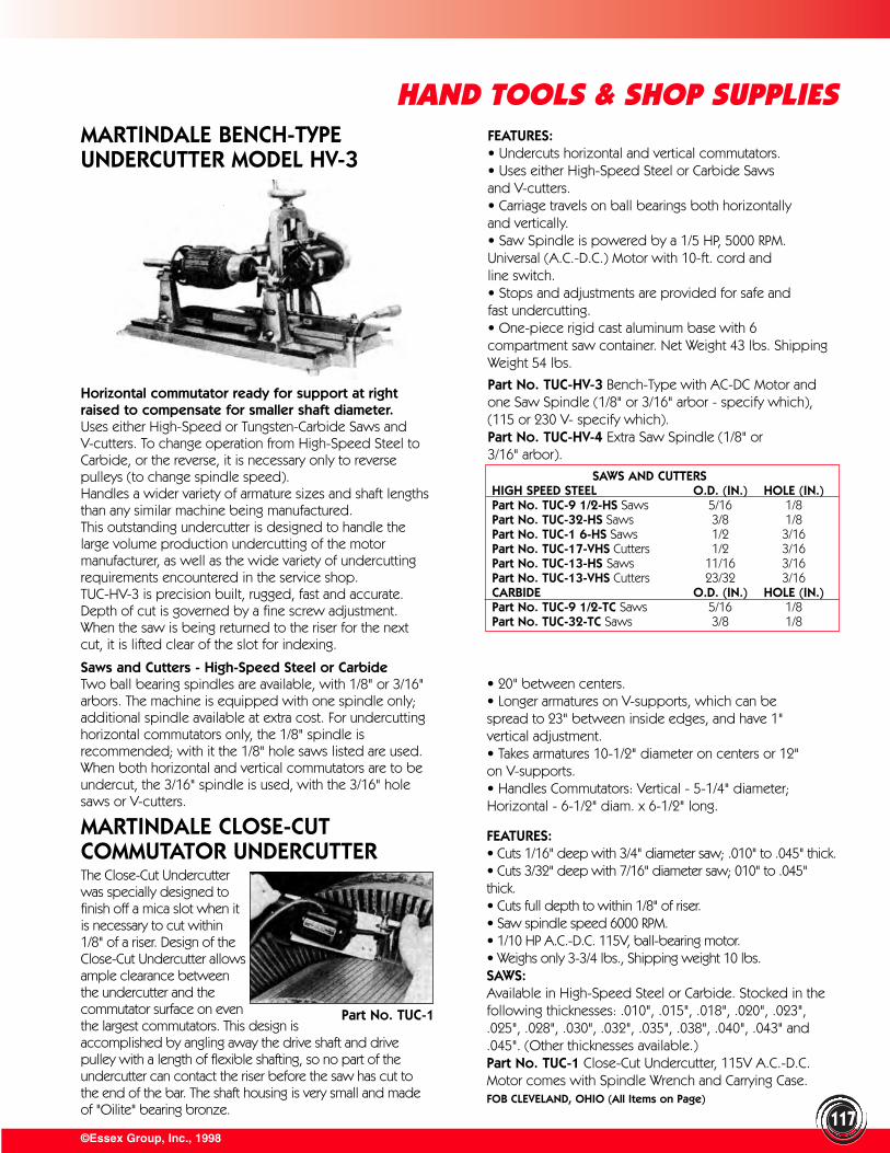
FEATURES:• Cuts 1/16" deep with 3/4" diameter saw; .010" to .045" thick.• Cuts 3/32" deep with 7/16" diameter saw; 010" to .045"thick.• Cuts full depth to within 1/8" of riser.• Saw spindle speed 6000 RPM.• 1/10 HP A.C.-D.C. 115V, ball-bearing motor.• Weighs only 3-3/4 lbs., Shipping weight 10 lbs.SAWS:Available in High-Speed Steel or Carbide. Stocked in thefollowing thicknesses: .010", .015", .018", .020", .023",.025", .028", .030", .032", .035", .038", .040", .043" and.045". (Other thicknesses available.)Part No. TUC-1 Close-Cut Undercutter, 115V A.C.-D.C.Motor comes with Spindle Wrench and Carrying Case.FOB CLEVELAND, OHIO (All Items on Page)
The Close-Cut Undercutterwas specially designed tofinish off a mica slot when itis necessary to cut within1/8" of a riser. Design of theClose-Cut Undercutter allowsample clearance betweenthe undercutter and thecommutator surface on eventhe largest commutators. This design isaccomplished by angling away the drive shaft and drivepulley with a length of flexible shafting, so no part of theundercutter can contact the riser before the saw has cut tothe end of the bar. The shaft housing is very small and madeof "Oilite" bearing bronze.
©Essex Group, Inc., 1998
HAND TOOLS & SHOP SUPPLIES
117
MARTINDALE BENCH-TYPEUNDERCUTTER MODEL HV-3
MARTINDALE CLOSE-CUTCOMMUTATOR UNDERCUTTER
Horizontal commutator ready for support at rightraised to compensate for smaller shaft diameter.Uses either High-Speed or Tungsten-Carbide Saws andV-cutters. To change operation from High-Speed Steel toCarbide, or the reverse, it is necessary only to reversepulleys (to change spindle speed).Handles a wider variety of armature sizes and shaft lengthsthan any similar machine being manufactured.This outstanding undercutter is designed to handle thelarge volume production undercutting of the motormanufacturer, as well as the wide variety of undercuttingrequirements encountered in the service shop.TUC-HV-3 is precision built, rugged, fast and accurate.Depth of cut is governed by a fine screw adjustment.When the saw is being returned to the riser for the nextcut, it is lifted clear of the slot for indexing.
Saws and Cutters - High-Speed Steel or CarbideTwo ball bearing spindles are available, with 1/8" or 3/16"arbors. The machine is equipped with one spindle only;additional spindle available at extra cost. For undercuttinghorizontal commutators only, the 1/8" spindle isrecommended; with it the 1/8" hole saws listed are used.When both horizontal and vertical commutators are to beundercut, the 3/16" spindle is used, with the 3/16" holesaws or V-cutters.
FEATURES:• Undercuts horizontal and vertical commutators.• Uses either High-Speed Steel or Carbide Saws and V-cutters.• Carriage travels on ball bearings both horizontally and vertically.• Saw Spindle is powered by a 1/5 HP, 5000 RPM.Universal (A.C.-D.C.) Motor with 10-ft. cord and line switch.• Stops and adjustments are provided for safe and fast undercutting.• One-piece rigid cast aluminum base with 6compartment saw container. Net Weight 43 lbs. ShippingWeight 54 lbs.
Part No. TUC-HV-3 Bench-Type with AC-DC Motor andone Saw Spindle (1/8" or 3/16" arbor - specify which), (115 or 230 V- specify which).Part No. TUC-HV-4 Extra Saw Spindle (1/8" or 3/16" arbor).
• 20" between centers.• Longer armatures on V-supports, which can be spread to 23" between inside edges, and have 1" vertical adjustment.• Takes armatures 10-1/2" diameter on centers or 12" on V-supports.• Handles Commutators: Vertical - 5-1/4" diameter;Horizontal - 6-1/2" diam. x 6-1/2" long.
Part No. TUC-1
SAWS AND CUTTERSHIGH SPEED STEEL O.D. (IN.) HOLE (IN.)Part No. TUC-9 1/2-HS Saws 5/16 1/8Part No. TUC-32-HS Saws 3/8 1/8Part No. TUC-1 6-HS Saws 1/2 3/16Part No. TUC-17-VHS Cutters 1/2 3/16Part No. TUC-13-HS Saws 11/16 3/16Part No. TUC-13-VHS Cutters 23/32 3/16CARBIDE O.D. (IN.) HOLE (IN.)Part No. TUC-9 1/2-TC Saws 5/16 1/8Part No. TUC-32-TC Saws 3/8 1/8
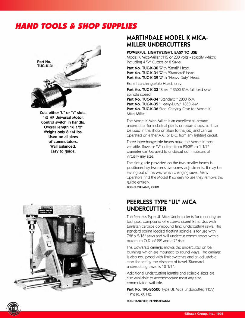
©Essex Group, Inc., 1998118
HAND TOOLS & SHOP SUPPLIESMARTINDALE MODEL K MICA-MILLER UNDERCUTTERSPOWERFUL, LIGHTWEIGHT, EASY TO USEModel K Mica-Miller (115 or 230 volts - specify which)including 4 "V" Cutters or 8 Saws:
Part No. TUC-K-30 With "Small" Head.Part No. TUC-K-31 With "Standard" head.Part No. TUC-K-32 With "Heavy-Duty" Head.
Extra Interchangeable Heads only:
Part No. TUC-K-33 "Small." 3500 RPM full load sawspindle speed.Part No. TUC-K-34 "Standard." 2800 RPM.Part No. TUC-K-35 "Heavy-Duty." 1850 RPM.Part No. TUC-K-36 Steel Carrying Case for Model K Mica-Miller.
The Model K Mica-Miller is an excellent all-aroundundercutter for industrial plants or repair shops, as it canbe used in the shop or taken to the job, and can beoperated on either A.C. or D.C. from any lighting circuit.
Three interchangeable heads make the Model K mostversatile. Saws or "V" cutters from 23/32" to 1-1/4"diameter can be used to undercut commutators ofvirtually any size.
The slot guide provided on the two smaller heads ispositioned by two sensitive screw adjustments. It may beswung out of the way when changing saws. Manyoperators find the Model K so easy to use they remove theguide entirely.FOB CLEVELAND, OHIO
Cuts either 'U" or "V" slots.1/5 HP Universal Motor.
Control switch in handle.Overall length 16 1/2"Weighs only 8 1/4 lbs.
Used on all sizesof commutators.Well balanced.Easy to guide.
PEERLESS TYPE "UL" MICAUNDERCUTTERThe Peerless Type UL Mica Undercutter is for mounting ontool post compound of a conventional lathe. Use withtungsten carbide compound land undercutting saws. Thestandard spring loaded floating spindle is for use with7/8" x 5/16" saws and will undercut commutators with amaximum O.D. of 22" and a 7" riser.
The powered carriage moves the undercutter on ballbushings which are mounted to round ways. The carriageis also equipped with limit switches and an adjustablestop for setting the distance of travel. Standardundercutting travel is 10-1/4".
Additional undercutting lengths and spindle sizes arealso available to accommodate most any size commutator available.
Part No. TPL-86500 Type UL Mica undercutter, 115V,1 Phase, 60 Hz.
FOB HANOVER, PENNSYLVANIA

Part No. TUC-SP-B15Lathe with motorized undercutter and special 26" bed. Handlestruck and bus, as well as passenger car and small motorarmatures. Includes all parts illustrated plus two #240A steelcenters and one #111C carbide tipped tool bit, but does notinclude M-160 motor.SPECIFICATIONS:Space between chucks 22 1/2" maximumChuck capacities 13/64" to 1 1/16"Swing over bed 7 inches Handles commutators to 3 1/2" diameter, 2 1/2" lengthBench space needed 14 1/2" X 28 1/2"
Part No. TUC-B-15 Lathe with Motorized Undercutter.Faster and more convenient than using under-cutter drive belt,also saves cost of belt replacement. Complete as illustrated, butdoes not include M-160 motor.SPECIFICATIONS:Space between chucks 12 1/2" maximumChuck capacities 13/64" to 1 1/16"Swing over bed 7 inchesHandles commutators to 3 1/2" diameter, 2 1/2" lengthBench space needed 14" X 18 3/4"
Part No. TUC-B-10 Lathe with Belt Driven UndercutterUses M-160 motor to turn armature or rotor and to driveundercutter. Undercutter belt molded of special beltcompound. Complete as illustrated, but does not include M-160 motor.SPECIFICATIONS: Same as TUC-B-15.No. M-160 MOTOR, 1/4"HP, 115V 60C, 1725 RPM, CCW facingshaft end. Used on all lathes to turn armature or rotor and onTUC-B-10 to drive undercutter. Not included with lathes. Order separately.FOB WAUKESHA, WISCONSIN
©Essex Group, Inc., 1998119
IDEAL UNIVERSAL MODELUNDERCUTTER
IDEAL SMALL MODELUNDERCUTTER
TRUCUT LATHES ANDUNDERCUTTERS FOR ARMATURESAND ALTERNATORS
For undercutting large or small commutators, without removingbrush riggings. Works in spaces only 2-3/4" wide and to within1/4" of risers. Designed for heavy-duty service in both shop orfield use. 1/4 HP motor connected to cutting spindle. Theadjustable depth gauge, positive lock and roller guide ride inparallel slot in-suring accuracy. Uses 7/8" diameter, 5/16" boresaws and cutters.
Part No. TI-25-029 Undercutter with 1750 RPM, 1/4 HP, 115VAC, 60 Hz motor; hanger and carrying case. Shipping weight 50 lbs.Part No. TI-25-051 Undercutter Head with flexible shaft, lessmotor. Shipping weight 5 lbs.
For undercutting small motor armatures. 1 to 7 inches. Holdercentered, centerless or hollow shaft. Cutter head is removablefor use in lathes or other holding devices. Shipping weight 22 lbs.Uses 1/8" bore saws.1/4"" saw cuts 1/32" deep.9/32" saw cuts 3/64" deep.5/16" saw cuts 1/16" deep.
Part No. TI-25-048 Undercutter with 8000 RPM, 115V A.C.-D.C. motor.FOB SYCAMORE, ILLINOIS
HAND TOOLS & SHOP SUPPLIES
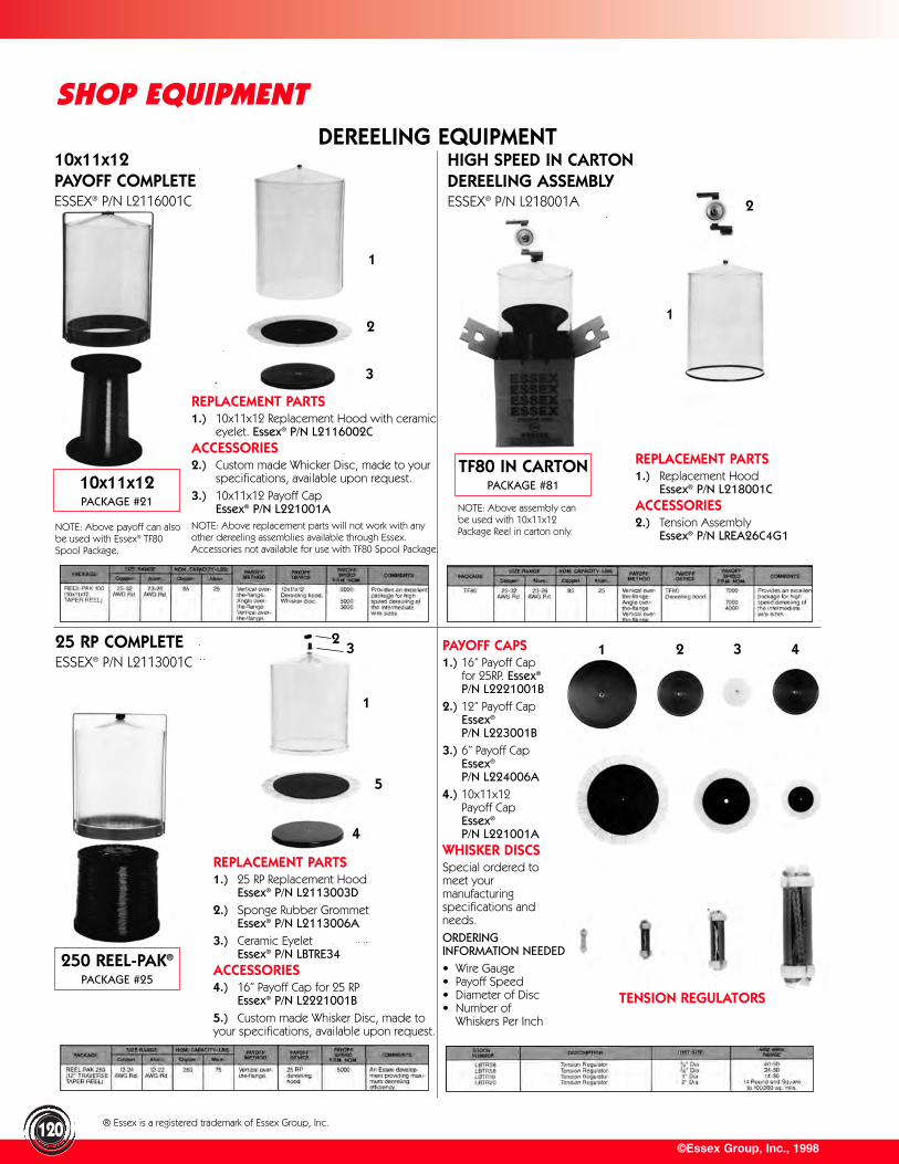
©Essex Group, Inc., 1998
SHOP EQUIPMENT
120
DEREELING EQUIPMENT
1 2 3 4
250 REEL-PAK®
PACKAGE #25
® Essex is a registered trademark of Essex Group, Inc.
1
2
10x11x12PAYOFF COMPLETEESSEX® P/N L2116001C
HIGH SPEED IN CARTONDEREELING ASSEMBLYESSEX® P/N L218001A
25 RP COMPLETEESSEX® P/N L2113001C
1
2
3
1
23
5
4
REPLACEMENT PARTS1.) 25 RP Replacement Hood
Essex® P/N L2113003D2.) Sponge Rubber Grommet
Essex® P/N L2113006A3.) Ceramic Eyelet
Essex® P/N LBTRE34ACCESSORIES4.) 16” Payoff Cap for 25 RP
Essex® P/N L2221001B5.) Custom made Whisker Disc, made toyour specifications, available upon request.
REPLACEMENT PARTS1.) 10x11x12 Replacement Hood with ceramic
eyelet. Essex® P/N L2116002CACCESSORIES2.) Custom made Whicker Disc, made to your
specifications, available upon request.3.) 10x11x12 Payoff Cap
Essex® P/N L221001ANOTE: Above replacement parts will not work with anyother dereeling assemblies available through Essex.Accessories not available for use with TF80 Spool Package.
10x11x12PACKAGE #21
NOTE: Above payoff can alsobe used with Essex® TF80Spool Package.
REPLACEMENT PARTS1.) Replacement Hood
Essex® P/N L218001CACCESSORIES2.) Tension Assembly
Essex® P/N LREA26C4G1
TF80 IN CARTONPACKAGE #81
NOTE: Above assembly canbe used with 10x11x12Package Reel in carton only.
PAYOFF CAPS1.) 16” Payoff Cap
for 25RP. Essex®
P/N L2221001B2.) 12” Payoff Cap
Essex®
P/N L223001B3.) 6” Payoff Cap
Essex®
P/N L224006A4.) 10x11x12
Payoff Cap Essex®
P/N L221001AWHISKER DISCSSpecial ordered to meet yourmanufacturingspecifications andneeds.ORDERINGINFORMATION NEEDED• Wire Gauge• Payoff Speed• Diameter of Disc• Number of • Whiskers Per Inch
TENSION REGULATORS
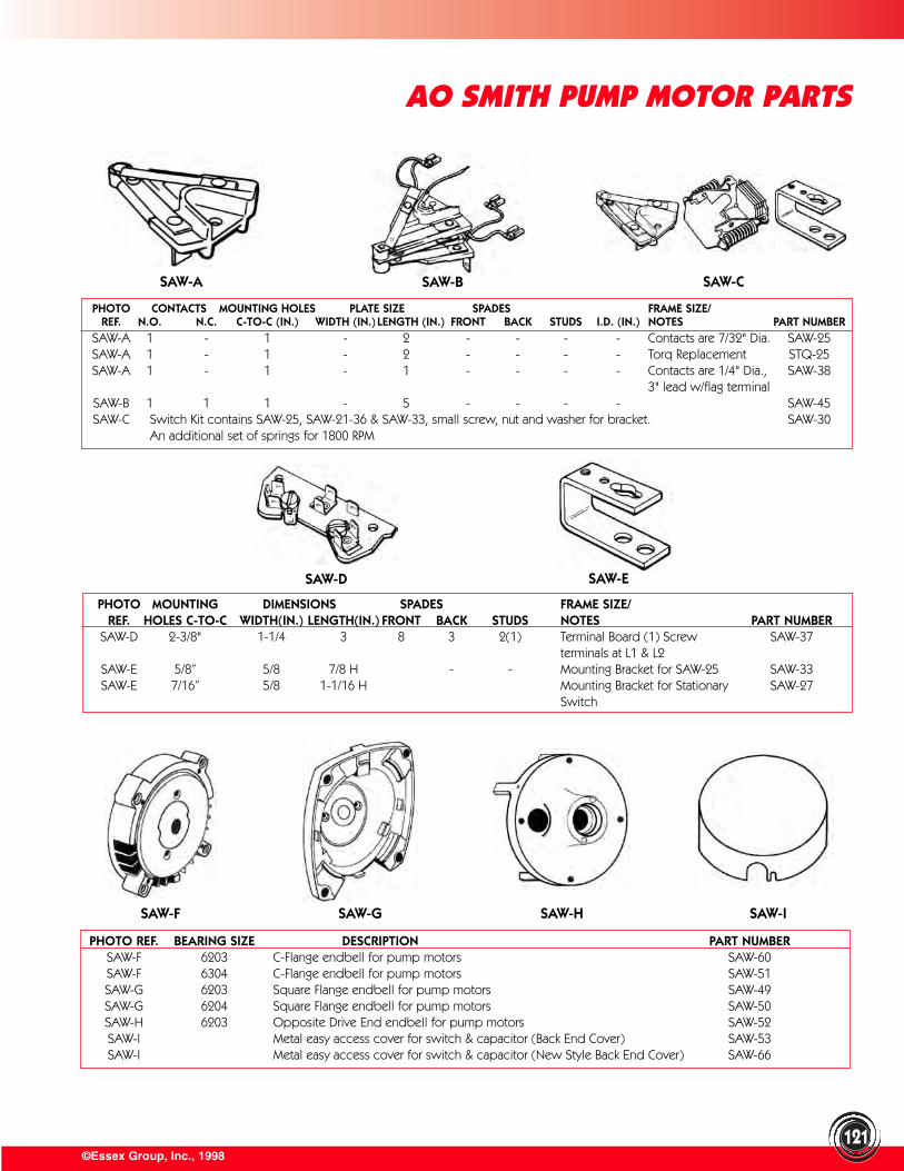
©Essex Group, Inc., 1998121
AO SMITH PUMP MOTOR PARTS
PHOTO CONTACTS MOUNTING HOLES PLATE SIZE SPADES FRAME SIZE/REF. N.O. N.C. C-TO-C (IN.) WIDTH (IN.) LENGTH (IN.) FRONT BACK STUDS I.D. (IN.) NOTES PART NUMBER
SAW-A 1 - 1 - 2 - - - - Contacts are 7/32" Dia. SAW-25SAW-A 1 - 1 - 2 - - - - Torq Replacement STQ-25SAW-A 1 - 1 - 1 - - - - Contacts are 1/4" Dia., SAW-38
3" lead w/flag terminalSAW-B 1 1 1 - 5 - - - - SAW-45SAW-C Switch Kit contains SAW-25, SAW-21-36 & SAW-33, small screw, nut and washer for bracket. SAW-30
An additional set of springs for 1800 RPM
PHOTO MOUNTING DIMENSIONS SPADES FRAME SIZE/REF. HOLES C-TO-C WIDTH(IN.) LENGTH(IN.) FRONT BACK STUDS NOTES PART NUMBER
SAW-D 2-3/8" 1-1/4 3 8 3 2(1) Terminal Board (1) Screw SAW-37terminals at L1 & L2
SAW-E 5/8” 5/8 7/8 H - - Mounting Bracket for SAW-25 SAW-33SAW-E 7/16” 5/8 1-1/16 H Mounting Bracket for Stationary SAW-27
Switch
PHOTO REF. BEARING SIZE DESCRIPTION PART NUMBERSAW-F 6203 C-Flange endbell for pump motors SAW-60SAW-F 6304 C-Flange endbell for pump motors SAW-51SAW-G 6203 Square Flange endbell for pump motors SAW-49SAW-G 6204 Square Flange endbell for pump motors SAW-50SAW-H 6203 Opposite Drive End endbell for pump motors SAW-52SAW-I Metal easy access cover for switch & capacitor (Back End Cover) SAW-53SAW-I Metal easy access cover for switch & capacitor (New Style Back End Cover) SAW-66
SAW-A SAW-B SAW-C
SAW-D SAW-E
SAW-F SAW-G SAW-H SAW-I
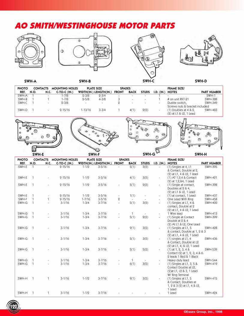
SWH-E SWH-F SWH-G SWH-H
©Essex Group, Inc., 1998
AO SMITH/WESTINGHOUSE MOTOR PARTS
122
PHOTO CONTACTS MOUNTING HOLES PLATE SIZE SPADES FRAME SIZE/REF. N.O. N.C. C-TO-C (IN.) WIDTH(IN.) LENGTH(IN.) FRONT BACK STUDS I.D. (IN.) NOTES PART NUMBER
SWH-A 1 - 1-7/8 2-3/8 2-3/4 - - - 1 - SWH-1SWH-B 1 1 1-7/8 2-5/8 4-3/8 3 - - 1 # on unit R97-21 SWH-388SWH-C 1 - 2-3/8 - - 2 - - - Dustite switch, SWH-349
Screws nuts & bracket includedSWH-D 1 - 2-15/16 1-13/16 3-3/4 1 4(1) 2(2) - (1) Doubles at 4 & 2, SWH-483
(2) at L1 & L2, 1 Lead
PHOTO CONTACTS MOUNTING HOLES PLATE SIZE SPADES FRAME SIZE/REF. N.O. N.C. C-TO-C (IN.) WIDTH(IN.) LENGTH(IN.) FRONT BACK STUDS I.D. (IN.) NOTES PART NUMBER
SWH-E 1 - 2-15/16 1-1/2 3-5/16 - 5(1) 3(2) - (1) Singles at 4, L1 SWH-395& Contact, Double at 2,(2) at L1, 4 & L2, 1 lead
SWH-E 1 - 2-15/16 1-1/2 3-5/16 4(1) 3(2) - (1) AT 1,2,4 & Contact SWH-421(2) at 1,2,&4, 1 Lead
SWH-E 1 - 2-15/16 1-1/2 3-5/16 - 5(1) 2(2) - (1) Single at contact, SWH-398 Doubles at 2 & 4, (2) at L1 & L2, 1 Lead
SWH-E 1 - 2-15/16 1-1/2 3-5/16 - 1(1) - - (1) at contact, 1 Lead SWH-437SWH-F 1 1 2-15/16 1-7/16 3-5/16 2 - - - One Lead With Ring SWH-458SWH-G 1 - 3-1/16 1-3/4 3-7/16 - 5(1) 3(2) - (1) Singles at L1, 4 & SWH-400
contact, Double at 2 (2) at L1, 4 & L2, 1 Lead
SWH-G 1 - 3-1/16 1-3/4 3-7/16 - 1 - - 1 Wire lead SWH-413SWH-G 1 - 3-1/16 1-3/4 3-7/16 - 5(1) 2(2) - (1) Single at Contact SWH-399
Double at 2 & 4(2) At L1 & L2, One Lead
SWH-G 1 - 3-1/16 1-3/4 3-7/16 - 9(1) 3(2) - (1) Singles at L1, 5 SWH-428& contact, Double at 1, 2 & 3 (2) at L1, 4 & L2, 1 Lead
SWH-G 1 - 3-1/16 1-3/4 3-7/16 - 5(1) 3(2) - (1) singles at L1, 4 SWH-436& Contact, Double at L2 (2) at L1, 4, & L2, 1 Lead
SWH-G 1 - 3-1/16 1-3/4 3-7/16 - 5(1) 5(2) - (1) at 1, 2, 3, 4 & SWH-539 Contact (2) at 1, 2, 3, 4 & 6. 2 leads 1 Red & 1 Black
SWH-G 1 - 3-1/16 1-3/4 3-7/16 - 1 - - Heavy duty lead SWH-544SWH-G 1 - 3-1/16 1-3/4 3-7/16 - 6(1) 3(2) - (1) Singles at L1, 3, 5 & SWH-419
Contact Double at L2, (2)at L1, L2 & 3, 1 Lead W/ Ring Terminal
SWH-H 1 1 3-1/16 1-1/2 3-7/16 - 9(1) 3(2) - (1) Singles at L1, 5 SWH-415& Contact, Doubles at 1, 2 & 3 (2) at L1, 4 & L2, 1 Lead
SWH-H 1 1 3-1/16 1-1/2 3-7/16 - - - - 1 Lead SWH-424
SWH-A SWH-B SWH-C SWH-D
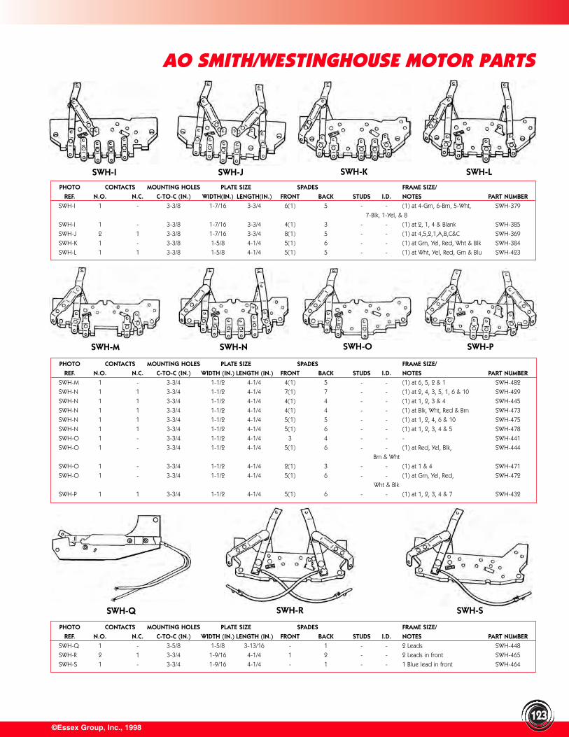
©Essex Group, Inc., 1998123
AO SMITH/WESTINGHOUSE MOTOR PARTS
PHOTO CONTACTS MOUNTING HOLES PLATE SIZE SPADES FRAME SIZE/REF. N.O. N.C. C-TO-C (IN.) WIDTH(IN.) LENGTH(IN.) FRONT BACK STUDS I.D. NOTES PART NUMBER
SWH-I 1 - 3-3/8 1-7/16 3-3/4 6(1) 5 - - (1) at 4-Grn, 6-Brn, 5-Wht, SWH-379
7-Blk, 1-Yel, & 8
SWH-I 1 - 3-3/8 1-7/16 3-3/4 4(1) 3 - - (1) at 2, 1, 4 & Blank SWH-385
SWH-J 2 1 3-3/8 1-7/16 3-3/4 8(1) 5 - - (1) at 4,5,2,1,A,B,C&C SWH-369
SWH-K 1 - 3-3/8 1-5/8 4-1/4 5(1) 6 - - (1) at Grn, Yel, Red, Wht & Blk SWH-384
SWH-L 1 1 3-3/8 1-5/8 4-1/4 5(1) 5 - - (1) at Wht, Yel, Red, Grn & Blu SWH-423
PHOTO CONTACTS MOUNTING HOLES PLATE SIZE SPADES FRAME SIZE/REF. N.O. N.C. C-TO-C (IN.) WIDTH (IN.) LENGTH (IN.) FRONT BACK STUDS I.D. NOTES PART NUMBER
SWH-M 1 - 3-3/4 1-1/2 4-1/4 4(1) 5 - - (1) at 6, 5, 2 & 1 SWH-482
SWH-N 1 1 3-3/4 1-1/2 4-1/4 7(1) 7 - - (1) at 2, 4, 3, 5, 1, 6 & 10 SWH-429
SWH-N 1 1 3-3/4 1-1/2 4-1/4 4(1) 4 - - (1) at 1, 2, 3 & 4 SWH-445
SWH-N 1 1 3-3/4 1-1/2 4-1/4 4(1) 4 - - (1) at Blk, Wht, Red & Brn SWH-473
SWH-N 1 1 3-3/4 1-1/2 4-1/4 5(1) 5 - - (1) at 1, 2, 4, 6 & 10 SWH-475
SWH-N 1 1 3-3/4 1-1/2 4-1/4 5(1) 6 - - (1) at 1, 2, 3, 4 & 5 SWH-478
SWH-O 1 - 3-3/4 1-1/2 4-1/4 3 4 - - - SWH-441
SWH-O 1 - 3-3/4 1-1/2 4-1/4 5(1) 6 - - (1) at Red, Yel, Blk, SWH-444
Brn & Wht
SWH-O 1 - 3-3/4 1-1/2 4-1/4 2(1) 3 - - (1) at 1 & 4 SWH-471
SWH-O 1 - 3-3/4 1-1/2 4-1/4 5(1) 6 - - (1) at Grn, Yel, Red, SWH-472
Wht & Blk
SWH-P 1 1 3-3/4 1-1/2 4-1/4 5(1) 6 - - (1) at 1, 2, 3, 4 & 7 SWH-432
PHOTO CONTACTS MOUNTING HOLES PLATE SIZE SPADES FRAME SIZE/REF. N.O. N.C. C-TO-C (IN.) WIDTH (IN.) LENGTH (IN.) FRONT BACK STUDS I.D. NOTES PART NUMBER
SWH-Q 1 - 3-5/8 1-5/8 3-13/16 - 1 - - 2 Leads SWH-448
SWH-R 2 1 3-3/4 1-9/16 4-1/4 1 2 - - 2 Leads in front SWH-465
SWH-S 1 - 3-3/4 1-9/16 4-1/4 - 1 - - 1 Blue lead in front SWH-464
SWH-I SWH-J SWH-K SWH-L
SWH-M SWH-N SWH-O SWH-P
SWH-Q SWH-R SWH-S
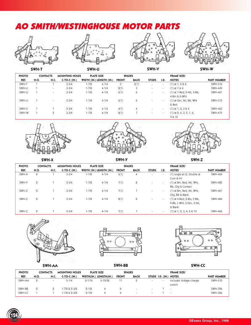
©Essex Group, Inc., 1998124
AO SMITH/WESTINGHOUSE MOTOR PARTS
PHOTO CONTACTS MOUNTING HOLES PLATE SIZE SPADES FRAME SIZE/REF. N.O. N.C. C-TO-C (IN.) WIDTH (IN.) LENGTH (IN.) FRONT BACK STUDS I.D. NOTES PART NUMBER
SWH-T 1 1 3-3/4 1-7/8 4-1/4 3 3(1) - - (1) at 1, 2 & 6 SWH-516
SWH-U 1 - 3-3/4 1-7/8 4-1/4 2(1) 3 - - (1) at 1 & 4 SWH-449
SWH-U 1 - 3-3/4 1-7/8 4-1/4 5(1) 6 - - (1) at 1-Red, 2-Yel, 3-Blk, SWH-461
4-Brn & 6-Wht
SWH-U 1 - 3-3/4 1-7/8 4-1/4 5(1) 6 - - (1) at Grn, Yel, Blk, Wht SWH-515
& Red
SWH-V 1 1 3-3/4 1-7/8 4-1/4 4(1) 4 - - (1) at 1, 2, 3 & 4 SWH-463
SWH-W 1 2 3-3/4 1-7/8 4-1/4 8(1) 7 - - (1) at 2, 4, 3, 5, 1, 6, SWH-479
9 & 10
PHOTO CONTACTS MOUNTING HOLES PLATE SIZE SPADES FRAME SIZE/REF. N.O. N.C. C-TO-C (IN.) WIDTH (IN.) LENGTH (IN.) FRONT BACK STUDS I.D. NOTES PART NUMBER
SWH-X 2 1 3-3/4 1-7/8 4-1/4 5(1) 4 - - (1) single at L0, Double at SWH-469
Com & H1
SWH-Y 2 1 3-3/4 1-7/8 4-1/4 7(1) 8 - - (1) at Brn, Red, Yel, Wht, SWH-485
Blk, Org & Contact
SWH-Z 2 1 3-3/4 1-7/8 4-1/4 7(1) 7 - - (1) at Brn, Red, Yel, Wht, SWH-467
Org, Blk & Blank
SWH-Z 2 1 3-3/4 1-7/8 4-1/4 8(1) 8 - - (1) at 4-Red, 2-Blu, P-Blk, SWH-484
P-Blk, L-Wht, 5-Grn, 3-Yel,
& Blank
SWH-Z 2 1 3-3/4 1-7/8 4-1/4 7(1) 7 - - (1) at 1, 2, 3, 4, 6 & 10 SWH-466
PHOTO CONTACTS MOUNTING HOLES PLATE SIZE SPADES FRAME SIZE/REF. N.O. N.C. C-TO-C (IN.) WIDTH(IN.) LENGTH(IN.) FRONT BACK STUDS I.D. (IN.) NOTES PART NUMBER
SWH-AA 2 - 5-1/4 2-1/16 5-19/32 11 2 - - Includes Voltage change SWH-510
switch
SWH-BB 2 2 1-7/8 & 2-3/8 2-1/8 4 6 - - 1 - SWH-396
SWH-CC 1 1 1-7/8 & 2-3/8 2-1/8 4 4 - - 1 - SWH-366
SWH-T SWH-U SWH-V SWH-W
SWH-X SWH-Y SWH-Z
SWH-AA SWH-BB SWH-CC
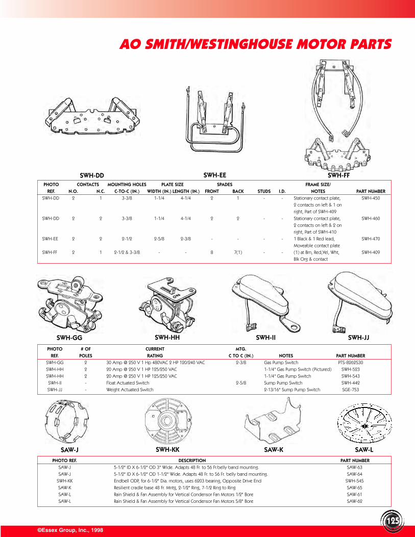
125©Essex Group, Inc., 1998
AO SMITH/WESTINGHOUSE MOTOR PARTS
PHOTO # OF CURRENT MTG.REF. POLES RATING C TO C (IN.) NOTES PART NUMBER
SWH-GG 2 30 Amp @ 250 V 1 Hp 480VAC 2 HP 120/240 VAC 2-3/8 Gas Pump Switch PTS-8262S30
SWH-HH 2 20 Amp @ 250 V 1 HP 125/250 VAC 1-1/4" Gas Pump Switch (Pictured) SWH-523
SWH-HH 2 20 Amp @ 250 V 1 HP 125/250 VAC 1-1/4" Gas Pump Switch SWH-543
SWH-II - Float Actuated Switch 2-5/8 Sump Pump Switch SWH-442
SWH-JJ - Weight Actuated Switch 2-13/16" Sump Pump Switch SGE-753
PHOTO REF. DESCRIPTION PART NUMBERSAW-J 5-1/2" ID X 6-1/2" OD 3" Wide. Adapts 48 Fr. to 56 Fr.belly band mounting. SAW-63
SAW-J 5-1/2" ID X 6-1/2" OD 1-1/2" Wide. Adapts 48 Fr. to 56 Fr. belly band mounting. SAW-64
SWH-KK Endbell ODP, for 6-1/2" Dia. motors, uses 6203 bearing, Opposite Drive End SWH-545
SAW-K Resilient cradle base 48 Fr. Mntg, 2-1/2" Ring, 7-1/2 Ring to Ring SAW-65
SAW-L Rain Shield & Fan Assembly for Vertical Condensor Fan Motors 1/2" Bore SAW-61
SAW-L Rain Shield & Fan Assembly for Vertical Condensor Fan Motors 5/8" Bore SAW-62
PHOTO CONTACTS MOUNTING HOLES PLATE SIZE SPADES FRAME SIZE/REF. N.O. N.C. C-TO-C (IN.) WIDTH (IN.) LENGTH (IN.) FRONT BACK STUDS I.D. NOTES PART NUMBER
SWH-DD 2 1 3-3/8 1-1/4 4-1/4 2 1 - - Stationary contact plate, SWH-450
2 contacts on left & 1 on
right, Part of SWH-409
SWH-DD 2 2 3-3/8 1-1/4 4-1/4 2 2 - - Stationary contact plate, SWH-460
2 contacts on left & 2 on
right, Part of SWH-410
SWH-EE 2 2 2-1/2 2-5/8 2-3/8 - - - - 1 Black & 1 Red lead, SWH-470
Moveable contact plate
SWH-FF 2 1 2-1/2 & 3-3/8 - - 8 7(1) - - (1) at Brn, Red,Yel, Wht, SWH-409
Blk Org & contact
SWH-DD SWH-EE SWH-FF
SWH-GG SWH-HH SWH-II SWH-JJ
SAW-J SWH-KK SAW-K SAW-L
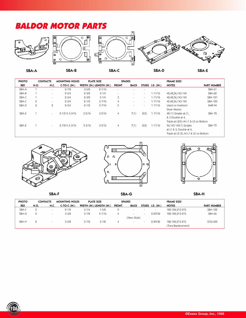
©Essex Group, Inc., 1998126
PHOTO CONTACTS MOUNTING HOLES PLATE SIZE SPADES FRAME SIZE/REF. N.O. N.C. C-TO-C (IN.) WIDTH (IN.) LENGTH (IN.) FRONT BACK STUDS I.D. (IN.) NOTES PART NUMBER
SBA-F 2 - 2-1/2 3-1/4 1-5/8 2 - - - 182-184,213-215 SBA-122
SBA-G 2 - 3-3/8 3-7/8 4-1/16 4 - - 2-29/32 182-184,213-215 SBA-66
(New Style)
SBA-H 2 - 3-3/8 3-7/8 3-7/8 4 - - 2-29/32 182-184,213-215 STQ-400
(Torq Replacement)
PHOTO CONTACTS MOUNTING HOLES PLATE SIZE SPADES FRAME SIZE/REF. N.O. N.C. C-TO-C (IN.) WIDTH (IN.) LENGTH (IN.) FRONT BACK STUDS I.D. (IN.) NOTES PART NUMBER
SBA-A 1 - 2-7/8 3-5/8 2-1/16 - - - - SBA-61
SBA-B 1 - 2-3/4 2-3/8 3-1/4 - - - 1-11/16 42,48,56,143-145 SBA-62
SBA-C 1 - 2-3/4 2-3/8 3-1/4 3 - - 1-11/16 42,48,56,143-145 SBA-121
SBA-C 2 - 2-3/4 2-1/2 3-7/16 4 - - 1-11/16 42,48,56,143-145 SBA-120
SBA-D 2 2 2-3/4 2-1/2 3-7/16 5 - - 1-11/16 Used on Huebsch SMR-94
Dryer Motors
SBA-E 1 - 2-1/2 X 3-3/16 3-5/16 3-5/16 4 7(1) 2(2) 1-11/16 48 (1) Singles at L1, SBA-78
& 3 Double at 4,
Triple at L2(2) At L1 & L2 on Bottom
SBA-E 1 - 2-7/8 X 3-3/16 3-3/16 3-5/16 4 7(1) 2(2) 1-11/16 56,143-145(1) Singles SBA-79
at L1 & 3, Double at 4,
Triple at L2 (2) At L1 & L2 on Bottom
BALDOR MOTOR PARTS
SBA-A SBA-B SBA-C SBA-ESBA-D
SBA-F SBA-G SBA-H
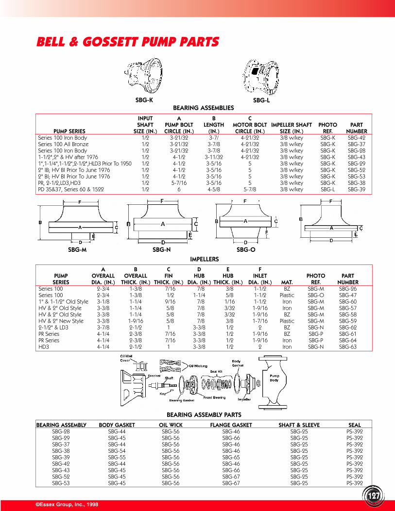
©Essex Group, Inc., 1998
BEARING ASSEMBLY BODY GASKET OIL WICK FLANGE GASKET SHAFT & SLEEVE SEALSBG-28 SBG-44 SBG-56 SBG-46 SBG-25 PS-392SBG-29 SBG-45 SBG-56 SBG-66 SBG-25 PS-392SBG-37 SBG-44 SBG-56 SBG-46 SBG-25 PS-392SBG-38 SBG-54 SBG-56 SBG-46 SBG-25 PS-392SBG-39 SBG-55 SBG-56 SBG-65 SBG-25 PS-392SBG-42 SBG-44 SBG-56 SBG-46 SBG-25 PS-392SBG-43 SBG-45 SBG-56 SBG-66 SBG-25 PS-392SBG-52 SBG-45 SBG-56 SBG-67 SBG-25 PS-392SBG-53 SBG-45 SBG-56 SBG-67 SBG-25 PS-392
BELL & GOSSETT PUMP PARTS
A B C D E FPUMP OVERALL OVERALL FIN HUB HUB INLET PHOTO PARTSERIES DIA. (IN.) THICK. (IN.) THICK. (IN.) DIA. (IN.) THICK. (IN.) DIA. (IN.) MAT. REF. NUMBER
Series 100 2-3/4 1-3/8 7/16 7/8 3/8 1-1/2 BZ SBG-M SBG-26Series 100 2-3/4 1-3/8 1/2 1-1/4 5/8 1-1/2 Plastic SBG-O SBG-471" & 1-1/2" Old Style 3-1/8 1-1/4 9/16 7/8 1/16 1-1/2 Iron SBG-M SBG-60HV & 2" Old Style 3-3/8 1-1/4 5/8 7/8 3/32 1-9/16 Iron SBG-M SBG-57HV & 2" Old Style 3-3/8 1-1/4 5/8 7/8 3/32 1-9/16 BZ SBG-M SBG-58HV & 2" New Style 3-3/8 1-9/16 5/8 7/8 3/8 1-7/16 Plastic SBG-M SBG-592-1/2" & LD3 3-7/8 2-1/2 1 3-3/8 1/2 2 BZ SBG-N SBG-62PR Series 4-1/4 2-3/8 7/16 3-3/8 1/2 1-9/16 BZ SBG-P SBG-61PR Series 4-1/4 2-3/8 7/16 3-3/8 1/2 1-9/16 Iron SBG-P SBG-64HD3 4-1/4 2-1/2 1 3-3/8 1/2 2 Iron SBG-N SBG-63
SBG-K SBG-LBEARING ASSEMBLIES
INPUT A B CSHAFT PUMP BOLT LENGTH MOTOR BOLT IMPELLER SHAFT PHOTO PART
PUMP SERIES SIZE (IN.) CIRCLE (IN.) (IN.) CIRCLE (IN.) SIZE (IN.) REF. NUMBERSeries 100 Iron Body 1/2 3-21/32 3-7/ 4-21/32 3/8 w/key SBG-K SBG-42Series 100 All Bronze 1/2 3-21/32 3-7/8 4-21/32 3/8 w/key SBG-K SBG-37Series 100 Iron Body 1/2 3-21/32 3-7/8 4-21/32 3/8 w/key SBG-K SBG-281-1/2",2" & HV after 1976 1/2 4-1/2 3-11/32 4-21/32 3/8 w/key SBG-K SBG-431",1-1/4",1-1/2",2-1/2",HLD3 Prior To 1950 1/2 4-1/2 3-5/16 5 3/8 w/key SBG-K SBG-292" IB; HV BI Prior To June 1976 1/2 4-1/2 3-5/16 5 3/8 w/key SBG-K SBG-522" BI; HV BI Prior To June 1976 1/2 4-1/2 3-5/16 5 3/8 w/key SBG-K SBG-53PR, 2-1/2,LD3,HD3 1/2 5-7/16 3-5/16 5 3/8 w/key SBG-K SBG-38PD 35&37, Series 60 & 1522 1/2 6 4-5/8 5-7/8 3/8 w/key SBG-L SBG-39
SBG-M SBG-N SBG-O
IMPELLERS
BEARING ASSEMBLY PARTS
127
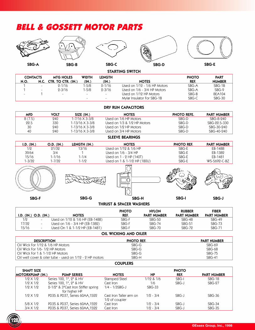
©Essex Group, Inc., 1998128
BELL & GOSSETT MOTOR PARTS
STARTING SWITCHCONTACTS MTG HOLES WIDTH LENGTH PHOTO PART
N.O. N.C. CTR. TO CTR. (IN.) (IN.) (IN.) NOTES REF. NUMBER1 - 2-1/16 1-5/8 2-1/16 Used on 1/12 - 1/6 HP Motors SBG-A SBG-1B1 - 2-3/16 1-5/8 2-3/16 Used on 1/6 - 3/4 HP Motors SBG-A SBG-9- 1 - - - Used on 1/12 HP Motors SBG-B 8EA104
- - Mylar Insulator For SBG-1B SBG-C SBG-30
MFD VOLT SIZE (IN.) NOTES PHOTO REFE. PART NUMBER8 (7.5) 240 1-7/16 X 3-3/8 Used on 1/6 HP Motors SBG-D SBG-8-24022.5 330 1-13/16 X 3-3/8 Used on 1/3 & 1/2 HP Motors SBG-D SBG-22.5-33030 240 1-13/16 X 3-3/8 Used on 1/2 HP Motors SBG-D SBG-30-24040 240 1-13/16 X 3-3/8 Used on 3/4 HP Motors SBG-D SBG-40-240
I.D. (IN.) O.D. (IN.) LENGTH (IN.) NOTES PHOTO REF. PART NUMBER1/2 21/32 13/16 Used on 1/12 & 1/6 HP SBG-E EB-1488
39/64 3/4 1 Used on 1/6 - 3/4 HP SBG-E EB-138215/16 1-1/16 1-1/4 Used on 1 - 2 HP (140T) SBG-E EB-14811-3/32 1-7/32 1-1/2 Used on 1 & 1-1/2 HP (180U) SBG-E WS-5692-C-BZ
SHAFT SIZE PHOTOMOTORXPUMP (IN.) PUMP SERIES NOTES HP REF. PART NUMBER
1/2 X 1/2 Series 100, 1", 2" & HV Stamped Steel 1/12 & 1/6 SBG-I SBG-181/2 X 1/2 Series 100, 1", 2" & HV Cast Iron 1/6 SBG-J SBG-271/2 X 1/2 2-1/2" & 3"Cast Iron Stiffer spring 1/4 - 1/3SBG-J SBG-33
for higher HP1/2 X 1/2 PD35 & PD37, Series 60AA,1522 Cast Iron Taller arm on 1/2 - 3/4 SBG-J SBG-36
1/2 of coupler5/8 X 1/2 PD35 & PD37, Series 60AA,1522 Cast Iron 1/2 - 3/4 SBG-J SBG-343/4 X 1/2 PD35 & PD37, Series 60AA,1522 Cast Iron 1/2 - 3/4 SBG-J SBG-35
DESCRIPTION PHOTO REF. PART NUMBEROil Wick For 1/12 & 1/6 HP Motors SBG-G SBG-69Oil Wick For 1/6- 1/2 HP Motors SBG-G SBG-68Oil Wick For 1 & 1-1/2 HP Motors SBG-G SBG-75Oil well cover & oiler tube - used on 1/12 - 2 HP motors SBG-H SBG-41
SBG-A SBG-B SBG-C SBG-D SBG-E
DRY RUN CAPACITORS
SLEEVE BEARINGS
SBG-F SBG-G SBG-H SBG-I SBG-J
PHOTO NYLON RUBBER FIBERI.D. (IN.) O.D. (IN.) NOTES REF. PART NUMBER PART NUMBER PART NUMBER
1/2 - Used on 1/12 & 1/6 HP (EB-1488) SBG-F SBG-50 SBG-48 SBG-4917/32 - Used on 1/6 - 3/4 HP (EB-1382) SBG-F SBG-74 SBG-51 SBG-7315/16 - Used On 1 & 1-1/2 HP (EB-1481) SBG-F SBG-70 SBG-72 SBG-71
THRUST & SPACER WASHERS
OIL WICKING AND OILER
COUPLERS
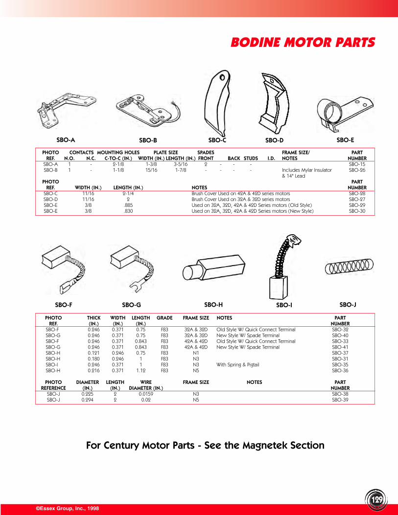
©Essex Group, Inc., 1998129
BODINE MOTOR PARTS
PHOTO CONTACTS MOUNTING HOLES PLATE SIZE SPADES FRAME SIZE/ PARTREF. N.O. N.C. C-TO-C (IN.) WIDTH (IN.) LENGTH (IN.) FRONT BACK STUDS I.D. NOTES NUMBER
SBO-A 1 - 2-1/8 1-3/8 3-5/16 2 - - - SBO-15SBO-B 1 - 1-1/8 15/16 1-7/8 - - - - Includes Mylar Insulator SBO-26
& 14" LeadPHOTO PART
REF. WIDTH (IN.) LENGTH (IN.) NOTES NUMBERSBO-C 11/16 2-1/4 Brush Cover Used on 42A & 42D series motors SBO-28SBO-D 11/16 2 Brush Cover Used on 32A & 32D series motors SBO-27SBO-E 3/8 .885 Used on 32A, 32D, 42A & 42D Series motors (Old Style) SBO-29SBO-E 3/8 .830 Used on 32A, 32D, 42A & 42D Series motors (New Style) SBO-30
PHOTO THICK WIDTH LENGTH GRADE FRAME SIZE NOTES PARTREF. (IN.) (IN.) (IN.) NUMBER
SBO-F 0.246 0.371 0.75 F83 32A & 32D Old Style W/ Quick Connect Terminal SBO-32SBO-G 0.246 0.371 0.75 F83 32A & 32D New Style W/ Spade Terminal SBO-40SBO-F 0.246 0.371 0.843 F83 42A & 42D Old Style W/ Quick Connect Terminal SBO-33SBO-G 0.246 0.371 0.843 F83 42A & 42D New Style W/ Spade Terminal SBO-41SBO-H 0.121 0.246 0.75 F83 N1 SBO-37SBO-H 0.180 0.246 1 F83 N3 SBO-31SBO-I 0.246 0.371 1 F83 N3 With Spring & Pigtail SBO-35SBO-H 0.216 0.371 1.12 F83 N5 SBO-36
PHOTO DIAMETER LENGTH WIRE FRAME SIZE NOTES PARTREFERENCE (IN.) (IN.) DIAMETER (IN.) NUMBER
SBO-J 0.225 2 0.0159 N3 SBO-38SBO-J 0.294 2 0.02 N5 SBO-39
For Century Motor Parts - See the Magnetek Section
SBO-A SBO-B SBO-C SBO-D SBO-E
SBO-F SBO-G SBO-H SBO-I SBO-J
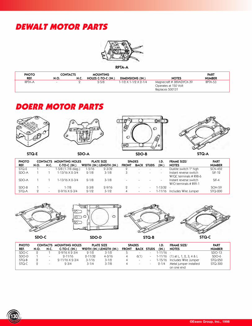
©Essex Group, Inc., 1998130
DEWALT MOTOR PARTS
PHOTO CONTACTS MOUNTING PARTREF. N.O. N.C. HOLES C-TO-C (IN.) DIMENSIONS (IN.) NOTES NUMBER
RPTA-A - 2 2-5/8 1-1/2 X 1-1/2 X 2-1/4 Magnecraft # 389ADYCX-39 RPTA-53Operates at 150 Volt Replaces 500131
PHOTO CONTACTS MOUNTING HOLES PLATE SIZE SPADES I.D. FRAME SIZE/ PARTREF. N.O. N.C. C-TO-C (IN.) WIDTH (IN.) LENGTH (IN.) FRONT BACK STUDS (IN.) NOTES NUMBERSTQ-E 1 - 1-5/8 (1-7/8 diag.) 1-5/16 2-3/32 2 - - - Dustite switch 1" high SCN-452SDO-A 1 1 1-13/16 X 2-3/4 2-1/8 3-1/8 3 - - - Instant reverse switch SIF-12
W/QC terminals # R98-6SDO-A 1 1 1-13/16 X 2-3/4 2-1/8 3-1/8 - - - - Instant reverse switch SIF-4
W/O terminals # R99-1SDO-B 1 - 1-7/8 2-3/8 2-9/16 2 - - 1-13/32 - SOH-59STQ-A 2 - 2-9/16 X 2-3/4 2-1/2 3-1/2 4 - - 1-11/16 Includes Wire Jumper STQ-200
PHOTO CONTACTS MOUNTING HOLES PLATE SIZE SPADES I.D. FRAME SIZE/ PARTREF. N.O. N.C. C-TO-C (IN.) WIDTH (IN.) LENGTH (IN.) FRONT BACK STUDS (IN.) NOTES NUMBERSDO-C 2 1 2-9/16 X 2-3/4 2-1/2 3-1/2 5 - - 1-11/16 - SDO-13SDO-D 1 - 2-11/16 2-11/32 4-3/16 4 6(1) - 1-11/16 (1) at L, 1, 2, 3, 4 & L SDO-6STQ-B 2 - 2-11/16 X 2-3/4 3-1/16 3-1/2 4 - - 1-15/16 Includes Wire Jumper STQ-250STQ-C 2 - 2-3/4 3-1/4 3-7/8 4 - - 2-1/4 Metal jumper installed STQ-300
on one end
DOERR MOTOR PARTS
RPTA-A
STQ-E SDO-A SDO-B STQ-A
SDO-C SDO-D STQ-B STQ-C
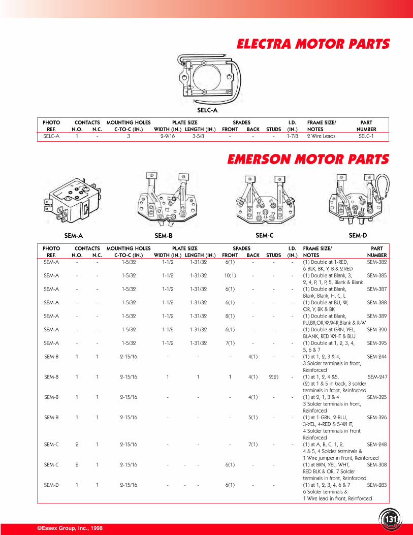
©Essex Group, Inc., 1998131
PHOTO CONTACTS MOUNTING HOLES PLATE SIZE SPADES I.D. FRAME SIZE/ PARTREF. N.O. N.C. C-TO-C (IN.) WIDTH (IN.) LENGTH (IN.) FRONT BACK STUDS (IN.) NOTES NUMBER
SELC-A 1 - 3 2-9/16 3-5/8 - - - 1-7/8 2 Wire Leads SELC-1
PHOTO CONTACTS MOUNTING HOLES PLATE SIZE SPADES I.D. FRAME SIZE/ PARTREF. N.O. N.C. C-TO-C (IN.) WIDTH (IN.) LENGTH (IN.) FRONT BACK STUDS (IN.) NOTES NUMBER
SEM-A - - 1-5/32 1-1/2 1-31/32 6(1) - - - (1) Double at 1-RED, SEM-3826-BLK, BK, Y, B & 2 RED
SEM-A - - 1-5/32 1-1/2 1-31/32 10(1) - - - (1) Double at Blank, 3, SEM-3852, 4, P, 1, P, 5, Blank & Blank
SEM-A - - 1-5/32 1-1/2 1-31/32 6(1) - - - (1) Double at Blank, SEM-387 Blank, Blank, H, C, L
SEM-A - - 1-5/32 1-1/2 1-31/32 6(1) - - - (1) Double at BU, W, SEM-388 OR, Y, BK & BK
SEM-A - - 1-5/32 1-1/2 1-31/32 8(1) - - - (1) Double at Blank, SEM-389 PU,BR,OR,W,W-R,Blank & R-W
SEM-A - - 1-5/32 1-1/2 1-31/32 6(1) - - - (1) Double at GRN, YEL, SEM-390 BLANK, RED WHT & BLU
SEM-A - - 1-5/32 1-1/2 1-31/32 7(1) - - - (1) Double at 1, 2, 3, 4, SEM-3955, 6 & 7
SEM-B 1 1 2-15/16 - - - 4(1) - - (1) at 1, 2, 3 & 4, SEM-2443 Solder terminals in front, Reinforced
SEM-B 1 1 2-15/16 1 1 1 4(1) 2(2) - (1) at 1, 2, 4 &5, SEM-247(2) at 1 & 5 in back, 3 solderterminals in front, Reinforced
SEM-B 1 1 2-15/16 - - - 4(1) - - (1) at 2, 1, 3 & 4 SEM-3253 Solder terminals in front, Reinforced
SEM-B 1 1 2-15/16 - - - 5(1) - - (1) at 1-GRN, 2-BLU, SEM-3263-YEL, 4-RED & 5-WHT,4 Solder terminals in Front Reinforced
SEM-C 2 1 2-15/16 - - - 7(1) - - (1) at A, B, C, 1, 2, SEM-2484 & 5, 4 Solder terminals & 1 Wire jumper in Front, Reinforced
SEM-C 2 1 2-15/16 - - - 6(1) - - (1) at BRN, YEL, WHT, SEM-308RED BLK & OR, 7 Solder terminals in front, Reinforced
SEM-D 1 1 2-15/16 - - - 6(1) - - (1) at 1, 2, 3, 4, 6 & 7 SEM-2836 Solder terminals & 1 Wire lead in front, Reinforced
ELECTRA MOTOR PARTS
EMERSON MOTOR PARTS
SEM-A
SELC-A
SEM-B SEM-C SEM-D
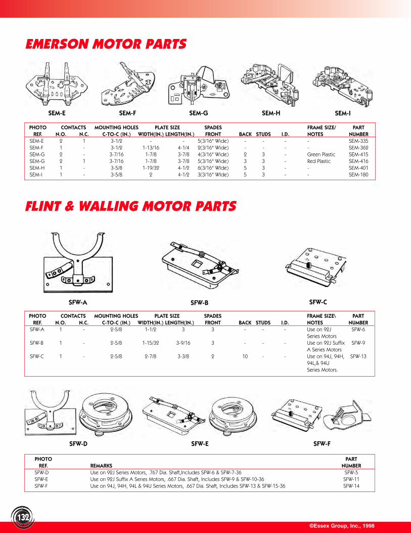
©Essex Group, Inc., 1998132
EMERSON MOTOR PARTS
PHOTO CONTACTS MOUNTING HOLES PLATE SIZE SPADES FRAME SIZE/ PARTREF. N.O. N.C. C-TO-C (IN.) WIDTH(IN.) LENGTH(IN.) FRONT BACK STUDS I.D. NOTES NUMBER
SEM-E 2 1 3-1/2 - - 5(3/16" Wide) - - - - SEM-335SEM-F 1 - 3-1/2 1-13/16 4-1/4 2(3/16" Wide) - - - - SEM-362SEM-G 2 - 3-7/16 1-7/8 3-7/8 4(3/16" Wide) 2 3 - Green Plastic SEM-415SEM-G 2 1 3-7/16 1-7/8 3-7/8 5(3/16" Wide) 3 3 - Red Plastic SEM-416SEM-H 1 - 3-5/8 1-19/32 4-1/2 6(3/16" WIde) 5 3 - - SEM-401SEM-I 1 - 3-5/8 2 4-1/2 3(3/16" WIde) 5 3 - - SEM-180
PHOTO CONTACTS MOUNTING HOLES PLATE SIZE SPADES FRAME SIZE\ PARTREF. N.O. N.C. C-TO-C (IN.) WIDTH(IN.) LENGTH(IN.) FRONT BACK STUDS I.D. NOTES NUMBER
SFW-A 1 - 2-5/8 1-1/2 3 3 - - - Use on 92J SFW-6Series Motors
SFW-B 1 - 2-5/8 1-15/32 3-9/16 3 - - - Use on 92J Suffix SFW-9A Series Motors
SFW-C 1 - 2-5/8 2-7/8 3-3/8 2 10 - - Use on 94J, 94H, SFW-1394L,& 94U Series Motors.
PHOTO PARTREF. REMARKS NUMBER
SFW-D Use on 92J Series Motors, .767 Dia. Shaft,Includes SFW-6 & SFW-7-36 SFW-5SFW-E Use on 92J Suffix A Series Motors, .667 Dia. Shaft, Includes SFW-9 & SFW-10-36 SFW-11SFW-F Use on 94J, 94H, 94L & 94U Series Motors, .667 Dia. Shaft, Includes SFW-13 & SFW-15-36 SFW-14
FLINT & WALLING MOTOR PARTS
SFW-A SFW-B SFW-C
SFW-D SFW-E SFW-F
SEM-E SEM-ISEM-G SEM-HSEM-F
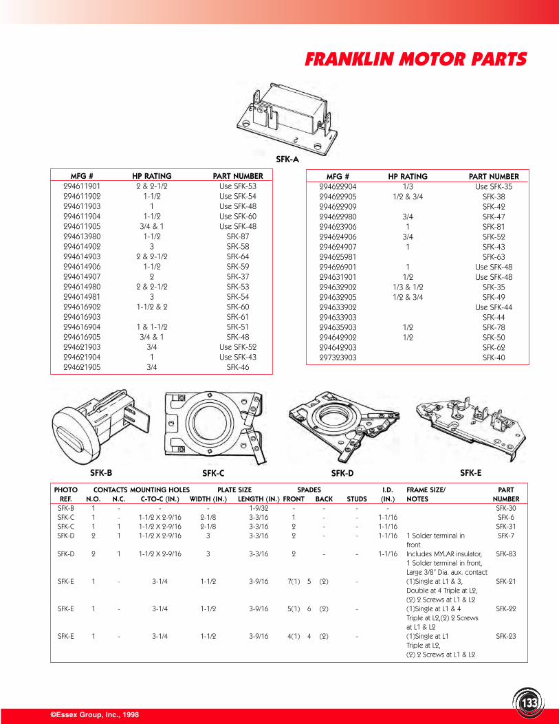
©Essex Group, Inc., 1998
FRANKLIN MOTOR PARTS
133
MFG # HP RATING PART NUMBER294622904 1/3 Use SFK-35294622905 1/2 & 3/4 SFK-38294622909 SFK-42294622980 3/4 SFK-47294623906 1 SFK-81294624906 3/4 SFK-52294624907 1 SFK-43294625981 SFK-63294626901 1 Use SFK-48294631901 1/2 Use SFK-48294632902 1/3 & 1/2 SFK-35294632905 1/2 & 3/4 SFK-49294633902 Use SFK-44294633903 SFK-44294635903 1/2 SFK-78294642902 1/2 SFK-50294642903 SFK-62297323903 SFK-40
PHOTO CONTACTS MOUNTING HOLES PLATE SIZE SPADES I.D. FRAME SIZE/ PARTREF. N.O. N.C. C-TO-C (IN.) WIDTH (IN.) LENGTH (IN.) FRONT BACK STUDS (IN.) NOTES NUMBER
SFK-B 1 - - - 1-9/32 - - - - SFK-30SFK-C 1 - 1-1/2 X 2-9/16 2-1/8 3-3/16 1 - - 1-1/16 SFK-6SFK-C 1 1 1-1/2 X 2-9/16 2-1/8 3-3/16 2 - - 1-1/16 SFK-31SFK-D 2 1 1-1/2 X 2-9/16 3 3-3/16 2 - - 1-1/16 1 Solder terminal in SFK-7
frontSFK-D 2 1 1-1/2 X 2-9/16 3 3-3/16 2 - - 1-1/16 Includes MYLAR insulator, SFK-83
1 Solder terminal in front,Large 3/8” Dia. aux. contact
SFK-E 1 - 3-1/4 1-1/2 3-9/16 7(1) 5 (2) - (1)Single at L1 & 3, SFK-21Double at 4 Triple at L2,(2) 2 Screws at L1 & L2
SFK-E 1 - 3-1/4 1-1/2 3-9/16 5(1) 6 (2) - (1)Single at L1 & 4 SFK-22Triple at L2,(2) 2 Screws at L1 & L2
SFK-E 1 - 3-1/4 1-1/2 3-9/16 4(1) 4 (2) - (1)Single at L1 SFK-23Triple at L2,(2) 2 Screws at L1 & L2
MFG # HP RATING PART NUMBER294611901 2 & 2-1/2 Use SFK-53294611902 1-1/2 Use SFK-54294611903 1 Use SFK-48294611904 1-1/2 Use SFK-60294611905 3/4 & 1 Use SFK-48294613980 1-1/2 SFK-87294614902 3 SFK-58294614903 2 & 2-1/2 SFK-64294614906 1-1/2 SFK-59294614907 2 SFK-37294614980 2 & 2-1/2 SFK-53294614981 3 SFK-54294616902 1-1/2 & 2 SFK-60294616903 SFK-61294616904 1 & 1-1/2 SFK-51294616905 3/4 & 1 SFK-48294621903 3/4 Use SFK-52294621904 1 Use SFK-43294621905 3/4 SFK-46
SFK-A
SFK-B SFK-C SFK-D SFK-E
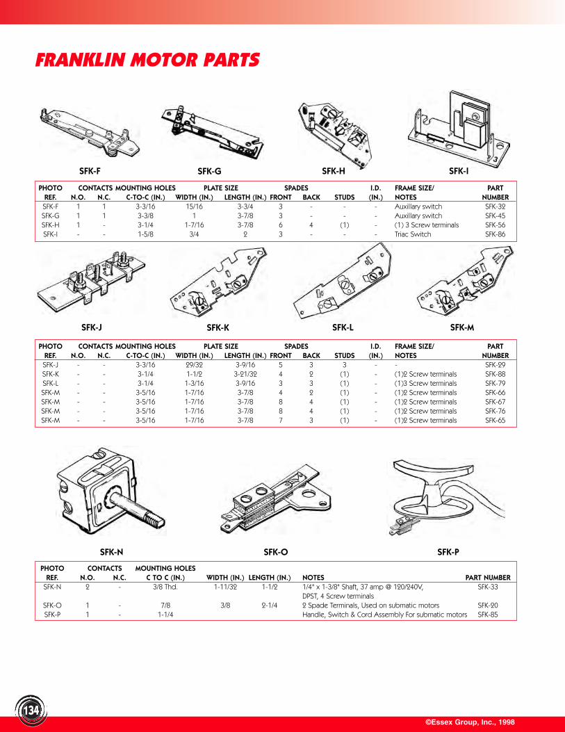
©Essex Group, Inc., 1998
FRANKLIN MOTOR PARTS
134
PHOTO CONTACTS MOUNTING HOLES PLATE SIZE SPADES I.D. FRAME SIZE/ PARTREF. N.O. N.C. C-TO-C (IN.) WIDTH (IN.) LENGTH (IN.) FRONT BACK STUDS (IN.) NOTES NUMBERSFK-F 1 1 3-3/16 15/16 3-3/4 3 - - - Auxillary switch SFK-32SFK-G 1 1 3-3/8 1 3-7/8 3 - - - Auxillary switch SFK-45SFK-H 1 - 3-1/4 1-7/16 3-7/8 6 4 (1) - (1) 3 Screw terminals SFK-56SFK-I - - 1-5/8 3/4 2 3 - - - Triac Switch SFK-86
PHOTO CONTACTS MOUNTING HOLES PLATE SIZE SPADES I.D. FRAME SIZE/ PARTREF. N.O. N.C. C-TO-C (IN.) WIDTH (IN.) LENGTH (IN.) FRONT BACK STUDS (IN.) NOTES NUMBERSFK-J - - 3-3/16 29/32 3-9/16 5 3 3 - - SFK-29SFK-K - - 3-1/4 1-1/2 3-21/32 4 2 (1) - (1)2 Screw terminals SFK-88SFK-L - - 3-1/4 1-3/16 3-9/16 3 3 (1) - (1)3 Screw terminals SFK-79SFK-M - - 3-5/16 1-7/16 3-7/8 4 2 (1) - (1)2 Screw terminals SFK-66SFK-M - - 3-5/16 1-7/16 3-7/8 8 4 (1) - (1)2 Screw terminals SFK-67SFK-M - - 3-5/16 1-7/16 3-7/8 8 4 (1) - (1)2 Screw terminals SFK-76SFK-M - - 3-5/16 1-7/16 3-7/8 7 3 (1) - (1)2 Screw terminals SFK-65
PHOTO CONTACTS MOUNTING HOLESREF. N.O. N.C. C TO C (IN.) WIDTH (IN.) LENGTH (IN.) NOTES PART NUMBER
SFK-N 2 - 3/8 Thd. 1-11/32 1-1/2 1/4" x 1-3/8" Shaft, 37 amp @ 120/240V, SFK-33DPST, 4 Screw terminals
SFK-O 1 - 7/8 3/8 2-1/4 2 Spade Terminals, Used on submatic motors SFK-20SFK-P 1 - 1-1/4 Handle, Switch & Cord Assembly For submatic motors SFK-85
SFK-F SFK-G SFK-H SFK-I
SFK-J SFK-K SFK-L SFK-M
SFK-N SFK-O SFK-P
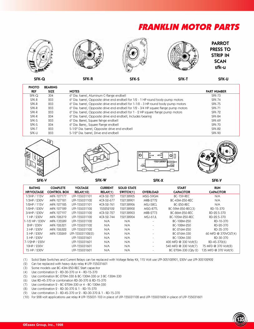
PARROTPRESS TOSTRIP IN
SCANsfk-u
©Essex Group, Inc., 1998
FRANKLIN MOTOR PARTS
135
PHOTO BEARINGREF SIZE NOTES PART NUMBER
SFK-Q 304 6" Dia. barrel, Aluminum C-flange endbell SFK-73SFK-R 203 6" Dia. barrel, Opposite drive end endbell for 1/2 - 1 HP round body pump motors SFK-74SFK-R 203 6" Dia. barrel, Opposite drive end endbell for 1-1/2 - 3 HP round body pump motors SFK-75SFK-R 203 6" Dia. barrel, Opposite drive end endbell for 1/2 - 3/4 HP square flange pump motors SFK-71SFK-R 203 6" Dia. barrel, Opposite drive end endbell for 1 - 2 HP square flange pump motors SFK-72SFK-R 204 6" Dia. barrel, Opposite drive end endbell, Includes bearing SFK-84SFK-S 203 6" Dia. Barrel, Square falnge endbell SFK-69SFK-S 204 6" Dia. Barre;, Square Flange endbell SFK-70SFK-T 203 5-1/2" Dia. barrel, Opposite drive end endbell SFK-82SFK-U 203 5-1/2" Dia. barrel, Drive end endbell SFK-90
RATING COMPLETE VOLTAGE CURRENT SOLID STATE START RUNHP/VOLTAGE CONTROL BOX RELAY(10) RELAY(1) SWITCH(1) OVERLOAD CAPACITOR CAPACITOR1/3HP / 115V MFK-127177 LFP-155031101 4CR-52-727 152138905 MSG-59GM BC-159-REC N/A1/3HP / 230V MFK-127181 LFP-155031102 4CR-52-677 152138901 MRB-2772 BC-43M-250-REC N/A1/2HP / 115V MFK-127185 LFP-155031101 4CR-52-761 152138906 MSJ-58CL BC-250-REC N/A1/2HP / 230V MFK-127189 LFP-155031102 155252102 152138902 MSG-87TL BC-59M-250-REC(3) RD-15-3703/4HP / 230V MFK-127197 LFP-155031102 4CR-52-727 152138903 MRB-2773 BC-86M-250-REC RD-22.5-3701 HP / 230V MFK-126319 LFP-155031102 4CR-52-744 152138904 MSJ-61JL BC-105M-250-REC RD-22.5-370
1-1/2 HP / 230V MFK-135589 LFP-155031102 N/A N/A - BC-108M-250 RD-10-3702HP / 230V MFK-126321 LFP-155031102 N/A N/A - BC-108M-250 RD-20-3703 HP / 230V MFK-126322 LFP-155031102 N/A N/A - BC-216M-250 RD-35-3705 HP / 230V MFK-135269 LFP-155031102(2) N/A N/A - BC-216M-330 60 MFD @ 370VOLT(4)5 HP / 230V LFP-155031601 N/A N/A - BC-130M-330 RD-30-370
7-1/2HP / 230V LFP-155031601 N/A N/A - 400 MFD @ 330 Volt(5) RD-45-370(6)10HP / 230V LFP-155031601 N/A N/A - 540 MFD @ 330 Volt(7) 75 MFD @ 370 Volt(8)15 HP / 230V LFP-155031601 N/A N/A - BC-270M-330 (Qty 2) 135 MFD @ 370 Volt(9)
(1) Solid State Switches and Current Relays can be replaced with Voltage Relay Kit, 115 Volt use LFP-305102901, 230V use LFP-305102902(2) Can be replaced with heavy duty relay # LFP-155031601(3) Some models use BC-43M-250-REC Start capacitor(4) Use combination 2 - RD-30-370 or 4 - RD-15-370(5) Use combination BC-270M-330 & BC-130M-330 or 3 BC-130M-330(6) Use RD-45-370 or combination RD-30-370 & RD-15-370(7) Use combination 2 - BC-270M-330 or 4 - BC-130M-330(8) Use combination 2 - RD-30-370 & 1 - RD-15-370(9) Use combination 3 - RD-45-370 or 2 - RD-30-370 & 1 - RD-15-370(10) For 208 volt applications use relay # LFP-155031-103 in place of LFP-155031102 and LFP-155031602 in place of LFP-155031601
SFK-Q SFK-R SFK-S SFK-T SFK-U
SFK-V SFK-W SFK-X SFK-Y
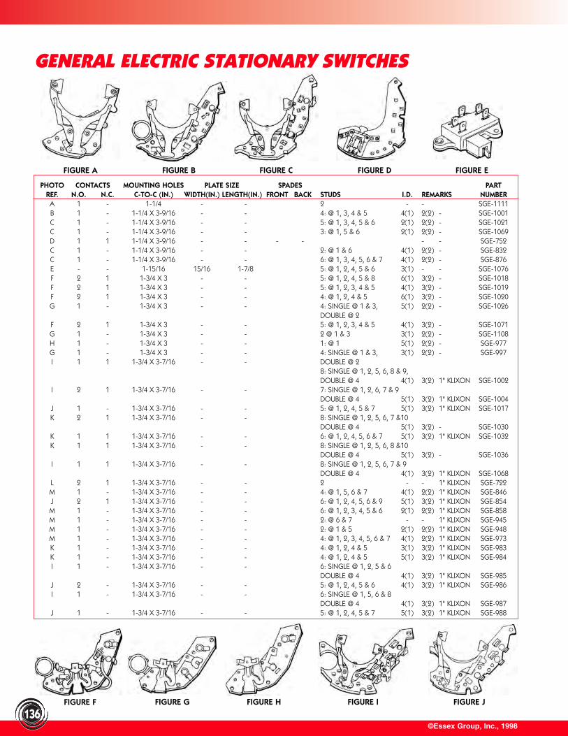
FIGURE F FIGURE G FIGURE H
©Essex Group, Inc., 1998136
PHOTO CONTACTS MOUNTING HOLES PLATE SIZE SPADES PARTREF. N.O. N.C. C-TO-C (IN.) WIDTH(IN.) LENGTH(IN.) FRONT BACK STUDS I.D. REMARKS NUMBERA 1 - 1-1/4 - - 2 - - SGE-1111B 1 - 1-1/4 X 3-9/16 - - 4: @ 1, 3, 4 & 5 4(1) 2(2) - SGE-1001C 1 - 1-1/4 X 3-9/16 - - 5: @ 1, 3, 4, 5 & 6 2(1) 2(2) - SGE-1021C 1 - 1-1/4 X 3-9/16 - - 3: @ 1, 5 & 6 2(1) 2(2) - SGE-1069D 1 1 1-1/4 X 3-9/16 - - - - - - SGE-752C 1 - 1-1/4 X 3-9/16 - - 2: @ 1 & 6 4(1) 2(2) - SGE-832C 1 - 1-1/4 X 3-9/16 - - 6: @ 1, 3, 4, 5, 6 & 7 4(1) 2(2) - SGE-876E - - 1-15/16 15/16 1-7/8 5: @ 1, 2, 4, 5 & 6 3(1) - - SGE-1076F 2 1 1-3/4 X 3 - - 5: @ 1, 2, 4, 5 & 8 6(1) 3(2) - SGE-1018F 2 1 1-3/4 X 3 - - 5: @ 1, 2, 3, 4 & 5 4(1) 3(2) - SGE-1019F 2 1 1-3/4 X 3 - - 4: @ 1, 2, 4 & 5 6(1) 3(2) - SGE-1020G 1 - 1-3/4 X 3 - - 4: SINGLE @ 1 & 3, 5(1) 2(2) - SGE-1026
DOUBLE @ 2F 2 1 1-3/4 X 3 - - 5: @ 1, 2, 3, 4 & 5 4(1) 3(2) - SGE-1071G 1 - 1-3/4 X 3 - - 2 @ 1 & 3 3(1) 2(2) - SGE-1108H 1 - 1-3/4 X 3 - - 1: @ 1 5(1) 2(2) - SGE-977G 1 - 1-3/4 X 3 - - 4: SINGLE @ 1 & 3, 3(1) 2(2) - SGE-997I 1 1 1-3/4 X 3-7/16 - - DOUBLE @ 2
8: SINGLE @ 1, 2, 5, 6, 8 & 9,DOUBLE @ 4 4(1) 3(2) 1" KLIXON SGE-1002
I 2 1 1-3/4 X 3-7/16 - - 7: SINGLE @ 1, 2, 6, 7 & 9DOUBLE @ 4 5(1) 3(2) 1" KLIXON SGE-1004
J 1 - 1-3/4 X 3-7/16 - - 5: @ 1, 2, 4, 5 & 7 5(1) 3(2) 1" KLIXON SGE-1017K 2 1 1-3/4 X 3-7/16 - - 8: SINGLE @ 1, 2, 5, 6, 7 &10
DOUBLE @ 4 5(1) 3(2) - SGE-1030K 1 1 1-3/4 X 3-7/16 - - 6: @ 1, 2, 4, 5, 6 & 7 5(1) 3(2) 1" KLIXON SGE-1032K 1 1 1-3/4 X 3-7/16 - - 8: SINGLE @ 1, 2, 5, 6, 8 &10
DOUBLE @ 4 5(1) 3(2) - SGE-1036I 1 1 1-3/4 X 3-7/16 - - 8: SINGLE @ 1, 2, 5, 6, 7 & 9
DOUBLE @ 4 4(1) 3(2) 1" KLIXON SGE-1068L 2 1 1-3/4 X 3-7/16 - - 2 - - 1" KLIXON SGE-722M 1 - 1-3/4 X 3-7/16 - - 4: @ 1, 5, 6 & 7 4(1) 2(2) 1" KLIXON SGE-846J 2 1 1-3/4 X 3-7/16 - - 6: @ 1, 2, 4, 5, 6 & 9 5(1) 3(2) 1" KLIXON SGE-854M 1 - 1-3/4 X 3-7/16 - - 6: @ 1, 2, 3, 4, 5 & 6 2(1) 2(2) 1" KLIXON SGE-858M 1 - 1-3/4 X 3-7/16 - - 2: @ 6 & 7 - - 1" KLIXON SGE-945M 1 - 1-3/4 X 3-7/16 - - 2: @ 1 & 5 2(1) 2(2) 1" KLIXON SGE-948M 1 - 1-3/4 X 3-7/16 - - 4: @ 1, 2, 3, 4, 5, 6 & 7 4(1) 2(2) 1" KLIXON SGE-973K 1 - 1-3/4 X 3-7/16 - - 4: @ 1, 2, 4 & 5 3(1) 3(2) 1" KLIXON SGE-983K 1 - 1-3/4 X 3-7/16 - - 4: @ 1, 2, 4 & 5 5(1) 3(2) 1" KLIXON SGE-984I 1 - 1-3/4 X 3-7/16 - - 6: SINGLE @ 1, 2, 5 & 6
DOUBLE @ 4 4(1) 3(2) 1" KLIXON SGE-985J 2 - 1-3/4 X 3-7/16 - - 5: @ 1, 2, 4, 5 & 6 4(1) 3(2) 1" KLIXON SGE-986I 1 - 1-3/4 X 3-7/16 - - 6: SINGLE @ 1, 5, 6 & 8
DOUBLE @ 4 4(1) 3(2) 1" KLIXON SGE-987J 1 - 1-3/4 X 3-7/16 - - 5: @ 1, 2, 4, 5 & 7 5(1) 3(2) 1" KLIXON SGE-988
FIGURE A FIGURE B FIGURE C FIGURE D FIGURE E
GENERAL ELECTRIC STATIONARY SWITCHES
FIGURE I FIGURE J
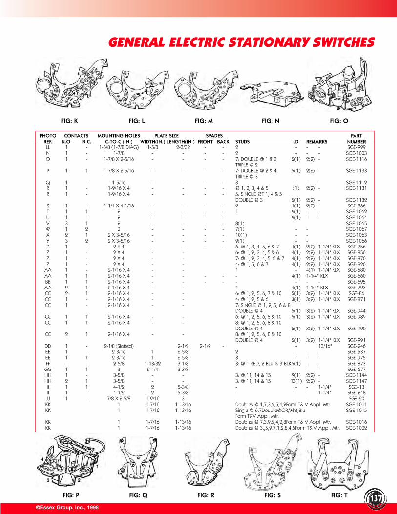
FIG: P FIG: Q FIG: R FIG: S FIG: T
FIG: K FIG: L FIG: M FIG: N FIG: O
PHOTO CONTACTS MOUNTING HOLES PLATE SIZE SPADES PARTREF. N.O. N.C. C-TO-C (IN.) WIDTH(IN.) LENGTH(IN.) FRONT BACK STUDS I.D. REMARKS NUMBERLL 1 - 1-5/8 (1-7/8 DIAG) 1-5/8 2-3/32 - - 2 - - - SGE-999N 1 - 1-7/8 - - - - 2 - - - SGE-1003O 1 - 1-7/8 X 2-5/16 - - - - 7: DOUBLE @ 1 & 3 5(1) 2(2) - SGE-1116
TRIPLE @ 2P 1 1 1-7/8 X 2-5/16 - - - - 7: DOUBLE @ 2 & 4, 5(1) 2(2) - SGE-1133
TRIPLE @ 3Q 1 - 1-5/16 - - - - 3 - - - SGE-1112R 1 - 1-9/16 X 4 - - - - @ 1, 2, 3, 4 & 5 (1) 2(2) - SGE-1131R 1 - 1-9/16 X 4 - - - - 5: SINGLE @T 1, 4 & 5
DOUBLE @ 3 5(1) 2(2) - SGE-1132S 1 - 1-1/4 X 4-1/16 - - - - 2 4(1) 2(2) - SGE-866T 1 1 2 - - - - 1 9(1) - - SGE-1062U 1 - 2 - - - - 9(1) - - SGE-1064V 3 1 2 - - - - 8(1) SGE-1065W 1 2 2 - - - - 7(1) - - SGE-1067X 2 1 2 X 3-5/16 - - - - 10(1) - - SGE-1063Y 3 2 2 X 3-5/16 - - - - 9(1) - - SGE-1066Z 1 - 2 X 4 - - - - 6: @ 1, 3, 4, 5, 6 & 7 4(1) 2(2) 1-1/4" KLX SGE-756Z 1 - 2 X 4 - - 6: @ 1, 2, 3, 4, 5 & 6 4(1) 2(2) 1-1/4" KLX SGE-856Z 1 - 2 X 4 - - 7: @ 1, 2, 3, 4, 5, 6 & 7 4(1) 2(2) 1-1/4" KLX SGE-870Z 1 - 2 X 4 - - 4: @ 1, 5, 6 & 7 4(1) 2(2) 1-1/4" KLX SGE-920
AA 1 - 2-1/16 X 4 - - 1 - 4(1) 1-1/4" KLX SGE-580AA 1 1 2-1/16 X 4 - - - - - 4(1) 1-1/4" KLX SGE-660BB 1 1 2-1/16 X 4 - - - - - - - - SGE-695AA 2 1 2-1/16 X 4 - - - 1 4(1) 1-1/4" KLX SGE-723CC 2 1 2-1/16 X 4 - - 6: @ 1, 2, 5, 6, 7 & 10 5(1) 3(2) 1-1/4" KLX SGE-86CC 1 - 2-1/16 X 4 - - 4: @ 1, 2, 5 & 6 3(1) 3(2) 1-1/4" KLX SGE-871CC 1 - 2-1/16 X 4 - - 7: SINGLE @ 1, 2, 5, 6 & 8
DOUBLE @ 4 5(1) 3(2) 1-1/4" KLX SGE-944CC 1 1 2-1/16 X 4 - - 6: @ 1, 2, 5, 6, 8 & 10 5(1) 3(2) 1-1/4" KLX SGE-989CC 1 1 2-1/16 X 4 - - 8: @ 1, 2, 5, 6, 8 & 10
DOUBLE @ 4 5(1) 3(2) 1-1/4" KLX SGE-990CC 2 1 2-1/16 X 4 - - 8: @ 1, 2, 5, 6, 8 & 10
DOUBLE @ 4 5(1) 3(2) 1-1/4" KLX SGE-991DD 1 - 2-1/8 (Slotted) 2-1/2 2-1/2 - - 13/16" SGE-246EE 1 - 2-3/16 1 2-5/8 2 - - - SGE-537EE 1 1 2-3/16 1 2-5/8 3 - - - SGE-975FF - - 2-5/8 1-13/32 3-1/8 3: @ 1-RED, 2-BLU & 3-BLK 5(1) - - SGE-873
GG 1 1 3 2-1/4 3-3/8 - - - - SGE-677HH 1 - 3-5/8 - - 3: @ 11, 14 & 15 9(1) 2(2) - SGE-1144HH 2 1 3-5/8 - - 3: @ 11, 14 & 15 13(1) 2(2) - SGE-1147II 1 1 4-1/2 2 5-3/8 - - - 1-1/4" SGE-13II 1 - 4-1/2 2 5-3/8 - - - 1-1/4" SGE-248JJ 1 - 7/8 X 2-5/8 1-9/16 3 - - - - SGE-20KK 1 1-7/16 1-13/16 Doubles @ 1,7,3,6,5,4,2Form T& V Appl. Mtr. SGE-1011KK 1 1-7/16 1-13/16 Single @ 6,7Double@OR,Wht,Blu SGE-1015
Form T&V Appl. Mtr.KK 1 1-7/16 1-13/16 Doubles @ 7,3,9,5,4,2,8Form T& V Appl. Mtr. SGE-1016KK 1 1-7/16 1-13/16 Doubles @ 3,,5,9,7,1,2,8,4,6Form T& V Appl. Mtr. SGE-1022
137©Essex Group, Inc., 1998
GENERAL ELECTRIC STATIONARY SWITCHES
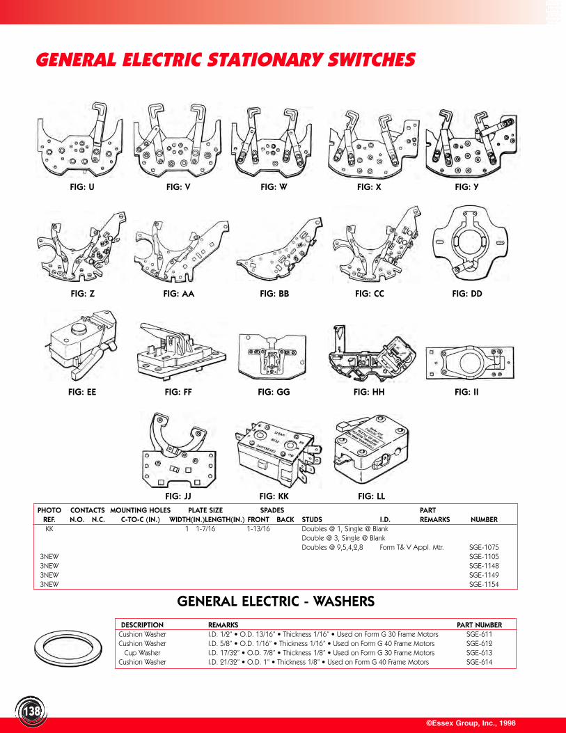
FIG: U FIG: V FIG: W FIG: X FIG: Y
FIG: Z FIG: AA FIG: BB FIG: CC FIG: DD
FIG: EE FIG: FF FIG: GG FIG: HH FIG: II
©Essex Group, Inc., 1998138
GENERAL ELECTRIC STATIONARY SWITCHES
GENERAL ELECTRIC - WASHERSDESCRIPTION REMARKS PART NUMBER
Cushion Washer I.D. 1/2” • O.D. 13/16” • Thickness 1/16” • Used on Form G 30 Frame Motors SGE-611Cushion Washer I.D. 5/8” • O.D. 1/16” • Thickness 1/16” • Used on Form G 40 Frame Motors SGE-612
Cup Washer I.D. 17/32” • O.D. 7/8” • Thickness 1/8” • Used on Form G 30 Frame Motors SGE-613Cushion Washer I.D. 21/32” • O.D. 1” • Thickness 1/8” • Used on Form G 40 Frame Motors SGE-614
FIG: JJ FIG: KK FIG: LL
PHOTO CONTACTS MOUNTING HOLES PLATE SIZE SPADES PARTREF. N.O. N.C. C-TO-C (IN.) WIDTH(IN.)LENGTH(IN.) FRONT BACK STUDS I.D. REMARKS NUMBERKK 1 1-7/16 1-13/16 Doubles @ 1, Single @ Blank
Double @ 3, Single @ BlankDoubles @ 9,5,4,2,8 Form T& V Appl. Mtr. SGE-1075
3NEW SGE-11053NEW SGE-11483NEW SGE-11493NEW SGE-1154
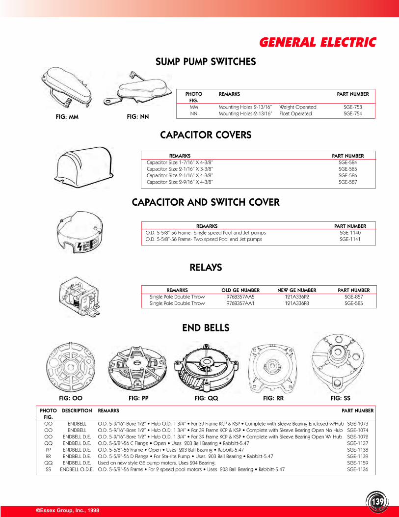
©Essex Group, Inc., 1998
GENERAL ELECTRIC
139
PHOTO REMARKS PART NUMBERFIG.MM Mounting Holes 2-13/16” Weight Operated SGE-753NN Mounting Holes-2-13/16” Float Operated SGE-754
RELAYS
CAPACITOR AND SWITCH COVER
REMARKS PART NUMBERCapacitor Size 1-7/16” X 4-3/8” SGE-584 Capacitor Size 2-1/16” X 3-3/8” SGE-585Capacitor Size 2-1/16” X 4-3/8” SGE-586 Capacitor Size 2-9/16” X 4-3/8” SGE-587
REMARKS PART NUMBERO.D. 5-5/8”-56 Frame- Single speed Pool and Jet pumps SGE-1140 O.D. 5-5/8”-56 Frame- Two speed Pool and Jet pumps SGE-1141
REMARKS OLD GE NUMBER NEW GE NUMBER PART NUMBERSingle Pole Double Throw 976B357AA5 121A336P2 SGE-857 Single Pole Double Throw 976B357AA1 121A336P8 SGE-585
SUMP PUMP SWITCHES
FIG: MM FIG: NN
CAPACITOR COVERS
FIG: OO FIG: PP FIG: QQ FIG: RR FIG: SS
END BELLS
PHOTO DESCRIPTION REMARKS PART NUMBERFIG.OO ENDBELL O.D. 5-9/16”-Bore 1/2” • Hub O.D. 1 3/4” • For 39 Frame KCP & KSP • Complete with Sleeve Bearing Enclosed w/Hub SGE-1073OO ENDBELL O.D. 5-9/16”-Bore 1/2” • Hub O.D. 1 3/4” • For 39 Frame KCP & KSP • Complete with Sleeve Bearing Open No Hub SGE-1074OO ENDBELL D.E. O.D. 5-9/16”-Bore 1/2” • Hub O.D. 1 3/4” • For 39 Frame KCP & KSP • Complete with Sleeve Bearing Open W/ Hub SGE-1072QQ ENDBELL D.E. O.D. 5-5/8”-56 C Flange • Open • Uses 203 Ball Bearing • Rabbitt-5.47 SGE-1137PP ENDBELL D.E. O.D. 5-5/8”-56 Frame • Open • Uses 203 Ball Bearing • Rabbitt-5.47 SGE-1138RR ENDBELL D.E. O.D. 5-5/8”-56 D Flange • For Sta-rite Pump • Uses 203 Ball Bearing • Rabbitt-5.47 SGE-1139
QQ ENDBELL D.E. Used on new style GE pump motors. Uses 204 Bearing. SGE-1159SS ENDBELL O.D.E. O.D. 5-5/8”-56 Frame • For 2 speed pool motors • Uses 203 Ball Bearing • Rabbitt-5.47 SGE-1136
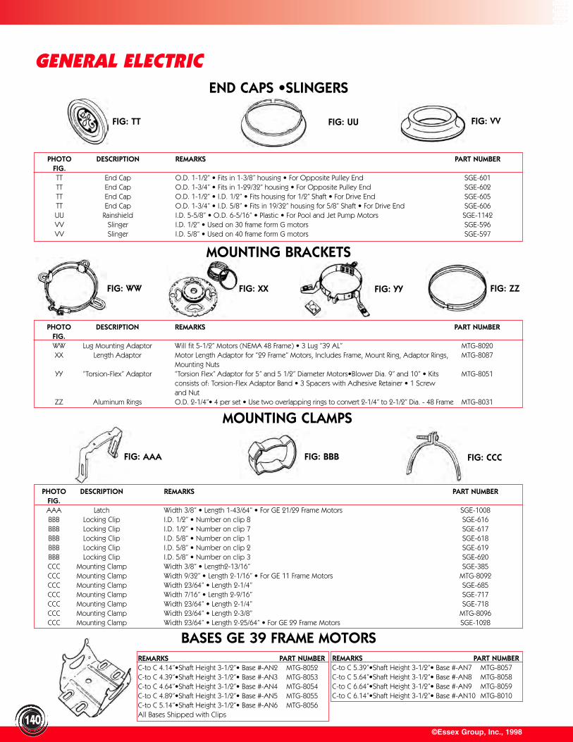
FIG: AAA FIG: BBB FIG: CCC
FIG: TT FIG: UU FIG: VV
©Essex Group, Inc., 1998140
GENERAL ELECTRICEND CAPS •SLINGERS
MOUNTING CLAMPS
BASES GE 39 FRAME MOTORS
PHOTO DESCRIPTION REMARKS PART NUMBERFIG.TT End Cap O.D. 1-1/2” • Fits in 1-3/8” housing • For Opposite Pulley End SGE-601TT End Cap O.D. 1-3/4” • Fits in 1-29/32” housing • For Opposite Pulley End SGE-602TT End Cap O.D. 1-1/2” • I.D. 1/2” • Fits housing for 1/2” Shaft • For Drive End SGE-605TT End Cap O.D. 1-3/4” • I.D. 5/8” • Fits in 19/32” housing for 5/8” Shaft • For Drive End SGE-606UU Rainshield I.D. 5-5/8” • O.D. 6-5/16” • Plastic • For Pool and Jet Pump Motors SGE-1142VV Slinger I.D. 1/2” • Used on 30 frame form G motors SGE-596VV Slinger I.D. 5/8” • Used on 40 frame form G motors SGE-597
PHOTO DESCRIPTION REMARKS PART NUMBERFIG.WW Lug Mounting Adaptor Will fit 5-1/2” Motors (NEMA 48 Frame) • 3 Lug “39 AL” MTG-8020XX Length Adaptor Motor Length Adaptor for “29 Frame” Motors, Includes Frame, Mount Ring, Adaptor Rings, MTG-8087
Mounting NutsYY “Torsion-Flex” Adaptor “Torsion Flex” Adaptor for 5” and 5 1/2” Diameter Motors•Blower Dia. 9” and 10” • Kits MTG-8051
consists of: Torsion-Flex Adaptor Band • 3 Spacers with Adhesive Retainer • 1 Screw and Nut
ZZ Aluminum Rings O.D. 2-1/4”• 4 per set • Use two overlapping rings to convert 2-1/4” to 2-1/2” Dia. - 48 Frame MTG-8031
PHOTO DESCRIPTION REMARKS PART NUMBERFIG.AAA Latch Width 3/8” • Length 1-43/64” • For GE 21/29 Frame Motors SGE-1008BBB Locking Clip I.D. 1/2” • Number on clip 8 SGE-616BBB Locking Clip I.D. 1/2” • Number on clip 7 SGE-617BBB Locking Clip I.D. 5/8” • Number on clip 1 SGE-618BBB Locking Clip I.D. 5/8” • Number on clip 2 SGE-619BBB Locking Clip I.D. 5/8” • Number on clip 3 SGE-620CCC Mounting Clamp Width 3/8” • Length2-13/16” SGE-385CCC Mounting Clamp Width 9/32” • Length 2-1/16” • For GE 11 Frame Motors MTG-8092CCC Mounting Clamp Width 23/64” • Length 2-1/4” SGE-685CCC Mounting Clamp Width 7/16” • Length 2-9/16” SGE-717CCC Mounting Clamp Width 23/64” • Length 2-1/4” SGE-718CCC Mounting Clamp Width 23/64” • Length 2-3/8” MTG-8096CCC Mounting Clamp Width 23/64” • Length 2-25/64” • For GE 29 Frame Motors SGE-1028
REMARKS PART NUMBERC-to C 4.14”•Shaft Height 3-1/2”• Base #-AN2 MTG-8052C-to C 4.39”•Shaft Height 3-1/2”• Base #-AN3 MTG-8053C-to C 4.64”•Shaft Height 3-1/2”• Base #-AN4 MTG-8054C-to C 4.89”•Shaft Height 3-1/2”• Base #-AN5 MTG-8055C-to C 5.14”•Shaft Height 3-1/2”• Base #-AN6 MTG-8056All Bases Shipped with Clips
REMARKS PART NUMBERC-to C 5.39”•Shaft Height 3-1/2”• Base #-AN7 MTG-8057C-to C 5.64”•Shaft Height 3-1/2”• Base #-AN8 MTG-8058C-to C 6.64”•Shaft Height 3-1/2”• Base #-AN9 MTG-8059C-to C 6.14”•Shaft Height 3-1/2”• Base #-AN10 MTG-8010
MOUNTING BRACKETS
FIG: WW FIG: XX FIG: YY FIG: ZZ
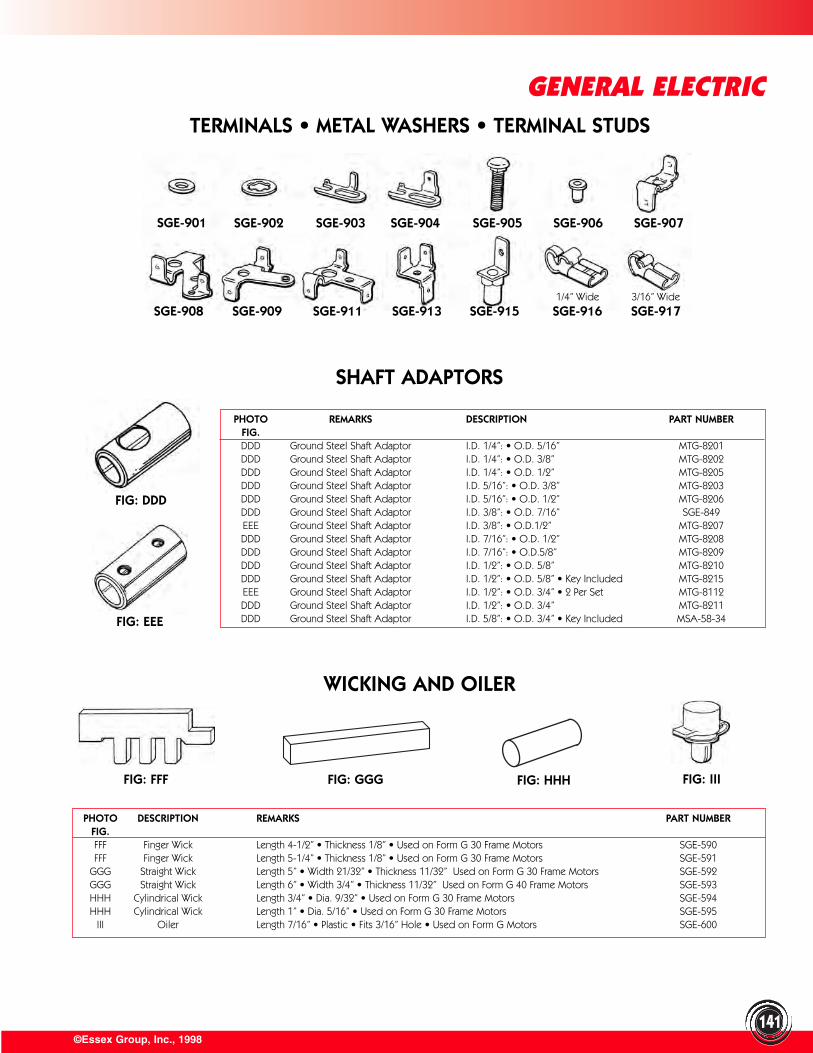
©Essex Group, Inc., 1998141
GENERAL ELECTRICTERMINALS • METAL WASHERS • TERMINAL STUDS
SHAFT ADAPTORS
PHOTO REMARKS DESCRIPTION PART NUMBERFIG.DDD Ground Steel Shaft Adaptor I.D. 1/4”: • O.D. 5/16” MTG-8201DDD Ground Steel Shaft Adaptor I.D. 1/4”: • O.D. 3/8” MTG-8202DDD Ground Steel Shaft Adaptor I.D. 1/4”: • O.D. 1/2” MTG-8205DDD Ground Steel Shaft Adaptor I.D. 5/16”: • O.D. 3/8” MTG-8203DDD Ground Steel Shaft Adaptor I.D. 5/16”: • O.D. 1/2” MTG-8206DDD Ground Steel Shaft Adaptor I.D. 3/8”: • O.D. 7/16” SGE-849EEE Ground Steel Shaft Adaptor I.D. 3/8”: • O.D.1/2” MTG-8207DDD Ground Steel Shaft Adaptor I.D. 7/16”: • O.D. 1/2” MTG-8208DDD Ground Steel Shaft Adaptor I.D. 7/16”: • O.D.5/8” MTG-8209DDD Ground Steel Shaft Adaptor I.D. 1/2”: • O.D. 5/8” MTG-8210DDD Ground Steel Shaft Adaptor I.D. 1/2”: • O.D. 5/8” • Key Included MTG-8215EEE Ground Steel Shaft Adaptor I.D. 1/2”: • O.D. 3/4” • 2 Per Set MTG-8112DDD Ground Steel Shaft Adaptor I.D. 1/2”: • O.D. 3/4” MTG-8211DDD Ground Steel Shaft Adaptor I.D. 5/8”: • O.D. 3/4” • Key Included MSA-58-34
PHOTO DESCRIPTION REMARKS PART NUMBERFIG.FFF Finger Wick Length 4-1/2” • Thickness 1/8” • Used on Form G 30 Frame Motors SGE-590FFF Finger Wick Length 5-1/4” • Thickness 1/8” • Used on Form G 30 Frame Motors SGE-591
GGG Straight Wick Length 5” • Width 21/32” • Thickness 11/32” Used on Form G 30 Frame Motors SGE-592GGG Straight Wick Length 6” • Width 3/4” • Thickness 11/32” Used on Form G 40 Frame Motors SGE-593HHH Cylindrical Wick Length 3/4” • Dia. 9/32” • Used on Form G 30 Frame Motors SGE-594HHH Cylindrical Wick Length 1” • Dia. 5/16” • Used on Form G 30 Frame Motors SGE-595
III Oiler Length 7/16” • Plastic • Fits 3/16” Hole • Used on Form G Motors SGE-600
WICKING AND OILER
SGE-901 SGE-902 SGE-903 SGE-904 SGE-905 SGE-906 SGE-907
SGE-908 SGE-909 SGE-911 SGE-913 SGE-915 SGE-916 SGE-9171/4” Wide 3/16” Wide
FIG: EEE
FIG: FFF FIG: IIIFIG: HHHFIG: GGG
FIG: DDD
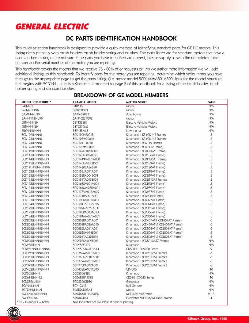
©Essex Group, Inc., 1998142
GENERAL ELECTRIC
BREAKDOWN OF GE MODEL NUMBERS
This quick selection handbook is designed to provide a quick method of identifying standard parts for GE DC motors. Thislisting deals primarily with brush holders brush holder spring and brushes. The parts listed are for standard motors that have anon standard motor, or are not sure if the parts you have identified are correct, please supply us with the complete modelnumber and/or serial number of the motor you are repairing.
This handbook covers the motors that we receive 75 - 80% of or requests on. As we gather more information we will addadditional listings to this handbook. To identify parts for the motor you are repairing, determine which series motor you havethen go to the appropriate page to get the parts listing, (i.e. motor model 5CD144WA801A800) look for the model structurethat begins with 5CD144 ... this is a Kinamatic II proceed to page 5 of this handbook for a listing of the brush holder, brushholder spring and standard brushes.
MODEL STRUCTURE * EXAMPLE MODEL MOTOR SERIES PAGE34LNNN 34B615 Motor N/A36LNNNNNN 36X958083 Motor N/A5AMNNNLNN 5AM602B23 Amplidyne N/A5ANNNNLNLNN 5AN102B1G02 Motor N/A5BTNNNNLN 5BT1328B7 Electric Vehicle Motors N/A5BTNNNNLN 5BT2379M2 Electric Vehicle Motors N/A5BYNNNLNNN 5BY435A65 Low Inertia N/A5CD122LLNNNL 5CD122HE001B Kinamatic II K3 (CD146 Frame) 55CD123LLNNNL 5CD123WE001B Kinamatic II K3 (CD148 Frame) 55CD124LLNNNL 5CD124TP001B Kinamatic II (CD149 Frame) 55CD125LLNNNL 5CD125WE001B Kinamatic II (CD1412 Frame) 55CD142LLNNNLNNN 5CD142FE012B008 Kinamatic II (CDL182AT Frame) 55CD143LLNNNLNNN 5CD143LC007B021 Kinamatic II (CD186AT Frame) 55CD144LLNNNLNNN 5CD144WA801A800 Kinamatic II (CDL186AT Frame) 55CD145LLNNNLNNN 5CD145UA030B001 Kinamatic II (CD189AT Frame) 55CD14LNNLNNNNNN 5CD14E03A36630 Kinamatic II (CD180AT Frame) 55CD152LLNNNLNNN 5CD152JA001A001 Kinamatic II (CD218AT Frame) 55CD153LLNNNLNNN 5CD153RA004B001 Kinamatic II (CD219AT Frame) 55CD154LLNNNLNNN 5CD154TA003B001 Kinamatic II (CD2110AT Frame) 55CD163LLNNNLNNN 5CD163SA001A001 Kinamatic II (CD258AT Frame) 55CD164LLNNNLNNN 5CD164MA055A001 Kinamatic II (CD259AT Frame) 55CD173LLNNNLNNN 5CD173VA018A009 Kinamatic II (CD287AT Frame) 55CD174LLNNNLNNN 5CD174RA001A001 Kinamatic II (CD288ATFrame) 55CD183LLNNNLNNN 5CD183KA001A001 Kinamatic II (CD327AT Frame) 55CD184LLNNNLNNN 5CD184TA013A026 Kinamatic II (CD328AT Frame) 55CD192LLNNNLNNN 5CD192NA027A031 Kinamatic II (CD365AT Frame) 55CD193LLNNNLNNN 5CD193PA003A013 Kinamatic II (CD366AT Frame) 55CD194LLNNNLNNN 5CD194MA001A001 Kinamatic II (CD360AT Frame) 55CD203LLNNNLNNN 5CD203PA001A001 Kinamatic II (CD407AT& CDL407AT Frame) 65CD204LLNNNLNNN 5CD204PA086A010 Kinamatic II (CD409AT & CDL409AT Frame) 65CD222LLNNNLNNN 5CD222LA001A001 Kinamatic II (CD504AT & CDL504AT Frame) 65CD223LLNNNLNNN 5CD223SA074B001 Kinamatic II (CD506AT & CDL506AT Frame) 65CD224LLNNNLNNN 5CD224TA032B012 Kinamatic II (CD508AT & CDL508AT Frame) 65CD226LLNNNLNNN 5CD226SA002B003 Kinamatic II (CD5010ATZ Frame) N/A5CD256LNNN 5CD256G177 Kinamatic I N/A5CD25LNNLNNNNNN 5CD25D26G001513 CD5000 - CD9000 Series 95CD362LLNNNLNNN 5CD362MA001A001 Kinamatic II (CD2512AT Frame) 65CD363LLNNNLNNN 5CD363NA001A001 Kinamatic II (CD2513AT Frame) 65CD372LLNNNLNNN 5CD372MA001A001 Kinamatic II (CD2812AT Frame) 65CD373LLNNNLNNN 5CD373PA002A001 Kinamatic II (CD2813AT Frame) 65CD432LLNNNLNNN 5CD432EA001C800 CD4000 105CD505LNNN 5CD505G329 Kinamatic I N/A5CD684LNNNLL 5CD684E143BE CD580 -CD680 Series 105CDS326LNNN 5CDS326G230 Generator N/A5CYNNNNLN 5CY1031E1 Roll Grinder N/A5GTENNLNNLN 5GTE20D03A1 Motor N/A5MD020LNNNNNLL 5MD020D114100SD Mill Duty 600 Frame 2 - 35MD824LNN 5MD824A3 Excavator Mill Duty MDP800 Frame 4
* N = Number L = Letter N/A Indicates not available at time of printing
DC PARTS IDENTIFICATION HANDBOOK
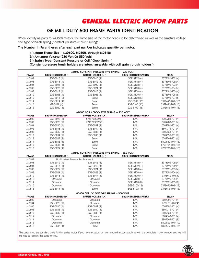
©Essex Group, Inc., 1998143
GENERAL ELECTRIC MOTOR PARTSGE MILL DUTY 600 FRAME PARTS IDENTIFICATION
When identifying parts for MD600 motors, the frame size of the motor needs to be determined as well as the armature voltageand type of brush spring (constant pressure or clock spring).
The Number In Parentheses after each part number indicates quantity per motor.
1.) Motor Frame Size -- (MD600, MD602, through MD618)2.) Armature Voltage (230 Volt Or 550 Volt)3.) Spring Type (Constant Pressure or Coil / Clock Spring )(Constant pressure brush holders are interchangeable with coil spring brush holders.)
MD600 CONSTANT PRESSURE TYPE SPRING -- 230 VOLTFRAME BRUSH HOLDER (RH) BRUSH HOLDER (LH) BRUSH HOLDER SPRING BRUSHMD602 SGE-5015 (1) SGE-5016 (1) SGE-5112 (4) 337B696-P02 (4)MD603 SGE-5015 (1) SGE-5016 (1) SGE-5112 (4) 337B696-P02 (4)MD604 SGE-5021 (1) SGE-5022 (1) SGE-5108 (4) 337B696-P03 (4)MD606 SGE-5023 (1) SGE-5024 (1) SGE-5100 (4) 337B696-P04 (4)MD608 SGE-5017 (1) SGE-5018 (1) SGE-5100 (4) 337B696-P05 (4)MD610 SGE-5025 (1) SGE-5026 (1) SGE-5100 (4) 337B696-P08 (6)MD612 SGE-5011 (2) Same SGE-5100 (6) 337B696-P07 (6)MD614 SGE-5014 (4) Same SGE-5100 (16) 337B696-P08 (16)MD616 GE-5019 (4) Same SGE-5100 (16) 337B696-P07 (16)MD618 SGE-5020 (4) Same SGE-5100 (16) 337B696-P09 (16)
MD600 COIL / CLOCK TYPE SPRING -- 230 VOLTFRAME BRUSH HOLDER (RH) BRUSH HOLDER (LH) BRUSH HOLDER SPRING BRUSHMD602 SGE-5028 (1) 6748708G02 (1) N/A 6709783-P01 (4)MD603 SGE-5028 (1) 6748708G02 (1) N/A 6709783-P01 (4)MD604 SGE-5030 (1) SGE-5031 (1) N/A 6709786-P01 (4)MD606 SGE-5038 (1) SGE-5039 (1) N/A 8809716-P01 (4)MD608 SGE-5032 (1) SGE-5033 (1) N/A 8809563-P01 (4)MD610 SGE-5034 (1) SGE-5035 (1) N/A 8809552-P01 (6)MD612 SGE-5027 (2) Same N/A 6709764-P01 (6)MD614 SGE-5036 (4) Same N/A 8809552-P01 (16)MD616 SGE-5037 (4) Same N/A 6709764-P01 (16)MD618 SGE-5029 (4) Same N/A 6709776-P01 (16)
MD600 CONSTANT PRESSURE TYPE SPRING -- 550 VOLTFRAME BRUSH HOLDER (RH) BRUSH HOLDER (LH) BRUSH HOLDER SPRING BRUSHMD602 No Constant Pressure ReplacementMD603 SGE-5016 (1) SGE-5015 (1) SGE-5112 (4) 337B696-P02 (4)MD604 SGE-5016 (1) SGE-5015 (1) SGE-5112 (4) 337B696-P02 (4)MD606 SGE-5022 (1) SGE-5021 (1) SGE-5108 (4) 337B696-P03 (4)MD608 SGE-5024 (1) SGE-5023 (1) SGE-5100 (4) 337B696-P04 (4)MD610 SGE-5018 (1) SGE-5017 (1) SGE-5100 (4) 337B696-P05(4)MD612 Obsolete Obsolete SGE-5100 (4) 337B696-P05 (4)MD614 Obsolete Obsolete SGE-5100 (8) 337B696-P05 (8)MD616 Obsolete Obsolete SGE-5100(12) 337B696-P08 (12)MD618 SGE-5014 (4) Same SGE-5100(16) 337B696-P08 (16)
MD600 COIL / CLOCK TYPE SPRING -- 550 VOLTFRAME BRUSH HOLDER (RH) BRUSH HOLDER (LH) BRUSH HOLDER SPRING BRUSHMD602 Obsolete Obsolete N/A 8807309-P01 (4)MD604 SGE-5028 (1) Obsolete N/A 6709783-P01(4)MD606 SGE-5030 (1) SGE-5031 (1) N/A 6709786-P01 (4)MD608 SGE-5038 (1) SGE-5039 (1) N/A 8809716-P01 (4)MD610 SGE-5032 (1) SGE-5033 (1) N/A 8809563-P01 (4)MD612 Obsolete Obsolete N/A 8809563-P01 (4)MD614 Obsolete Obsolete N/A 8809563-P01 (8)MD616 Obsolete Obsolete N/A 8809522-P01 (12)MD618 SGE-5036 (4) Same N/A 8809522-P01 (16)
The parts listed are standard parts for that series motor, if you have a custom or non standard motor supply us with the complete motor number and we willbe glad to identify the parts for you.
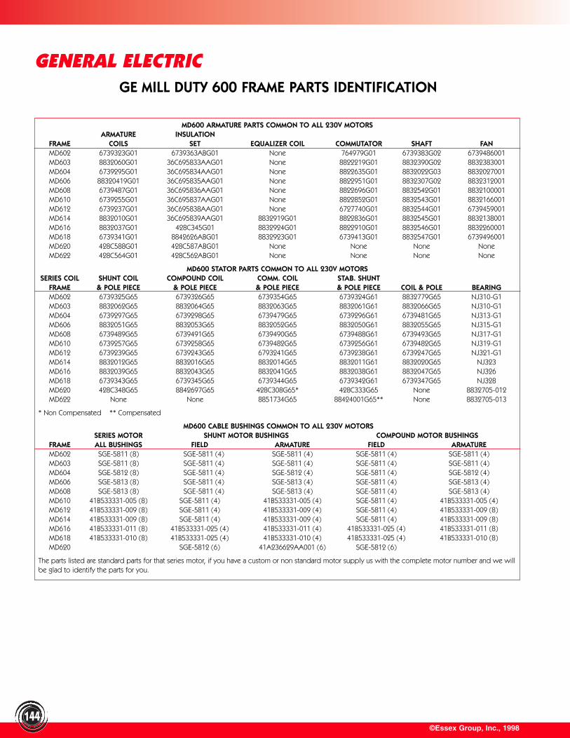
©Essex Group, Inc., 1998144
GENERAL ELECTRIC
MD600 ARMATURE PARTS COMMON TO ALL 230V MOTORSARMATURE INSULATION
FRAME COILS SET EQUALIZER COIL COMMUTATOR SHAFT FANMD602 6739323G01 6739363ABG01 None 764979G01 6739383G02 6739486001MD603 8832060G01 36C695833AAG01 None 8822219G01 8832390G02 8832383001MD604 6739295G01 36C695834AAG01 None 8822635G01 8832022G03 8832027001MD606 88320419G01 36C695835AAG01 None 8822951G01 8832307G02 8832312001MD608 6739487G01 36C695836AAG01 None 8822696G01 8832542G01 8832100001MD610 6739255G01 36C695837AAG01 None 8822852G01 8832543G01 8832166001MD612 6739237G01 36C695838AAG01 None 6727740G01 8832544G01 6739459001MD614 8832010G01 36C695839AAG01 8832919G01 8822836G01 8832545G01 8832138001MD616 8832037G01 428C345G01 8832924G01 8822910G01 8832546G01 8832260001MD618 6739341G01 8842626ABG01 8832923G01 6739413G01 8832547G01 6739496001MD620 428C588G01 428C587ABG01 None None None NoneMD622 428C564G01 428C562ABG01 None None None None
MD600 STATOR PARTS COMMON TO ALL 230V MOTORSSERIES COIL SHUNT COIL COMPOUND COIL COMM. COIL STAB. SHUNT
FRAME & POLE PIECE & POLE PIECE & POLE PIECE & POLE PIECE COIL & POLE BEARINGMD602 6739325G65 6739326G65 6739354G65 6739324G61 8832779G65 NJ310-G1MD603 8832062G65 8832064G65 8832063G65 8832061G61 8832066G65 NJ310-G1MD604 6739297G65 6739298G65 6739479G65 6739296G61 6739481G65 NJ313-G1MD606 8832051G65 8832053G65 8832052G65 8832050G61 8832055G65 NJ315-G1MD608 6739489G65 6739491G65 6739490G65 6739488G61 6739493G65 NJ317-G1MD610 6739257G65 6739258G65 6739482G65 6739256G61 6739482G65 NJ319-G1MD612 6739239G65 6739243G65 6793241G65 6739238G61 6739247G65 NJ321-G1MD614 8832012G65 8832016G65 8832014G65 8832011G61 8832020G65 NJ323MD616 8832039G65 8832043G65 8832041G65 8832038G61 8832047G65 NJ326MD618 6739343G65 6739345G65 6739344G65 6739342G61 6739347G65 NJ328MD620 428C348G65 8842697G65 428C308G65* 428C333G65 None 8832705-012MD622 None None 8851734G65 88424001G65** None 8832705-013
* Non Compensated ** Compensated
MD600 CABLE BUSHINGS COMMON TO ALL 230V MOTORSSERIES MOTOR SHUNT MOTOR BUSHINGS COMPOUND MOTOR BUSHINGS
FRAME ALL BUSHINGS FIELD ARMATURE FIELD ARMATUREMD602 SGE-5811 (8) SGE-5811 (4) SGE-5811 (4) SGE-5811 (4) SGE-5811 (4)MD603 SGE-5811 (8) SGE-5811 (4) SGE-5811 (4) SGE-5811 (4) SGE-5811 (4)MD604 SGE-5812 (8) SGE-5811 (4) SGE-5812 (4) SGE-5811 (4) SGE-5812 (4)MD606 SGE-5813 (8) SGE-5811 (4) SGE-5813 (4) SGE-5811 (4) SGE-5813 (4)MD608 SGE-5813 (8) SGE-5811 (4) SGE-5813 (4) SGE-5811 (4) SGE-5813 (4)MD610 41B533331-005 (8) SGE-5811 (4) 41B533331-005 (4) SGE-5811 (4) 41B533331-005 (4)MD612 41B533331-009 (8) SGE-5811 (4) 41B533331-009 (4) SGE-5811 (4) 41B533331-009 (8)MD614 41B533331-009 (8) SGE-5811 (4) 41B533331-009 (4) SGE-5811 (4) 41B533331-009 (8)MD616 41B533331-011 (8) 41B533331-025 (4) 41B533331-011 (4) 41B533331-025 (4) 41B533331-011 (8)MD618 41B533331-010 (8) 41B533331-025 (4) 41B533331-010 (4) 41B533331-025 (4) 41B533331-010 (8)MD620 SGE-5812 (6) 41A236629AA001 (6) SGE-5812 (6)
The parts listed are standard parts for that series motor, if you have a custom or non standard motor supply us with the complete motor number and we willbe glad to identify the parts for you.
GE MILL DUTY 600 FRAME PARTS IDENTIFICATION
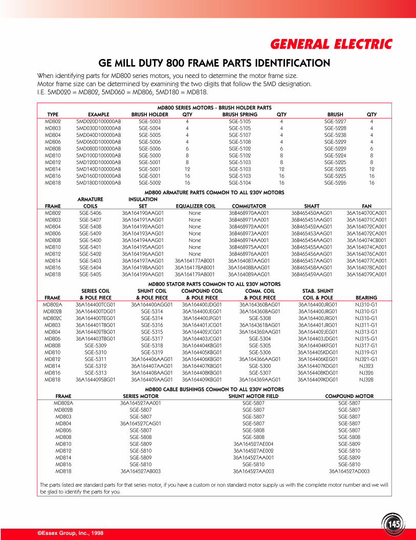
©Essex Group, Inc., 1998
GENERAL ELECTRIC
145
GE MILL DUTY 800 FRAME PARTS IDENTIFICATIONWhen identifying parts for MD800 series motors, you need to determine the motor frame size.Motor frame size can be determined by examining the two digits that follow the 5MD designation.I.E. 5MD020 = MD802, 5MD060 = MD806, 5MD180 = MD818.
MD800 SERIES MOTORS - BRUSH HOLDER PARTSTYPE EXAMPLE BRUSH HOLDER QTY BRUSH SPRING QTY BRUSH QTY
MD802 5MD020D100000AB SGE-5003 4 SGE-5105 4 SGE-5227 4MD803 5MD030D100000AB SGE-5004 4 SGE-5105 4 SGE-5228 4MD804 5MD040D100000AB SGE-5005 4 SGE-5107 4 SGE-5238 4MD806 5MD060D100000AB SGE-5006 4 SGE-5108 4 SGE-5229 4MD808 5MD080D100000AB SGE-5006 6 SGE-5102 6 SGE-5229 6MD810 5MD100D100000AB SGE-5000 8 SGE-5102 8 SGE-5224 8MD812 5MD120D100000AB SGE-5001 8 SGE-5103 8 SGE-5225 8MD814 5MD140D100000AB SGE-5001 12 SGE-5103 12 SGE-5225 12MD816 5MD160D100000AB SGE-5001 16 SGE-5103 16 SGE-5225 16MD818 5MD180D100000AB SGE-5002 16 SGE-5104 16 SGE-5226 16
MD800 ARMATURE PARTS COMMON TO ALL 230V MOTORSARMATURE INSULATION
FRAME COILS SET EQUALIZER COIL COMMUTATOR SHAFT FANMD802 SGE-5406 36A164190AAG01 None 36B468970AA001 36B465450AAG01 36A164070CA001MD803 SGE-5407 36A164191AAG01 None 36B468971AA001 36B465451AAG01 36A164071CA001MD804 SGE-5408 36A164192AAG01 None 36B468972AA001 36B465452AAG01 36A164072CA001MD806 SGE-5409 36A164193AAG01 None 36B468973AA001 36B465453AAG01 36A164072CA001MD808 SGE-5400 36A164194AAG01 None 36B468974AA001 36B465454AAG01 36A164074CB001MD810 SGE-5401 36A164195AAG01 None 36B468975AA001 36B465455AAG01 36A164074CA001MD812 SGE-5402 36A164196AAG01 None 36B468976AA001 36B465456AAG01 36A164076CA001MD814 SGE-5403 36A164197AAG01 36A164177AB001 36A164087AAG01 36B465457AAG01 36A164077CA001MD816 SGE-5404 36A164198AAG01 36A164178AB001 36A164088AAG01 36B465458AAG01 36A164078CA001MD818 SGE-5405 36A164199AAG01 36A164179AB001 36A164089AAG01 36B465459AAG01 36A164079CA001
MD800 STATOR PARTS COMMON TO ALL 230V MOTORSSERIES COIL SHUNT COIL COMPOUND COIL COMM. COIL STAB. SHUNT
FRAME & POLE PIECE & POLE PIECE & POLE PIECE & POLE PIECE COIL & POLE BEARINGMD802A 36A164400TCG01 36A164400AGG01 36A164400JDG01 36A164360BAG01 36A164400JRG01 NJ310-G1MD802B 36A164400TDG01 SGE-5314 36A164400JEG01 36A164360BAG01 36A164400JRG01 NJ310-G1MD802C 36A164400TEG01 SGE-5314 36A164400JFG01 SGE-5308 36A164400JRG01 NJ310-G1MD803 36A164401TBG01 SGE-5316 36A164401JCG01 36A164361BAG01 36A164401JRG01 NJ311-G1MD804 36A164402TBG01 SGE-5315 36A164402JCG01 36A164362AAG01 36A164402JEG01 NJ313-G1MD806 36A164403TBG01 SGE-5317 36A164403JCG01 SGE-5304 36A164403JDG01 NJ315-G1MD808 SGE-5309 SGE-5318 36A164404KBG01 SGE-5305 36A164404KFG01 NJ317-G1MD810 SGE-5310 SGE-5319 36A164405KBG01 SGE-5306 36A164405KDG01 NJ319-G1MD812 SGE-5311 36A164406AAG01 36A164406KBG01 36A164366AAG01 36A164406KEG01 NJ321-G1MD814 SGE-5312 36A164407AAG01 36A164407KBG01 SGE-5300 36A164407KDG01 NJ323MD816 SGE-5313 36A164408AAG01 36A164408KBG01 SGE-5307 36A164408KDG01 NJ326MD818 36A164409SBG01 36A164409AAG01 36A164409KBG01 36A164369AAG01 36A164409KDG01 NJ328
MD800 CABLE BUSHINGS COMMON TO ALL 230V MOTORSFRAME SERIES MOTOR SHUNT MOTOR FIELD COMPOUND MOTOR
MD802A 36A164527AA001 SGE-5807 SGE-5807MD802B SGE-5807 SGE-5807 SGE-5807MD803 SGE-5807 SGE-5807 SGE-5807MD804 36A164527CAG01 SGE-5807 SGE-5807MD806 SGE-5807 SGE-5808 SGE-5807MD808 SGE-5808 SGE-5808 SGE-5808MD810 SGE-5809 36A164527AE004 SGE-5809MD812 SGE-5810 36A164527AE002 SGE-5810MD814 SGE-5809 36A164527AA001 SGE-5809MD816 SGE-5810 SGE-5810 SGE-5810MD818 36A164527AB003 36A164527AA003 36A164527AD003
The parts listed are standard parts for that series motor, if you have a custom or non standard motor supply us with the complete motor number and we willbe glad to identify the parts for you.
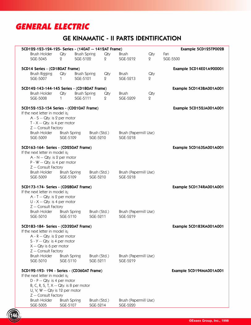
©Essex Group, Inc., 1998
GENERAL ELECTRIC
146
GE KINAMATIC - II PARTS IDENTIFICATION
5CD122-123-124-125- Series - (140AT -- 1412AT Frame) Example 5CD125TP002BBrush Holder Qty Brush Spring Qty Brush Qty FanSGE-5045 2 SGE-5122 2 SGE-5212 2 SGE-5500
5CD14 Series - (CD180AT Frame) Example 5CD14E01A900001Brush Rigging Qty Brush Spring Qty Brush QtySGE-5007 1 SGE-5101 2 SGE-5213 2
5CD142-143-144-145 Series - (CD180AT Frame) Example 5CD143BA001A001Brush Holder Qty Brush Spring Qty Brush QtySGE-5008 1 SGE-5111 2 SGE-5209 2
5CD152-153-154 Series - (CD210AT Frame) Example 5CD152JA001A001If the next letter in model is;
A - S -- Qty. is 2 per motorT - X -- Qty. is 4 per motorZ -- Consult FactoryBrush Holder Brush Spring Brush (Std.) Brush (Papermill Use)SGE-5009 SGE-5109 SGE-5210 SGE-5218
5CD163-164- Series - (CD250AT Frame) Example 5CD163SA001A001If the next letter in model is;
A - N -- Qty. is 2 per motorP - W -- Qty. is 4 per motorZ -- Consult FactoryBrush Holder Brush Spring Brush (Std.) Brush (Papermill Use)SGE-5009 SGE-5109 SGE-5210 SGE-5218
5CD173-174- Series - (CD280AT Frame) Example 5CD174RA001A001If the next letter in model is;
A - T -- Qty. is 2 per motorU - X -- Qty. is 4 per motorZ -- Consult FactoryBrush Holder Brush Spring Brush (Std.) Brush (Papermill Use)SGE-5010 SGE-5110 SGE-5211 SGE-5219
5CD183-184- Series - (CD320AT Frame) Example 5CD183KA001A001If the next letter in model is;
A - R -- Qty. is 2 per motorS - Y -- Qty. is 4 per motorX -- Qty is 6 per motorZ -- Consult FactoryBrush Holder Brush Spring Brush (Std.) Brush (Papermill Use)SGE-5010 SGE-5110 SGE-5211 SGE-5219
5CD192-193- 194 - Series - (CD360AT Frame) Example 5CD194MA001A001If the next letter in model is;
D - P -- Qty. is 4 per motorB, C, R, S, T, X -- Qty. is 8 per motorU, V, W -- Qty is 12 per motorZ -- Consult FactoryBrush Holder Brush Spring Brush (Std.) Brush (Papermill Use)SGE-5005 SGE-5107 SGE-5214 SGE-5220
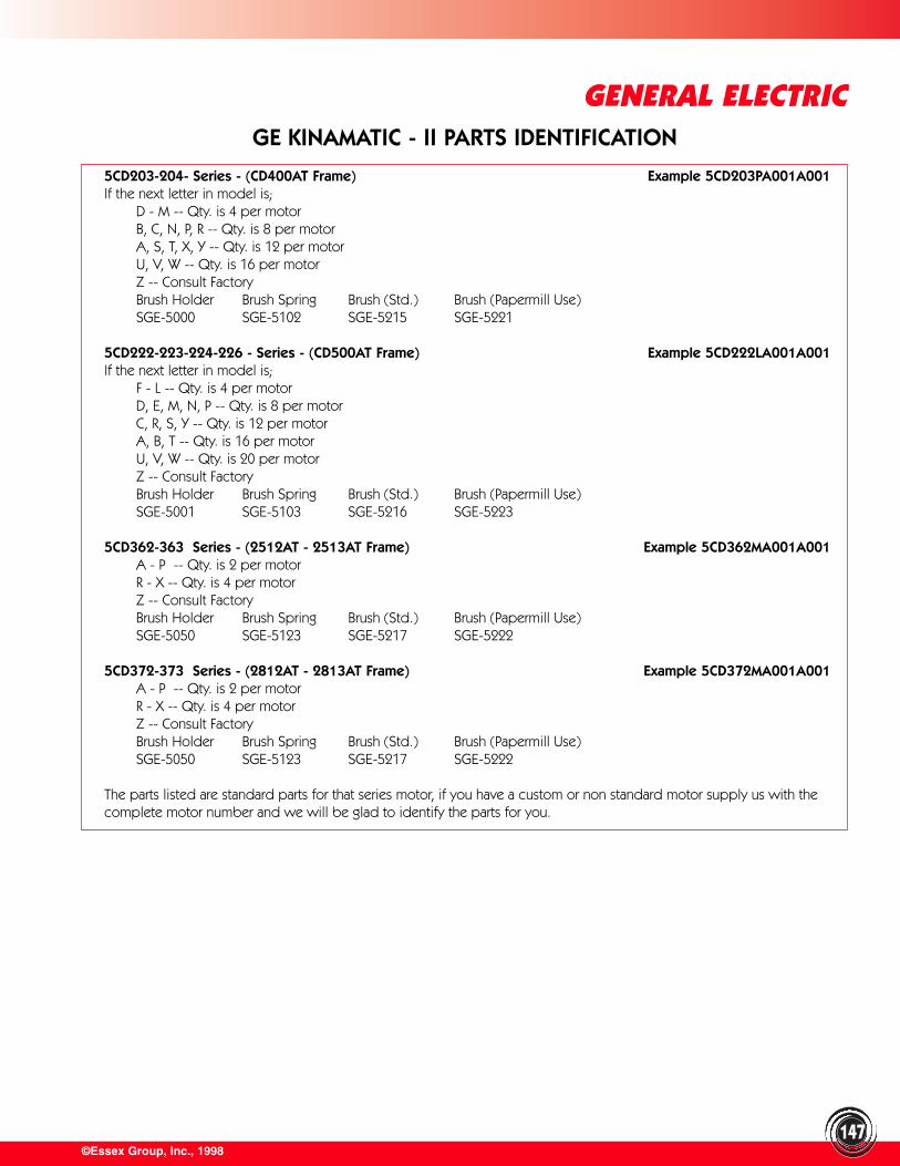
©Essex Group, Inc., 1998
GENERAL ELECTRIC
147
5CD203-204- Series - (CD400AT Frame) Example 5CD203PA001A001If the next letter in model is;
D - M -- Qty. is 4 per motorB, C, N, P, R -- Qty. is 8 per motorA, S, T, X, Y -- Qty. is 12 per motorU, V, W -- Qty. is 16 per motorZ -- Consult FactoryBrush Holder Brush Spring Brush (Std.) Brush (Papermill Use)SGE-5000 SGE-5102 SGE-5215 SGE-5221
5CD222-223-224-226 - Series - (CD500AT Frame) Example 5CD222LA001A001If the next letter in model is;
F - L -- Qty. is 4 per motorD, E, M, N, P -- Qty. is 8 per motorC, R, S, Y -- Qty. is 12 per motorA, B, T -- Qty. is 16 per motorU, V, W -- Qty. is 20 per motorZ -- Consult FactoryBrush Holder Brush Spring Brush (Std.) Brush (Papermill Use)SGE-5001 SGE-5103 SGE-5216 SGE-5223
5CD362-363 Series - (2512AT - 2513AT Frame) Example 5CD362MA001A001A - P -- Qty. is 2 per motorR - X -- Qty. is 4 per motorZ -- Consult FactoryBrush Holder Brush Spring Brush (Std.) Brush (Papermill Use)SGE-5050 SGE-5123 SGE-5217 SGE-5222
5CD372-373 Series - (2812AT - 2813AT Frame) Example 5CD372MA001A001A - P -- Qty. is 2 per motorR - X -- Qty. is 4 per motorZ -- Consult FactoryBrush Holder Brush Spring Brush (Std.) Brush (Papermill Use)SGE-5050 SGE-5123 SGE-5217 SGE-5222
The parts listed are standard parts for that series motor, if you have a custom or non standard motor supply us with thecomplete motor number and we will be glad to identify the parts for you.
GE KINAMATIC - II PARTS IDENTIFICATION
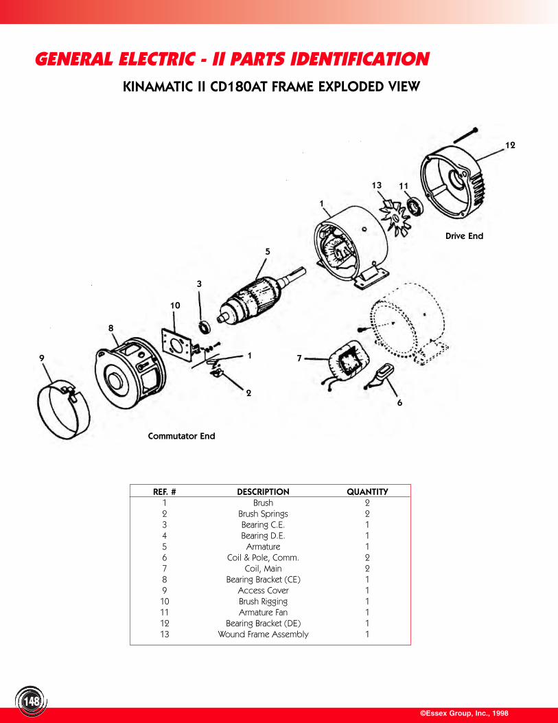
©Essex Group, Inc., 1998148
GENERAL ELECTRIC - II PARTS IDENTIFICATIONKINAMATIC II CD180AT FRAME EXPLODED VIEW
REF. # DESCRIPTION QUANTITY1 Brush 22 Brush Springs 23 Bearing C.E. 14 Bearing D.E. 15 Armature 16 Coil & Pole, Comm. 27 Coil, Main 28 Bearing Bracket (CE) 19 Access Cover 110 Brush Rigging 111 Armature Fan 112 Bearing Bracket (DE) 113 Wound Frame Assembly 1
1
2
10
3
5
8
9 7
6
1
13 11
12
Commutator End
Drive End
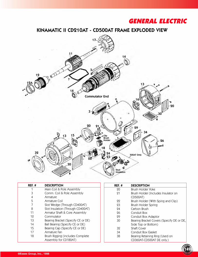
149©Essex Group, Inc., 1998
GENERAL ELECTRICKINAMATIC II CD210AT - CD500AT FRAME EXPLODED VIEW
REF. # DESCRIPTION1 Main Coil & Pole Assembly3 Comm. Coil & Pole Assembly4 Armature5 Armature Coil7 Slot Wedge (Through CD400AT)8 Slot Insulation (Through CD400AT)11 Armatur Shaft & Core Assembly12 Commutator13 Bearing Bracket (Specify CE or DE)14 Ball Bearing (Specify CE or DE)15 Bearing Cap (Specify CE or DE)17 Armature Fan18 Brush Rigging (includes Complete
Assembly for CD180AT)
REF. # DESCRIPTION20 Brush Holder Yoke21 Brush Holder (Includes Insulator on
CD500AT)22 Brush Holder (With Sping and Clip)23 Brush Holder Spring24 Carbon Brush26 Conduit Box29 Conduit Box Adaptor30 Bearing Bracket Covers (Specify DE or DE,
Side Top or Bottom)32 Shaft Cover34 Conduit Box Gasket38 Bearing Retaining Ring (Used on
CD360AT-CD500AT DE only.)
Commutator End
12A
12
11
13
32
4
14
87
17
?
14
30
15
20 21
18
242322
1
500AT Only
StudInsulation
26
3429
303
20
16
13
ClipBrushHolder
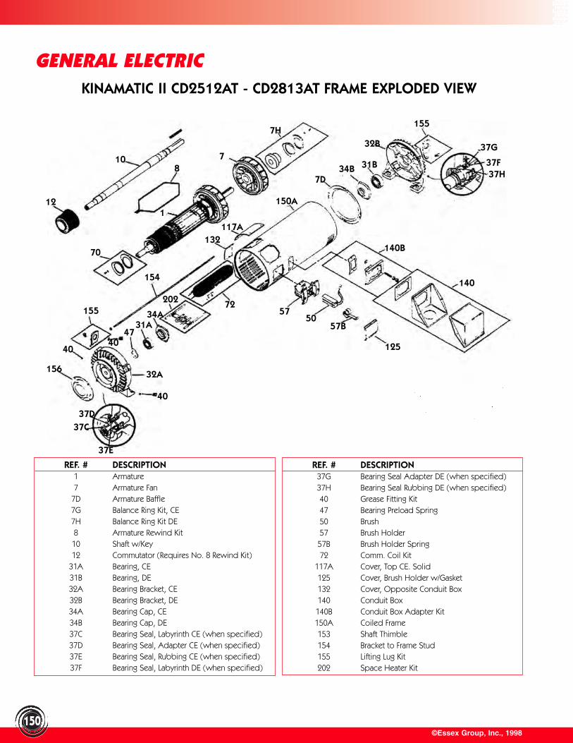
©Essex Group, Inc., 1998150
GENERAL ELECTRICKINAMATIC II CD2512AT - CD2813AT FRAME EXPLODED VIEW
REF. # DESCRIPTION1 Armature7 Armature Fan
7D Armature Baffle7G Balance Ring Kit, CE7H Balance Ring Kit DE8 Armature Rewind Kit
10 Shaft w/Key12 Commutator (Requires No. 8 Rewind Kit)
31A Bearing, CE31B Bearing, DE32A Bearing Bracket, CE32B Bearing Bracket, DE34A Bearing Cap, CE34B Bearing Cap, DE37C Bearing Seal, Labyrinth CE (when specified)37D Bearing Seal, Adapter CE (when specified)37E Bearing Seal, Rubbing CE (when specified)37F Bearing Seal, Labyrinth DE (when specified)
REF. # DESCRIPTION37G Bearing Seal Adapter DE (when specified)37H Bearing Seal Rubbing DE (when specified)40 Grease Fitting Kit47 Bearing Preload Spring50 Brush57 Brush Holder57B Brush Holder Spring72 Comm. Coil Kit
117A Cover, Top CE. Solid125 Cover, Brush Holder w/Gasket132 Cover, Opposite Conduit Box140 Conduit Box140B Conduit Box Adapter Kit150A Coiled Frame153 Shaft Thimble154 Bracket to Frame Stud155 Lifting Lug Kit202 Space Heater Kit
12
70
810
154
37D
4731A
34A
202 72
132117A
1
40
15632A
37C
40
37E
125
5750
57B
140
140B
150A
7D34B 31B
32B
155
37G
37F37H
7H
7
40
155
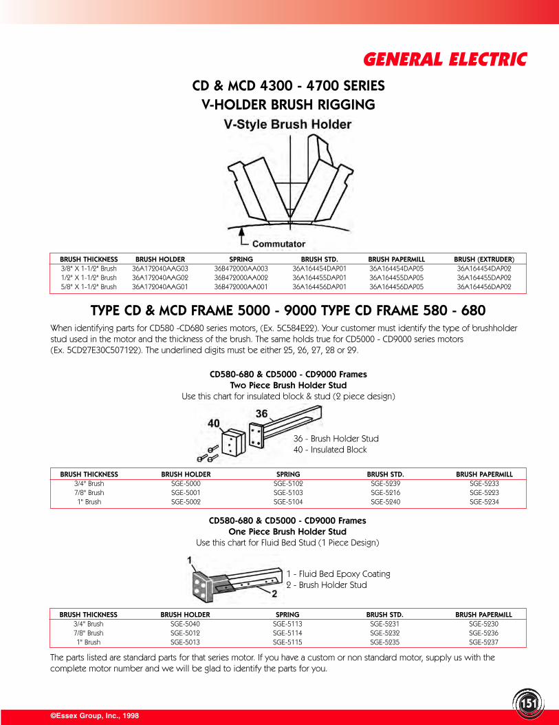
©Essex Group, Inc., 1998
GENERAL ELECTRIC
151
TYPE CD & MCD FRAME 5000 - 9000 TYPE CD FRAME 580 - 680
CD & MCD 4300 - 4700 SERIESV-HOLDER BRUSH RIGGING
When identifying parts for CD580 -CD680 series motors, (Ex. 5C584E22). Your customer must identify the type of brushholderstud used in the motor and the thickness of the brush. The same holds true for CD5000 - CD9000 series motors (Ex. 5CD27E30C507122). The underlined digits must be either 25, 26, 27, 28 or 29.
CD580-680 & CD5000 - CD9000 FramesTwo Piece Brush Holder Stud
Use this chart for insulated block & stud (2 piece design)
CD580-680 & CD5000 - CD9000 FramesOne Piece Brush Holder Stud
Use this chart for Fluid Bed Stud (1 Piece Design)
36 - Brush Holder Stud40 - Insulated Block
1 - Fluid Bed Epoxy Coating2 - Brush Holder Stud
BRUSH THICKNESS BRUSH HOLDER SPRING BRUSH STD. BRUSH PAPERMILL3/4" Brush SGE-5000 SGE-5102 SGE-5239 SGE-52337/8" Brush SGE-5001 SGE-5103 SGE-5216 SGE-52231" Brush SGE-5002 SGE-5104 SGE-5240 SGE-5234
BRUSH THICKNESS BRUSH HOLDER SPRING BRUSH STD. BRUSH PAPERMILL3/4" Brush SGE-5040 SGE-5113 SGE-5231 SGE-52307/8" Brush SGE-5012 SGE-5114 SGE-5232 SGE-52361" Brush SGE-5013 SGE-5115 SGE-5235 SGE-5237
The parts listed are standard parts for that series motor. If you have a custom or non standard motor, supply us with thecomplete motor number and we will be glad to identify the parts for you.
BRUSH THICKNESS BRUSH HOLDER SPRING BRUSH STD. BRUSH PAPERMILL BRUSH (EXTRUDER)3/8" X 1-1/2" Brush 36A172040AAG03 36B472000AA003 36A164454DAP01 36A164454DAP05 36A164454DAP021/2" X 1-1/2" Brush 36A172040AAG02 36B472000AA002 36A164455DAP01 36A164455DAP05 36A164455DAP025/8" X 1-1/2" Brush 36A172040AAG01 36B472000AA001 36A164456DAP01 36A164456DAP05 36A164456DAP02
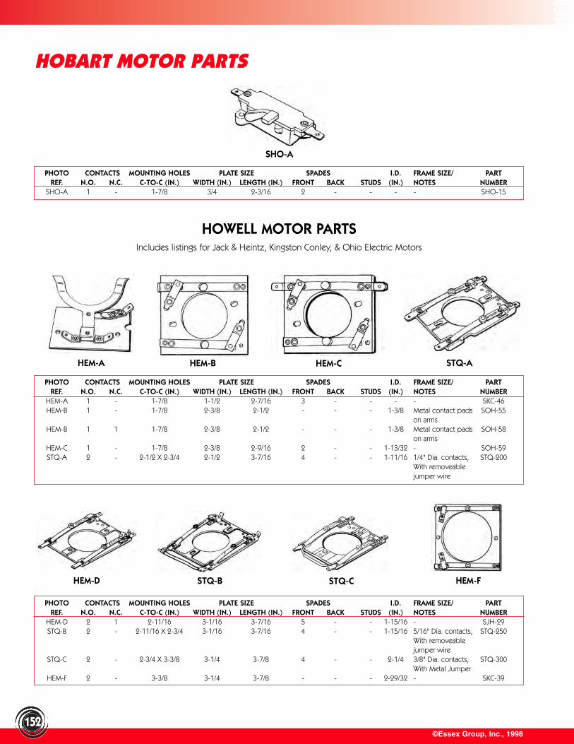
©Essex Group, Inc., 1998152
HOBART MOTOR PARTS
HOWELL MOTOR PARTSIncludes listings for Jack & Heintz, Kingston Conley, & Ohio Electric Motors
PHOTO CONTACTS MOUNTING HOLES PLATE SIZE SPADES I.D. FRAME SIZE/ PARTREF. N.O. N.C. C-TO-C (IN.) WIDTH (IN.) LENGTH (IN.) FRONT BACK STUDS (IN.) NOTES NUMBER
SHO-A 1 - 1-7/8 3/4 2-3/16 2 - - - - SHO-15
PHOTO CONTACTS MOUNTING HOLES PLATE SIZE SPADES I.D. FRAME SIZE/ PARTREF. N.O. N.C. C-TO-C (IN.) WIDTH (IN.) LENGTH (IN.) FRONT BACK STUDS (IN.) NOTES NUMBER
HEM-D 2 1 2-11/16 3-1/16 3-7/16 5 - - 1-15/16 - SJH-29STQ-B 2 - 2-11/16 X 2-3/4 3-1/16 3-7/16 4 - - 1-15/16 5/16" Dia. contacts, STQ-250
With removeable jumper wire
STQ-C 2 - 2-3/4 X 3-3/8 3-1/4 3-7/8 4 - - 2-1/4 3/8" Dia. contacts, STQ-300With Metal Jumper
HEM-F 2 - 3-3/8 3-1/4 3-7/8 - - - 2-29/32 - SKC-39
PHOTO CONTACTS MOUNTING HOLES PLATE SIZE SPADES I.D. FRAME SIZE/ PARTREF. N.O. N.C. C-TO-C (IN.) WIDTH (IN.) LENGTH (IN.) FRONT BACK STUDS (IN.) NOTES NUMBER
HEM-A 1 - 1-7/8 1-1/2 2-7/16 3 - - - - SKC-46HEM-B 1 - 1-7/8 2-3/8 2-1/2 - - - 1-3/8 Metal contact pads SOH-55
on armsHEM-B 1 1 1-7/8 2-3/8 2-1/2 - - - 1-3/8 Metal contact pads SOH-58
on armsHEM-C 1 - 1-7/8 2-3/8 2-9/16 2 - - 1-13/32 - SOH-59STQ-A 2 - 2-1/2 X 2-3/4 2-1/2 3-7/16 4 - - 1-11/16 1/4" Dia. contacts, STQ-200
With removeable jumper wire
SHO-A
HEM-A HEM-B HEM-C STQ-A
HEM-D STQ-B STQ-C HEM-F
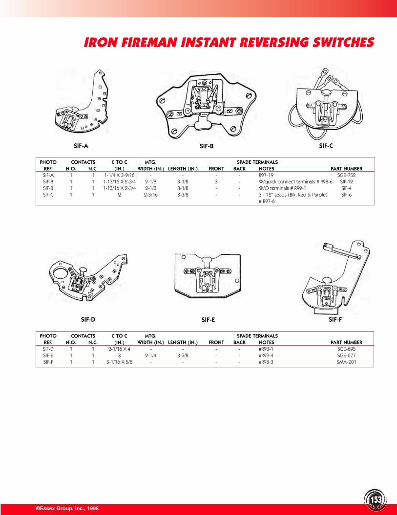
©Essex Group, Inc., 1998153
IRON FIREMAN INSTANT REVERSING SWITCHES
PHOTO CONTACTS C TO C MTG. SPADE TERMINALSREF. N.O. N.C. (IN.) WIDTH (IN.) LENGTH (IN.) FRONT BACK NOTES PART NUMBERSIF-A 1 1 1-1/4 X 3-9/16 - - - - R97-19 SGE-752SIF-B 1 1 1-13/16 X 2-3/4 2-1/8 3-1/8 3 - W/quick connect terminals # R98-6 SIF-12SIF-B 1 1 1-13/16 X 2-3/4 2-1/8 3-1/8 - - W/O terminals # R99-1 SIF-4SIF-C 1 1 2 2-3/16 3-3/8 - - 3 - 12" Leads (Blk, Red & Purple), SIF-6
# R97-6
PHOTO CONTACTS C TO C MTG. SPADE TERMINALSREF. N.O. N.C. (IN.) WIDTH (IN.) LENGTH (IN.) FRONT BACK NOTES PART NUMBERSIF-D 1 1 2-1/16 X 4 - - - - #R98-1 SGE-695SIF-E 1 1 3 2-1/4 3-3/8 - - #R99-4 SGE-677SIF-F 1 1 3-1/16 X 5/8 - - - - #R98-3 SMA-201
SIF-A SIF-B SIF-C
SIF-D SIF-E SIF-F
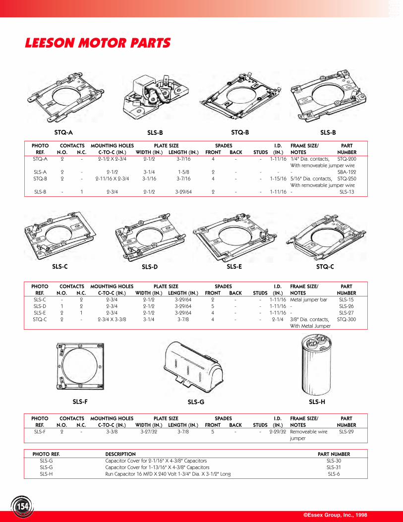
©Essex Group, Inc., 1998154
LEESON MOTOR PARTS
PHOTO CONTACTS MOUNTING HOLES PLATE SIZE SPADES I.D. FRAME SIZE/ PARTREF. N.O. N.C. C-TO-C (IN.) WIDTH (IN.) LENGTH (IN.) FRONT BACK STUDS (IN.) NOTES NUMBER
STQ-A 2 - 2-1/2 X 2-3/4 2-1/2 3-7/16 4 - - 1-11/16 1/4" Dia. contacts, STQ-200With removeable jumper wire
SLS-A 2 - 2-1/2 3-1/4 1-5/8 2 - - - - SBA-122STQ-B 2 - 2-11/16 X 2-3/4 3-1/16 3-7/16 4 - - 1-15/16 5/16" Dia. contacts, STQ-250
With removeable jumper wireSLS-B - 1 2-3/4 2-1/2 3-29/64 2 - - 1-11/16 - SLS-13
PHOTO CONTACTS MOUNTING HOLES PLATE SIZE SPADES I.D. FRAME SIZE/ PARTREF. N.O. N.C. C-TO-C (IN.) WIDTH (IN.) LENGTH (IN.) FRONT BACK STUDS (IN.) NOTES NUMBER
SLS-C - 2 2-3/4 2-1/2 3-29/64 2 - - 1-11/16 Metal jumper bar SLS-15SLS-D 1 2 2-3/4 2-1/2 3-29/64 5 - - 1-11/16 - SLS-26SLS-E 2 1 2-3/4 2-1/2 3-29/64 4 - - 1-11/16 - SLS-27STQ-C 2 - 2-3/4 X 3-3/8 3-1/4 3-7/8 4 - - 2-1/4 3/8" Dia. contacts, STQ-300
With Metal Jumper
PHOTO CONTACTS MOUNTING HOLES PLATE SIZE SPADES I.D. FRAME SIZE/ PARTREF. N.O. N.C. C-TO-C (IN.) WIDTH (IN.) LENGTH (IN.) FRONT BACK STUDS (IN.) NOTES NUMBERSLS-F 2 - 3-3/8 3-27/32 3-7/8 5 - - 2-29/32 Removeable wire SLS-29
jumper
PHOTO REF. DESCRIPTION PART NUMBERSLS-G Capacitor Cover for 2-1/16" X 4-3/8" Capacitors SLS-30SLS-G Capacitor Cover for 1-13/16" X 4-3/8" Capacitors SLS-31SLS-H Run Capacitor 16 MFD X 240 Volt 1-3/4" Dia. X 3-1/2" Long SLS-6
STQ-A SLS-B STQ-B SLS-B
SLS-C SLS-D SLS-E STQ-C
SLS-F SLS-G SLS-H
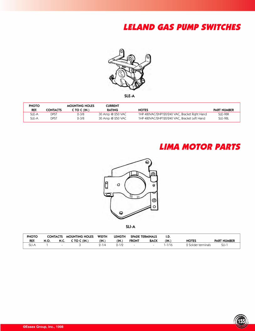
©Essex Group, Inc., 1998155
LELAND GAS PUMP SWITCHES
PHOTO MOUNTING HOLES CURRENTREF. CONTACTS C TO C (IN.) RATING NOTES PART NUMBER
SLE-A DPST 2-3/8 30 Amp @ 250 VAC 1HP 480VAC/2HP120/240 VAC, Bracket Right Hand SLE-98RSLE-A DPST 2-3/8 30 Amp @ 250 VAC 1HP 480VAC/2HP120/240 VAC, Bracket Left Hand SLE-98L
PHOTO CONTACTS MOUNTING HOLES WIDTH LENGTH SPADE TERMINALS I.D.REF. N.O. N.C. C TO C (IN.) (IN.) (IN.) FRONT BACK (IN.) NOTES PART NUMBERSLI-A 1 - 3 2-1/4 2-1/2 - - 1-1/16 2 Solder terminals SLI-1
LIMA MOTOR PARTS
SLE-A
SLI-A
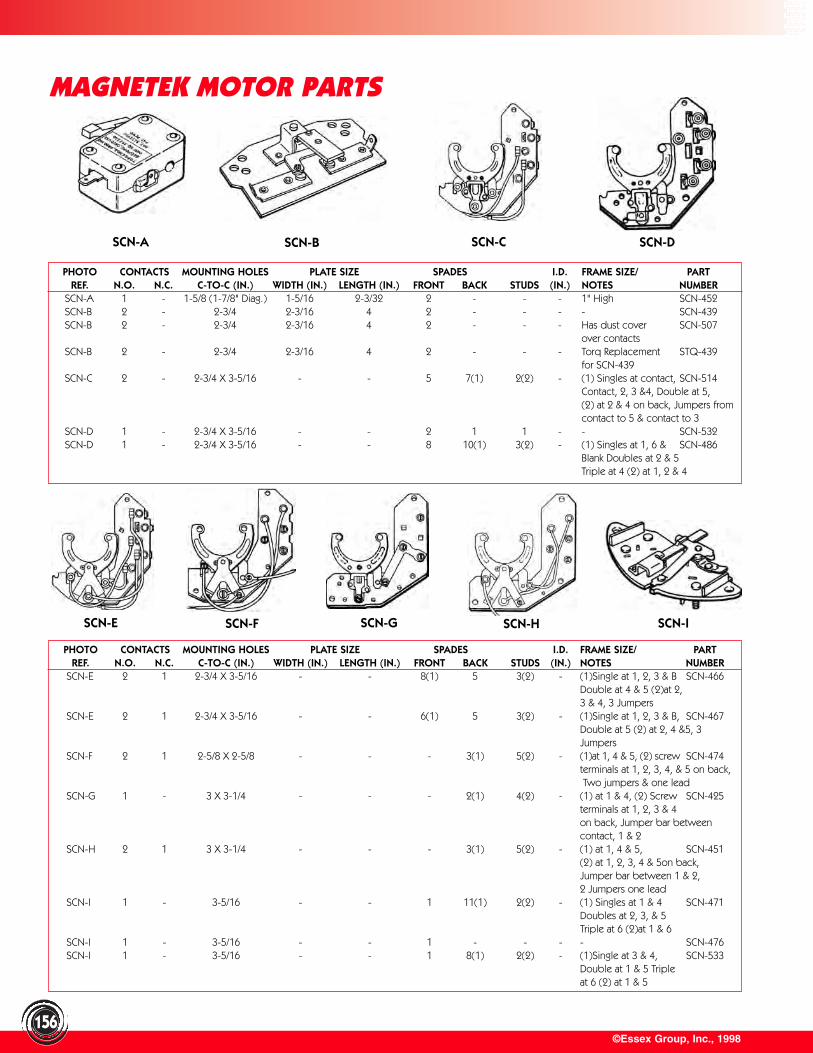
©Essex Group, Inc., 1998156
MAGNETEK MOTOR PARTS
PHOTO CONTACTS MOUNTING HOLES PLATE SIZE SPADES I.D. FRAME SIZE/ PARTREF. N.O. N.C. C-TO-C (IN.) WIDTH (IN.) LENGTH (IN.) FRONT BACK STUDS (IN.) NOTES NUMBER
SCN-E 2 1 2-3/4 X 3-5/16 - - 8(1) 5 3(2) - (1)Single at 1, 2, 3 & B SCN-466Double at 4 & 5 (2)at 2, 3 & 4, 3 Jumpers
SCN-E 2 1 2-3/4 X 3-5/16 - - 6(1) 5 3(2) - (1)Single at 1, 2, 3 & B, SCN-467Double at 5 (2) at 2, 4 &5, 3 Jumpers
SCN-F 2 1 2-5/8 X 2-5/8 - - - 3(1) 5(2) - (1)at 1, 4 & 5, (2) screw SCN-474terminals at 1, 2, 3, 4, & 5 on back,Two jumpers & one lead
SCN-G 1 - 3 X 3-1/4 - - - 2(1) 4(2) - (1) at 1 & 4, (2) Screw SCN-425terminals at 1, 2, 3 & 4 on back, Jumper bar between contact, 1 & 2
SCN-H 2 1 3 X 3-1/4 - - - 3(1) 5(2) - (1) at 1, 4 & 5, SCN-451(2) at 1, 2, 3, 4 & 5on back, Jumper bar between 1 & 2, 2 Jumpers one lead
SCN-I 1 - 3-5/16 - - 1 11(1) 2(2) - (1) Singles at 1 & 4 SCN-471Doubles at 2, 3, & 5 Triple at 6 (2)at 1 & 6
SCN-I 1 - 3-5/16 - - 1 - - - - SCN-476SCN-I 1 - 3-5/16 - - 1 8(1) 2(2) - (1)Single at 3 & 4, SCN-533
Double at 1 & 5 Tripleat 6 (2) at 1 & 5
PHOTO CONTACTS MOUNTING HOLES PLATE SIZE SPADES I.D. FRAME SIZE/ PARTREF. N.O. N.C. C-TO-C (IN.) WIDTH (IN.) LENGTH (IN.) FRONT BACK STUDS (IN.) NOTES NUMBER
SCN-A 1 - 1-5/8 (1-7/8" Diag.) 1-5/16 2-3/32 2 - - - 1" High SCN-452SCN-B 2 - 2-3/4 2-3/16 4 2 - - - - SCN-439SCN-B 2 - 2-3/4 2-3/16 4 2 - - - Has dust cover SCN-507
over contactsSCN-B 2 - 2-3/4 2-3/16 4 2 - - - Torq Replacement STQ-439
for SCN-439SCN-C 2 - 2-3/4 X 3-5/16 - - 5 7(1) 2(2) - (1) Singles at contact, SCN-514
Contact, 2, 3 &4, Double at 5,(2) at 2 & 4 on back, Jumpers from contact to 5 & contact to 3
SCN-D 1 - 2-3/4 X 3-5/16 - - 2 1 1 - - SCN-532SCN-D 1 - 2-3/4 X 3-5/16 - - 8 10(1) 3(2) - (1) Singles at 1, 6 & SCN-486
Blank Doubles at 2 & 5 Triple at 4 (2) at 1, 2 & 4
SCN-A SCN-B SCN-C SCN-D
SCN-E SCN-F SCN-G SCN-ISCN-H
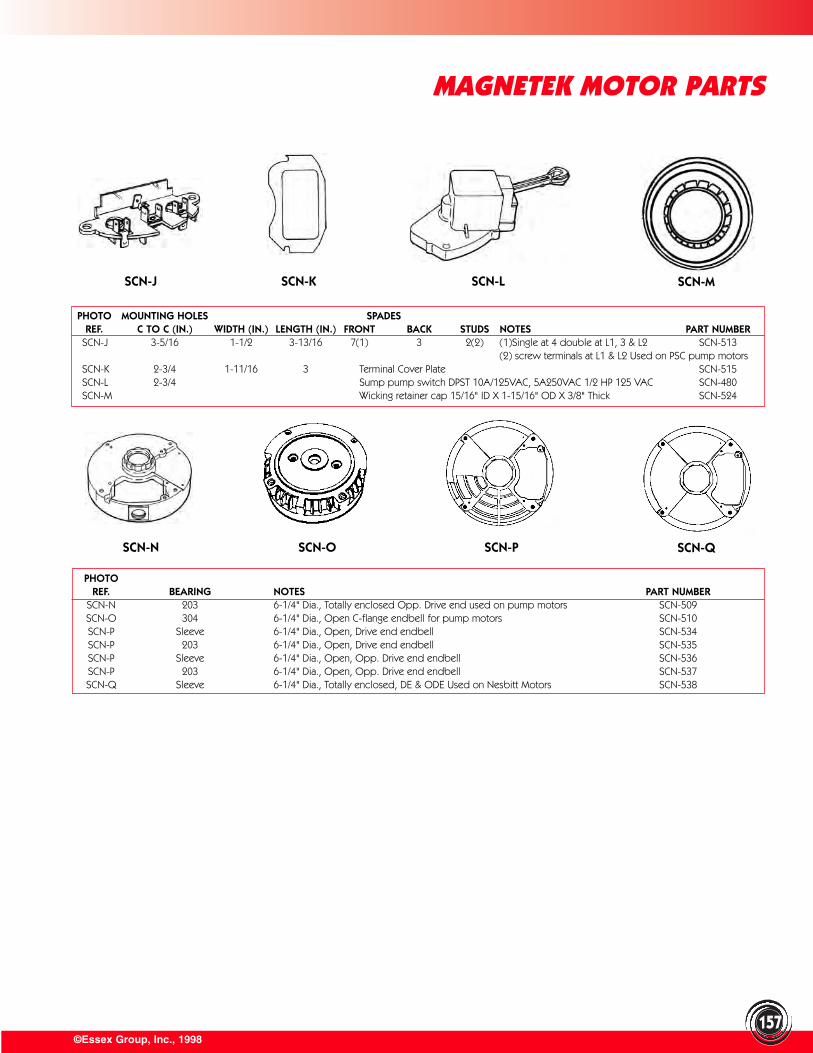
©Essex Group, Inc., 1998
MAGNETEK MOTOR PARTS
157
PHOTO MOUNTING HOLES SPADESREF. C TO C (IN.) WIDTH (IN.) LENGTH (IN.) FRONT BACK STUDS NOTES PART NUMBER
SCN-J 3-5/16 1-1/2 3-13/16 7(1) 3 2(2) (1)Single at 4 double at L1, 3 & L2 SCN-513(2) screw terminals at L1 & L2 Used on PSC pump motors
SCN-K 2-3/4 1-11/16 3 Terminal Cover Plate SCN-515SCN-L 2-3/4 Sump pump switch DPST 10A/125VAC, 5A250VAC 1/2 HP 125 VAC SCN-480SCN-M Wicking retainer cap 15/16" ID X 1-15/16" OD X 3/8" Thick SCN-524
PHOTOREF. BEARING NOTES PART NUMBER
SCN-N 203 6-1/4" Dia., Totally enclosed Opp. Drive end used on pump motors SCN-509SCN-O 304 6-1/4" Dia., Open C-flange endbell for pump motors SCN-510SCN-P Sleeve 6-1/4" Dia., Open, Drive end endbell SCN-534SCN-P 203 6-1/4" Dia., Open, Drive end endbell SCN-535SCN-P Sleeve 6-1/4" Dia., Open, Opp. Drive end endbell SCN-536SCN-P 203 6-1/4" Dia., Open, Opp. Drive end endbell SCN-537SCN-Q Sleeve 6-1/4" Dia., Totally enclosed, DE & ODE Used on Nesbitt Motors SCN-538
SCN-J SCN-K SCN-L SCN-M
SCN-N SCN-O SCN-P SCN-Q
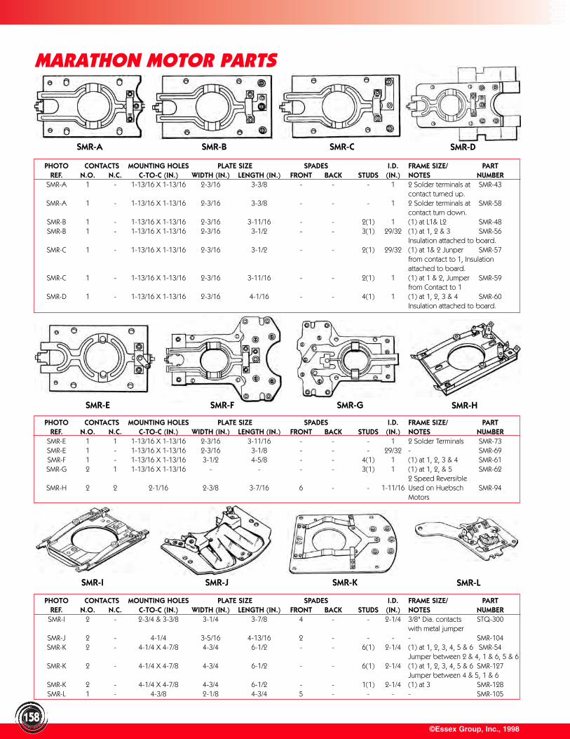
PHOTO CONTACTS MOUNTING HOLES PLATE SIZE SPADES I.D. FRAME SIZE/ PARTREF. N.O. N.C. C-TO-C (IN.) WIDTH (IN.) LENGTH (IN.) FRONT BACK STUDS (IN.) NOTES NUMBER
SMR-I 2 - 2-3/4 & 3-3/8 3-1/4 3-7/8 4 - - 2-1/4 3/8" Dia. contacts STQ-300with metal jumper
SMR-J 2 - 4-1/4 3-5/16 4-13/16 2 - - - - SMR-104SMR-K 2 - 4-1/4 X 4-7/8 4-3/4 6-1/2 - - 6(1) 2-1/4 (1) at 1, 2, 3, 4, 5 & 6 SMR-54
Jumper between 2 & 4, 1 & 6, 5 & 6SMR-K 2 - 4-1/4 X 4-7/8 4-3/4 6-1/2 - - 6(1) 2-1/4 (1) at 1, 2, 3, 4, 5 & 6 SMR-127
Jumper between 4 & 5, 1 & 6SMR-K 2 - 4-1/4 X 4-7/8 4-3/4 6-1/2 - - 1(1) 2-1/4 (1) at 3 SMR-128SMR-L 1 - 4-3/8 2-1/8 4-3/4 5 - - - - SMR-105
©Essex Group, Inc., 1998
MARATHON MOTOR PARTS
158
PHOTO CONTACTS MOUNTING HOLES PLATE SIZE SPADES I.D. FRAME SIZE/ PARTREF. N.O. N.C. C-TO-C (IN.) WIDTH (IN.) LENGTH (IN.) FRONT BACK STUDS (IN.) NOTES NUMBER
SMR-E 1 1 1-13/16 X 1-13/16 2-3/16 3-11/16 - - - 1 2 Solder Terminals SMR-73SMR-E 1 - 1-13/16 X 1-13/16 2-3/16 3-1/8 - - - 29/32 - SMR-69SMR-F 1 - 1-13/16 X 1-13/16 3-1/2 4-5/8 - - 4(1) 1 (1) at 1, 2, 3 & 4 SMR-61SMR-G 2 1 1-13/16 X 1-13/16 - - - - 3(1) 1 (1) at 1, 2, & 5 SMR-62
2 Speed ReversibleSMR-H 2 2 2-1/16 2-3/8 3-7/16 6 - - 1-11/16 Used on Huebsch SMR-94
Motors
PHOTO CONTACTS MOUNTING HOLES PLATE SIZE SPADES I.D. FRAME SIZE/ PARTREF. N.O. N.C. C-TO-C (IN.) WIDTH (IN.) LENGTH (IN.) FRONT BACK STUDS (IN.) NOTES NUMBER
SMR-A 1 - 1-13/16 X 1-13/16 2-3/16 3-3/8 - - - 1 2 Solder terminals at SMR-43contact turned up.
SMR-A 1 - 1-13/16 X 1-13/16 2-3/16 3-3/8 - - - 1 2 Solder terminals at SMR-58contact turn down.
SMR-B 1 - 1-13/16 X 1-13/16 2-3/16 3-11/16 - - 2(1) 1 (1) at L1& L2 SMR-48SMR-B 1 - 1-13/16 X 1-13/16 2-3/16 3-1/2 - - 3(1) 29/32 (1) at 1, 2 & 3 SMR-56
Insulation attached to board.SMR-C 1 - 1-13/16 X 1-13/16 2-3/16 3-1/2 - - 2(1) 29/32 (1) at 1& 2 Junper SMR-57
from contact to 1, Insulation attached to board.
SMR-C 1 - 1-13/16 X 1-13/16 2-3/16 3-11/16 - - 2(1) 1 (1) at 1 & 2, Jumper SMR-59from Contact to 1
SMR-D 1 - 1-13/16 X 1-13/16 2-3/16 4-1/16 - - 4(1) 1 (1) at 1, 2, 3 & 4 SMR-60Insulation attached to board.
SMR-A SMR-B SMR-C SMR-D
SMR-E SMR-F SMR-G SMR-H
SMR-I SMR-J SMR-K SMR-L
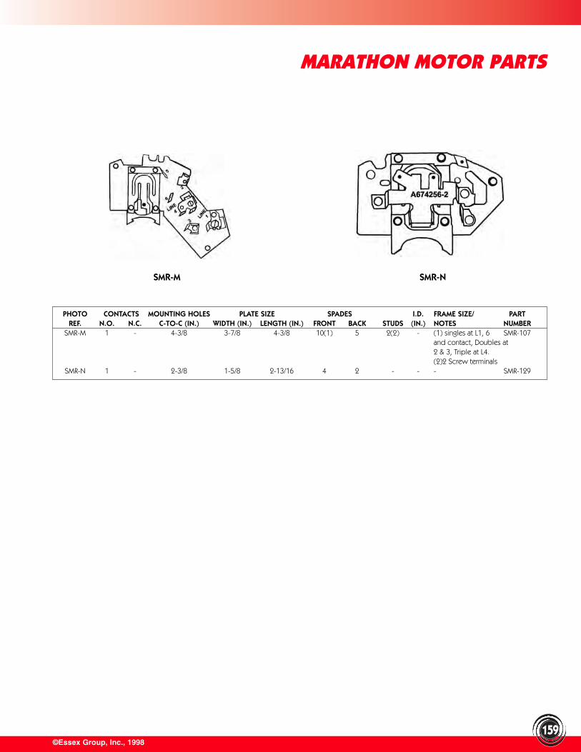
©Essex Group, Inc., 1998
MARATHON MOTOR PARTS
159
PHOTO CONTACTS MOUNTING HOLES PLATE SIZE SPADES I.D. FRAME SIZE/ PARTREF. N.O. N.C. C-TO-C (IN.) WIDTH (IN.) LENGTH (IN.) FRONT BACK STUDS (IN.) NOTES NUMBER
SMR-M 1 - 4-3/8 3-7/8 4-3/8 10(1) 5 2(2) - (1) singles at L1, 6 SMR-107and contact, Doubles at 2 & 3, Triple at L4. (2)2 Screw terminals
SMR-N 1 - 2-3/8 1-5/8 2-13/16 4 2 - - - SMR-129
SMR-M SMR-N
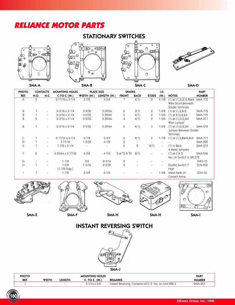
©Essex Group, Inc., 1998160
RELIANCE MOTOR PARTS
PHOTO CONTACTS MOUNTING HOLES PLATE SIZE SPADES I.D. PARTREF. N.O. N.C. C-TO-C (IN.) WIDTH (IN.) LENGTH (IN.) FRONT BACK STUDS (IN.) NOTES NUMBERA 2 - 2-11/16 x 3-1/4 3-7/8 3-3/4 7 4(1) 2 1-7/8 (1) at L1,3,L2 & Blank SMA-170
Wire Shunt Between Solder Terminals
B 1 - 2-3/16 x 3-1/4 3-9/32 3-39/64 6 3(1) 2 1-5/8 (1) at L1,3,&L2 SMA-172B 1 - 2-3/16 x 3-1/4 3-9/32 3-39/64 6 4(1) 2 1-5/8 (1) at 2,3,L2,&4 SMA-175B 2 - 2-3/16 x 3-1/4 3-9/32 3-39/64 4 4(1) 2 1-5/8 (1) at L1,3,L2,&4 SMA-217
Wire JumperB 1 - 2-3/16 x 3-1/4 3-9/32 3-39/64 5 4(1) 3 1-5/8 (1) at L1,2,L2,&4 SMA-218
Jumper Between SolderTerminals
C 1 - 2-11/16 x 3-1/4 3-7/8 3-3/4 6 4(1) 2 1-7/8 (1) at L1,3,Blank,&L2 SMA-171D 1 - 3-11/16 1-3/32 4-1/8 2 - - - - SMA-220E 1 - 1-7/8 x 3-1/4 - - 6 8 2(1) - (1) in Back SMA-219
4 Metal JumpersF 2 - 3-55/64 x 3-17/32 4-3/8 4-1/2 2 at T5 & T9 2(1) - - (1) at C & D SMA-246
No. on Switch is 36C072G - - 1-7/8 3/4 2-3/16 2 - - - SHO-15H 1 - 1-5/8 1-5/16 2-3/32 2 - - - Dustite Switch 1” SCN-452
(1-7/8 Diag.) HighI 1 - 1-7/8 2-3/8 2-1/2 - - - 1-3/8 Metal Pads on SOH-55
Contact Arma
PHOTO MOUNTING HOLES PARTREF. WIDTH LENGTH C. TO C. (IN.) REMARKS NUMBER
J - - 3-1/16 x 5/8 Instant Reversing Contacts N/O: 2 No. on Unit R98-3 SMA-201
SMA-A SMA-B SMA-C SMA-D
STATIONARY SWITCHES
SMA-J
INSTANT REVERSING SWITCH
SMA-E SMA-F SMA-H SMA-ISMA-H
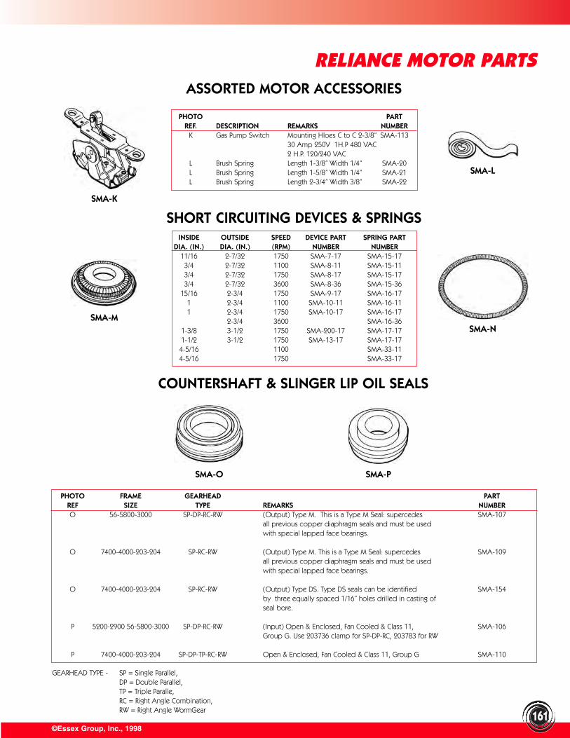
©Essex Group, Inc., 1998
RELIANCE MOTOR PARTS
161
ASSORTED MOTOR ACCESSORIES
SHORT CIRCUITING DEVICES & SPRINGS
COUNTERSHAFT & SLINGER LIP OIL SEALS
PHOTO PARTREF. DESCRIPTION REMARKS NUMBER
K Gas Pump Switch Mounting Hloes C to C 2-3/8” SMA-11330 Amp 250V 1H.P 480 VAC2 H.P. 120/240 VAC
L Brush Spring Length 1-3/8” Width 1/4” SMA-20L Brush Spring Length 1-5/8” Width 1/4” SMA-21L Brush Spring Length 2-3/4” Width 3/8” SMA-22
INSIDE OUTSIDE SPEED DEVICE PART SPRING PARTDIA. (IN.) DIA. (IN.) (RPM) NUMBER NUMBER
11/16 2-7/32 1750 SMA-7-17 SMA-15-173/4 2-7/32 1100 SMA-8-11 SMA-15-113/4 2-7/32 1750 SMA-8-17 SMA-15-173/4 2-7/32 3600 SMA-8-36 SMA-15-36
15/16 2-3/4 1750 SMA-9-17 SMA-16-171 2-3/4 1100 SMA-10-11 SMA-16-111 2-3/4 1750 SMA-10-17 SMA-16-17
2-3/4 3600 SMA-16-361-3/8 3-1/2 1750 SMA-200-17 SMA-17-171-1/2 3-1/2 1750 SMA-13-17 SMA-17-174-5/16 1100 SMA-33-114-5/16 1750 SMA-33-17
PHOTO FRAME GEARHEAD PARTREF SIZE TYPE REMARKS NUMBERO 56-5800-3000 SP-DP-RC-RW (Output) Type M. This is a Type M Seal: supercedes SMA-107
all previous copper diaphragm seals and must be usedwith special lapped face bearings.
O 7400-4000-203-204 SP-RC-RW (Output) Type M. This is a Type M Seal: supercedes SMA-109all previous copper diaphragm seals and must be usedwith special lapped face bearings.
O 7400-4000-203-204 SP-RC-RW (Output) Type DS. Type DS seals can be identified SMA-154by three equally spaced 1/16” holes drilled in casting ofseal bore.
P 5200-2900 56-5800-3000 SP-DP-RC-RW (Input) Open & Enclosed, Fan Cooled & Class 11, SMA-106Group G. Use 203736 clamp for SP-DP-RC, 203783 for RW
P 7400-4000-203-204 SP-DP-TP-RC-RW Open & Enclosed, Fan Cooled & Class 11, Group G SMA-110
GEARHEAD TYPE - SP = Single Parallel, DP = Double Parallel,TP = Triple Paralle,RC = Right Angle Combination, RW = Right Angle WormGear
SMA-K
SMA-M
SMA-L
SMA-N
SMA-O SMA-P
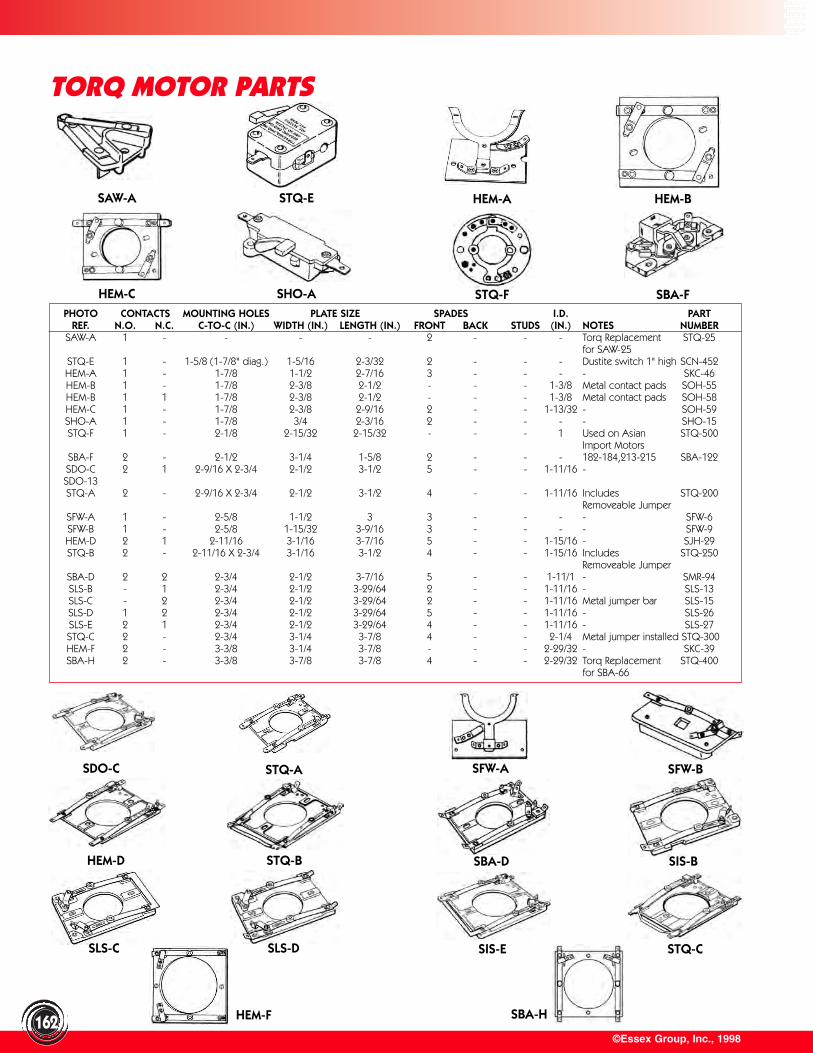
©Essex Group, Inc., 1998162
TORQ MOTOR PARTS
SAW-A STQ-E HEM-A HEM-B
HEM-C SHO-A STQ-F SBA-FPHOTO CONTACTS MOUNTING HOLES PLATE SIZE SPADES I.D. PART
REF. N.O. N.C. C-TO-C (IN.) WIDTH (IN.) LENGTH (IN.) FRONT BACK STUDS (IN.) NOTES NUMBERSAW-A 1 - - - - 2 - - - Torq Replacement STQ-25
for SAW-25STQ-E 1 - 1-5/8 (1-7/8" diag.) 1-5/16 2-3/32 2 - - - Dustite switch 1" high SCN-452HEM-A 1 - 1-7/8 1-1/2 2-7/16 3 - - - - SKC-46HEM-B 1 - 1-7/8 2-3/8 2-1/2 - - - 1-3/8 Metal contact pads SOH-55HEM-B 1 1 1-7/8 2-3/8 2-1/2 - - - 1-3/8 Metal contact pads SOH-58HEM-C 1 - 1-7/8 2-3/8 2-9/16 2 - - 1-13/32 - SOH-59SHO-A 1 - 1-7/8 3/4 2-3/16 2 - - - - SHO-15STQ-F 1 - 2-1/8 2-15/32 2-15/32 - - - 1 Used on Asian STQ-500
Import MotorsSBA-F 2 - 2-1/2 3-1/4 1-5/8 2 - - - 182-184,213-215 SBA-122SDO-C 2 1 2-9/16 X 2-3/4 2-1/2 3-1/2 5 - - 1-11/16 -SDO-13STQ-A 2 - 2-9/16 X 2-3/4 2-1/2 3-1/2 4 - - 1-11/16 Includes STQ-200
Removeable JumperSFW-A 1 - 2-5/8 1-1/2 3 3 - - - - SFW-6SFW-B 1 - 2-5/8 1-15/32 3-9/16 3 - - - - SFW-9HEM-D 2 1 2-11/16 3-1/16 3-7/16 5 - - 1-15/16 - SJH-29STQ-B 2 - 2-11/16 X 2-3/4 3-1/16 3-1/2 4 - - 1-15/16 Includes STQ-250
Removeable JumperSBA-D 2 2 2-3/4 2-1/2 3-7/16 5 - - 1-11/1 - SMR-94SLS-B - 1 2-3/4 2-1/2 3-29/64 2 - - 1-11/16 - SLS-13SLS-C - 2 2-3/4 2-1/2 3-29/64 2 - - 1-11/16 Metal jumper bar SLS-15SLS-D 1 2 2-3/4 2-1/2 3-29/64 5 - - 1-11/16 - SLS-26SLS-E 2 1 2-3/4 2-1/2 3-29/64 4 - - 1-11/16 - SLS-27STQ-C 2 - 2-3/4 3-1/4 3-7/8 4 - - 2-1/4 Metal jumper installed STQ-300HEM-F 2 - 3-3/8 3-1/4 3-7/8 - - - 2-29/32 - SKC-39SBA-H 2 - 3-3/8 3-7/8 3-7/8 4 - - 2-29/32 Torq Replacement STQ-400
for SBA-66
SDO-C STQ-A SFW-A SFW-B
HEM-D STQ-B SBA-D SIS-B
SLS-C SLS-D SIS-E STQ-C
HEM-F SBA-H
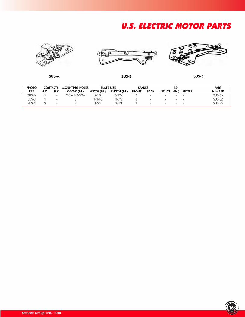
©Essex Group, Inc., 1998
U.S. ELECTRIC MOTOR PARTS
163
PHOTO CONTACTS MOUNTING HOLES PLATE SIZE SPADES I.D. PARTREF. N.O. N.C. C-TO-C (IN.) WIDTH (IN.) LENGTH (IN.) FRONT BACK STUDS (IN.) NOTES NUMBER
SUS-A 1 - 2-3/4 & 3-3/16 2-1/4 3-9/16 2 - - - - SUS-36SUS-B 1 - 3 1-3/16 3-7/8 2 - - - - SUS-32SUS-C 2 - 3 1-5/8 3-3/4 2 - - - - SUS-35
SUS-A SUS-B SUS-C
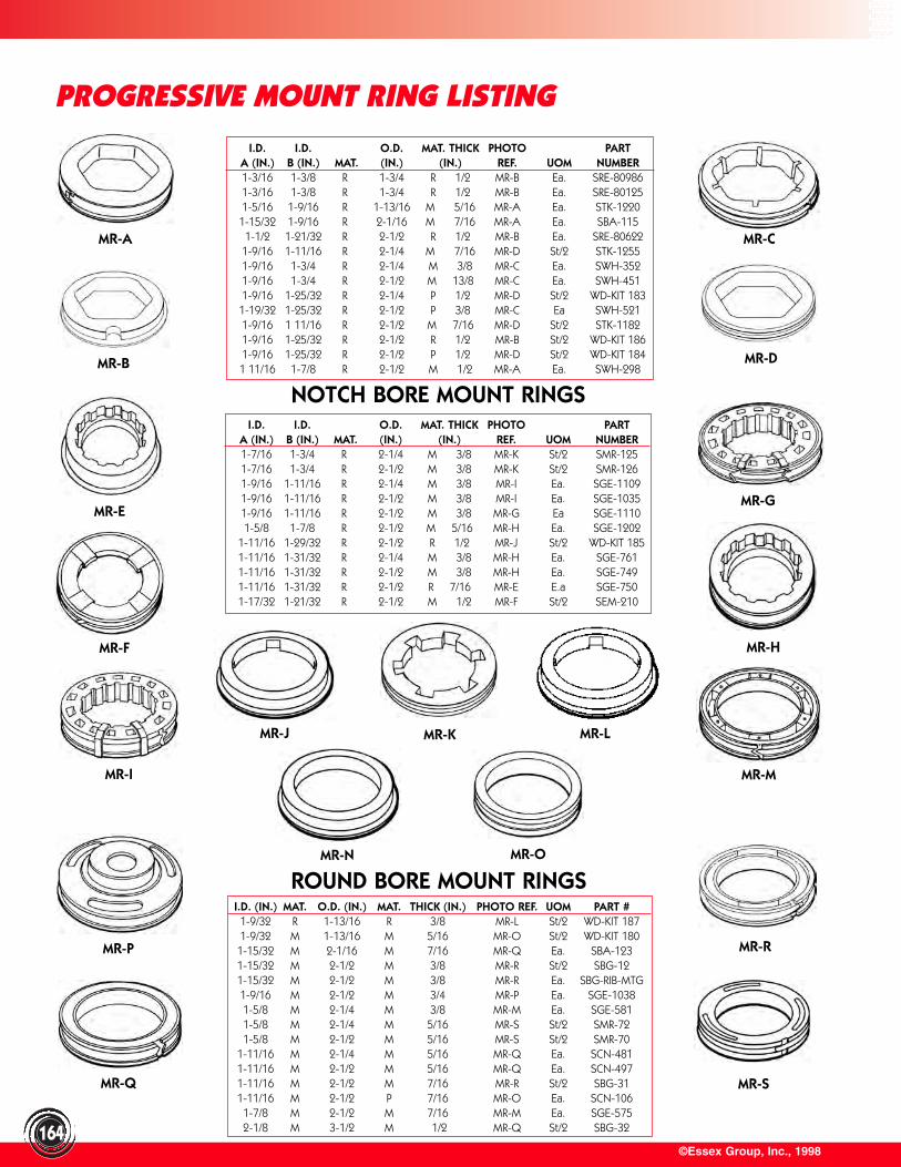
MR-A MR-C
©Essex Group, Inc., 1998164
PROGRESSIVE MOUNT RING LISTING
NOTCH BORE MOUNT RINGS
I.D. I.D. O.D. MAT. THICK PHOTO PARTA (IN.) B (IN.) MAT. (IN.) (IN.) REF. UOM NUMBER1-3/16 1-3/8 R 1-3/4 R 1/2 MR-B Ea. SRE-809861-3/16 1-3/8 R 1-3/4 R 1/2 MR-B Ea. SRE-801251-5/16 1-9/16 R 1-13/16 M 5/16 MR-A Ea. STK-12201-15/32 1-9/16 R 2-1/16 M 7/16 MR-A Ea. SBA-1151-1/2 1-21/32 R 2-1/2 R 1/2 MR-B Ea. SRE-806221-9/16 1-11/16 R 2-1/4 M 7/16 MR-D St/2 STK-12551-9/16 1-3/4 R 2-1/4 M 3/8 MR-C Ea. SWH-3521-9/16 1-3/4 R 2-1/2 M 13/8 MR-C Ea. SWH-4511-9/16 1-25/32 R 2-1/4 P 1/2 MR-D St/2 WD-KIT 1831-19/32 1-25/32 R 2-1/2 P 3/8 MR-C Ea SWH-5211-9/16 1 11/16 R 2-1/2 M 7/16 MR-D St/2 STK-11821-9/16 1-25/32 R 2-1/2 R 1/2 MR-B St/2 WD-KIT 1861-9/16 1-25/32 R 2-1/2 P 1/2 MR-D St/2 WD-KIT 1841 11/16 1-7/8 R 2-1/2 M 1/2 MR-A Ea. SWH-298
I.D. I.D. O.D. MAT. THICK PHOTO PARTA (IN.) B (IN.) MAT. (IN.) (IN.) REF. UOM NUMBER1-7/16 1-3/4 R 2-1/4 M 3/8 MR-K St/2 SMR-1251-7/16 1-3/4 R 2-1/2 M 3/8 MR-K St/2 SMR-1261-9/16 1-11/16 R 2-1/4 M 3/8 MR-I Ea. SGE-11091-9/16 1-11/16 R 2-1/2 M 3/8 MR-I Ea. SGE-10351-9/16 1-11/16 R 2-1/2 M 3/8 MR-G Ea SGE-11101-5/8 1-7/8 R 2-1/2 M 5/16 MR-H Ea. SGE-1202
1-11/16 1-29/32 R 2-1/2 R 1/2 MR-J St/2 WD-KIT 1851-11/16 1-31/32 R 2-1/4 M 3/8 MR-H Ea. SGE-7611-11/16 1-31/32 R 2-1/2 M 3/8 MR-H Ea. SGE-7491-11/16 1-31/32 R 2-1/2 R 7/16 MR-E E.a SGE-7501-17/32 1-21/32 R 2-1/2 M 1/2 MR-F St/2 SEM-210
I.D. (IN.) MAT. O.D. (IN.) MAT. THICK (IN.) PHOTO REF. UOM PART #1-9/32 R 1-13/16 R 3/8 MR-L St/2 WD-KIT 1871-9/32 M 1-13/16 M 5/16 MR-O St/2 WD-KIT 1801-15/32 M 2-1/16 M 7/16 MR-Q Ea. SBA-1231-15/32 M 2-1/2 M 3/8 MR-R St/2 SBG-121-15/32 M 2-1/2 M 3/8 MR-R Ea. SBG-RIB-MTG1-9/16 M 2-1/2 M 3/4 MR-P Ea. SGE-10381-5/8 M 2-1/4 M 3/8 MR-M Ea. SGE-5811-5/8 M 2-1/4 M 5/16 MR-S St/2 SMR-721-5/8 M 2-1/2 M 5/16 MR-S St/2 SMR-70
1-11/16 M 2-1/4 M 5/16 MR-Q Ea. SCN-4811-11/16 M 2-1/2 M 5/16 MR-Q Ea. SCN-4971-11/16 M 2-1/2 M 7/16 MR-R St/2 SBG-311-11/16 M 2-1/2 P 7/16 MR-O Ea. SCN-106
1-7/8 M 2-1/2 M 7/16 MR-M Ea. SGE-5752-1/8 M 3-1/2 M 1/2 MR-Q St/2 SBG-32
MR-B MR-D
MR-E
MR-H
MR-G
MR-I
MR-K
MR-F
MR-J MR-L
MR-M
MR-N MR-O
MR-P
MR-Q
MR-R
MR-S
ROUND BORE MOUNT RINGS
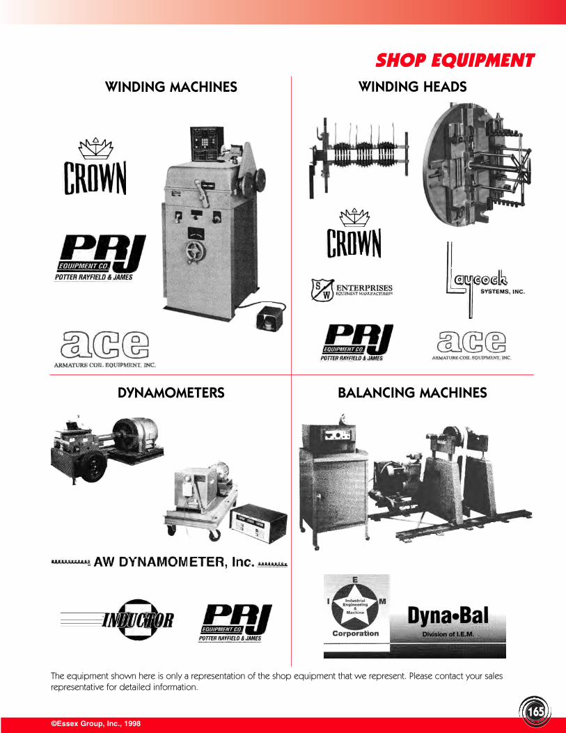
165©Essex Group, Inc., 1998
SHOP EQUIPMENTWINDING MACHINES WINDING HEADS
DYNAMOMETERS BALANCING MACHINES
The equipment shown here is only a representation of the shop equipment that we represent. Please contact your sales representative for detailed information.
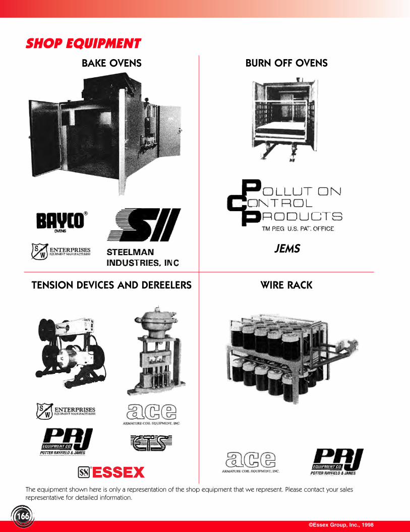
©Essex Group, Inc., 1998166
SHOP EQUIPMENTBAKE OVENS BURN OFF OVENS
TENSION DEVICES AND DEREELERS WIRE RACK
®
The equipment shown here is only a representation of the shop equipment that we represent. Please contact your sales representative for detailed information.
JEMS

©Essex Group, Inc., 1998
SHOP EQUIPMENT
167
PULLERS COIL CUT-OFF
SPRAY BOOTHS SAND BLASTERS
The equipment shown here is only a representation of the shop equipment that we represent. Please contact your sales representative for detailed information.
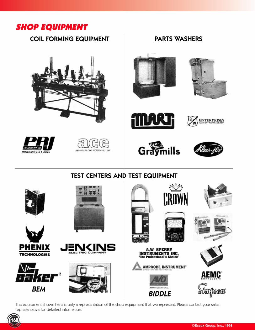
©Essex Group, Inc., 1998168
SHOP EQUIPMENTCOIL FORMING EQUIPMENT PARTS WASHERS
TEST CENTERS AND TEST EQUIPMENT
BIDDLEBEM
The equipment shown here is only a representation of the shop equipment that we represent. Please contact your sales representative for detailed information.
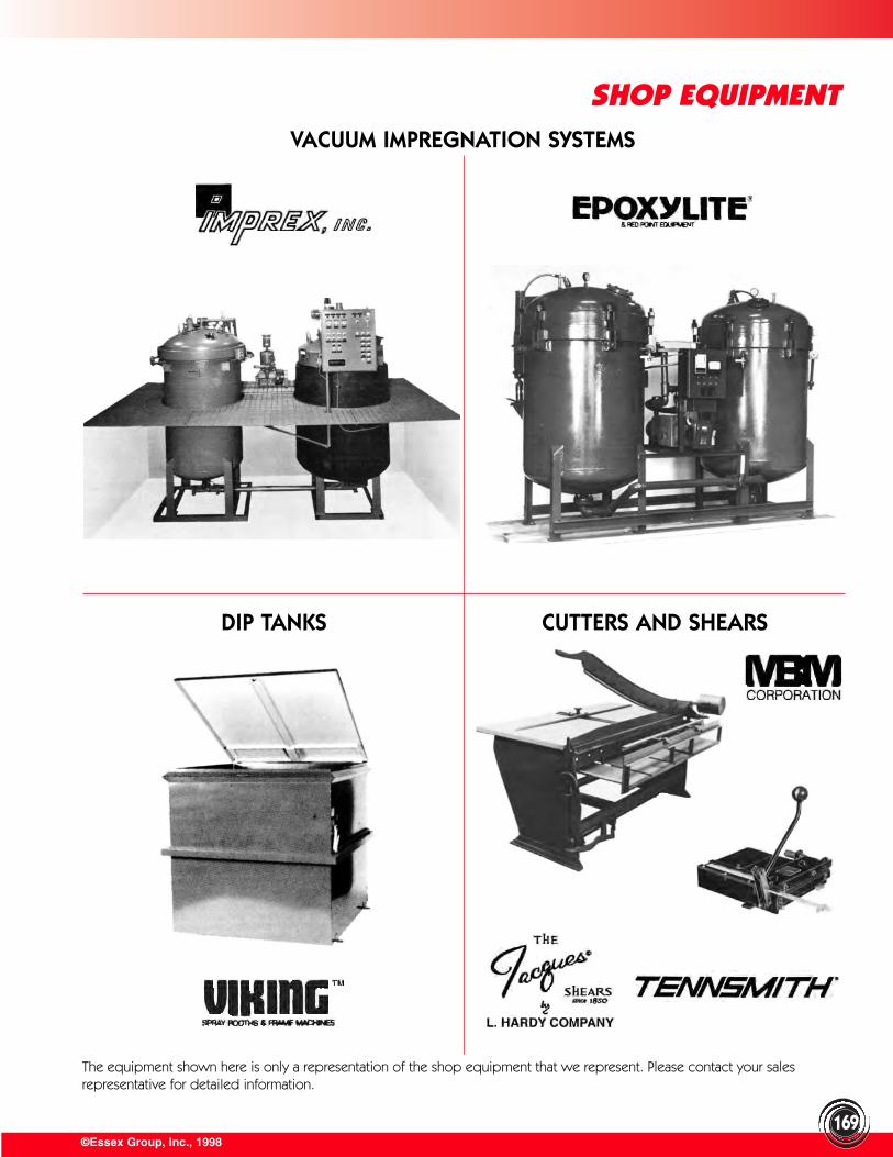
©Essex Group, Inc., 1998169
SHOP EQUIPMENTVACUUM IMPREGNATION SYSTEMS
DIP TANKS CUTTERS AND SHEARS
The equipment shown here is only a representation of the shop equipment that we represent. Please contact your sales representative for detailed information.
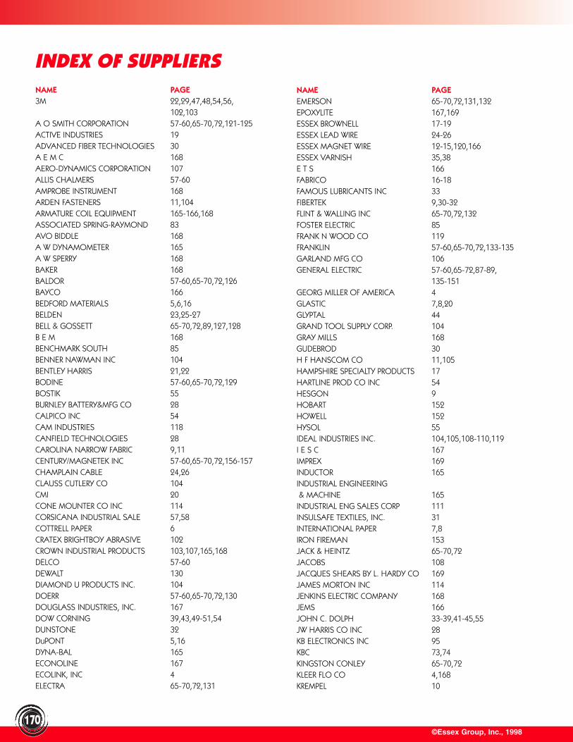
©Essex Group, Inc., 1998170
INDEX OF SUPPLIERSNAME PAGE3M 22,29,47,48,54,56,
102,103A O SMITH CORPORATION 57-60,65-70,72,121-125ACTIVE INDUSTRIES 19ADVANCED FIBER TECHNOLOGIES 30A E M C 168AERO-DYNAMICS CORPORATION 107ALLIS CHALMERS 57-60AMPROBE INSTRUMENT 168ARDEN FASTENERS 11,104ARMATURE COIL EQUIPMENT 165-166,168ASSOCIATED SPRING-RAYMOND 83AVO BIDDLE 168A W DYNAMOMETER 165A W SPERRY 168BAKER 168BALDOR 57-60,65-70,72,126BAYCO 166BEDFORD MATERIALS 5,6,16BELDEN 23,25-27BELL & GOSSETT 65-70,72,89,127,128B E M 168BENCHMARK SOUTH 85BENNER NAWMAN INC 104BENTLEY HARRIS 21,22BODINE 57-60,65-70,72,129BOSTIK 55BURNLEY BATTERY&MFG CO 28CALPICO INC 54CAM INDUSTRIES 118CANFIELD TECHNOLOGIES 28CAROLINA NARROW FABRIC 9,11CENTURY/MAGNETEK INC 57-60,65-70,72,156-157CHAMPLAIN CABLE 24,26CLAUSS CUTLERY CO 104CMI 20CONE MOUNTER CO INC 114CORSICANA INDUSTRIAL SALE 57,58COTTRELL PAPER 6CRATEX BRIGHTBOY ABRASIVE 102CROWN INDUSTRIAL PRODUCTS 103,107,165,168DELCO 57-60DEWALT 130DIAMOND U PRODUCTS INC. 104DOERR 57-60,65-70,72,130DOUGLASS INDUSTRIES, INC. 167DOW CORNING 39,43,49-51,54DUNSTONE 32DuPONT 5,16DYNA-BAL 165ECONOLINE 167ECOLINK, INC 4ELECTRA 65-70,72,131
NAME PAGEEMERSON 65-70,72,131,132EPOXYLITE 167,169ESSEX BROWNELL 17-19ESSEX LEAD WIRE 24-26ESSEX MAGNET WIRE 12-15,120,166ESSEX VARNISH 35,38E T S 166FABRICO 16-18FAMOUS LUBRICANTS INC 33FIBERTEK 9,30-32FLINT & WALLING INC 65-70,72,132FOSTER ELECTRIC 85FRANK N WOOD CO 119FRANKLIN 57-60,65-70,72,133-135GARLAND MFG CO 106GENERAL ELECTRIC 57-60,65-72,87-89,
135-151GEORG MILLER OF AMERICA 4GLASTIC 7,8,20GLYPTAL 44GRAND TOOL SUPPLY CORP. 104GRAY MILLS 168GUDEBROD 30H F HANSCOM CO 11,105HAMPSHIRE SPECIALTY PRODUCTS 17HARTLINE PROD CO INC 54HESGON 9HOBART 152HOWELL 152HYSOL 55IDEAL INDUSTRIES INC. 104,105,108-110,119I E S C 167IMPREX 169INDUCTOR 165INDUSTRIAL ENGINEERING& MACHINE 165
INDUSTRIAL ENG SALES CORP 111INSULSAFE TEXTILES, INC. 31INTERNATIONAL PAPER 7,8IRON FIREMAN 153JACK & HEINTZ 65-70,72JACOBS 108JACQUES SHEARS BY L. HARDY CO 169JAMES MORTON INC 114JENKINS ELECTRIC COMPANY 168JEMS 166JOHN C. DOLPH 33-39,41-45,55JW HARRIS CO INC 28KB ELECTRONICS INC 95KBC 73,74KINGSTON CONLEY 65-70,72KLEER FLO CO 4,168KREMPEL 10
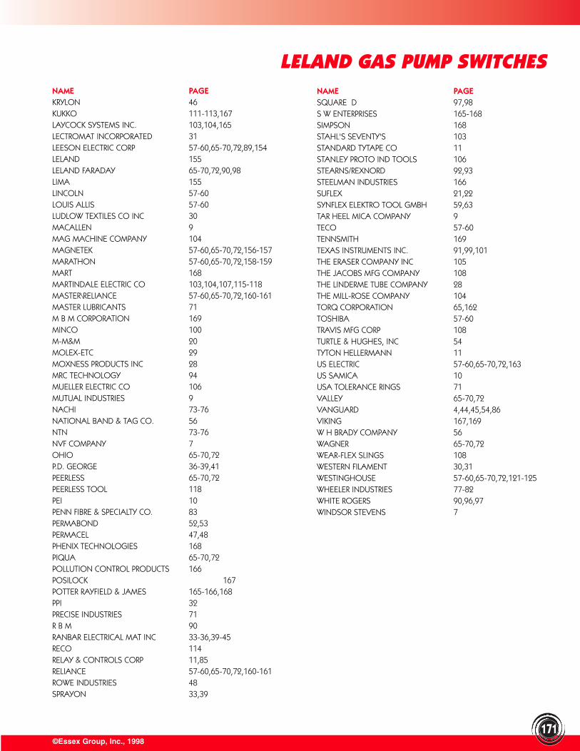
©Essex Group, Inc., 1998171
LELAND GAS PUMP SWITCHESNAME PAGEKRYLON 46KUKKO 111-113,167LAYCOCK SYSTEMS INC. 103,104,165LECTROMAT INCORPORATED 31LEESON ELECTRIC CORP 57-60,65-70,72,89,154LELAND 155LELAND FARADAY 65-70,72,90,98LIMA 155LINCOLN 57-60LOUIS ALLIS 57-60LUDLOW TEXTILES CO INC 30MACALLEN 9MAG MACHINE COMPANY 104MAGNETEK 57-60,65-70,72,156-157MARATHON 57-60,65-70,72,158-159MART 168MARTINDALE ELECTRIC CO 103,104,107,115-118MASTER\RELIANCE 57-60,65-70,72,160-161MASTER LUBRICANTS 71M B M CORPORATION 169MINCO 100M-M&M 20MOLEX-ETC 29MOXNESS PRODUCTS INC 28MRC TECHNOLOGY 94MUELLER ELECTRIC CO 106MUTUAL INDUSTRIES 9NACHI 73-76NATIONAL BAND & TAG CO. 56NTN 73-76NVF COMPANY 7OHIO 65-70,72P.D. GEORGE 36-39,41PEERLESS 65-70,72PEERLESS TOOL 118PEI 10PENN FIBRE & SPECIALTY CO. 83PERMABOND 52,53PERMACEL 47,48PHENIX TECHNOLOGIES 168PIQUA 65-70,72POLLUTION CONTROL PRODUCTS 166POSILOCK 167POTTER RAYFIELD & JAMES 165-166,168PPI 32PRECISE INDUSTRIES 71R B M 90RANBAR ELECTRICAL MAT INC 33-36,39-45RECO 114RELAY & CONTROLS CORP 11,85RELIANCE 57-60,65-70,72,160-161ROWE INDUSTRIES 48SPRAYON 33,39
NAME PAGESQUARE D 97,98S W ENTERPRISES 165-168SIMPSON 168STAHL'S SEVENTY'S 103STANDARD TYTAPE CO 11STANLEY PROTO IND TOOLS 106STEARNS/REXNORD 92,93STEELMAN INDUSTRIES 166SUFLEX 21,22SYNFLEX ELEKTRO TOOL GMBH 59,63TAR HEEL MICA COMPANY 9TECO 57-60TENNSMITH 169TEXAS INSTRUMENTS INC. 91,99,101THE ERASER COMPANY INC 105THE JACOBS MFG COMPANY 108THE LINDERME TUBE COMPANY 28THE MILL-ROSE COMPANY 104TORQ CORPORATION 65,162TOSHIBA 57-60TRAVIS MFG CORP 108TURTLE & HUGHES, INC 54TYTON HELLERMANN 11US ELECTRIC 57-60,65-70,72,163US SAMICA 10USA TOLERANCE RINGS 71VALLEY 65-70,72VANGUARD 4,44,45,54,86VIKING 167,169W H BRADY COMPANY 56WAGNER 65-70,72WEAR-FLEX SLINGS 108WESTERN FILAMENT 30,31WESTINGHOUSE 57-60,65-70,72,121-125WHEELER INDUSTRIES 77-82WHITE ROGERS 90,96,97WINDSOR STEVENS 7