Motor protection breakers - Welcome - Iskra€¦ · Motor protection Motor protection circuit...
26
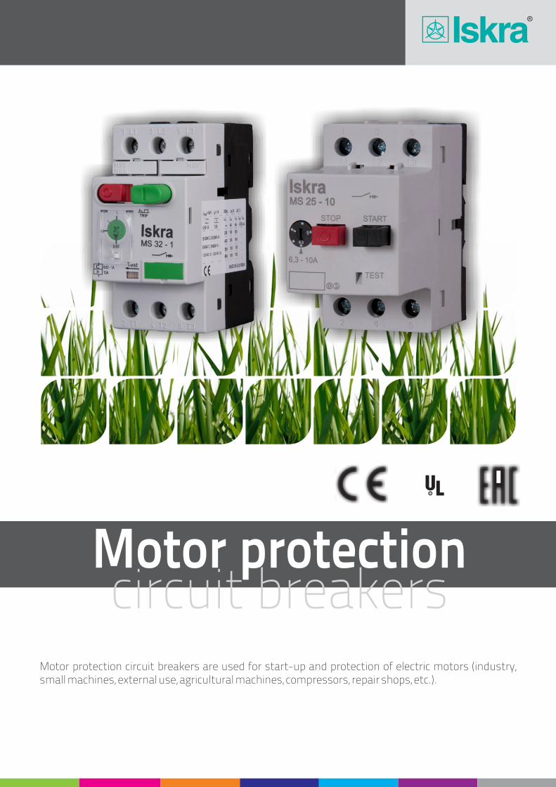
Motor protection Motor protection circuit breakers are used for start-up and protection of electric motors (industry, small machines, external use, agricultural machines, compressors, repair shops, etc.). circuit breakers R
Transcript of Motor protection breakers - Welcome - Iskra€¦ · Motor protection Motor protection circuit...
Motor protection
Motor protection circuit breakers are used for start-up and protection of electric motors (industry, small machines, external use, agricultural machines, compressors, repair shops, etc.).
circuit breakers
R
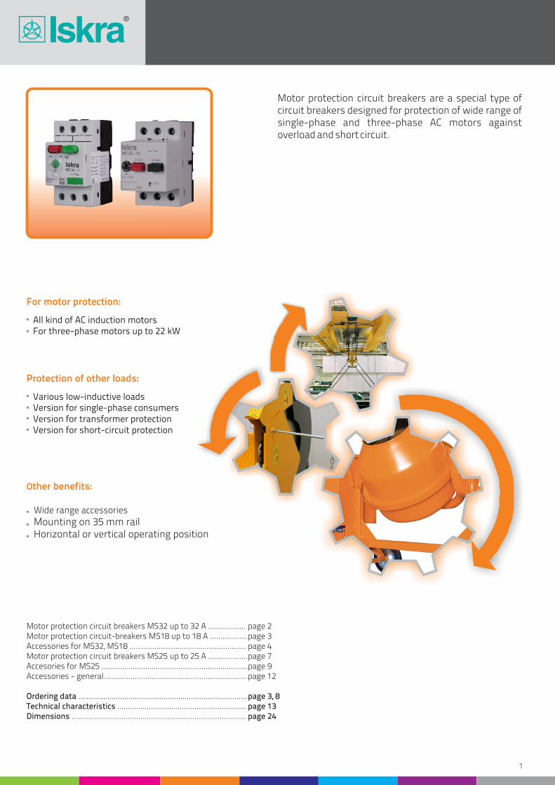
Motor protection circuit breakers are a special type of circuit breakers designed for protection of wide range of single-phase and three-phase AC motors against overload and short circuit.
Motor protection circuit breakers MS32 up to 32 A ..................Motor protection circuit-breakers MS18 up to 18 A ..................Accessories for MS32, MS18 ........................................................ Motor protection circuit breakers MS25 up to 25 A ...................Accesories for MS25 ......................................................................Accessories - general.....................................................................
Ordering data .................................................................................Technical characteristics ..............................................................Dimensions ....................................................................................
page 2page 3page 4page 7page 9 page 12
page 3, 8page 13page 24
For motor protection:
Protection of other loads:
Other benefits:
All kind of AC induction motors For three-phase motors up to 22 kW
Various low-inductive loads Version for single-phase consumers Version for transformer protection Version for short-circuit protection
Wide range accessories
Mounting on 35 mm rail Horizontal or vertical operating position
1
2
Motor protection circuit-breakers areas of use
MS32
MS32-TR
Type Motor protectionOverload
protectionShort-circuit
protectionSingle-phaseconsumers
MS18
Motor Protection Circuit BreakersMS32, MS18
with overload and short-circuit release
MS32-0.25
MS32-1
MS32-4
MS32-14
MS32-27
TypeSetting range
(A)Motor power (3-phase, 400 V)
(kW)Ordering No.
Weight(g)
Packaging(pcs)
MS32-0.16
MS32-0.63
MS32-2.5
MS32-10
MS32-23
MS32-0.4
MS32-1.6
MS32-6.3
MS32-18
MS32-32
0.1 ... 0.16
0.4 ... 0.63
1.6 ... 2.5
6.3 ... 10
17 ... 23
0.25 ... 0.4
1 ... 1.6
4 ... 6.3
13 ... 18
25 ... 32
0.09
0.37 ... 0.55
2.2
7.5
15
0.16 ... 0.25
0.63 ... 1
2.5 ... 4
9 ... 14
23 ... 27
0.06
0.18 ... 0.25
1.1 ... 1.5
5.5
11
0.12 ... 0.18
0.75
3 ... 4
9 ... 11
30.108.757
30.108.760
30.108.763
30.108.766
30.108.769
279
279
279
279
279
279
279
279
279
279
279
279
279
279
279
1
1
1
1
1
1
1
1
1
1
1
1
1
1
1
30.108.759
30.108.762
30.108.765
30.108.768
30.108.771
30.108.758
30.108.761
30.108.764
30.108.767
30.108.770
Motor protection circuit breakers MS32
with overload and short-circuit release
MS32TR-4
MS32TR-14
MS32TR-27
TypeSetting range
(A)Ordering No.
Weight(g)
Packaging(pcs)
MS32TR-2.5
MS32TR-10
MS32TR-23
MS32TR-6.3
MS32TR-18
MS32TR-32
1.6 ... 2.5
6.3 ... 10
17 ... 23
4 ... 6.3
13 ... 18
25 ... 32
2.5 ... 4
9 ... 14
23 ... 27
30.109.359
30.109.362
30.109.365
279
279
279
279
279
279
279
279
279
1
1
1
1
1
1
1
1
1
30.109.361
30.109.364
30.109.367
30.109.360
30.109.363
30.109.366
Circuit breakers for transformer protection MS32TR
AC-3 acc. to IEC/EN 60947-4-1
AC-3 acc. to IEC/EN 60947-4-1
Transformerprotection
3
Motor Protection Circuit BreakersMS32, MS18
with overload and short-circuit release
MS -0.2518
MS -118
MS -418
MS -1418
TypeSetting range
(A)Motor power (3-phase, 400 V)
(kW)Ordering No.
Weight(g)
Packaging(pcs)
MS18-0.16
MS -0.6318
MS -2.518
MS -1018
MS -0.418
MS -1.618
MS -6.318
MS -1818
0.1 ... 0.16
0.4 ... 0.63
1.6 ... 2.5
6.3 ... 10
0.25 ... 0.4
1 ... 1.6
4 ... 6.3
13 ... 18
0.09
0.37 ... 0.55
2.2
7.5
0.16 ... 0.25
0.63 ... 1
2.5 ... 4
9 ... 14
0.06
0.18 ... 0.25
1.1 ... 1.5
5.5
0.12 ... 0.18
0.75
3 ... 4
30.109.119
30.109.122
30.109.125
30.109.128
279
279
279
279
279
279
279
279
279
279
279
279
1
1
1
1
1
1
1
1
1
1
1
1
30.109.121
30.109.124
30.109.127
30.109.130
30.109.120
30.109.123
30.109.126
30.109.129
Motor protection circuit breakers MS18
MS32 – 4
Setting range (A)
Type
Ordering data
Example:The same switch with under-voltage release for control voltage 380 V with an auxiliary switch with two NO contacts, built in the enclosure, with an emergency stop push-button and green signal lamp for 230 V:
MS32 - 4 / UR 380 / HS 20 / HO41 / NAT / SSz 230
AC-3 acc. to IEC/EN 60947-4-1
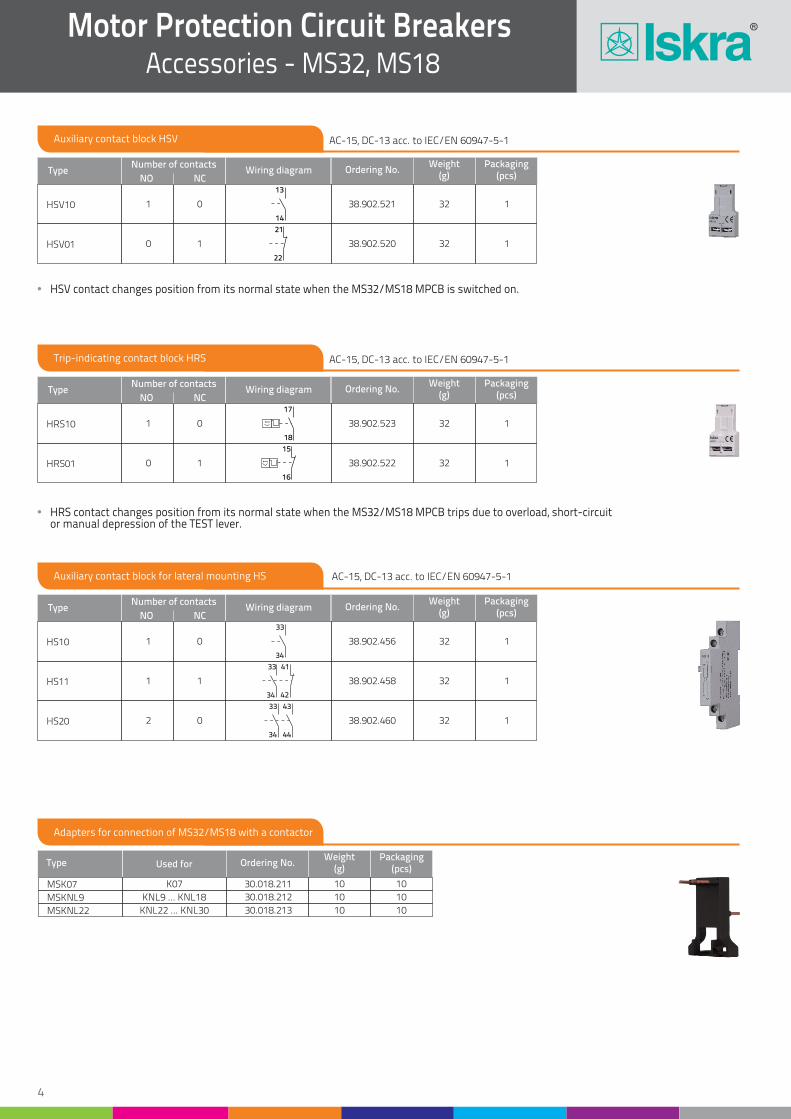
Auxiliary contact block HSV
Trip-indicating contact block HRS
Type
Type
Number of contacts
Number of contacts
NO
NO
NC
NC
Ordering No.
Ordering No.
Weight(g)
Weight(g)
Packaging(pcs)
Packaging(pcs)
HSV10
HRS10
HSV01
HRS01
1
1
0
0
0
0
1
1
38.902.521
38.902.523
38.902.520
38.902.522
32
32
32
32
1
1
1
1
Wiring diagram
Wiring diagram
HSV contact changes position from its normal state when the MS32/MS18 MPCB is switched on.
HRS contact changes position from its normal state when the MS32/MS18 MPCB trips due to overload, short-circuit or manual depression of the TEST lever.
Adapters for connection of MS32/MS18 with a contactor
MSKNL9
MSKNL22
Type Used for Ordering No.Weight
(g)Packaging
(pcs)
MSK07 K07
KNL9 ... KNL18
KNL22 ... KNL30
30.018.211 10
10
10
10
10
10
30.018.212
30.018.213
Auxiliary contact block for lateral mounting HS
TypeNumber of contacts
NO NCOrdering No.
Weight(g)
Packaging(pcs)
HS10
HS11
HS20
1
1
2
0
1
0
38.902.456
38.902.458
38.902.460
32
32
32
1
1
1
Wiring diagram
Motor Protection Circuit Breakers Accessories - MS32, MS18
4
14
13
22
21
18
17
16
15
34
33
4234
4133
4434
4333
AC-15, DC-13 acc. to IEC/EN 60947-5-1
AC-15, DC-13 acc. to IEC/EN 60947-5-1
AC-15, DC-13 acc. to IEC/EN 60947-5-1
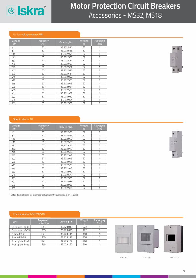
Under-voltage release UR
Shunt release AR
24
110
24
240
230
400
415
Voltage(V)*
Voltage(V)*
Frequency(Hz)
Frequency(Hz)
Ordering No.
Ordering No.
Weight(g)
Weight(g)
Packaging(pcs)
Packaging(pcs)
24
24
230
230
230
400
415
110
110
110
240
240
400
240
400
415
415
480
500
480
480
500
480
500
600
500
600
600
600
50
50
50
60
50
50
50
60
50
60
60
50
50
60
60
50
60
50
50
50
60
60
60
50
50
60
60
60
50
60
50
60
50
60
60
60
38.902.534
38.902.574
38.902.461
38.902.943
38.902.462
38.902.634
38.902.573
62
62
62
62
62
62
62
62
62
62
62
62
62
62
62
62
62
62
62
62
62
62
62
62
62
62
62
62
62
62
62
62
62
62
62
62
1
1
1
1
1
1
1
1
1
1
1
1
1
1
1
1
1
1
1
1
1
1
1
1
1
1
1
1
1
1
1
1
1
1
1
1
38.902.536
38.902.940
38.902.576
38.902.537
38.902.525
38.902.945
38.902.944
38.902.946
38.902.533
38.902.949
38.902.951
38.902.952
38.902.950
38.902.538
38.902.939
38.902.578
38.902.579
38.902.953
38.902.938
38.902.955
38.902.539
38.902.954
38.902.535
38.902.941
38.902.575
38.902.524
38.902.942
38.902.947
38.902.948
* UR and AR releases for other control voltage/frequencies are on request.
Enclosures for MS32/MS18
Enclosure HO-55
Frame FP-55
Front plate P-55
TypeDegree ofprotection
Ordering No.Weight
(g)Packaging
(pcs)
Enclosure HO-41
HO-41/55FP-41/55P-41/55
Frame FP-41
Front plate P-41
IP41
IP41
IP41
IP55
IP55
IP55
38.423.019
38.423.111
37.425.102
222
158
200
222
158
200
1
1
1
1
1
1
38.423.020
38.423.112
38.423.137
Motor Protection Circuit BreakersAccessories - MS32, MS18
5
6
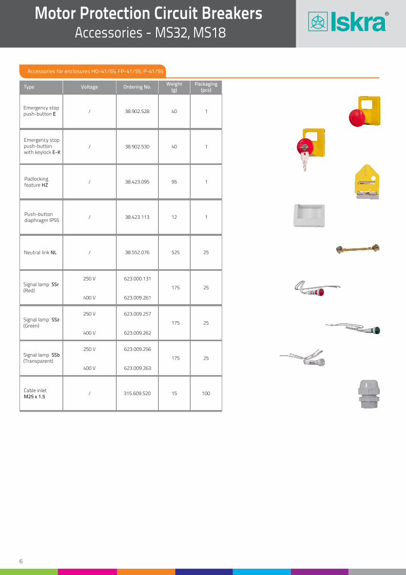
Accessories for enclosures HO-41/55, FP-41/55, P-41/55
Type Voltage Ordering No.Weight
(g)Packaging
(pcs)
Emergency stoppush-button E
Emergency stoppush-button with keylock E-K
Padlocking feature HZ
Push-buttondiaphragm IP55
Neutral link NL
Signal lamp SSr(Red)
Signal lamp SSz(Green)
Signal lamp SSb(Transparent)
Cable inletM25 x 1.5
/
/
/
/
/
/
250 V
250 V
250 V
400 V
400 V
400 V
38.902.528
38.902.530
38.423.095
38.423.113
38.552.076
623.000.131
623.009.257
623.009.256
623.009.261
623.009.262
623.009.263
315.609.520
40
40
95
12
525
175
175
175
15
1
1
1
1
25
25
25
25
100
Motor Protection Circuit Breakers Accessories - MS32, MS18
7
Motor Protection Circuit BreakersMS25
with overload and short-circuit release
with overload release
MS25-0.25
MS25-1
MST25-1
MS25-4
MST25-4
MS25-16
MST25-16
Type
Type
Setting range(A)
Setting range(A)
Motor power (3-phase, 400 V) (kW)
Motor power (3-phase, 400 V) (kW)
Ordering No.
Ordering No.
Weight(g)
Weight(g)
Packaging(pcs)
Packaging(pcs)
MS25-0.16
MS25-0.63
MST25-0.63
MS25-2.5
MST25-2.5
MS25-10
MST25-10
MS25-25
MST25-25
MS25-0.4
MST25-0.4
MS25-1.6
MST25-1.6
MS25-6.3
MST25-6.3
MS25-20
MST25-20
0.1 ... 0.16
0.4 ... 0.63
0.4 ... 0.63
1.6 ... 2.5
1.6 ... 2.5
6.3 ... 10
6.3 ... 10
20 ... 25
20 ... 25
0.25 ... 0.4
0.25 ... 0.4
1 ... 1.6
1 ... 1.6
4 ... 6.3
4 ... 6.3
16 ... 20
16 ... 20
0.09
0.09
0.37 ... 0.55
0.37 ... 0.55
2.2 ... 2.5
2.2 ... 2.5
9
9
0.16 ... 0.25
0.63 ... 1
0.63 ... 1
2.5 ... 4
2.5 ... 4
10 ... 16
10 ... 16
0.06
0.02
0.18 ... 0.25
0.18 ... 0.25
1.1 ... 1.5
1.1 ... 1.5
5 ... 7.5
5 ... 7.5
0.12
0.12
0.75 ... 1.1
0.75 ... 1.1
3 ... 4
3 ... 4
11 ... 12.5
11 ... 12.5
30.107.955
30.107.958
30.108.241
30.107.961
30.108.244
30.107.964
30.108.247
30.107.967
30.108.250
252
252
252
252
252
252
252
252
252
252
252
252
252
252
252
252
252
252
252
252
252
252
252
252
1
1
1
1
1
1
1
1
1
1
1
1
1
1
1
1
1
1
1
1
1
1
1
1
30.107.957
30.108.240
30.107.960
30.108.243
30.107.963
30.108.246
30.107.966
30.108.249
30.107.956
30.107.959
30.108.242
30.107.962
30.108.245
30.107.965
30.108.248
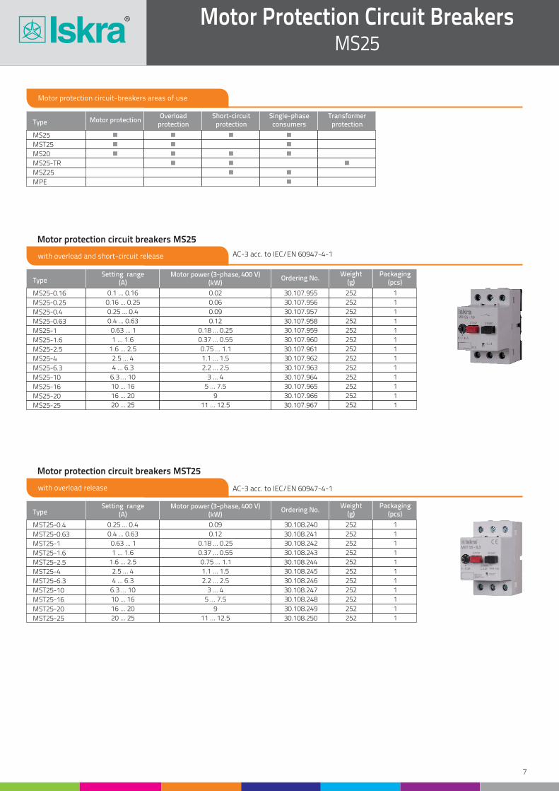
Motor protection circuit breakers MS25
Motor protection circuit breakers MST25
Motor protection circuit-breakers areas of use
MST25
MS25-TR
MPE
Type Motor protectionOverload
protectionShort-circuit
protectionSingle-phaseconsumers
Transformerprotection
M 25 S
MS20
MSZ25
AC-3 acc. to IEC/EN 60947-4-1
AC-3 acc. to IEC/EN 60947-4-1
8
Motor Protection Circuit Breakers MS25
with overload and short-circuit release
with short-circuit release
Type
Type
Setting range(A)
Setting range(A)
Motor power (3-phase, 400 V) (kW)
Motor power (3-phase, 400 V) (kW)
Ordering No.
Ordering No.
Weight(g)
Weight(g)
Packaging(pcs)
Packaging(pcs)
MPE
MSZ25-0.16
MSZ25-0.25
0.25
–
–
0.06
0.02
0.06
30.107.879
30.109.357
30.109.358
252
252
252
1
1
1
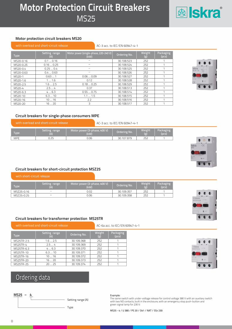
Circuit breakers for single-phase consumers MPE
Circuit breakers for short-circuit protection MSZ25
with overload and short-circuit release
MS25TR-4
MS25TR-16
TypeSetting range
(A)Ordering No.
Weight(g)
Packaging(pcs)
MS25TR-2.5
MS25TR-10
MS25TR-25
MS25TR-6.3
MS25TR-20
1.6 ... 2.5
6.3 ... 10
20 ... 25
4 ... 6.3
16 ... 20
2.5 ... 4
10 ... 16
30.109.368
30.109.371
30.109.374
252
252
252
252
252
252
252
1
1
1
1
1
1
1
30.109.370
30.109.373
30.109.369
30.109.372
Circuit breakers for transformer protection MS25TR
with overload and short-circuit release
MS20-0.25
MS20-1
MS20-4
MS20-16
TypeSetting range
(A) (kW)Motor power (single-phase, 220-240 V)
Ordering No.Weight
(g)Packaging
(pcs)
MS20-0.16
MS20-0.63
MS20-2.5
MS20-10
MS20-0.4
MS20-1.6
MS20-6.3
MS20-20
0.1 ... 0.16
0.4 ... 0.63
1.6 ... 2.5
6.3 ... 10
0.25 ... 0.4
1 ... 1.6
4 ... 6.3
16 ... 20
0.12
0.55 ... 0.75
3
0.16 ... 0.25
0.63 ... 1
2.5 ... 4
10 ... 16
–
–
–
–
0.06 ... 0.09
0.37
2.2
0.18 ... 0.25
1.1 ... 1.5
30.108.523
30.108.526
30.108.529
30.108.515
252
252
252
252
252
252
252
252
252
252
252
252
1
1
1
1
1
1
1
1
1
1
1
1
30.108.525
30.108.528
30.108.514
30.108.517
30.108.524
30.108.527
30.108.513
30.108.516
Motor protection circuit breakers MS20
MS25 – 4
Setting range (A)
Type
Ordering data
Example:The same switch with under-voltage release for control voltage 380 V with an auxiliary switch with two NO contacts, built in the enclosure, with an emergency stop push-button and green signal lamp for 230 V:
MS25 - 4 / U 380 / PS 20 / O41 / NAT / SSz 230
AC-3 acc. to IEC/EN 60947-4-1
AC-3 acc. to IEC/EN 60947-4-1
AC-6a acc. to IEC/EN 60947-4-1
9
Motor Protection Circuit BreakersAccessories - MS25
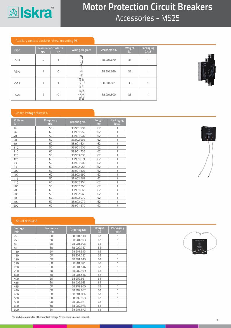
Auxiliary contact block for lateral mounting PS
TypeNumber of contacts
NO NCOrdering No.
Weight(g)
Packaging(pcs)
PS01
PS11
PS10
PS20
0
1
1
2
1
1
0
0
38.901.670
38.901.501
38.901.669
38.901.500
35
35
35
35
1
1
1
1
Wiring diagram
Under-voltage release U
Shunt release A
24
24
60
230
400
120
120
415
500
415
500
Voltage(V)*
Voltage(V)*
Frequency(Hz)
Frequency(Hz)
Ordering No.
Ordering No.
Weight(g)
Weight(g)
Packaging(pcs)
Packaging(pcs)
24
24
48
48
110
110
400
415
500
48
48
110
110
400
400
120
415
500
480
600
480
600
120
230
480
600
480
600
230
230
50
50
60
60
60
60
60
50
50
50
50
50
50
50
60
60
60
60
50
50
60
60
60
50
50
50
60
60
50
60
60
60
50
60
50
50
50
50
50
60
60
38.901.502
38.901.510
38.902.956
38.902.957
38.901.726
38.901.727
38.902.960
38.902.963
38.902.969
62
62
62
62
62
62
62
62
62
62
62
62
62
62
62
62
62
62
62
62
62
62
62
62
62
62
62
62
62
62
62
62
62
62
62
62
62
62
62
62
62
1
1
1
1
1
1
1
1
1
1
1
1
1
1
1
1
1
1
1
1
1
1
1
1
1
1
1
1
1
1
1
1
1
1
1
1
1
1
1
1
1
38.901.904
38.901.905
38.901.505
38.901.513
38.901.508
38.902.961
38.901.871
38.902.964
38.902.970
38.902.967
38.902.973
38.901.864
38.901.872
38.901.871
38.901.514
38.902.966
38.902.972
38.901.863
38.901.870
38.901.506
38.902.959
38.901.952
38.901.953
38.901.504
38.902.958
38.901.516
38.903.035
38.901.973
38.902.962
38.902.968
38.902.965
38.902.971
* U and A releases for other control voltage/frequencies are on request.
14
13
33
34
2214
2113
44 32
43 31
2314
2313
44 34
43 33
12
11
31
32

10
Motor Protection Circuit BreakersAccessories - MS25
Trip-indicating auxiliary contact block RS
TypeNumber of contacts
NO NCOrdering No.
Weight(g)
Packaging(pcs)
RS01
RS10
0
1
1
0
38.902.149
38.902.150
35
35
1
1
Wiring diagram
RS contact changes position from its normal state when the MS25 MPCB trips due to overload, short-circuit or the manual depression of the TEST lever.
Enclosures for MS25
Enclosure O-55
Front plate CP-55
TypeDegree ofprotection
Ordering No.Weight
(g)Packaging
(pcs)
Enclosure O-41
Front plate CP-41
IP41
IP41
IP55
IP55
38.422.509
38.422.035
222
150
222
150
1
1
1
1
38.422.510
38.421.994
Adapters for connection of MS25 with a contactor
DST-U-4
DST-U-2.5 L
TypeConductor lenght
(mm)Conductor
2cross-section (mm )Thermal current
(A)Ordering No.
Weight(g)
Packaging(pcs)
DST-U-2.5 40 2.5 20
20
35
2.5
40 4
70
665.200.020 12
16
14
10
10
10
665.200.021
665.200.022
52
51
54
53
O-41/55CP-41/55
11
Motor Protection Circuit BreakersAccessories - MS25
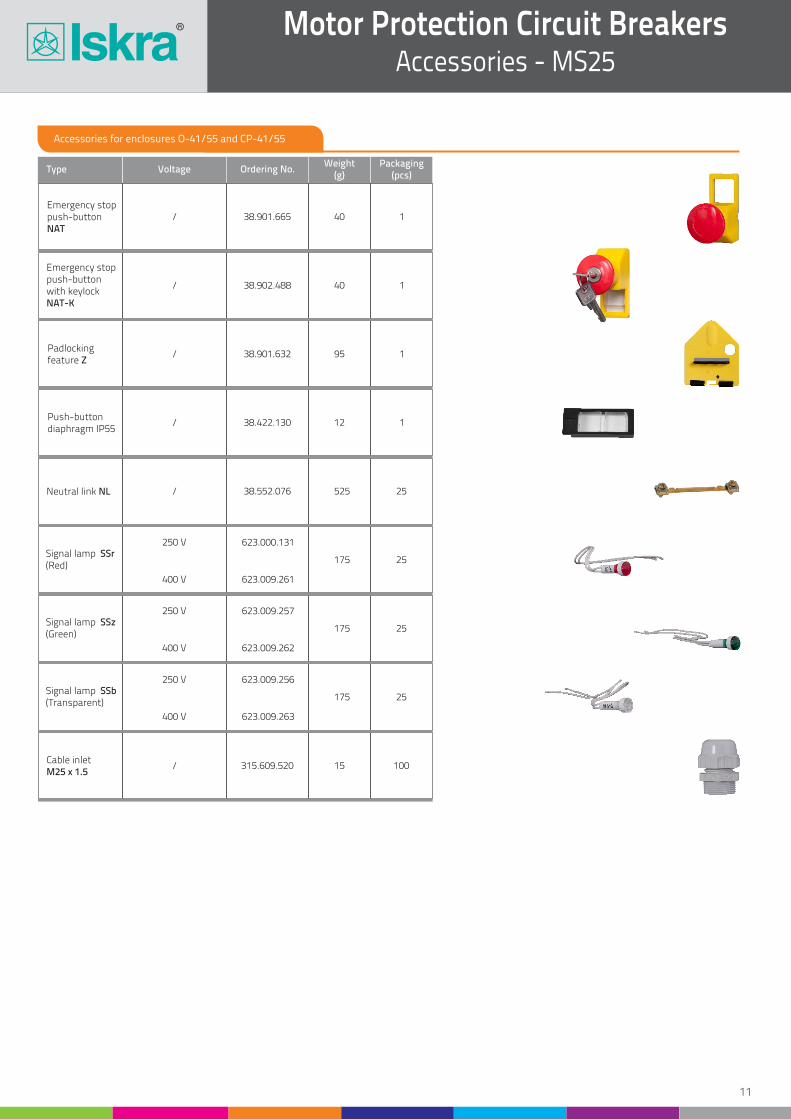
Accessories for enclosures O-41/55 and CP-41/55
Type Voltage Ordering No.Weight
(g)Packaging
(pcs)
Emergency stoppush-button NAT
Emergency stoppush-button with keylock NAT-K
Padlocking feature Z
Push-buttondiaphragm IP55
Neutral link NL
Signal lamp SSr(Red)
Signal lamp SSz(Green)
Signal lamp SSb(Transparent)
Cable inletM25 x 1.5
/
/
/
/
/
/
250 V
250 V
250 V
400 V
400 V
400 V
38.901.665
38.902.488
38.901.632
38.422.130
38.552.076
623.000.131
623.009.257
623.009.256
623.009.261
623.009.262
623.009.263
315.609.520
40
40
95
12
525
175
175
175
15
1
1
1
1
25
25
25
25
100
12
Motor Protection Circuit BreakersAccessories
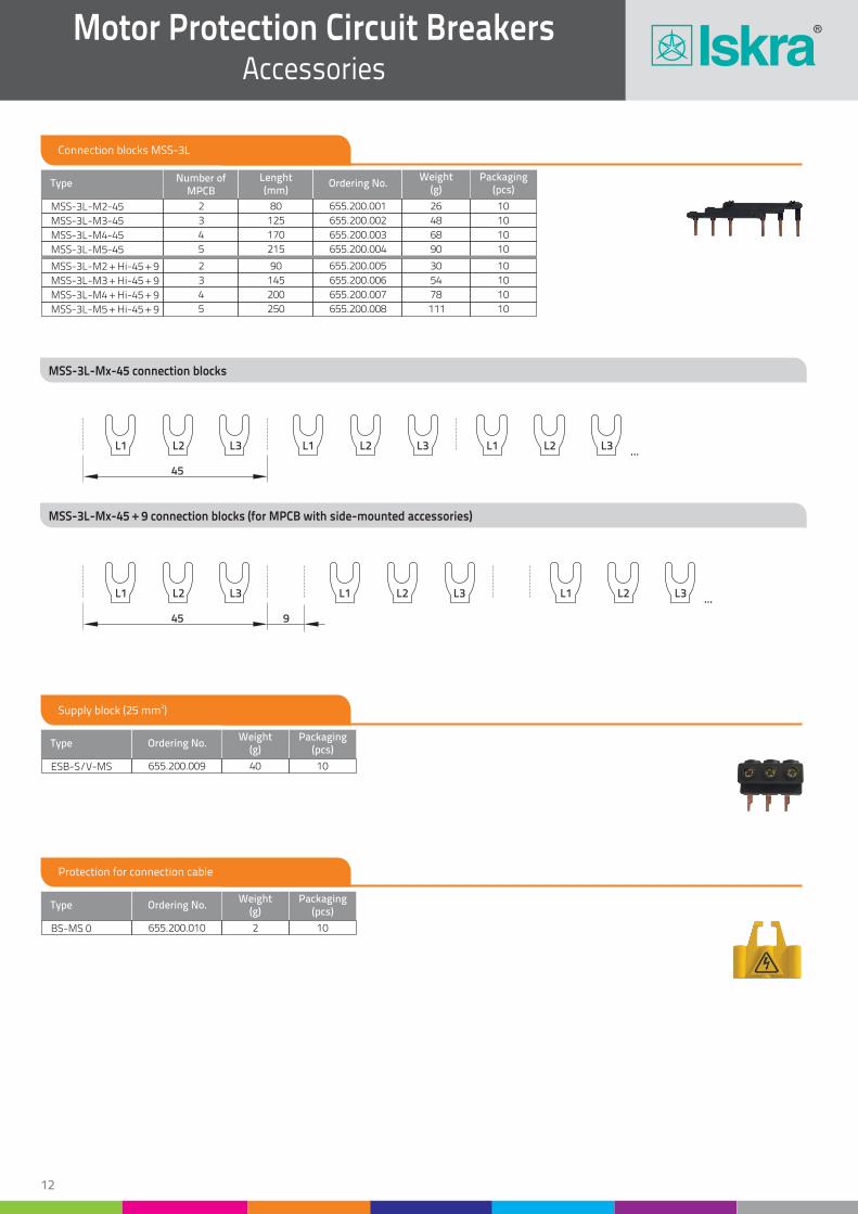
Connection blocks MSS-3L
2Supply block (25 mm )
Protection for connection cable
MSS-3L-M3-45
MSS-3L-M3 + Hi-45 + 9
MSS-3L-M4-45
MSS-3L-M4 + Hi-45 + 9
MSS-3L-M5-45
MSS-3L-M5 + Hi-45 + 9
Type Number of MPCB
Lenght(mm)
Ordering No.Weight
(g)Packaging
(pcs)
MSS-3L-M2-45
MSS-3L-M2 + Hi-45 + 9
2
2
80
90
3
3
125
145
4
4
5
5
170
200
215
250
655.200.001
655.200.005
26
30
48
54
68
78
90
111
10
10
10
10
10
10
10
10
655.200.002
655.200.006
655.200.003
655.200.007
655.200.004
655.200.008
MSS-3L-Mx-45 connection blocks
MSS-3L-Mx-45 + 9 connection blocks (for MPCB with side-mounted accessories)
Type
Type
Ordering No.
Ordering No.
Weight(g)
Weight(g)
Packaging(pcs)
Packaging(pcs)
ESB-S/V-MS
BS-MS 0
655.200.009
655.200.010
40
2
10
10
45
L1 L2 L3 L1 L2 L3 L1 L2 L3...
45 9
L1 L2 L3 L1 L2 L3 L1 L2 L3...

Technical characteristicsDimensions
i
14
Motor Protection Circuit BreakersMS32, MS18
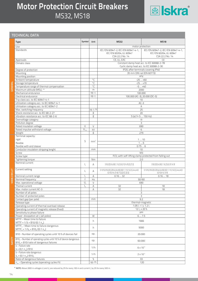
TECHNICAL DATA
Standards
Use
Approvals
Climatic class
Degree of protection
Mounting
Mounting position
Ambient temperature
Storage temperature
Temperature range of thermal compensation
Mechanical endurance
Electrical endurance
Trip class acc. to IEC 60947-4-1
Utilization category acc. to IEC 60947-4-1
Utilization category acc. to IEC 60947-2
Max. switching frequency
Shock resistance acc. to IEC 68-2-27
Vibration resistance acc. to IEC 68-2-6
Overvoltage category
Pollution degree
Rated insulation voltage
Conductor insulation stripping lenght
Screw
Screw type
Tightening torque
Nominal current range
Nominal frequency
Max. operational voltage
Themal current
Max. motor current AC-3
Number of all poles
Number of protected poles
Contact gap (per pole)
Release type
Operating current of thermal overload release
Operating current of magnetic release (fixed)
Sensitivity to phase failure
MTTF - Mean time to failure
MTTF - Mean time to failure dangerousd
B10 - Number of operating cycles until 10 % of device dangerousd
λ - Failure rate
λ - Failure rate dangerous
B10 - Number of operating cycles until 10 % of devices fail
Power dissipation at I (all poles)n
Ratio of dangerous failures
n - Operating cycles (operating cycles/h)op
MTTF = 1/λ = B10/(0.1 n )op
MTTF = 1/λ = B10 /(0.1 n )d d d op
B10 = B10/ratio of dangerous failuresd
λ = (0,1 n )/B10op
λ = (0,1 n )/B10d op d
Rated impulse withstand voltage
Weight
IEC/EN 60947-2, IEC/EN 60947-4-1, IEC/EN 60947-2, IEC/EN 60947-4-1, IEC/EN 60204, UL 60947 IEC/EN 60204, UL 60947
CSA 22.2 No. 14 CSA 22.2 No. 14
motor protection
CECE, UL, EAC
Constant damp heat acc. to IEC 60068-2-78
Cyclic damp heat acc. to IEC 60068-2-30
°C
°C
°C
op. c.
op. c.
g
g
V
kVg
IP20, after terminals covering IP40
35 mm DIN rail (EN 60715)any
-25 … +60
-25 … +70
-5 … +40
100.000
100.000 (AC-3), 20.000 (DC-5)
10
AC-3
A
25
20
5 (at f= 5 ... 150 Hz)
III
3
690
6
279
GE
NE
RA
LM
AIN
CIR
CU
ITS
AF
ETY
Symbol Unit MS32 MS18Type
op. c./h
Ui
Uimp
Terminal capacity:
rigid
flexible
flexible with end sleeve
1 … 10
1 … 6
0.75 … 6
10
M3PZ2, with self-lifting clamp protected from falling out
2.0
0.16 ... 32
50/60
690
32
32
3
3
9.2thermal-magnetic
1.05 I < I < 1.2 Ir r
12 I ± 20 %n
yes
6 ... 7.5
33
120
1666
5000
60.000
-46 x 10
-42 x 10
20.000
18
18
0.16 ... 18
S
In
fUe
Ith
2mm
mm
mm
W
%op./h
h
h
op.
1/h
1/h
op.
Nm
A
Hz
V
A
A
Maximum altitude (MSL) * m 2000
Nominal current
Current setting
In
IT
0.16, 0.25, 0.4, 0.63, 1, 1.6, 2.5, 6.3, 10, 14, 18, 23, 27, 32 0.16, 0.25, 0.4, 0.63, 1, 1.6, 2.5, 6.3, 10, 14, 18
0.1-0.16, 0.16-0.25, 0.25-0.4, 0.4-0.63, 0.63-1, 1-1.6, 1.6-2.5, 2.4-4, 4-6.3 0.1-0.16, 0.16-0.25, 0.25-0.4, 0.4-0.63, 0.63-1, 1-1.6, 1.6-2.5, 2.4-4, 4-6.36.3-10, 9-14, 13-18, 17-23, 20-27, 25-32 6.3-10, 9-14, 13-18
A
A
* NOTE: Above 2000 m voltages U and U are reduced by 2% for every 100 m and current I by 2% for every 500 m.i e e
15
Motor Protection Circuit BreakersMS32, MS18
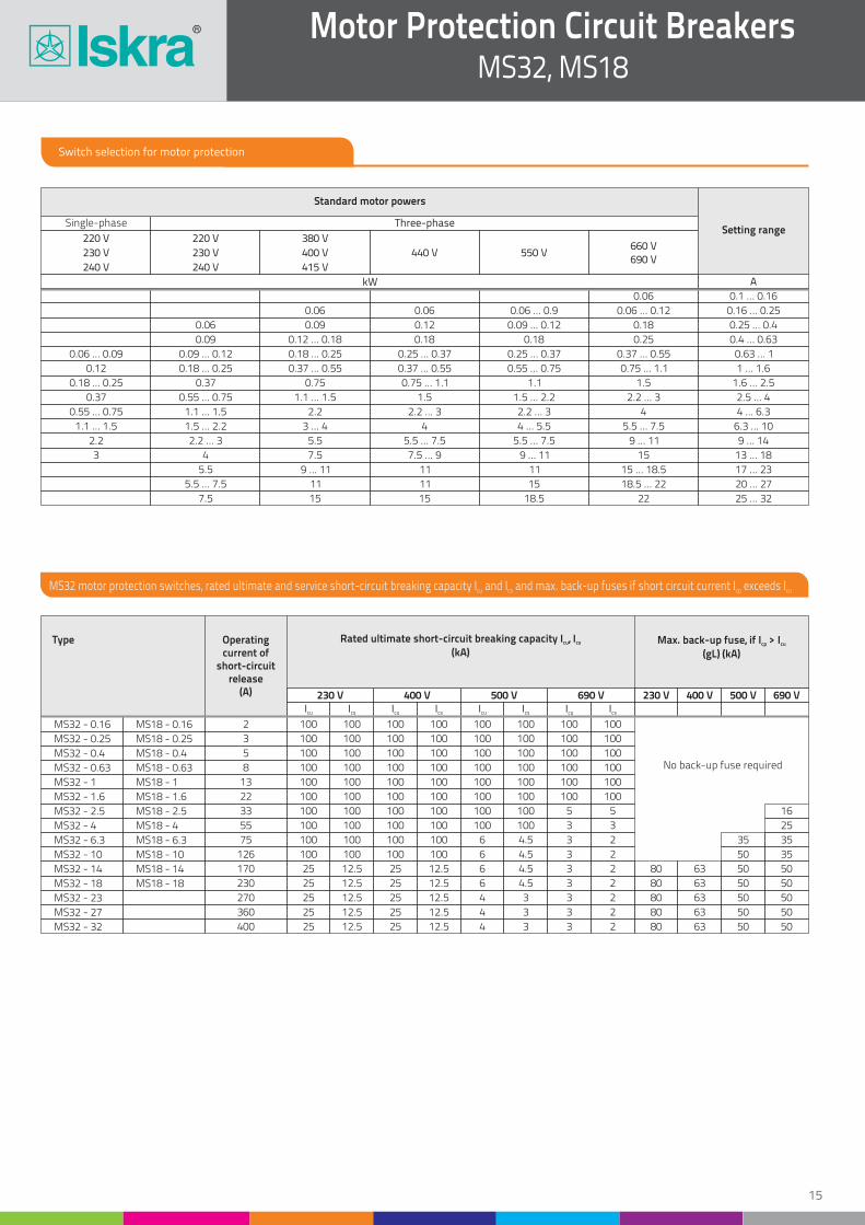
Switch selection for motor protection
Three-phaseSingle-phase
440 V 550 V
0.06 ... 0.09
0.06
0.06 0.06
0.06 0.1 ... 0.16
0.16 ... 0.25
0.25 ... 0.4
0.4 ... 0.63
0.63 ... 1
1 ... 1.6
1.6 ... 2.5
2.5 ... 4
4 ... 6.3
6.3 ... 10
9 ... 14
13 ... 18
17 ... 23
20 ... 27
25 ... 32
0.06 ... 0.9 0.06 ... 0.12
0.09 ... 0.12
0.09
0.09 0.12
0.09 ... 0.12
0.12 ... 0.18 0.18 0.18
0.18
0.18 ... 0.25
0.18 ... 0.25 0.25 ... 0.37 0.25 ... 0.37 0.37 ... 0.55
0.25
0.37 ... 0.55 0.55 ... 0.75 0.75 ... 1.1
0.75 ... 1.1 1.1
2.2 ... 3 2.2 ... 3
2.2 ... 31.5 1.5 ... 2.2
1.5
0.37 ... 0.55
0.37
2.2
5.5
7.5
0.75
0.55 ... 0.75
1.1 ... 1.5
1.1 ... 1.5
3 ... 4 4
4
4 ... 5.5
9 ... 11
5.5 ... 7.5 5.5 ... 7.5
15 ... 18.5
18.5 ... 22
5.5 ... 7.5
7.5 ... 9 9 ... 11
9 ... 11
11 11
11 11
15 15 18.5
15
22
15
1.5 ... 2.2
2.2 ... 3
4
5.5
5.5 ... 7.5
7.5
0.18 ... 0.25
0.55 ... 0.75
MS32 - 0.16
MS32 - 0.25
MS32 - 0.4
MS32 - 0.63
MS32 - 1
MS32 - 1.6
MS32 - 2.5
MS32 - 4
MS32 - 6.3
MS32 - 10
MS32 - 14
MS32 - 18
MS32 - 23
MS32 - 27
MS32 - 32
MS18 - 0.16
MS18 - 0.25
MS18 - 0.4
MS18 - 0.63
MS18 - 1
MS18 - 1.6
MS18 - 2.5
MS18 - 4
MS18 - 6.3
MS18 - 10
MS18 - 14
MS18 - 18
2
3
5
8
13
22
33
55
75
126
170
230
270
360
400
100
100
100
100
100
100
100
100
100
100
25
25
25
25
25
100
100
100
100
100
100
100
100
100
100
12.5
12.5
12.5
12.5
12.5
100
100
100
100
100
100
No back-up fuse required
100
100
100
100
25
25
25
25
25
100
100
100
100
100
100
100
100
100
100
12.5
12.5
12.5
12.5
12.5
100
100
100
100
100
100
100
100
6
6
6
6
4
4
4
100
100
100
100
100
100
100
100
4.5
4.5
4.5
4.5
3
3
3
100
100
100
100
100
100
5
3
3
3
3
3
3
3
3
100
100
100
100
100
100
5
3
2
2
2
2
2
2
2
80
80
80
80
80
63
63
63
63
63
50
50
50
50
50
50
50
50
50
50
50
3535
25
16
35
0.12
0.37
2.2
3
1.1 ... 1.5
kW
230 V 400 V 500 V 690 V 230 V 400 V 500 V 690 VIcu Icu Icu IcuIcs Ics Ics Ics
A
660 V690 V
220 V
230 V
240 V
220 V
230 V
240 V
380 V
400 V
415 V
Standard motor powers
Setting range
MS32 motor protection switches, rated ultimate and service short-circuit breaking capacity I and I and max. back-up fuses if short circuit current I exceeds Icu cs cp cu
Operatingcurrent of
short-circuitrelease
(A)
Rated ultimate short-circuit breaking capacity I , Icu cs
(kA)Max. back-up fuse, if I > Icp cu
(gL) (kA)
Type
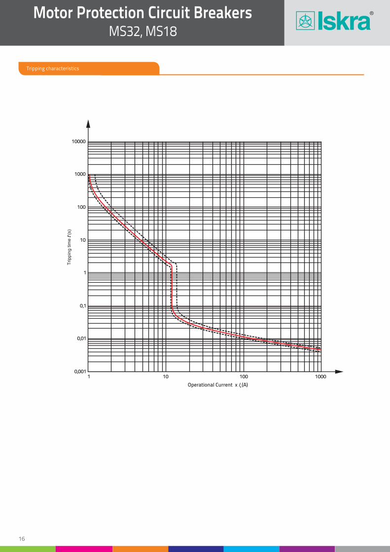
1 10 100 10000,001
0,01
0,1
1
10
100
1000
10000
Operational Current x (A)e I
Trippin
g t
ime
(s)
t
Motor Protection Circuit BreakersMS32, MS18
Tripping characteristics
16
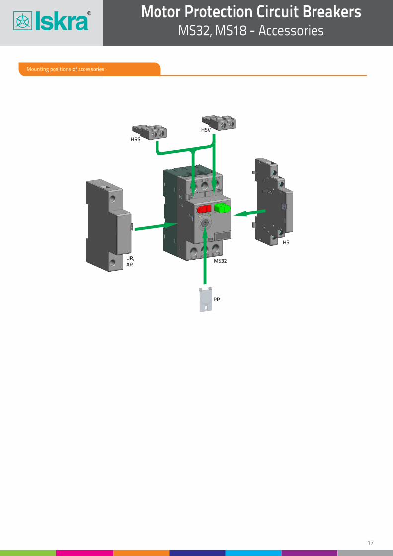
Mounting positions of accessories
PP
HS
UR,AR
MS32
HSV
HRS
Motor Protection Circuit BreakersMS32, MS18 - Accessories
17
TECHNICAL DATA
TECHNICAL DATA
TECHNICAL DATA
Standards
Approvals
Standards
Approvals
Control voltages (AC)
Approvals
Standards
Rated impulse voltage
Rated insulation voltage
Rated impulse voltage
Rated insulation voltage
Rated frequency
Thermal current
Thermal current
Pick-up voltage
Rated operational current AC-15 (240 V)
Rated operational current AC-15 (240 V)
Drop-out voltage
Rated operational current DC-13 (250 V)
Contact rating code designation for AC/DC
Rated operational current DC-13 (125 V)
Contact rating code designation for AC/DC
Duty cycle
Noise level
Mechanical and electrical endurance
Terminal capacity
Conductor insulation stripping length
Screw type
Screw head
Tightening torque
Mechanical endurance
Electrical endurance
Mechanical endurance
Electrical endurance
Terminal capacity
Conductor insulation stripping length
Terminal capacity
Conductor insulation stripping length
Screw type
Screw type
Screw head
Screw head
Tightening torque
Tightening torque
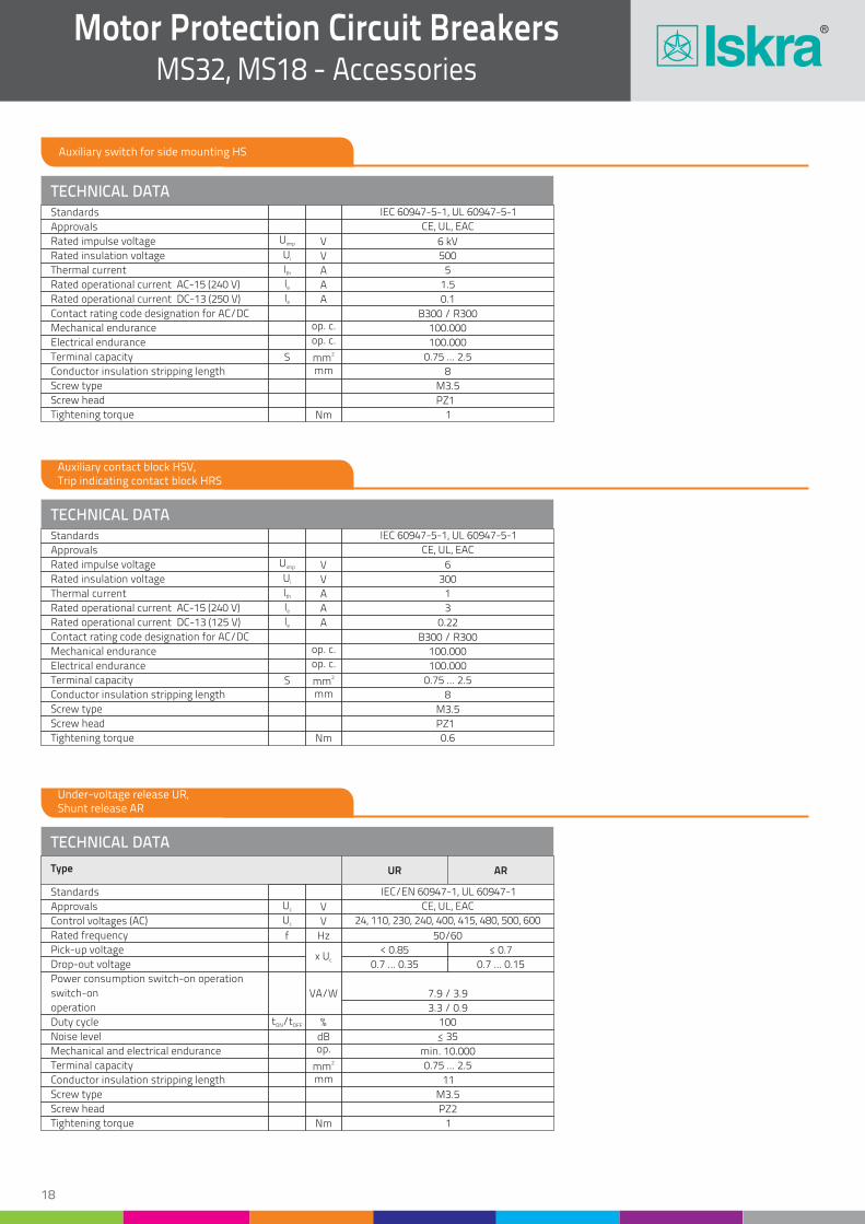
IEC 60947-5-1, UL 60947-5-1
CE, UL, EAC
IEC 60947-5-1, UL 60947-5-1
CE, UL, EAC
24, 110, 230, 240, 400, 415, 480, 500, 600
CE, UL, EAC
IEC/EN 60947-1, UL 60947-1
op. c.
op. c.
op. c.
op. c.
V
V
V
V
Hz
V
V
A
A
x Uc
A
A
A
A
%
dBop.
2mmmm
Nm
Nm
Nm
6 kV
500
6
300
50/60
5
1
< 0.85 < 0.7
1.5
3
0.7 ... 0.35 0.7 ... 0.15
0.1
B300 / R300
B300 / R300
0.22
100
< 35
min. 10.000
0.75 ... 2.5
11
M3.5
PZ2
1
100.000
100.000
100.000
100.000
0.75 ... 2.5
8
0.75 ... 2.5
8
M3.5
M3.5
PZ1
PZ1
1
0.6
Uimp
Ui
Uimp
Ui
f
t /tON OFF
Uc
Uc
Ith
Ith
Ie
Ie
Ie
Ie
S
S
2mmmm
2mmmm
Auxiliary switch for side mounting HS
Auxiliary contact block HSV, Trip indicating contact block HRS
Under-voltage release UR, Shunt release AR
Type UR AR
Motor Protection Circuit BreakersMS32, MS18 - Accessories
18
Power consumption switch-on operation
switch-on
operation
VA/W 7.9 / 3.9
3.3 / 0.9
TECHNICAL DATA
Standards
Use
Approvals
Climatic class
Degree of protection
Mounting
Mounting position
Ambient temperature
Storage temperature
Temperature range of thermal compensation
Maximum altitude (MSL) *
Mechanical endurance
Electrical endurance
Trip class acc. to IEC 60947-4-1
Utilization category acc. to IEC 60947-4-1
Utilization category acc. to IEC 60947-2
Max. switching frequency
Shock resistance acc. to IEC 68-2-27
Vibration resistance acc. to IEC 68-2-6
Overvoltage category
Pollution degree
Rated insulation voltage
Conductor insulation stripping lenght
Screw
Screw type
Tightening torque
Nominal current
Current setting
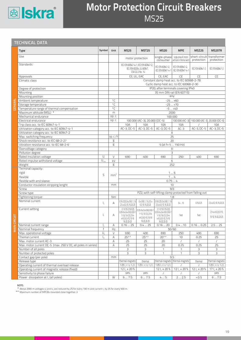
NOTE:
* Above 2000 m voltages U and U are reduced by 2% for every 100 m and current I by 2% for every 500 m.i e e
** Maximum number of MPCBs mounted close together: 3
Nominal current range
Nominal frequency
Max. operational voltage
Themal current
Max. motor current AC-3
Max. motor current DC-5 (max. 250 V DC, all poles in series)
Number of all poles
Number of protected poles
Contact gap (per pole)
Release type
Operating current of thermal overload release
Operating current of magnetic release (fixed)
Sensitivity to phase failure
Power dissipation at I (all poles)n
Rated impulse withstand voltage
Weight
IEC/EN 60947-2 IEC/EN 60947-2IEC/EN 60947-2,IEC/EN 60947-4-1
IEC/EN 60947-2,IEC/EN 60947-4-1
IEC/EN 60947-4-1, IEC/EN 60947-2,IEC/EN 60204, UL 60947,
CSA 22.2 No. 14
motor protection short-circuit protection
transformerprotection
single-phaseconsumer
single-phase AC motors with built-in thermal switch
CE, UL, EAC CE, EAC CECECEConstant damp heat acc. to IEC 60068-2-78
Cyclic damp heat acc. to IEC 60068-2-30
°C
°C
°Cm
op. c.
op. c.
g
g
V
kVg
IP20, after terminals covering IP40
35 mm DIN rail (EN 60715)any
-25 … +60
-25 … +70
-5 … +40
2000
100.000
100.000 (AC-3), 20.000 (DC-5) 100.000 (AC-3), 20.000 (DC-5)100.000 (AC-3)
10A 10A 10A 10A / 10A
AC-3, DC-5 AC-3, DC-5 AC-3, DC-5 AC-3, DC-5AC-3, DC-5AC-3
A
25
20
5 (at f= 5 ... 150 Hz)
III
3
690 690 250 690400
400
400
400
6
252
GE
NE
RA
LM
AIN
CIR
CU
IT
Symbol UnitType
op. c./h
Ui
Uimp
In
IT
Terminal capacity:
rigid
flexible
flexible with end sleeve
1 … 6
1 … 4
0.75 … 4
10
M3PZ2, with self-lifting clamp protected from falling out
1.8
0.16, 0.25, 0.4, 0.63, 1, 1.6
0.1-0.16, 0.16-0.25, 0.1-0.16, 0.16-0.25,
1-1.6, 1.6-2.5, 2.5-4 1-1.6, 1.6-2.5, 2.5-42.5-4, 4-6.3, 6.3-10,
1-1.6, 1.6-2.5, 2.5-4 fixed fixed
0.16, 0.25, 0.4, 0.63, 1, 1.60.4, 0.63, 1, 1.6, 2.5, 40.4 ... 10 0.16, 0.25 2.5, 4, 6.3, 10, 16, 20, 25
2.5, 4, 6.3, 10, 16, 20, 25
0.25-0.4, 0.4-0.63, 0.63-1 0.25-0.4, 0.4-0.63, 0.63-10.25-0.4, 0.4-0.63, 0.63-1
4-6.3, 6.3-10, 10-16 4-6.3, 6.3-10, 10-1610-16, 16-20, 20-254-6.3, 6.3-10, 10-16
16-20, 20-25 16-20, 20-2516-20, 20-25
2.5, 4, 6.3, 10, 16, 20, 256.3, 10, 16, 20, 25
0.16 ... 25 0.16 ... 20 0.16 ... 0.25 2.5 ... 250.4 ... 25
50/60
690 690 250 690
25**
25
25
25** 25
25
20**
20
10
20
/
0.25 0.25
0.4 ...10
25
25
3
3
3
3
3
3
3
3
1
1
1
1
9.5thermal-magnetic thermal-magnetic thermal-magnetic thermal-magneticthermal thermal
12 I ± 20 %n 12 I ± 20 %n 12 I ± 20 %n 12 I ± 20 %n 17 I ± 20 %n
yes yes yes
6 ... 7.5 6 ... 7.5 4 ... 5 2 ... 2.5 0.5~~ 6 ... 7.5
0.25
/
//
///
/
S
In
fUe
Ith
2mm
mm
mm
W
Nm
A
A
A
Hz
V
A
A
A
1.05 I < I < 1.2 Ir r 1.05 I < I < 1.2 Ir r 1.05 I < I < 1.2 Ir r 1.05 I < I < 1.2 Ir r
MS25 MST25 MS20 MPE MSZ25 MS25TR
Motor Protection Circuit BreakersMS25
19
Switch selection for motor protection
Three-phaseSingle-phase
440 V 550 V
0.06 ... 0.09
0.06
0.06
0.02
0.06
0.06 0.1 ... 0.16
0.16 ... 0.25
0.25 ... 0.4
0.4 ... 0.63
0.63 ... 1
1 ... 1.6
1.6 ... 2.5
2.5 ... 4
4 ... 6.3
6.3 ... 10
10 ... 16
16 ... 20
20 ... 25
0.06 0.09
0.12
0.09
0.09 0.12
0.09 ... 0.12
0.12 0.18 0.25
0.18
0.18 ... 0.25
0.18 ... 0.25 0.25 0.37 0.37 ... 0.55
0.25
0.37 ... 0.55 0.55 ... 0.8 0.75 ... 1.1
0.75 ... 1.1 1.1
2.2 ... 3 3
2.2 ... 31.5 1.5 ... 2.2
1.5
0.37 ... 0.55
0.37
2.2 ... 2.5
5 ... 7.5
9
0.75 ... 1.1
0.55 ... 0.75
1.1 ... 1.5
1.1 ... 1.5
3 ... 4 4 ... 5
4
4 ... 5.5
11 ... 12.5
5.5 ... 9 7.5 ... 9
18.5
5.5 ... 7.5
11 11 ... 12.5
11
12.5 15
15
1.5 ... 2.5
3 ... 4
5.5
5.5 ... 7.5
0.18 ... 0.25
0.55 ... 0.75
MS25 - 0.16
MS25 - 0.25
MS25 - 0.4
MS25 - 0.63
MS25 - 1
MS25 - 1.6
MS25 - 2.5
MS25 - 4
MS25 - 6.3
MS25 - 10
MS25 - 16
MS25 - 20
MS25 - 25
2
3
5
8
13
22
33
55
84
126
170
230
270
50 50 50 50
50 50 50 50
50 50 50 50
50 50 50 50
50 50 50 50
50 50 50 50
50 50 3 2.5
2.5
2.5
2.5
50 50 3
50 50 3
50 6 3
6 4 2.5 2
2
2
6 4 2.5
6 4 2.5
No back-up fuse required
80
80
80
80
80
80
80
63
63
63
50
35
50
50
3550
25
2025
35
35
0.12
0.37
2.2
3
1.1 ... 1.5
kW
230 V 400 V 500 V 690 V 230 V 400 V 500 V 690 VIcu Icu Icu Icu
A
660 V690 V
220 V
230 V
240 V
220 V
230 V
240 V
380 V
400 V
415 V
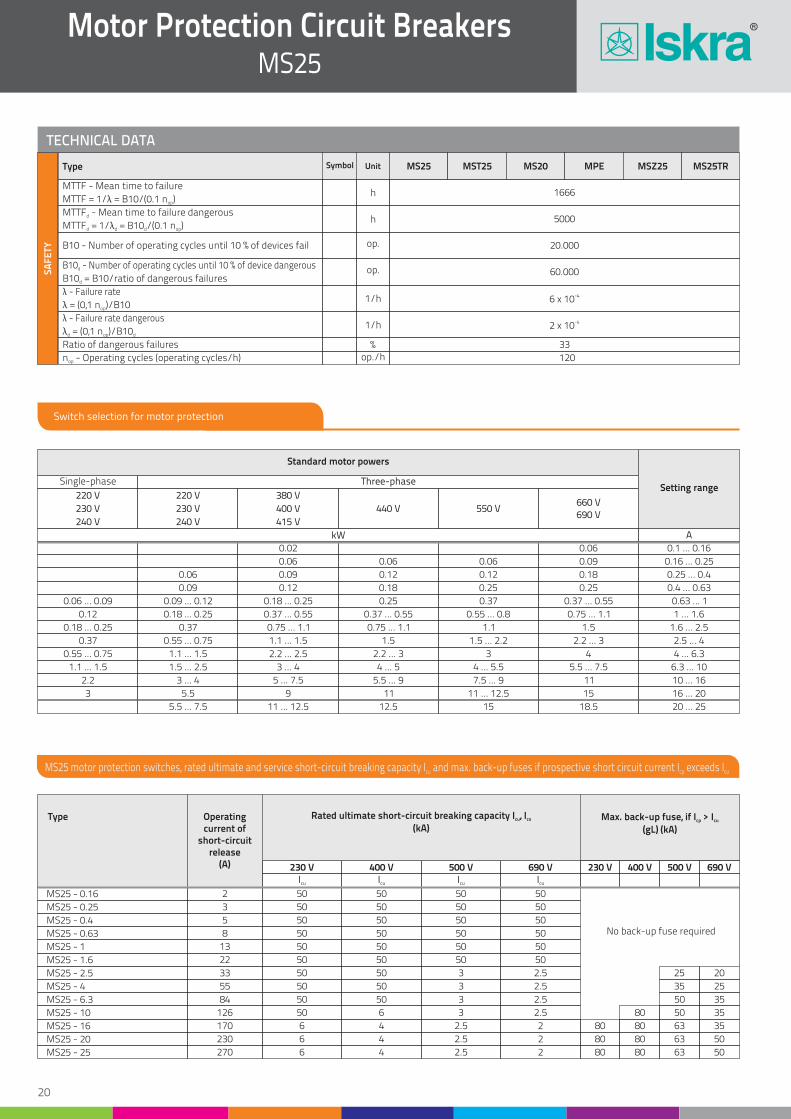
Standard motor powers
Setting range
MS25 motor protection switches, rated ultimate and service short-circuit breaking capacity I and max. back-up fuses if prospective short circuit current I exceeds Icu cp cu
Operatingcurrent of
short-circuitrelease
(A)
Rated ultimate short-circuit breaking capacity I , Icu cs
(kA)Max. back-up fuse, if I > Icp cu
(gL) (kA)
Type
Motor Protection Circuit BreakersMS25
20
TECHNICAL DATA
Symbol UnitType MS25 MST25 MS20 MPE MSZ25 MS25TR
MTTF - Mean time to failure
MTTF - Mean time to failure dangerousd
B10 - Number of operating cycles until 10 % of device dangerousd
λ - Failure rate
λ - Failure rate dangerous
B10 - Number of operating cycles until 10 % of devices fail
Ratio of dangerous failures
n - Operating cycles (operating cycles/h)op
MTTF = 1/λ = B10/(0.1 n )op
MTTF = 1/λ = B10 /(0.1 n )d d d op
B10 = B10/ratio of dangerous failuresd
λ = (0,1 n )/B10op
λ = (0,1 n )/B10d op d
SA
FE
TY
33
120
1666
5000
60.000
-46 x 10
-42 x 10
20.000
%op./h
h
h
op.
1/h
1/h
op.
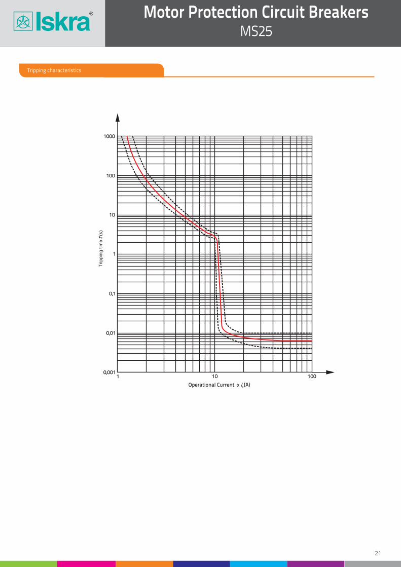
Tripping characteristics
Motor Protection Circuit BreakersMS25
21
1 10 1000,001
0,01
0,1
1
10
100
1000
Trippin
g t
ime
(s)
t
Operational Current x (A)e I
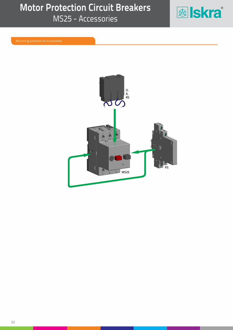
MS25
PS
U,A,RS
Mounting positions of accessories
Motor Protection Circuit BreakersMS25 - Accessories
22
Motor Protection Circuit BreakersMS25 - Accessories
23
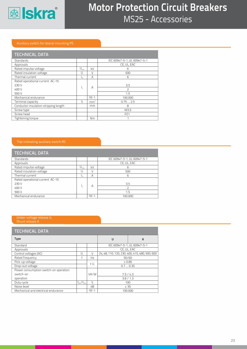
TECHNICAL DATA
TECHNICAL DATA
TECHNICAL DATA
Standards
Approvals
Rated impulse voltage
Standards
Approvals
Control voltages (AC)
Approvals
Standard
Rated insulation voltage
Rated insulation voltage
Rated impulse voltage
Rated frequency
Thermal current
Thermal current
Pick-up voltage
Rated operational current AC-15
Rated operational current AC-15
Drop-out voltage
230 V
230 V
400 V
400 V
500 V
500 V
Power consumption switch-on operation
switch-on
operation
Noise level
Duty cycle
Mechanical and electrical endurance
Mechanical endurance
Mechanical endurance
Terminal capacity
Conductor insulation stripping length
Screw type
Screw head
Tightening torque
IEC 60947-5-1, UL 60947-5-1
CE, UL, EAC
6
IEC 60947-5-1, UL 60947-5-1
IEC 60947-5-1, UL 60947-5-1
CE, UL, EAC
CE, UL, EAC
24, 48, 110, 120, 230, 400, 415, 480, 500, 600
op. c.
op. c.
V
kV
V
kV
Hz
V
A
A
x Uc
A
A
VA/W
dB
%
op. c.
Nm
500
500
6
50/60
6
6
< 0.85
0.7 ... 0.35
3.5
3.5
2
2
1.5
1.5
7.5 / 4.3
3.8 / 1.3
< 35
100
100.000
100.000
100.000
0.75 ... 2.5
8
M3.5
PZ1
1
Ui
Uimp
Ui
Uimp
f
t /tON OFF
Uc
Ith
Ith
Ie
Ie
S 2mmmm
Auxiliary switch for lateral mounting PS
Trip-indieating auxiliary switch RS
Under-voltage release U, Shunt release A
Type U A
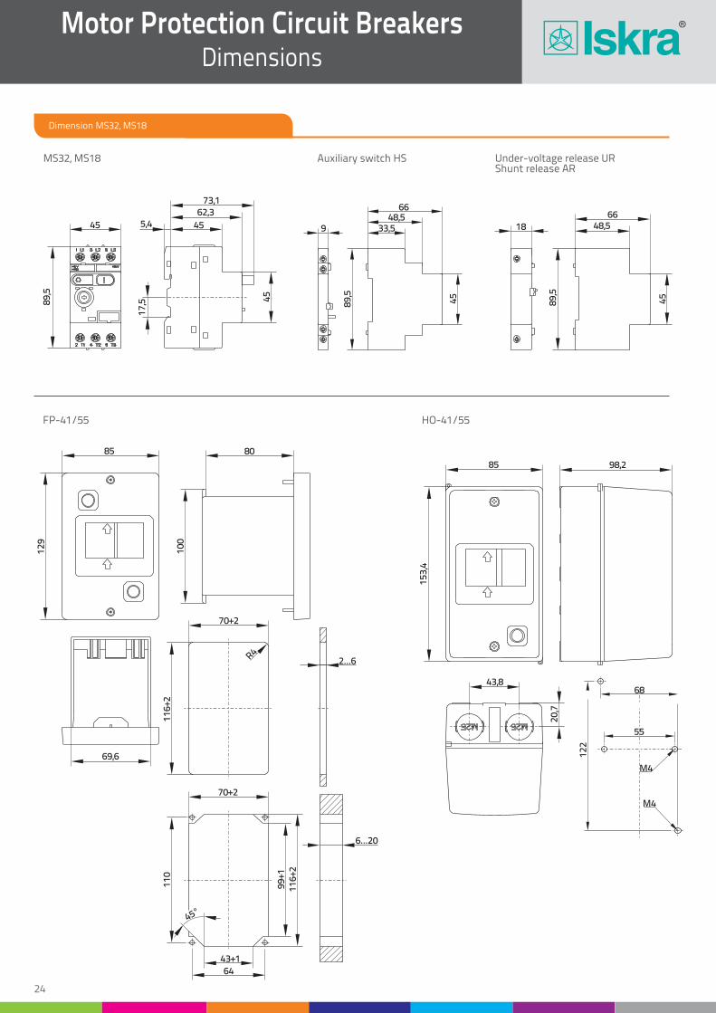
Dimension MS32, MS18
Motor Protection Circuit BreakersDimensions
MS32, MS18 Auxiliary switch HS
HO-41/55FP-41/55
Under-voltage release URShunt release AR
M4
M4
68
55
12
2
85
15
3,4
98,2
20
,7
43,8
85 80
69,6
12
9
10
0
18
6648,5
45
89
,5
6648,5
33,59
89
,5
45
45
73,162,3
455,4
17
,5 45
89
,5
70+2
11
6+2
2...6
70+2
45°
11
0
43+1
64
99
+11
16
+2
6...20
R4
24

Motor Protection Circuit BreakersDimensions
25
Dimension MS32, MS18
MS25 Auxiliary switch PS
O-41/55 CP-41/55
9 26,5
41,5
77
80
45
80 95,5
13
5
39
18
,5
12
9
85 80
70
45
80
35
45
83
73,5
4341
05
60
55
M4
M4