MOTOR CIRCUIT ANALYSIS TESTING
50
MOTOR CIRCUIT ANALYSIS TESTING AT WATERSURE USING ALLTEST PRO 5 ANALYSER. 1 • TO UNDERSTAND TRUE CONDITION OF PLANT CRITICAL MOTORS. • TO REPLACE/OVERHAUL MOTORS BEFORE CATASTROPHIC FAILURE OCCURS. • TO HELP ENSURE MOTOR AND PLANT RELIABILITY INTO THE FUTURE AT WATERSURE.
Transcript of MOTOR CIRCUIT ANALYSIS TESTING
MOTOR CIRCUIT ANALYSIS TESTING AT WATERSURE USING ALLTEST PRO 5
ANALYSER.
1
• TO UNDERSTAND TRUE CONDITION OF PLANT CRITICAL MOTORS.
• TO REPLACE/OVERHAUL MOTORS BEFORE CATASTROPHIC FAILURE OCCURS.
• TO HELP ENSURE MOTOR AND PLANT RELIABILITY INTO THE FUTURE AT WATERSURE.
2
• Low insulation resistance
• Overheating
• Contamination
• Moisture ingress
• High vibration
• Rotor failure
• Over current
• Bearing failure
COMMON CAUSES OF ELECTRIC MOTOR FAILURE

POSSIBLE CAUSES OF MOTOR FAILURE INTO THE FUTURE AT WATERSURE:
• Motor winding deterioration due to salt air contamination (causing breakdown of winding insulation and eventually causing turn to turn, coil to coil and phase to phase short circuit)
• Loose connections causing overheating of cables. • Corroded connections due to moisture from water ingress or condensation. • Collapsed bearing due to lack of lubrication, incorrect installation or high load. This can
cause rotor to rub on stator and destroy windings. • Polyamide cage in cylindrical roller bearings (ABB motors built in India are likely to have
polyamide or plastic cages in there roller bearings). Belt driven loads such as centrifuge primary motor and Backwash air blowers are prone to bearing failure if inadequate lubrication (due to high radial load and possibility of polyamide cage especially in 2 pole motors).
• NDE bearing spinning in housing causing looseness. Eventually rotor will rub on stator and short circuit stator (more likely in small motors with aluminum frame).
• Stator eccentricity from soft foot. This causes windings to vibrate at 2 x line frequency and is very bad for winding insulation. The vibration is at 2 X line Hz due to maximum magnetic field strength occurs 2 x per cycle.
• Motor running above full load current of motor on nameplate causing overheating• Cracked rotor bars/shorting ring could be a failure mode into the future. This is caused by
high amount of stop starts overheating rotor bars and eventually causing rotor bars to crack (will only happen if motors are DOL starting and have many stop/start cycles).
3
MOTOR CIRCUIT ANALSYIS TESTS CAN HIGHLIGHT:• Turn to turn short inside coil
• Short circuit between coils on same phase
• Short circuit between phases
• Short circuit to earth
• Loose or corroded connections in motor or MCC panel
• Contaminated or overheated windings
• Incorrectly configured terminal strip (if testing at motor)
• Rotor condition/cracked shorting ring or rotor bars (dynamic tests for rotor condition)
4
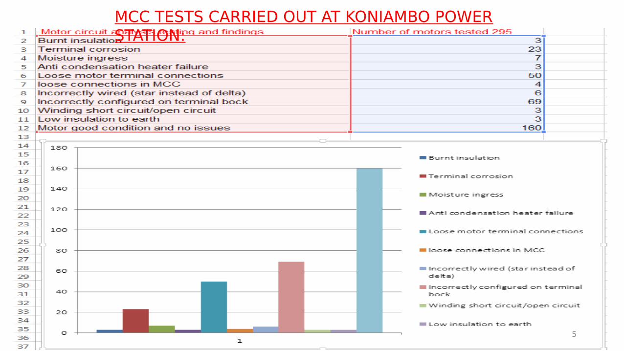
MCC TESTS CARRIED OUT AT KONIAMBO POWER STATION:
5

COMPARING MOTOR DIAGNOSTIC TECHNOLIGIES:
6
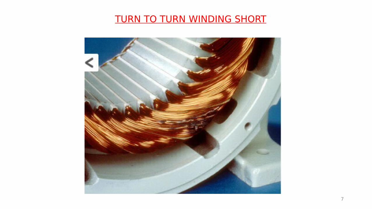
TURN TO TURN WINDING SHORT
7

COIL TO COIL WINDING SHORT:
8

PHASE TO PHASE WINDING SHORT:
9

WINDING SHORTED IN STATOR SLOT:
10
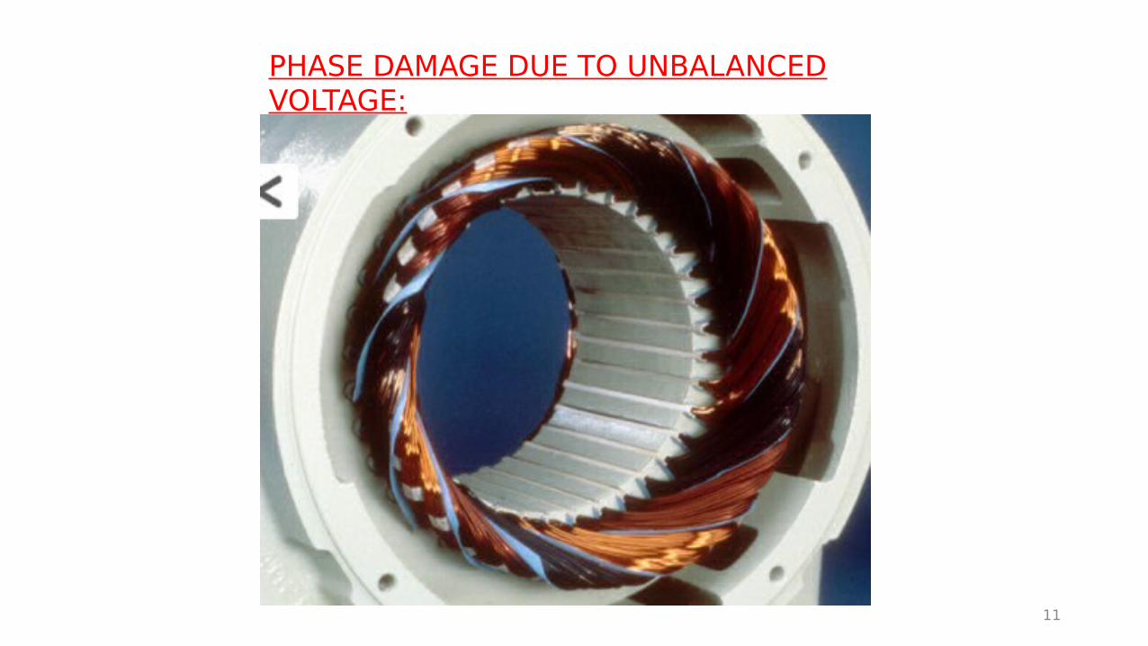
PHASE DAMAGE DUE TO UNBALANCED VOLTAGE:
11
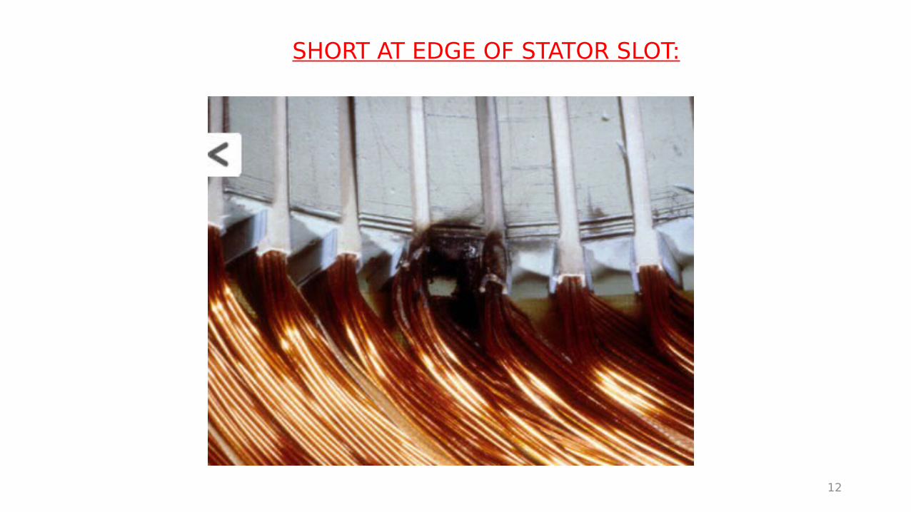
SHORT AT EDGE OF STATOR SLOT:
12
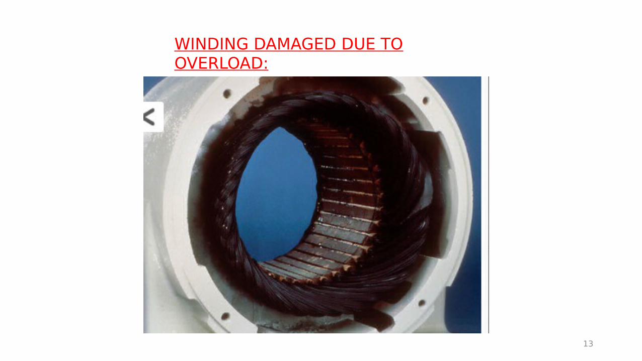
WINDING DAMAGED DUE TO OVERLOAD:
13
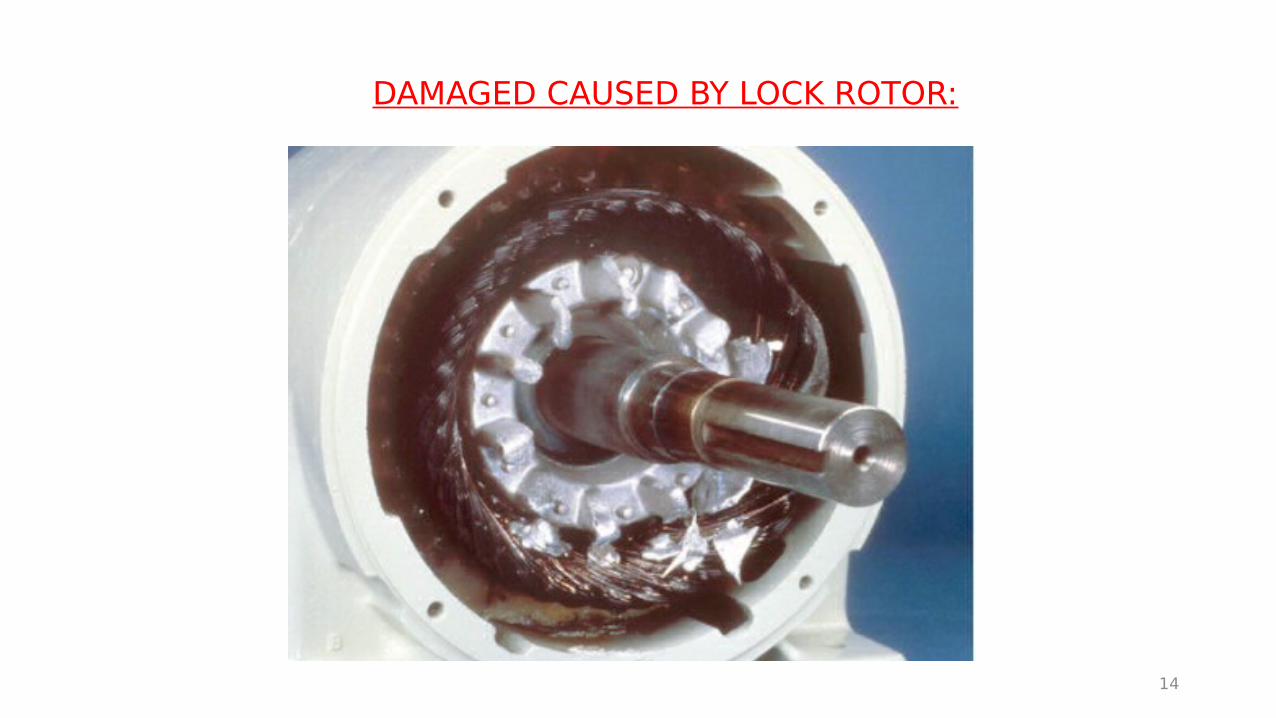
DAMAGED CAUSED BY LOCK ROTOR:
14

15
ALLTEST PRO 5 MOTOR ANALYSER

16
• Resistance
• Impedance
• Inductance
• Contamination (DF)
• Phase angle
• Current/frequency (I/F)
• Test value static (TVS)
• Dynamic test
• Insulation resistance
ALL-TEST PRO 5 TESTS THAT CAN BE CARRIED OUT

17
ALL TESTS PR0 5 TESTS AND TOLERANCES
MCA RESISTANCE TEST(MEASURED IN OHMS):
• It is the simple DC resistance of the circuit. If imbalance is found, it could mean loose connection at back of MCC, motor j/box or soldered coil connections inside motor.
• This test is very important due to the formula power (or heat) in watts = current squared x resistance. If you had a 0.1 ohm resistance across a connection in a circuit drawing 100 amps, your heat generated would be 100 x100 x 0.1 = 1000 watts. That is why we have burnt cables get burnt and fires occur in mcc’s.
• Values can be effected by induced voltages from live cables nearby. Need to check at motor to confirm.
18

Resistance imbalance on a water pump using all-test pro 4
19

Loose connection causing overheated supply lead to motor
20
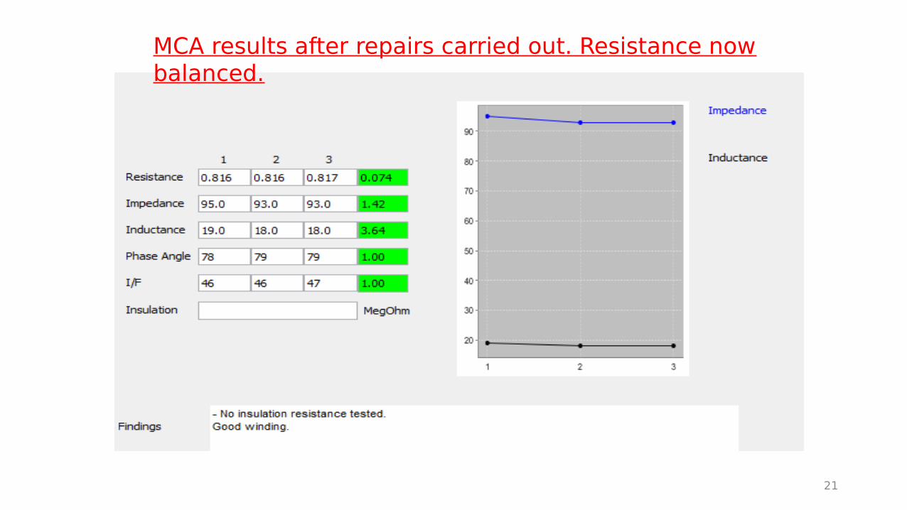
MCA results after repairs carried out. Resistance now balanced.
21
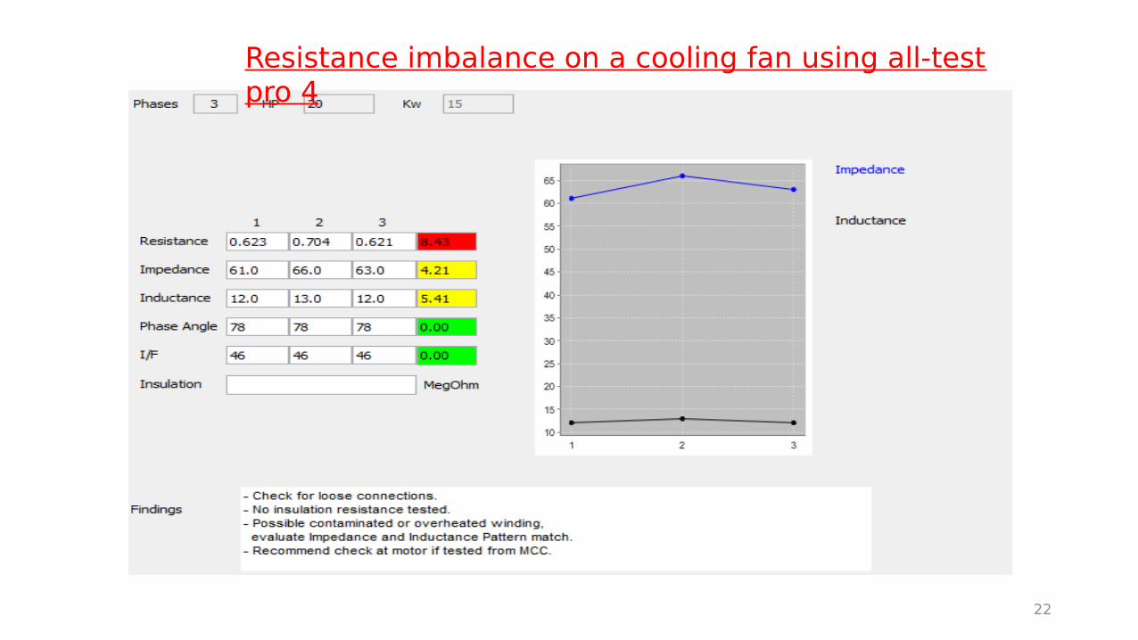
Resistance imbalance on a cooling fan using all-test pro 4
22
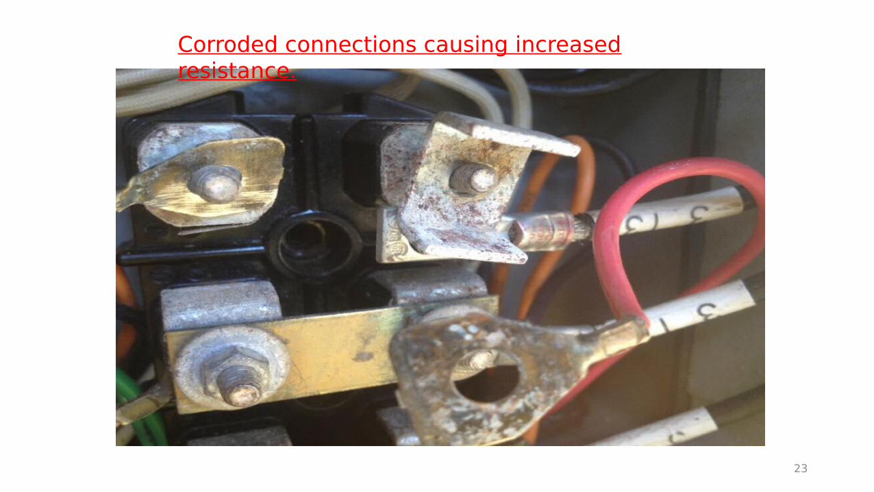
Corroded connections causing increased resistance.
23
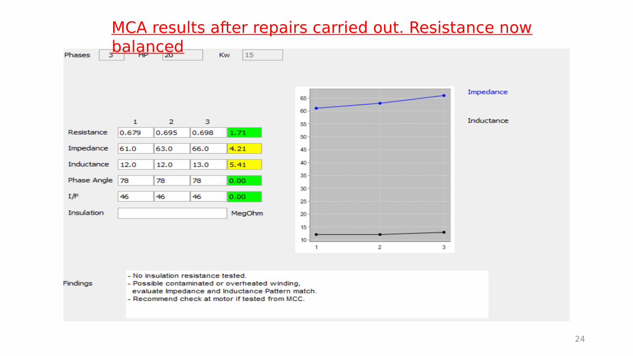
MCA results after repairs carried out. Resistance now balanced
24
25
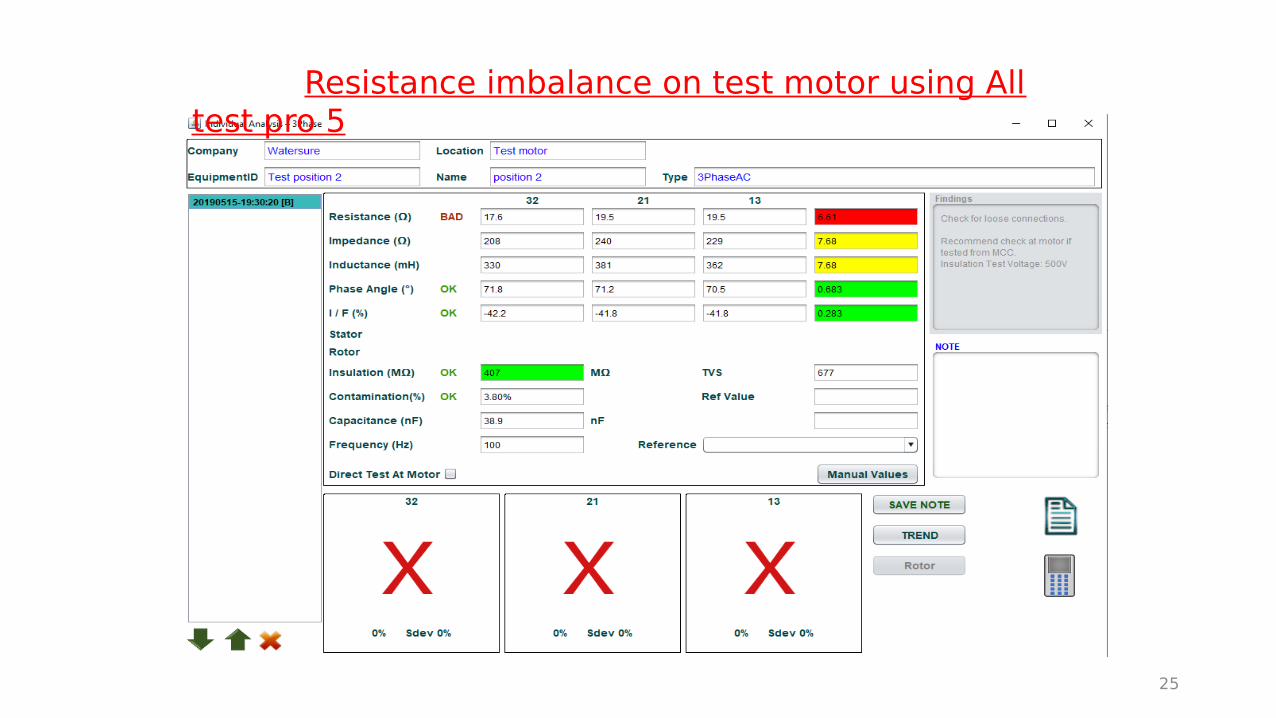
Resistance imbalance on test motor using All test pro 5
26
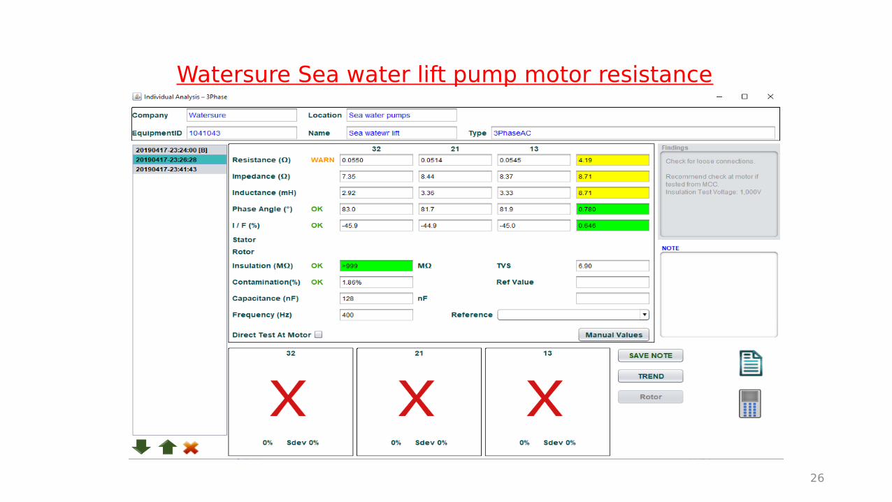
Watersure Sea water lift pump motor resistance imbalance
Resistance imbalance of 4.69 %
27
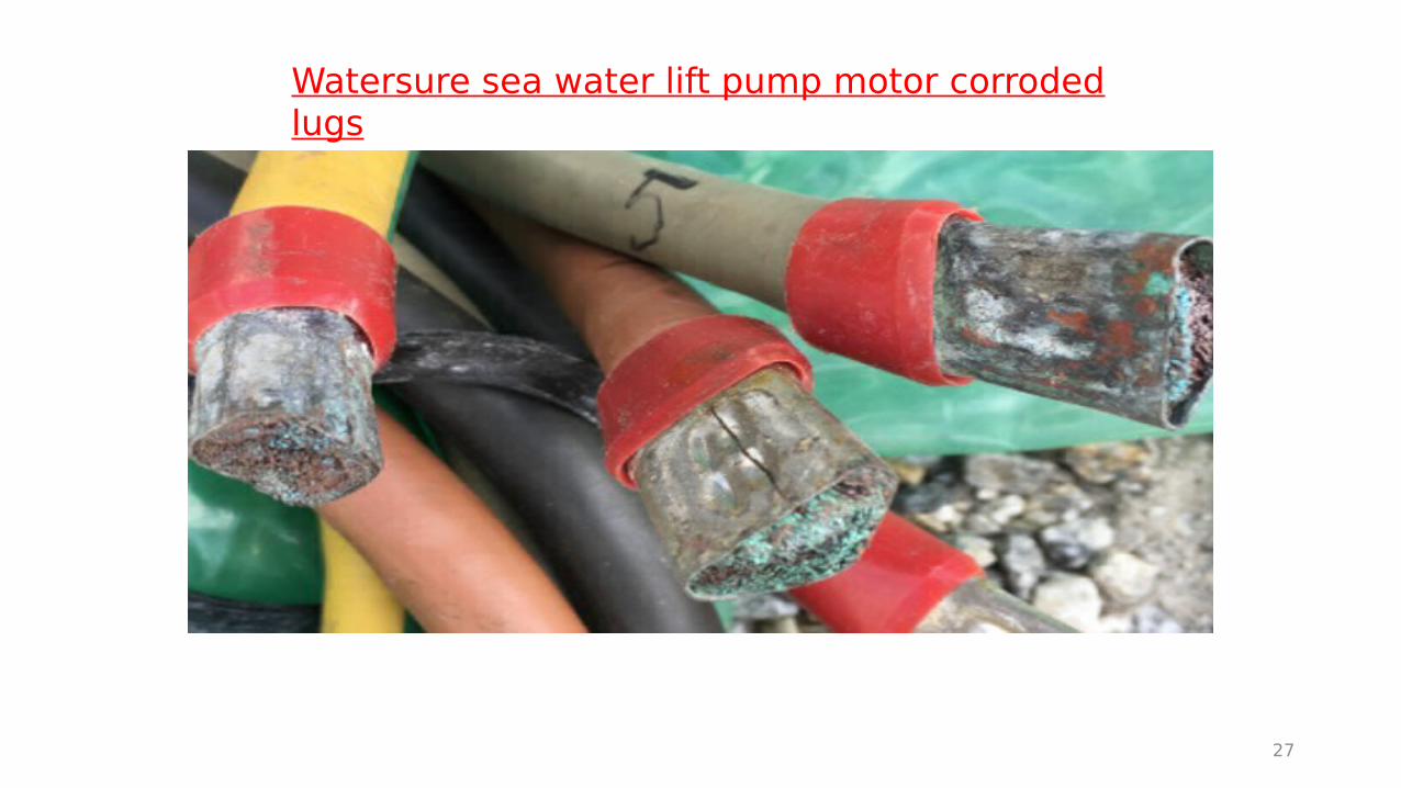
Watersure sea water lift pump motor corroded lugs
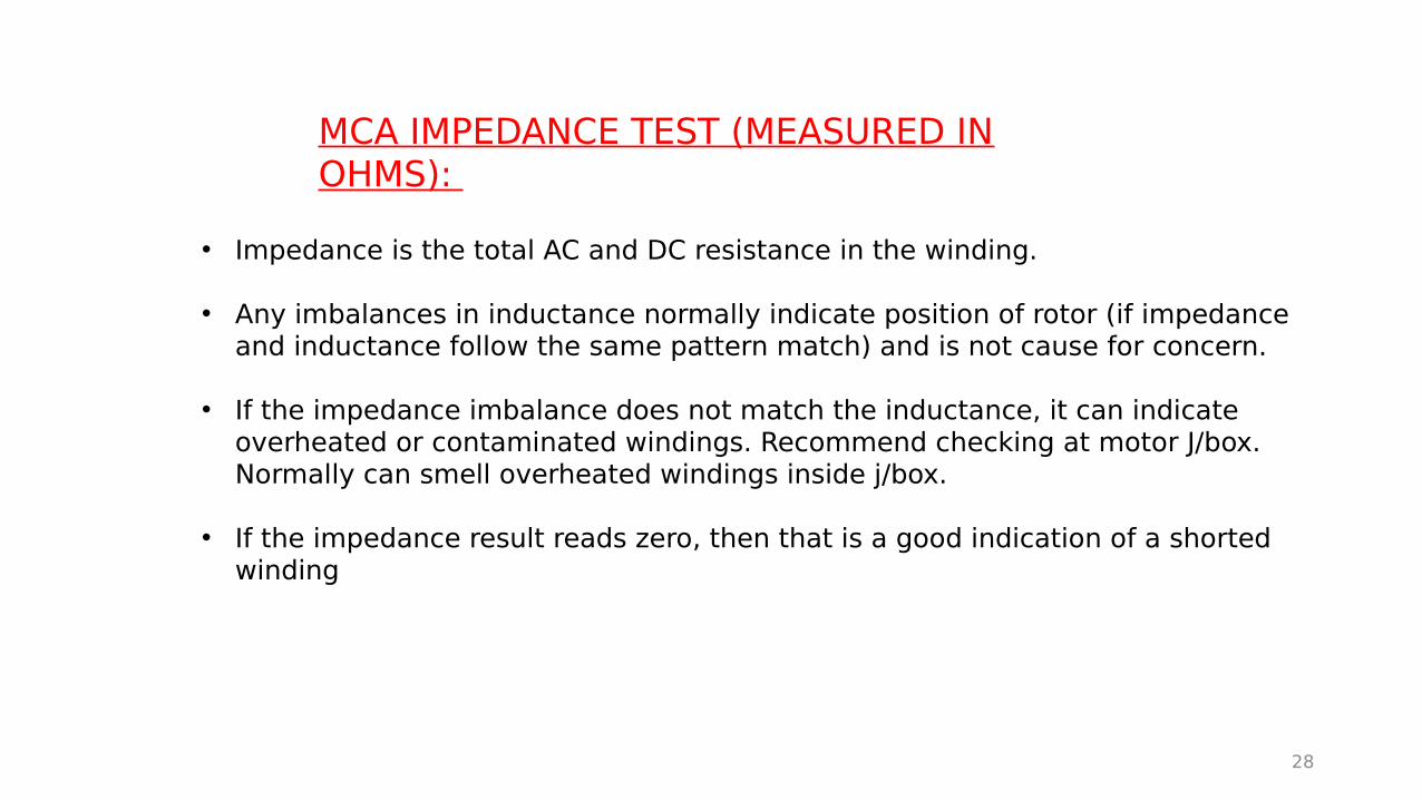
MCA IMPEDANCE TEST (MEASURED IN OHMS):
• Impedance is the total AC and DC resistance in the winding.
• Any imbalances in inductance normally indicate position of rotor (if impedance and inductance follow the same pattern match) and is not cause for concern.
• If the impedance imbalance does not match the inductance, it can indicate overheated or contaminated windings. Recommend checking at motor J/box. Normally can smell overheated windings inside j/box.
• If the impedance result reads zero, then that is a good indication of a shorted winding
28

Indication of contaminated or overheated windings using All-test pro 4
Different pattern match
29

INDUCTANCE (MEASURE IN HENRIES)
• Inductance measurement is the indicator of the magnetic strength of windings.
• If the inductance imbalance is high, but impedance values are normal, it can indicate shorted winding.
• Will show big imbalance if windings are shorted.
• If pattern match is the same as impedance, then it is the position of the rotor causing this and is not a problem.
30
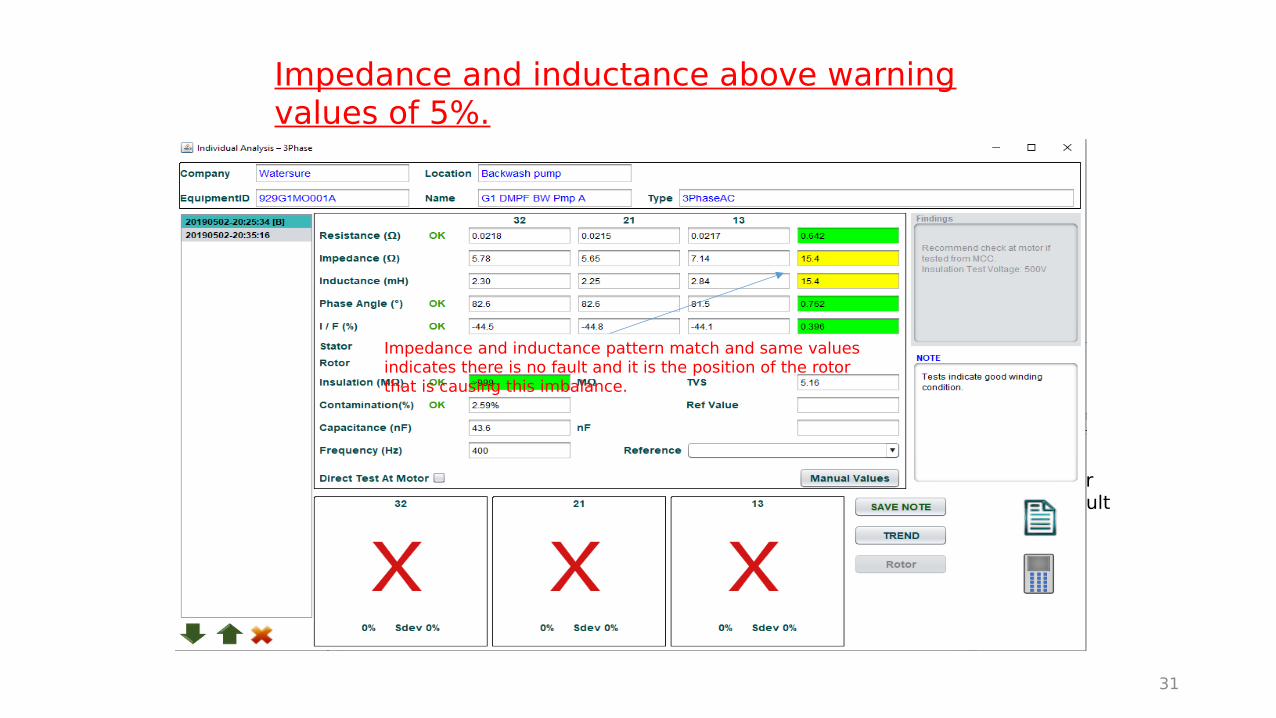
Impedance and inductance above warning values of 5%.
31
Values follow same pattern match and value indicating rotor position and not a fault
Impedance and inductance pattern match and same values indicates there is no fault and it is the position of the rotor that is causing this imbalance.
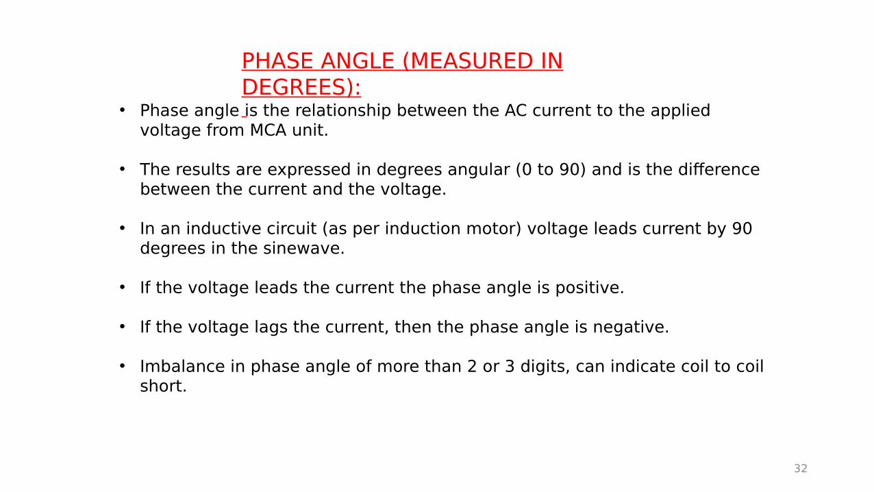
• Phase angle is the relationship between the AC current to the applied voltage from MCA unit.
• The results are expressed in degrees angular (0 to 90) and is the difference between the current and the voltage.
• In an inductive circuit (as per induction motor) voltage leads current by 90 degrees in the sinewave.
• If the voltage leads the current the phase angle is positive.
• If the voltage lags the current, then the phase angle is negative.
• Imbalance in phase angle of more than 2 or 3 digits, can indicate coil to coil short.
PHASE ANGLE (MEASURED IN DEGREES):
32

33
Stream 2 CIP pump A phase angle imbalance

I/F (CURRENT/FREQUENCY) MEASURED IN PERCENTAGE:
• Low voltage AC signal is injected into windings at a specific frequency and current is measured. The Hz is then doubled and current is measured.
• The I/F reading is ratio of the current at doubled frequency, compared to original frequency.
• An imbalance of more than 2 digits indicates possibility of phase to phase short. If the motor trips on startup then it is usually a phase to phase short or short to earth fault.
• A motor can have a good insulation resistance to earth (as per typical electricians test with megger), but still trip due to internal phase to phase fault.
• Phase to phase fault have potential to draw large currents and should trip motor out on overcurrent.
34

35
Test motor I/F (and phase anle) imbalance
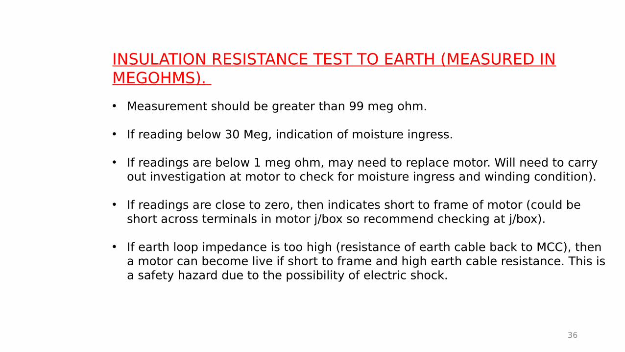
INSULATION RESISTANCE TEST TO EARTH (MEASURED IN MEGOHMS).
• Measurement should be greater than 99 meg ohm.
• If reading below 30 Meg, indication of moisture ingress.
• If readings are below 1 meg ohm, may need to replace motor. Will need to carry out investigation at motor to check for moisture ingress and winding condition).
• If readings are close to zero, then indicates short to frame of motor (could be short across terminals in motor j/box so recommend checking at j/box).
• If earth loop impedance is too high (resistance of earth cable back to MCC), then a motor can become live if short to frame and high earth cable resistance. This is a safety hazard due to the possibility of electric shock.
36

37
Test motor low insulation resistance and high contamination

Hydraulic pump motor earth fault with all-test pro 4.
38

Motor junction box full of watered down grease from NDE bearing.
39
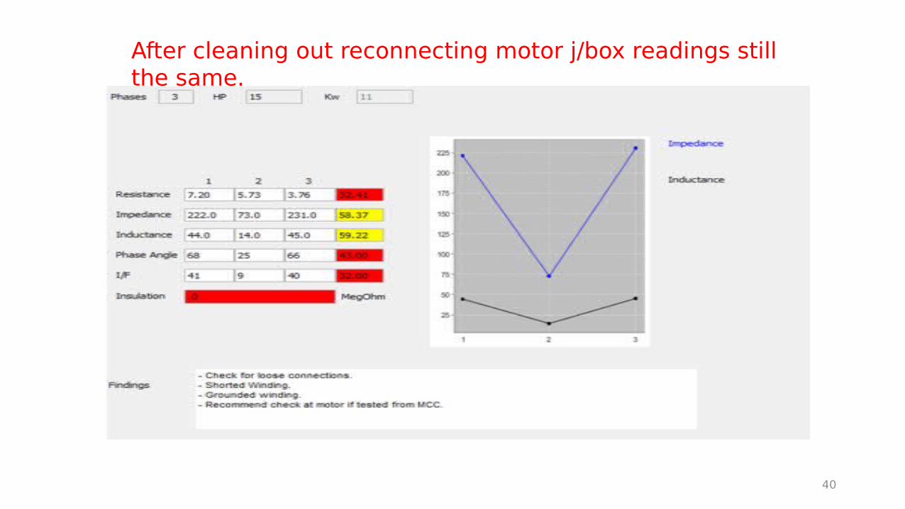
After cleaning out reconnecting motor j/box readings still the same.
40
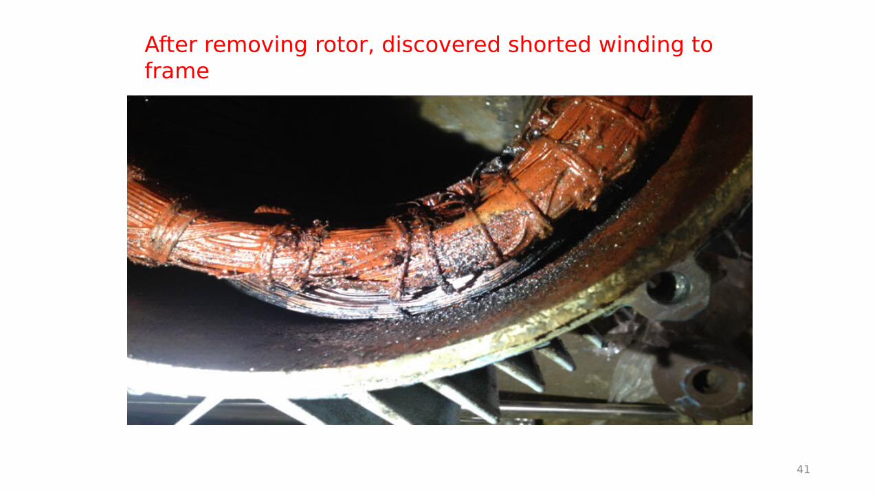
After removing rotor, discovered shorted winding to frame
41
42
CONTAMINATION (DISSIPATION FACTOR)
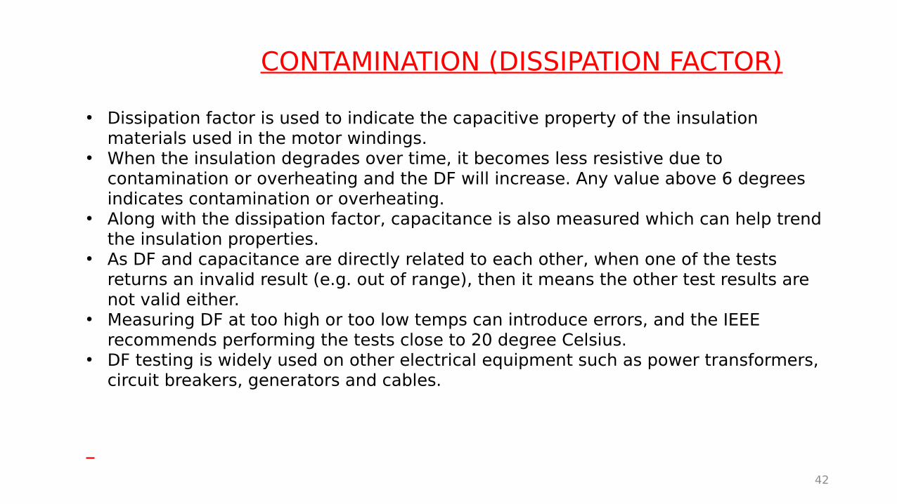
• Dissipation factor is used to indicate the capacitive property of the insulation materials used in the motor windings.
• When the insulation degrades over time, it becomes less resistive due to contamination or overheating and the DF will increase. Any value above 6 degrees indicates contamination or overheating.
• Along with the dissipation factor, capacitance is also measured which can help trend the insulation properties.
• As DF and capacitance are directly related to each other, when one of the tests returns an invalid result (e.g. out of range), then it means the other test results are not valid either.
• Measuring DF at too high or too low temps can introduce errors, and the IEEE recommends performing the tests close to 20 degree Celsius.
• DF testing is widely used on other electrical equipment such as power transformers, circuit breakers, generators and cables.

43
Example of low insulation resistance and high dissipation factorLow insulation resistance combined high dissipation factor is a strong indicator of seriously degraded winding insulation.
44
CAPACITANCE, TVS AND RVS
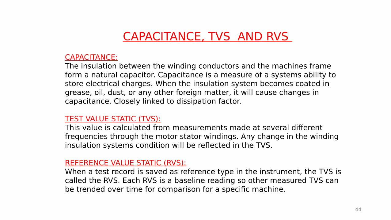
CAPACITANCE:The insulation between the winding conductors and the machines frame form a natural capacitor. Capacitance is a measure of a systems ability to store electrical charges. When the insulation system becomes coated in grease, oil, dust, or any other foreign matter, it will cause changes in capacitance. Closely linked to dissipation factor.
TEST VALUE STATIC (TVS): This value is calculated from measurements made at several different frequencies through the motor stator windings. Any change in the winding insulation systems condition will be reflected in the TVS.
REFERENCE VALUE STATIC (RVS):When a test record is saved as reference type in the instrument, the TVS is called the RVS. Each RVS is a baseline reading so other measured TVS can be trended over time for comparison for a specific machine.
45
DYNAMIC TESTING TO HIGHLIGHT STATOR AND ROTOR FAULTS.
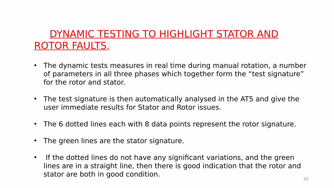
• The dynamic tests measures in real time during manual rotation, a number of parameters in all three phases which together form the “test signature” for the rotor and stator.
• The test signature is then automatically analysed in the AT5 and give the user immediate results for Stator and Rotor issues.
• The 6 dotted lines each with 8 data points represent the rotor signature.
• The green lines are the stator signature.
• If the dotted lines do not have any significant variations, and the green lines are in a straight line, then there is good indication that the rotor and stator are both in good condition.

46
Dynamic tests can confirm stator issues and highlight rotor issues.
With a dynamic test, the rotor is manually rotated and a signature of both the rotor and stator are provided to highlight any faults with either rotor or stator
47
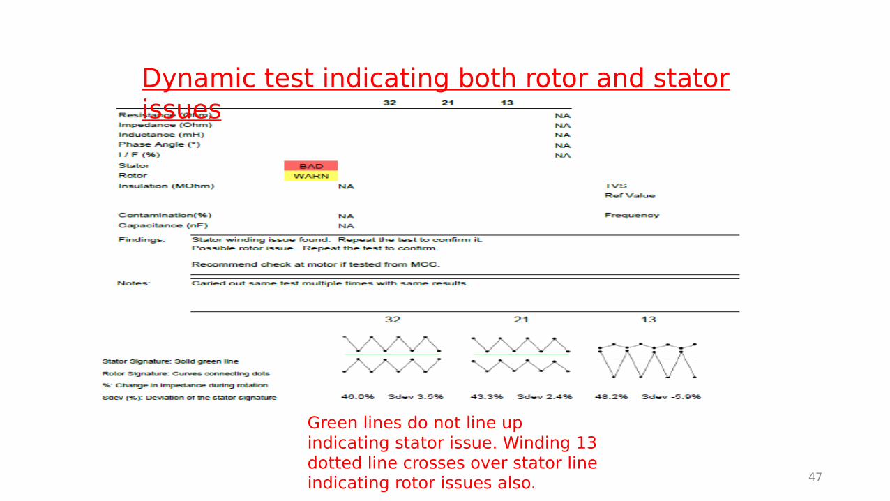
Dynamic test indicating both rotor and stator issues
Green lines do not line up indicating stator issue. Winding 13 dotted line crosses over stator line indicating rotor issues also.

48
Dynamic tests indicating both rotor and stator are good.
Green lines and dotted lines balanced indicating good stator and rotor.

IMPORTANT THINGS TO BE AWARE OF WHEN USING ALL TEST PRO 5:• If motor is moving due to fan or pump being driven by air flow from wind, or bypassing
valve causing pump to rotate backwards, then a voltage will be induced into windings. This will give incorrect readings. Any motor that has an indication of fault, ensure that it is not rotating.
• If tests carried out at MCC indicate a fault, repeat test at least 2 more times to check for repeatability. If imbalance still exists then retest at motor j/box.
• If motor still indicates winding short when tested at j/box do test 2 more times to check for repeatability. Then if possible, you will need to do dynamic test to confirm stator issues and any rotor issues.
• If resistance imbalance is significant, then all the other tests will be unreliable. Need to address the resistance issue before condemning the motor.
• Never condemn a motor without carrying out the steps above!
• Always disconnect outgoing cables from VSD drives to protect electronics inside VSD (if doing test from panel) or disconnect at motor j/box if doing test at motor.
49
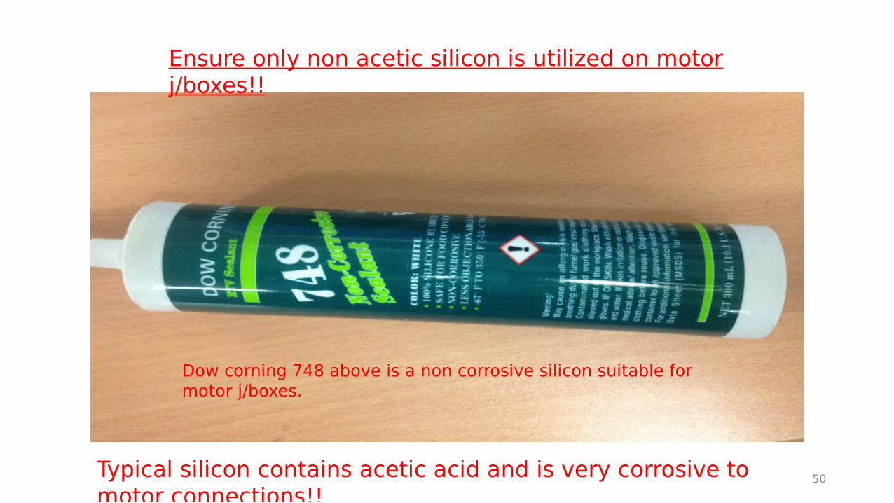
Ensure only non acetic silicon is utilized on motor j/boxes!!
Typical silicon contains acetic acid and is very corrosive to motor connections!!
Dow corning 748 above is a non corrosive silicon suitable for motor j/boxes.
50