MOTOMAN-GP50 SUPPLEMENTAL INSTRUCTIONS (F00) · Introduction This supplemental instruction manual...
15
MANUAL NO. HW1485886 MOTOMAN-GP50 SUPPLEMENTAL INSTRUCTIONS TYPE: YR-1-06VX50-F00 (FOR FOOD GRADE GREASE) Upon receipt of the product and prior to initial operation, read these instructions thoroughly, and retain for future reference. MOTOMAN INSTRUCTIONS MOTOMAN-GP50,GP35L INSTRUCTIONS MOTOMAN-GP50,GP35L SUPPLEMENTAL INSTRUCTIONS YRC1000 INSTRUCTIONS YRC1000 OPERATOR’S MANUAL (GENERAL) (SUBJECT SPECIFIC) YRC1000 MAINTENANCE MANUAL YRC1000 ALARM CODES (MAJOR ALARMS) (MINOR ALARMS) 1/15 187106-1CD 0
Transcript of MOTOMAN-GP50 SUPPLEMENTAL INSTRUCTIONS (F00) · Introduction This supplemental instruction manual...
MANUAL NO.
HW1485886
MOTOMAN-GP50SUPPLEMENTAL INSTRUCTIONS
TYPE:YR-1-06VX50-F00 (FOR FOOD GRADE GREASE)
Upon receipt of the product and prior to initial operation, read these instructions thoroughly, and retain for future reference.
MOTOMAN INSTRUCTIONS
MOTOMAN-GP50,GP35L INSTRUCTIONSMOTOMAN-GP50,GP35L SUPPLEMENTAL INSTRUCTIONSYRC1000 INSTRUCTIONSYRC1000 OPERATOR’S MANUAL (GENERAL) (SUBJECT SPECIFIC)YRC1000 MAINTENANCE MANUAL YRC1000 ALARM CODES (MAJOR ALARMS) (MINOR ALARMS)
1/15
187106-1CD0

2
HW1485886
HW1485886
IntroductionThis supplemental instruction manual describes MOTOMAN-GP50 for food grade grease (YR-1-06VX50-F00).
Point of DifferenceThe YR-1-06VX50-F00 differ from the YR-1-06VX50-A00 in the following points:
• Grease for gear and each axis speed reducer
• IP65 for the IEC protection class of the manipulator
This manual differs from “MOTOMAN-GP50,GP35L INSTRUCTIONS” (Manual No. HW1484659) in the following points.
• 3.4 Location
• 3.5 Notes on Dust-Poof/Water-Proof Specifications
• 5.1 Basic Specifications
• 5.4.3 Stopping Distance and Time for Stop Category 0: S-, L- and U-Axes
• 5.4.4.2 Stopping Distance and Time for Stop Category 1:S-axis (YR-1-06VX50-F00)
• 5.4.4.3 Stopping Distance and Time for Stop Category 1: L-axis (YR-1-06VX50-F00)
• 5.4.4.4 Stopping Distance and Time for Stop Category 1:U-axis (YR-1-06VX50-F00)
• 9.1 Inspection Schedule
• 9.4 Notes on Grease Replenishment/Exchange Procedures
• 10 Recommended Spare Parts
2/15

3.4 Location
3
HW1485886
HW1485886
3.4 Location
When installing a manipulator, it is necessary to satisfy the following environmental conditions:
• Ambient temperature: + 15°C to + 45°C
• Humidity: 20% to 80%RH
• Free from dust, soot, or oil
• Free from corrosive gas or liquid, or explosive gas or liquid
• Free from excessive vibration (Vibration acceleration: 4.9 m/s2
[0.5 G] or less)
• Free from large electrical noise (plasma)
• Free from the strong magnetic field
• Altitude: 1000 m or less
• Flatness for installation: 0.5 mm or less
NOTEWhen the operation is started after the manipulator has been out of operation for a long period, the alarm may occur since the friction torque of the drive unit is large.If the alarm occurs, perform the break-in for few minutes.
3/15

3.5 Notes on Dust-Poof/Water-Proof Specifications
4
HW1485886
HW1485886
3.5 Notes on Dust-Poof/Water-Proof Specifications
The YR-1-06VX50-F00 conform to:
IP67 for the wrist part IP65 for the main part of the manipulator
However, the following precautions must be observed:
• Do not use the following liquids, because the rubber parts of the manipulator (gasket, oil seal, O-ring, etc.) may be deteriorated or corroded:
• Organic solvent
• Chlorine-based cutting fluid
• Amine-based cleaning fluid
• Corrosive substances such as acids, alkalis,or liquids/solutions causing rust
• Other liquids/solutions to which nitrile-butadiene rubber (NBR) is not resistant
• After removing a gasket for parts replacement or maintenance/inspection, make sure to replace the gasket with a new one.
• Do not use cutting fluid or cleaning fluid which contains unknown chemical substances.
NOTE
< Definition of IP (protection class) >
• Definition of IP67
IP6□: Protection from the entry of dust
IP□7: Protection from immersion in water with being submerged for a specified duration and pressure
• Definition of IP65
IP6□: Protection from the entry of dust
IP□5: Protection from water that is directly sprayed from any direction
4/15

5.1 Basic Specifications
5
HW1485886
HW1485886
5.1 Basic SpecificationsTable 5-1: Basic Specifications (YR-1-06VX50-F00)1)
1 SI units are used in this table. However, gravitational unit is used in ( ).
TypeYR-1-06VX50-F00
Item
Structure Vertically articulated
Degree of freedom 6
Payload Wrist part 50 kg
U-arm 10 kg
Repeatability2)
2 Conformed to ISO9283
±0.07 mm
Range of Motion S-Axis (turning) -180° - +180°L-Axis (lower arm) -90° - +135°U-Axis (upper arm) -80° - +206°R-Axis (wrist roll) -360° - +360°B-Axis (wrist pitch/yaw) -125° - +125°T-Axis (wrist twist) -360° - +360°
Maximum Speed S-Axis 3.14 rad/s, 180°/sL-Axis 3.11 rad/s, 178°/sU-Axis 3.11 rad/s, 178°/sR-Axis 2.61 rad/s, 150°/sB-Axis 2.61 rad/s, 150°/sT-Axis 3.49 rad/s, 200°/s
Allowable Moment3)
3 Refer to chapter 6.1 “Allowable Wrist Load” for details on the allowable moment and the allowable inertia.
R-Axis 216 N•m (22 kgf•m)
B-Axis 216 N•m (22 kgf•m)
T-Axis 147 N•m (15 kgf•m)
Allowable Inertia(GD2/4)3)
R-Axis 28 kg•m2
B-Axis 28 kg•m2
T-Axis 11 kg•m2
Approx. Mass 570 kg
Protective enclosure Body: IP65 Wrist part: IP67
Mounting method Floor-mounted
Power Capacity 4.5 kVA
Applicable controller YRC1000
Equivalent continuous sound pressure level4)
4 Conformed to equivalent continuous A-weighted sound pressure level measured in accordance withISO11201 (EN31201).
1, Measurement is carried out when the maximum load is mounted to the manipulator and operated in the maximum speed. 2, Measurement is carried out: -between 1.2 m and 1.5 m above the ground. -400 mm away from the P-point maximum envelope.
72 dB or less
5/15

6
HW1485886
HW1485886
5.4.3 Stopping Distance and Time for Stop Category 0: S-, L- and U-Axes
Measurement Conditions
• Load: Maximum load
• Speed: Maximum speed
• Posture: Maximum inertia generation posture
Table 5-3: YR-1-06VX50-F00
Axis Stopping distance (deg) Stopping time (sec)
S-axis 26.5 0.347
L-axis 39.6 0.562
U-axis 27.3 0.313
6/15

7
HW1485886
HW1485886
5.4.4.2 Stopping Distance and Time for Stop Category 1: S-axis (YR-1-06VX50-F00)
0.0
0.1
0.2
0.3
0.4
0.5
0.6
0.7
0.8
0 50 100 150 200
Sto
ppin
g tim
e[se
c]
Speed[deg/s]
Extension 100%
Load100% Load66% Load33%
0
10
20
30
40
50
60
70
80
0 50 100 150 200
Sto
ppin
g di
stan
ce[d
eg]
Speed[deg/s]
Extension 100%
Load100% Load66% Load33%
0.0
0.1
0.2
0.3
0.4
0.5
0.6
0.7
0.8
0 50 100 150 200
Sto
ppin
g tim
e[se
c]
Speed[deg/s]
Extension 66%
Load100% Load66% Load33%
0
10
20
30
40
50
60
70
80
0 50 100 150 200
Sto
ppin
g di
stan
ce[d
eg]
Speed[deg/s]
Extension 66%
Load100% Load66% Load33%
0.0
0.1
0.2
0.3
0.4
0.5
0.6
0.7
0.8
0 50 100 150 200
Sto
ppin
g tim
e[se
c]
Speed[deg/s]
Extension 33%
Load100% Load66% Load33%
0
10
20
30
40
50
60
70
80
0 50 100 150 200
Sto
ppin
g di
stan
ce[d
eg]
Speed[deg/s]
Extension 33%
Load100% Load66% Load33%
7/15
8
HW1485886
HW1485886
5.4.4.3 Stopping Distance and Time for Stop Category 1: L-axis (YR-1-06VX50-F00)
0
10
20
30
40
50
60
70
80
0 50 100 150 200
Sto
ppin
g di
stan
ce[d
eg]
Speed[deg/s]
Extension 100%
Load100% Load66% Load33%
0.0
0.1
0.2
0.3
0.4
0.5
0.6
0.7
0.8
0.9
0 50 100 150 200
Sto
ppin
g tim
e[se
c]
Speed[deg/s]
Extension 100%
Load100% Load66% Load33%
0
10
20
30
40
50
60
70
80
0 50 100 150 200
Sto
ppin
g di
stan
ce[d
eg]
Speed[deg/s]
Extension 66%
Load100% Load66% Load33%
0.0
0.1
0.2
0.3
0.4
0.5
0.6
0.7
0.8
0.9
0 50 100 150 200
Sto
ppin
g tim
e[se
c]
Speed[deg/s]
Extension 66%
Load100% Load66% Load33%
0
10
20
30
40
50
60
70
80
0 50 100 150 200
Sto
ppin
g di
stan
ce[d
eg]
Speed[deg/s]
Extension 33%
Load100% Load66% Load33%
0.0
0.1
0.2
0.3
0.4
0.5
0.6
0.7
0.8
0.9
0 50 100 150 200
Sto
ppin
g tim
e[se
c]
Speed[deg/s]
Extension 33%
Load100% Load66% Load33%
8/15
9
HW1485886
HW1485886
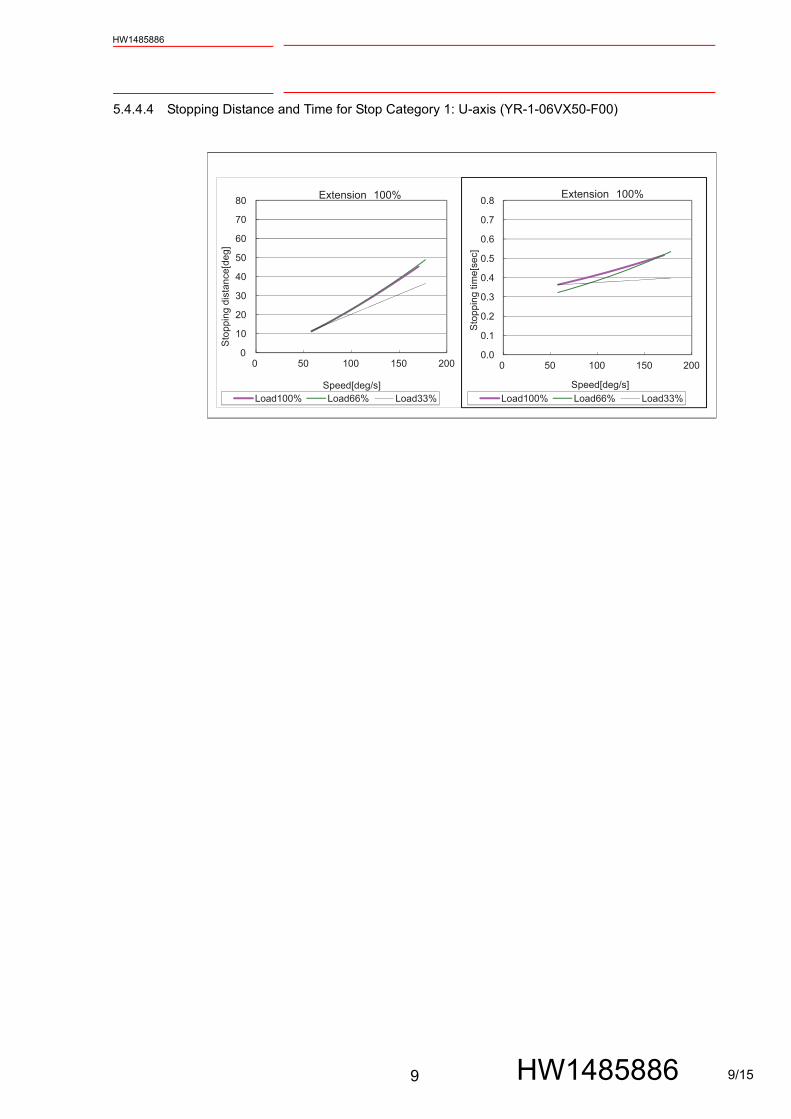
5.4.4.4 Stopping Distance and Time for Stop Category 1: U-axis (YR-1-06VX50-F00)
0
10
20
30
40
50
60
70
80
0 50 100 150 200
Sto
ppin
g di
stan
ce[d
eg]
Speed[deg/s]
Extension 100%
Load100% Load66% Load33%
0.0
0.1
0.2
0.3
0.4
0.5
0.6
0.7
0.8
0 50 100 150 200
Sto
ppin
g tim
e[se
c]
Speed[deg/s]
Extension 100%
Load100% Load66% Load33%
9/15
9.1 Inspection Schedule
10
HW1485886
HW1485886
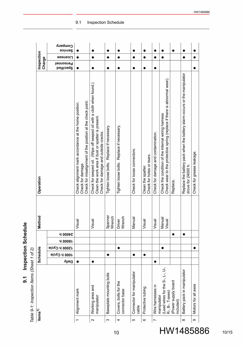
9.1
Insp
ecti
on
Sch
edu
le
Tabl
e 9
-1:
Insp
ect
ion
Ite
ms
(Sh
eet
1 o
f 2
)
Item
s1)S
ched
ule
Me
tho
dO
per
atio
nIn
spec
tio
n
Ch
arg
e
Daily
1000 h Cycle
12000 h Cycle
18000 h
24000 h
Specified Personnel
Licensee
Service Company
1A
lign
me
nt m
ark
•V
isua
lC
heck
alig
nmen
t mar
k ac
cord
anc
e at
the
hom
e p
ositi
on.
Ch
eck
for
dam
age.
Ch
eck
for
mis
alig
nmen
t of
the
posi
tion
at th
e c
hec
k p
oint
.
••
•
2W
ork
ing
area
and
m
ani
pul
ator
•V
isua
lC
hec
k fo
r se
epe
d oi
l. (
Wip
e o
ff se
epe
d oi
l with
a c
loth
whe
n fo
und.
)C
lean
the
wor
k ar
ea if
dus
t or
spa
tter
is p
rese
nt.
Ch
eck
for
dam
age
and
outs
ide
cra
cks.
••
•
3B
asep
late
mo
untin
g b
olts
•S
pann
er
Wre
nch
Tig
hten
loo
se b
olts
. R
epla
ce if
nec
essa
ry.
••
•4
Cov
ers,
bol
ts fo
r th
e co
nne
cto
r ba
se
•D
river
Wre
nch
Tig
hten
loo
se b
olts
. R
epla
ce if
nec
essa
ry.
••
•
5C
onn
ecto
r fo
r m
anip
ula
tor
cabl
e•
Ma
nua
lC
hec
k fo
r lo
ose
co
nnec
tors
.•
••
6P
rote
ctiv
e tu
bin
g•
Vis
ual
Cle
an t
he s
patt
er.
Ch
eck
for
hole
s o
r te
ars.
••
•7
Wire
har
ness
es in
m
ani
pul
ator
(Lea
d w
ires
for
the
S-,
L-,
U-,
R
-, B
-, T
-axe
s)(P
ow
er s
uppl
y b
oard
in
clu
ded
)
•V
isua
lC
hec
k fo
r da
mag
e an
d co
nta
min
atio
n.•
••
•M
anu
al
Vis
ual
Ch
eck
the
con
ditio
n o
f th
e in
tern
al w
iring
har
ness
Ch
eck
we
ar to
the
pro
tect
ive
sprin
g (r
epl
ace
if th
ere
is a
bno
rma
l wea
r).
••
•R
epl
ace
.•
8B
atte
ry p
ack
in m
anip
ula
tor
•R
epl
ace
the
bat
tery
pac
k w
hen
the
batte
ry a
larm
occ
urs
or
the
man
ipul
ator
dr
ove
for
240
00 h
.•
•9
Mo
tors
for
all
axes
•C
hec
k fo
r gr
ease
leak
age.
••
•
10/15

9.1 Inspection Schedule
11
HW1485886
HW1485886
10
Sp
eed
red
ucer
s fo
r al
l axe
s•
Gre
ase
Gun
Ch
eck
for
ma
lfunc
tion
. (R
epla
ce if
ne
cess
ary.
)R
epl
ace
gre
ase2
) (12
000
h cy
cle)
.•
•11
B-
and
T-ax
es g
ear
•G
rea
se G
unC
hec
k fo
r m
alfu
nctio
n.
(Rep
lace
if n
ece
ssar
y.)
Re
plac
e g
reas
e2) (
1200
0 h
cycl
e).
••
12
Ove
rhau
l•
•1
Ins
pect
ion
No
. cor
resp
ond
to
the
num
bers
in fi
g. 9
-1 "
Insp
ect
ion
Item
s (H
ome
pos
ition
figu
re)"
.2
For
the
grea
se, r
efer
to ta
ble
9-2
“In
spe
ctio
n P
art
s an
d G
reas
e U
sed”
.
Tabl
e 9
-2:
Insp
ect
ion
Pa
rts
and
Gre
ase
Use
d
No
.G
reas
e U
sed
Insp
ect
ed P
art
s
10,
11
CA
SS
IDA
gre
ase
EP
S00
Sp
eed
redu
cers
for
all a
xes
B-
and
T-a
xis
gear
s
Tabl
e 9
-1:
Insp
ect
ion
Ite
ms
(Sh
eet
2 o
f 2
)
Item
s1)S
ched
ule
Me
tho
dO
per
atio
nIn
spec
tio
n
Ch
arg
e
Daily
1000 h Cycle
12000 h Cycle
18000 h
24000 h
Specified Personnel
Licensee
Service Company
11/15

9.4 Notes on Grease Replenishment/Exchange Procedures
12
HW1485886
HW1485886
9.4 Notes on Grease Replenishment/Exchange Procedures
Where the following types of grease appear in the manual, they should be replaced as follows:
Gear and each axis speed reducerMolywhite RE No.00 to CASSIDA grease EPS00
Table 9-3: Amount of GreaseAxis to exchange grease Amount of grease
S-axis Approx. 2840 g
L-axis Approx. 1460 g
U-axis Approx. 660 g
R-axis Approx. 3150 g
B-, and T-axesB-, and T-axis gears
Approx. 1350 g
12/15

10 Recommended Spare Parts
13
HW1485886
HW1485886
10 Recommended Spare Parts
It is recommended to keep the parts and components in the following table in stock as spare parts for the YR-1-06VX50-F00.
To purchase lead wires of the wire harness or etc., check the order/manufacture no. and contact YASKAWA representative.
Product performance cannot be guaranteed when using spare parts from any company other than YASKAWA. The spare parts are ranked as follows:
• Rank A: Expendable and frequently replaced parts.
• Rank B: Parts for which replacement may be necessary as a result of frequent operation.
• Rank C: Drive unit.
NOTE For replacing parts in Rank B or Rank C, contact your YASKAWA representative.
Table 10-1: Recommend Spare Parts for the YR-1-06VX50-F00 (Sheet 1 of 2)
Rank PartsNo.
Name Type Manufacturer Qty QtyperUnit
Remarks
A 1 Grease CASSIDA greaseEPS00
YASKAWA Electric Corporation
19 kg -
A 2 Grease CASSIDA greaseEPS02
YASKAWA Electric Corporation
19 kg -
A 3 Liquid Gasket TB1206C ThreeBondCo., Ltd.
- -
B 4 Replacement Kit for S-Axis Speed Reducer 1)
HW1485086-A YASKAWA Electric Corporation
1 1 Speed reducer: HW1382898-AInput gear: HW0313741-1
B 5 Replacement Kit for L-Axis Speed Reducer 1)
HW1485871-A YASKAWA Electric Corporation
1 1 Speed reducer: HW9381465-BInput gear: HW9482771-A
B 6 Replacement Kit for U-Axis Speed Reducer 1)
HW1485872-A YASKAWA Electric Corporation
1 1 Speed reducer: HW0387753-AInput gear: HW0313740-1
B 7 Replacement Kit for R-Axis Speed Reducer 1)
HW1485873-A YASKAWA Electric Corporation
1 1 Speed reducer: HW0387754-A
B 8 Replacement Kit for B-Axis Speed Reducer 1)
HW1485874-A YASKAWA Electric Corporation
1 1 Speed reducer: HW0387737-B
13/15

10 Recommended Spare Parts
14
HW1485886
HW1485886
B 9 Replacement Kit for T-Axis Speed Reducer 1)
HW1485875-A YASKAWA Electric Corporation
1 1 Speed reducer: HW0389043-A
B 10 Wrist Unit HW1173743-C YASKAWA Electric Corporation
1 1
B 11 Internal Wiring Harness
HW1173704-A YASKAWA Electric Corporation
1 1
1 Replacement kit for the speed reducer includes the speed reducer and the gear described in the Remarks. For details of the replacement kit for the speed reducer, contact your YASKAWA representatives.
Table 10-1: Recommend Spare Parts for the YR-1-06VX50-F00 (Sheet 2 of 2)
Rank PartsNo.
Name Type Manufacturer Qty QtyperUnit
Remarks
14/15

HW1485886
C 2019 YASKAWA ELECTRIC CORPORATIONPublished by YASKAWA
MANUAL NO.
January 2019 19-01
MOTOMAN-GP50SUPPLEMENTAL INSTRUCTIONS
HEAD OFFICE2-1 Kurosakishiroishi, Yahatanishi-ku, Kitakyushu 806-0004, JapanPhone +81-93-645-7703 Fax +81-93-645-7802
100 Automation Way, Miamisburg, OH 45342, U.S.A. Phone +1-937-847-6200 Fax +1-937-847-6277
YASKAWA America Inc. (Motoman Robotics Division)
Yaskawastrasse 1, 85391 Allershausen, GermanyPhone +49-8166-90-100 Fax +49-8166-90-103
YASKAWA Europe GmbH Robotics Divsion )
Phone +82-2-784-7844 Fax +82-2-784-8495
151 Lorong Chuan, #04-02A, New Tech Park, Singapore 556741Phone +65-6282-3003 Fax +65-6289-3003
YASKAWA Electric (Singapore) PTE Ltd.
No7 Yongchang North Road, Beijing E&T Development Area China 100176Phone +86-10-6788-2858 Fax +86-10-6788-2878
YASKAWA SHOUGANG ROBOT Co. Ltd.
#426, Udyog Vihar, Phase- IV, Gurgaon, Haryana, IndiaFax +91-124-475-8542Phone +91-124-475-8500
YASKAWA India Private Ltd. (Robotics Division)
YASKAWA Electric (China) Co., Ltd.22F, One Corporate Avenue, No.222, Hubin Road, Huangpu District, Shanghai 200021, ChinaPhone +86-21-5385-2200 Fax 86-21-5385-3299
YASKAWA Electric (Thailand) Co., Ltd.59,1st-5th Floor, Flourish Building, Soi Ratchadapisek 18,Ratchadapisek Road, Huaykwang, Bangkok 10310, THAILANDPhone +66-2-017-0099 Fax +66-2-017-0199
12F, No.207, Sec. 3, Beishin Rd., Shindian District, New Taipei City 23143, TaiwanFax +886-2-8913-1513Phone +886-2-8913-1333
YASKAWA Electric Taiwan Corporation
Secure Building-Gedung B Lantai Dasar & Lantai 1 JI. Raya Protokol Halim Perdanakusuma, Jakarta 13610, Indonesia
Fax +62-21-2982-6741Phone +62-21-2982-6470
PT. YASKAWA Electric Indonesia
Phone +46-480-417-800 Fax +46-486-414-10
YASKAWA Nordic ABVerkstadsgatan 2, Box 504 ,SE-385 25 Torsas, Sweden
35F, Three IFC, 10 Gukjegeumyung-ro, Yeongdeungpo-gu, Seoul, Korea 07326YASKAWA Electric Korea Corporation
15/15