Motion control : Stages control : Stages . Motion controls can ... A nut fixed to the carriage...
24
J. H. Burge University of Arizona 1 Motion control : Stages Motion controls can be treated as: • Stages These are expected to be exercised many times • Adjustments These are expected to be made few times. Hopefully only once Types of stages: • Linear translation • Rotation • Tilt • Multi-axis Most stages control a single degree of freedom (control axis) at a time. Any stage has a few key components: • System of constraints This allows motion in the desired degree of freedom, yet constrains motion for other directions. • Actuator This causes the motion in the desired degree of freedom. The actuator can be driven electrically or manually. The coupling from the actuator is important. • Encoder This measures the amount of motion in the control axis. Sometimes the actuator itself provides this.
Transcript of Motion control : Stages control : Stages . Motion controls can ... A nut fixed to the carriage...

J H Burge University of Arizona 1
Motion control Stages Motion controls can be treated as
bull Stages These are expected to be exercised many times
bull Adjustments These are expected to be made few times Hopefully only once
Types of stages
bull Linear translation bull Rotation bull Tilt bull Multi-axis
Most stages control a single degree of freedom (control axis) at a time Any stage has a few key components
bull System of constraints This allows motion in the desired degree of freedom yet constrains motion for other directions
bull Actuator This causes the motion in the desired degree of freedom The actuator can be driven electrically or manually The coupling from the actuator is important
bull Encoder This measures the amount of motion in the control axis Sometimes the actuator itself provides this
J H Burge University of Arizona 2
Example linear stage
System of constraints The carriage rides along two parallel rails These allow motion in one direction only The quality of the stage will determine motion accuracy
Roll pitch yaw vertical and lateral straightness
Actuator A motor is used to turn a screw A nut fixed to the carriage converts this to linear motion The precision of the motion depends on the motor and coupling Encoder A linear encoder is mounted to the side of the stage This measures position of the carriage along the rails The accuracy of this measurement is limited by the encoder and be coupling of stage wobble to the measurement ldquoAbbe offset errorrdquo
J H Burge University of Arizona 3
Abbe offset error
Improve this by
bull Minimize the offset use distance measuring interferometer bull Minimize the wobble (spend more $$$) bull Measure the angle AND the displacement and make a correction
Stage wobble θ
Linear encoder Read head
Control axis
offset
Abbe error = θ x offset
J H Burge University of Arizona 4
General concerns with any type of stage Resolution or repeatability of motion Motion resolution which can be quantified as step size or repeatability is usually important You canrsquot expect control any finer than this The resolution can be limited by many things
bull resolution in the actuator bull friction from the bearings coupled with drive system compliance bull backlash
Encoding accuracy Encoding accuracy may be important This is a function of the details of the encoder and its coupling This is not the same as resolution It can be many times better or many times worse The accuracy can be limited by many things
bull encoder accuracy and resolution bull encoder calibration and its instability bull problems with the encoder (losing counts initialization) bull compliance or slop in the encoder coupling bull Abbe offset error
Errors in motion The constraints usually some form of bearing will have errors For linear stages Roll pitch and yaw angular errors dx dy departure from linear travel For rotary stages Wobble angular error Radial and axial runout displacement errors For tilt stages Cross-talk between axes
Load capacity The effects of loading are very important
bull The resolution usually depends on friction which is a strong function of loading
bull The bearings are sized according to load It is expensive to maintain low friction for large loads If you overload a bearing you will damage it
J H Burge University of Arizona 5
bull General concerns with any type of stage (continued) Stiffness
The stiffness of the stage can be very important As loading changes you need to maintain dimensional accuracy bull Most bearings exhibit very low stiffness for light loading The system
stiffness is greatly increased by pre-loading with some sort of spring loading bull Keep in mind all modes of compliance three axes of translation and three
for rotation
Stability For precision applications the stability is also important Small stages use kinematic principles Larger stages use kinematic concepts to avoid overconstraint but they cannot maintain strict kinematics Some stages have separate locking mechanisms These need to be carefully designed or the act of locking causes a shift
Overtravel protection Remotely driven stages can be driven too far Electrical limit switches should be installed to protect the system
Maximumminimum velocity Sensitivity to environment
Especially contamination Vacuum
J H Burge University of Arizona 6
Motion control - Translation stages -
a) Dovetail Slide b) Ball Bearing slide
c) Crossed Roller Bearing d) Flexure
Parameter
Dovetail
Ball Bearing
Crossed Roller Bearing
Flexure
Cost Low Moderate High Moderate to High
Friction High (25-35)
Low (002)
Low (003) None
Stiffness High Low High High
Range of Motion Large Moderate (lt400mm)
Moderate (lt400mm)
Small (1-2mm)
Shock Resistance High Low Moderate High
Load Capacity High Low High Low
Immunity to Contamination High Moderate Low Very High
Typical Application FocusCourse Positioning
General purpose micropositioning
Fiber optics alignment
Fiber optics alignment
J H Burge University of Arizona 7
The performance of a translation or rotation stage is primarily determined by the type of bearings which are used Four major types will be considered dovetail slides ball bearings crossed roller bearings and flexure suspensions
Dovetail slides are the simplest type of linear translation stages They consist of two flat surfaces sliding against each other with the geometry shown in Figure 8 Dovetail slides can provide long travel and have relatively high stiffness and load capacity They are more resistant to shock than other types of bearings and fairly immune to contamination but their friction varies with translation speed This makes precise control difficult and limits the resolution of the stage
Ball bearing slides reduce friction by replacing sliding motion with rolling motion Balls are captured in guide ways by means of hardened steel rods as shown in Figure 8 The guide ways are externally loaded against the balls to eliminate unwanted runout in the bearings Even with this preload the friction is very low which results in extremely smooth travel with the capability to make small controlled incremental movements Ball bearing slides are relatively insensitive to contamination because each ball contacts the guide ways at only a single point allowing dirt to be pushed out of the way instead of trapped However their point contact nature makes the balls and guide ways more susceptible to damage from overload shock or wear Increased loading is possible using a double row of balls along machined bearing ways The point loading is reduced using races with the Gothic arch geometry
Crossed roller bearings offer all of the advantages of ball bearings with higher load capacity and higher stiffness This is a consequence of replacing the point contact of a ball with the line contact of a roller Bearings of this type require more care during assembly which results in higher costs Reserve crossed roller slides for applications such as optical fiber coupling which require the greatest stability stiffness and robustness
Flexures use elastic deformation to control motion as seen in Figure 8 The primary advantages of using a flexure suspension instead of bearings are higher stiffness higher load capacity and zero friction Because there is no sliding or rolling contact between the moving parts of the stage friction is completely eliminated The disadvantages of flexures are small range of travel susceptibility to vibration and a small amount of cross coupling between axes Since flexures approximate straight line motion with a circular path there exists a second order cross coupling effect in the mechanism Additionally an improperly designed flexure mount can have an undesired resonant vibration frequency response
J H Burge University of Arizona 8
J H Burge University of Arizona 9
Ball bearing improve stiffness using curves races Gothic arch
J H Burge University of Arizona 10
J H Burge University of Arizona 11
Key features Travel range up to 102 mm (4)
Maximum speed 10 mmsec
Linear recirculating ball system
Special tempered aluminum
Load up to 3 kg
Limit switches integrated
Module combination
F A C T S
Load Characteristics
Fx (N)
Fy (N)
Fz (N)
Mx (N)
My (Nm)
Mz (Nm)
kax (microradNm)
kay (microradNm)
DC-B-024 50 15 30 75 75 75 140 80
2Phase-045 50 25 30 75 75 75 140 80
Special characteristic of the NEW Linear Stage LS-65 linear stage is its compact structural shape Typical applications for this measuring stage are inspection and micro-mounting systems for laser diodes and other highly sensitive components A motionless precision ground leadscrew with 1mm pitch (option 04 mm pitch) guarantees a quiet smooth move The LS-65 linear stages are standardly equipped with a recirculating ball guiding sytem LS-65 linear stages are alternatively equipped with a DC- or 2-phase-micro-step motor (SMC-technology) The LS-65 linear stages are standardly equipped with two optical or mechanical limit switches
Tec hnical data
Travel Range (mm) 26 52 77 102
J H Burge University of Arizona 12
Bi-directional Repeatability (microm) +- 5
Accuracy (microm) 10
Velocity Range (mmsec) 0001 10
Straightness Flatness (microm) +- 4 lt +- 5 lt +- 6 lt +- 7
Pitch (microrad) +- 50 lt +- 60 lt +- 70 lt +- 80
Yaw (microrad) +- 60
Ballscrew Pitch (mm) 1 | 04
Speed max (mmsec)
DC-B-024 8 | 4
2Phase-045 10 | 4
Resolution Open-Loop 1 mm pitch (microm)
2Phase-045 01 (SMC) | 5 (FS)
Resolution Closed-Loop 1 mm pitch (microm)
RE-010 Rotary encoder 05 higher resolution on reqest
Note (SMC) Micro-Step Mode (FS) Full-Step 2Phase More info Detailed information concerning the motor and connectors see Appendix
J H Burge University of Arizona 13
Linear encoders
J H Burge University of Arizona 14
Drives
Linear motors
J H Burge University of Arizona 15
Stepper motors
J H Burge University of Arizona 16
Flexure stages
wwwaltechnacom
Piezo transducers
wwwphysikinstrumentecom
Travel range in each XYZ direction 2mm
High resolution micrometer screws with pitch 025mm
Repeatability 03 microns
Sensitivity 02microm
Reading accuracy 125 microm (12 division)
Cross-Talk 20 micrommm
Load capacity 15 kg
Weight 16kg
J H Burge University of Arizona 17
Linear Air bearing stages
Basic Model ABL1000 Total Travel 25 mm (1 in) 50 mm (2 in) 100 mm (4 in) 150 mm (6 in)
Drive System Linear Brushless Servomotor
Feedback Noncontact Linear Encoder (LN or LT)
Resolution LN 1 nm (004 microin)
LT 5 nm (02 microin)
Maximum Travel Speed(1) 300 mms (12 ins)
Maximum Load(2) 150 kg (330 lb)
Overall Accuracy LN(1) plusmn02 microm (plusmn8 microin)(3)
plusmn1 microm (plusmn40 microin) plusmn02 microm (plusmn8 microin)(3)
plusmn1 microm (plusmn40 microin) plusmn02 microm (plusmn8 microin)(3)
plusmn2 microm (plusmn80 microin) plusmn05 microm (plusmn20 microin)(3) plusmn5 microm (plusmn200 microin)
LT(2) plusmn03 microm (plusmn12 microin)(3) plusmn2 microm (plusmn80 microin)
plusmn03 microm (plusmn12 microin)(3) plusmn2 microm (plusmn80 microin)
plusmn03 microm (plusmn12 microin)(3) plusmn5 microm (plusmn200 microin)
plusmn05 microm (plusmn20 microin)(3) plusmn5 microm (plusmn200 microin)
Repeatability LN(3) plusmn50 nm (plusmn2 microin)
LT(3) plusmn50 nm (plusmn2 microin)(3) plusmn100 nm (plusmn4 microin)
Straightness and Flatness(4)
Differential 025 microm25 mm (10 microinin)
Max Deviation plusmn025 microm (plusmn10 microin) plusmn025 microm (plusmn10 microin) plusmn04 microm (plusmn16 microin) plusmn04 microm (plusmn16 microin)
PitchRollYaw plusmn025 arc sec25 mm plusmn025 arc sec25 mm plusmn025 arc sec25 mm plusmn15 arc sec25 mm
Operating Pressure(5) 80 psi plusmn5 psi
Air Consumption(6) lt03 cfm 80 psi
Stage Weight 45 kg (10 lb) 55 kg (12 lb) 64 kg (14 lb) 127 kg (28 lb)
Carriage Weight 23 kg (5 lb) 45 kg (10 lb)
Notes 1 Maximum speed based on stage capability maximum application velocity may be limited by system data rate and system resolution 2 Max load for XY configuration is 100 kg 3 Values with Aerotech controls and HAL option 4 Dependent on flatness of stage mounting surface 5 To protect air bearing against under-pressure an in-line pressure switch is required and tied to the controller E-stop input 6 Air supply must be clean dry to 0deg F dew point and filtered to 025 microm or better recommend nitrogen at 9999 purity
J H Burge University of Arizona 18
Air bearing components
FLAT AIR BEARING AIR BUSHINGS VACUUM PRELOADED AIR SLIDES
COST top
This is the most common type of air bearing in use in a stage Pads are inexpensive Stage structures can be made inexpensively Guide ways are the more expensive component The number of bearings can add up in a large or complicated application
This is the least expensive air bearing system Round shafting is readily available Only 3 bushings are required to constrain a stage to a single axis of motion
Using vacuum preloaded air bearings (VPLs) on a single plane can provide X and Y motion saving costs However VPLs are more expensive then flat pads as they are more complex and larger VPLs are flexure-mounted which can also add to costs VPLs may be bonded into place with a patented process to reduce mounting costs
Air slides have air bearings integrated into them and fit to a guide way This minimizes assembly inventory and purchase part lists for the customer but will most often be the most expensive
J H Burge University of Arizona 19
ASSEMBLY top
Easiest assembly Low cost mounting components Flexibility in alignments from fine pitch threaded studs that allow precise adjustment
Easy assembly ldquoOrdquo rings provide self-alignment Mounting components are easy sourced by the customer or can be purchased from New Way
VPL systems require more assembly care Most flexure designs are somewhat fragile Patented vacuum replication process can be employed (with license agreement) for robust and inexpensive mounting
No customer assembly required
PRECISION top
The straightness of motion will be dependent on the accuracy of the guide ways used When preloaded by an opposing pad the stage will be overconstrained In some cases errors in the guide may be averaged
Round way slides can achieve high accuracies especially when strokes are limited to less then 6rdquo Most air bushing slides are employed where smoothness speed or low friction are required Consider oversizing the bushing to improve precision
Because VPLs can be arranged kinematically correct the highest precision is possible Of course other precision engineering principals will also need to be adhered to in order to achieve this high precision
Because air slides can often have more air bearing surface area and shorter distances between pay load and guide they will have higher stiffness and less angular errors caused by off drive axis masses
STIFFNESS top
Preloaded flat pads have high stiffness In most cases bending or diaphragm effects of the structure result in lower structure stiffness then in air films
Since bushings guide on end supported shafts bending of the shaft is usually the limiting factor in system stiffness The ldquoOrdquo ring mounting can also limit stiffness A simple potting procedure can hard fix this compliance Stiff bushing slides can be constructed with short strokes See bushing section for more detail on how gaps affect performance
VPLs have variable stiffness System stiffness is often limited by the mounting flexure Our standard VPLs are best used in lightly loaded low acceleration ultra high precision applications where their exact constraint is used to advantage More robust systems with higher load capacities and stiffness can be constructed using large custom VPLs and our replication process
New Way air slides built with our patented replication process offer the highest stiffness for a given space
LOAD CAPACITY top
Flat bearings have the highest load capacity Standard bearings can carry over 2000 lbs each and custom over 10000 lbs each
Air bushings have limited load capacity The ldquoOrdquo ring mount makes it possible to gang them together to increase load capacity
Flexure mounted modular VPLs have very limited load capacity Larger bonded VPLs can have much higher load capacities
Air slides can have high load capacity
PLUMBING top
Plumbing is simple One air line goes to a manifold on each axis with bearings from that axis fed from the manifold
As air bushing slides can be made with fewer bearings plumbing often is simpler
Second supply tube required for vacuum Vacuum supply tube should be as large a diameter as possible for good conductance
Air slides are the simplest to plumb They require only one air pressure line
wwwnewwayairbearingscom
J H Burge University of Arizona 20
Rotary stages Mechanical bearings
J H Burge University of Arizona 21
Rotary air bearings
ADR160 Series ADR160-12 ADR160-21 Motor S-130-39 S-130-60
Table Diameter 160 mm (63 in)
Aperture 50 mm
Total Travel plusmn360deg Continuous
Drive System Direct-Drive Brushless Servomotor
Feedback 23600 line countrevolution
Resolution 013-131 microrad (0027-27 arc sec)
Accuracy(1) plusmn243 microrad (plusmn5 arc sec)
Repeatability plusmn49 microrad (plusmn1 arc sec)
Maximum Rotary Speed 800 rpm
Maximum Load Axial 25 kg (55 lb)
Radial 10 kg (22 lb)
Torque Output Peak 117 N-m 212 N-m
Continuous 28 N-m 52 N-m
Axis Wobble 146 microrad (3 arc sec)
Axis Runout Axial 20 microm (80 microin)
Radial 20 microm (80 microin)
Nominal Stage Weight 95 kg (21 lb) 108 kg (238 lb)
Material Shaft Steel
Body Aluminum
Finish Stage Black Anodize
Table Hardcoat
Notes 1 Value with Aerotech controls and HAL option
J H Burge University of Arizona 22
Manually driven goniometers and tilt stages
J H Burge University of Arizona 23
Hexapod positioners Stacked stages Control is easy xyzhellip decoupled Errors slop and compliance accumulate
Hexapod ndash Stewart platform Actuators in parallel ndash increase stiffness Provides 6 DoF requires software control
6 degrees of freedom constrained Each of 6 legs must be free to pivot and rotate at each end or it will bind By adjusting length of all 6 legs you can move platform in 6 degrees of freedom (PI)
J H Burge University of Arizona 24
Need control matrix M [ ]
∆∆∆∆∆∆
=
∆∆∆∆∆∆
sdot
z
y
x
zyx
llllll
θθθ
6
5
4
3
2
1
M
Get M from measuring influence functions 1 Change l1 a small known amount ∆l1
2 Measure change in all 6 degrees of freedom write as column vector 1
1
1
1
1
1
x
y
z
xyzθ
θ
θ
∆ ∆ ∆ ∆ ∆ ∆
3
This is the first column in the matrix M Repeat for the other 5 actuators to fill out the system matrix To control the position multiply your desired change by the inverse of M This gives you the change in all 6 actuators
[ ]
∆∆∆∆∆∆
=
∆∆∆∆∆∆
sdotminus
6
5
4
3
2
1
1
llllll
zyx
z
y
x
θθθ
M
bull The key here is to be systematic bull Any measurement errors or noise for determining the influence functions will
propagate into your controls You can improve the SNR by making larger adjustments for your influences You can also improve this by making several measurements (move + and -)
bull If you go far the geometry may change enough for the matrix to change There is a more general way to handle large motions that comes from robotics
You can buy the controller from PI that does all of this for you
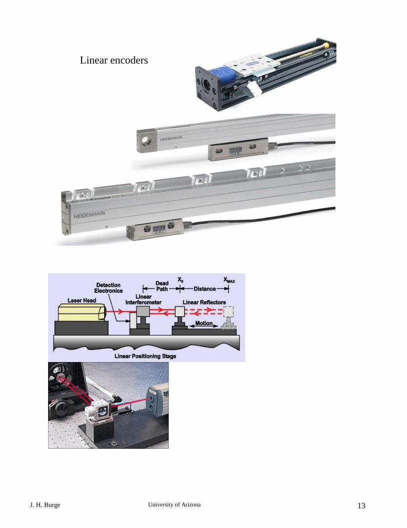