Motion Analysis of PLET during the Setting-Down Process
6
16 Journal of Architectural Environment & Structural Engineering Research | Volume 03 | Issue 04 | Special Issue | October 2020 Distributed under creative commons license 4.0 DOI: https://doi.org/10.30564/jaeser.v3i4.2542 Journal of Architectural Environment & Structural Engineering Research https://ojs.bilpublishing.com/index.php/jaeser ARTICLE Motion Analysis of PLET during the Setting-Down Process Hu Li 1* Mingxian Wang 2 1. ZhanJiang Nanhai West Oil Survey & Design Co.Ltd, Zhanjiang, Guangdong, 524000, China 2. CNOOC Ltd.Zhanjiang, Zhanjiang, Guangdong, 524000, China ARTICLE INFO ABSTRACT Article history Received: 9 November 2020 Accepted: 27 November2020 Published Online: 30 December 2020 The design analysis of Subsea PLET should consider various cases, in- cluding in-place analysis, lifting analysis, setting down analysis and so on. The size and vessel space should be checked in the structural design, and the fishing protection function should also be covered. The accurate set- ting-down process is the prerequisite for the successful construction of the subsea project. Therefore, it is necessary to simulate the various conditions included in the setting down process. Based on practical YC13-1 project and subsea environment condition, a special type of subsea PLET is de- signed for the pipe rehabilitation. Theoretical study is performed to discuss the load and Fluent software is used to simulate the problems encountered in the setting-down process. Comparison on the calculation results with ROV condition and without ROV condition, it indicates the effective sup- pression of the movement of PLET with ROV tractive action. The study can be a good reference and guidance for the design and construction of South China Sea oil and gas field project. Keywords: Subsea PLET Wave load FLUENT Setting-down process ROV traction *Corresponding Author: Hu Li, ZhanJiang Nanhai West Oil Survey & Design Co.Ltd, Zhanjiang, Guangdong, 524000, China; Email: [email protected] 1. Introduction U nderwater structures should have the advantages of strong serviceability, wide applicability, high reliability, low cost and so on, which can be used in deepwater oil and gas development projects. According to the installation methods, underwater structures can be divided into three types: installation with subsea pipeline, integral hoisting of the whole structure and underwater splicing by piece hoisting. According to service function, underwater structures can be divided into subsea pipeline terminal facilities (PLET), submarine pipeline terminal (PLEM) and Tee (ILTM), etc. The subsea PLET is a special underwater structure which connects the subsea pipeline, monitors and controls the operation state of the submarine pipeline and has the characteristics of complex operating environment and high installation accuracy. In order to ensure the safety of the corresponding pipeline construction and the safety of the PLET positioning on the seafloor, it is necessary to carry out the underwater dynamic analysis of the PLET during the installation pro- cess. In view of DP ship motion and the movement of PLET under current load, the force and motion of PLET is stud- ied, with consideration of whether ROV can complete the traction of PLET under construction and the collision force with flange interface, so as to instruct the actual construction [1] . In this paper, the load analysis and motion simulation of the subsea PLET used in YC13-1 subsea pipeline repair project are carried out, which provides technical support and guidance for subsequence construc- tion
Transcript of Motion Analysis of PLET during the Setting-Down Process
16
Journal of Architectural Environment & Structural Engineering Research | Volume 03 | Issue 04 | Special Issue | October 2020
Distributed under creative commons license 4.0 DOI: https://doi.org/10.30564/jaeser.v3i4.2542
Journal of Architectural Environment & Structural Engineering Research
https://ojs.bilpublishing.com/index.php/jaeser
ARTICLE
Motion Analysis of PLET during the Setting-Down Process
Hu Li1* Mingxian Wang2 1. ZhanJiang Nanhai West Oil Survey & Design Co.Ltd, Zhanjiang, Guangdong, 524000, China2. CNOOC Ltd.Zhanjiang, Zhanjiang, Guangdong, 524000, China
ARTICLE INFO ABSTRACT
Article historyReceived: 9 November 2020Accepted: 27 November2020Published Online: 30 December 2020
The design analysis of Subsea PLET should consider various cases, in-cluding in-place analysis, lifting analysis, setting down analysis and so on. The size and vessel space should be checked in the structural design, and the fishing protection function should also be covered. The accurate set-ting-down process is the prerequisite for the successful construction of the subsea project. Therefore, it is necessary to simulate the various conditions included in the setting down process. Based on practical YC13-1 project and subsea environment condition, a special type of subsea PLET is de-signed for the pipe rehabilitation. Theoretical study is performed to discuss the load and Fluent software is used to simulate the problems encountered in the setting-down process. Comparison on the calculation results with ROV condition and without ROV condition, it indicates the effective sup-pression of the movement of PLET with ROV tractive action. The study can be a good reference and guidance for the design and construction of South China Sea oil and gas field project.
Keywords:Subsea PLETWave loadFLUENTSetting-down processROV traction
*Corresponding Author:Hu Li,ZhanJiang Nanhai West Oil Survey & Design Co.Ltd, Zhanjiang, Guangdong, 524000, China;Email: [email protected]
1. Introduction
Underwater structures should have the advantages of strong serviceability, wide applicability, high reliability, low cost and so on, which can be used
in deepwater oil and gas development projects. According to the installation methods, underwater structures can be divided into three types: installation with subsea pipeline, integral hoisting of the whole structure and underwater splicing by piece hoisting. According to service function, underwater structures can be divided into subsea pipeline terminal facilities (PLET), submarine pipeline terminal (PLEM) and Tee (ILTM), etc. The subsea PLET is a special underwater structure which connects the subsea pipeline, monitors and controls the operation state of the submarine pipeline and has the characteristics of complex
operating environment and high installation accuracy. In order to ensure the safety of the corresponding pipeline construction and the safety of the PLET positioning on the seafloor, it is necessary to carry out the underwater dynamic analysis of the PLET during the installation pro-cess.
In view of DP ship motion and the movement of PLET under current load, the force and motion of PLET is stud-ied, with consideration of whether ROV can complete the traction of PLET under construction and the collision force with flange interface, so as to instruct the actual construction [1]. In this paper, the load analysis and motion simulation of the subsea PLET used in YC13-1 subsea pipeline repair project are carried out, which provides technical support and guidance for subsequence construc-tion

17
Journal of Architectural Environment & Structural Engineering Research | Volume 03 | Issue 04 | Special Issue | October 2020
Distributed under creative commons license 4.0 DOI: https://doi.org/10.30564/jaeser.v3i4.2542
2. Design of Subsea PLET
The subsea PLET mainly includes main frame, mudmat, skirt plate and corresponding accessory components, as shown in Figure 1. The following calculation should be included in the whole design work of PLET: in-place analysis, hoisting analysis, transportation analysis, stabil-ity analysis, trawl analysis, etc. According to the check of API RP 2A standard, the stress check UC of all members should be less than 1.0.
Figure 1. Structure diagram of subsea PLET
Figure 2. Photos of offshore installationNote: A: Overall structure of the PLET. The overall structure of the PLET is mainly composed of H-shaped steel, round pipe, steel plate, etc, and the material selection is defined according to corresponding national standards.B: Removable top cover. The top cover is removable for subsequent valve maintenance. The top cover of the PLET is set with graded guide rods in place. The guide rods are of variable diameter design. The sur-face of each guide rod and its sleeve or its adjacent structure is sprayed with white paint and numbered to facilitate the identification for divers and ROV.C: ROV operating mechanism. In order to operate the valve outside the protective cover and make ROV operate independently, a universal valve operating rod is designed. The operating rod is equipped with three-di-mensional position error compensation function through two universal joints and three-stage expansion structure to adjust the position error between the valve and the head cover.D: Eight-character guidance. Through the ROV thrust device, the ROV auxiliary positioning is realized, and the "eight character" guidance is designed to ride on the original submarine pipeline and put it in place ac-curately. The "eight character" guidance is not constrained vertically and can be retracted up and down. In addition, rubber blocks are pasted and
anchored on the inside of the eight-character guidance to avoid damag-ing the submarine pipeline when the protective cover is hoisted in place.E: The mudmat, limited by the derrick boom of ship hoisting, is designed as foldable type, and the spring pin is designed to pop up automatically. Therefore, when the folding dustproof plate is put down, it can be locked automatically to achieve the force transmission effect.
3. Calculation Theory and Load Definition
In addition to its self-weight, the marine environment load, including the influence of wind, wave and current[ 2,3], should be considered in the setting-down process of PLET at sea. When considering the simulation of PLET under the flow action, it is necessary to consider the ship motion under the flow load and the load on the PLET.
Refer to the calculation of flow load of subsea PLET, two methods can be adopted. For large-scale structures, computational fluid dynamics (CFD) method[ 4] can be used to calculate the flow load. For small-scale cylindrical structures, Morison formula can be adopted.
For small-scale cylindrical structure, the flow load can be divided into inertial force and tractive force:
F = + = ⋅ +F F C A U U C VI D D m2ρ ρ δUg g δt
(1)
where FI is the inertial force of the flow and FD is the tractive force.
According to standard, the values of tractive force coefficient and inertial force coefficient are as follows:
Smooth surface,CD=0.65 ,Cm=1.6 , and rough surface CD=1.05, Cm=1.2。
For large-scale structures, CFD method is adopted, which mainly uses the finite volume method to calculate the flow load, employs the discrete fluid domain and the discrete volume to replace the continuous space. Finite volume method uses the momentum conservation equa-tion in integral form of fluid motion. In practical simula-tion, the tractive force coefficient of the flow load can be obtained by the flow load per unit flow velocity, and the load under different flow velocity:
F C β ρAVc d=12
( )
2 (2)
where A is the projected area of the structure, Cd(β) is the tractive force coefficient respect to different flow an-gles β.
JONSWAP wave spectrum is used to simulate waves. Since JONSWAP spectrum is consistent with the observed wave statistics results in south China sea, JONSWAP spectrum is thus adopted to simulate the irregular waves:
18
Journal of Architectural Environment & Structural Engineering Research | Volume 03 | Issue 04 | Special Issue | October 2020
Distributed under creative commons license 4.0
S(ω exp β γ) = −αgω5
2
ωω
p4 exp
(ω ω/ 1
2σp
2
− )2
(3)
where α is the spectrum parameter, ωp is the spectrum peak frequency, γ is the spectrum peak parameter, and constant σ is determined by
when ω , 0.07< =ω σp ; when ω , 0.09> =ω σp , The wave spectrum parameters obtained from statistical
data are used to simulate the long peak irregular waves:
ζ 2 Δ sin= − +∈∑j 1
N
=
S ω ω ω k x( j j j j)
12 ( ) (4)
Ship motion consists of six degrees of freedom, includ-ing surge, sway, heave, and the roll, pitch and yaw rotated with x-axis. The ship motion equation under irregular wave action is
(m A η D η D f η Kη h t τ η τ dτ q t η η+ + + + + − =∞ )¨
1 2 ( ) ∫0
t
( ) ( ) ( , , )
(5)
where η = [x y z φ θ ψ]T , m is the mass ma-
trix, A∞ is the additional mass matrix at ω = ∞ , D1 is
the linear damping coefficient matrix, D f η2 ( ) is the
quadratic damping matrix, ∫0
t
h t τ η τ dτ( − ) ( ) is a hystere-
sis function, and q t η η( , , ) is the load. According to the actual working condition, finite ele-
ment analysis method is adopted to analyze the stress of the rigging. The rigging is in discrete elements, with upper boundary condition fixed and the bottom nodes moving along the PLET, so as to simulate the bearing capacity of the rigging. For the analysis on the motion of the rigging, the tractive force induced by the rigging and the flow load are applied on the PLET, namely the right term of the formula. Thus, the underwater motion of the PLET can be obtained by solving the kinematic equation.
4. Computational Models and Cases
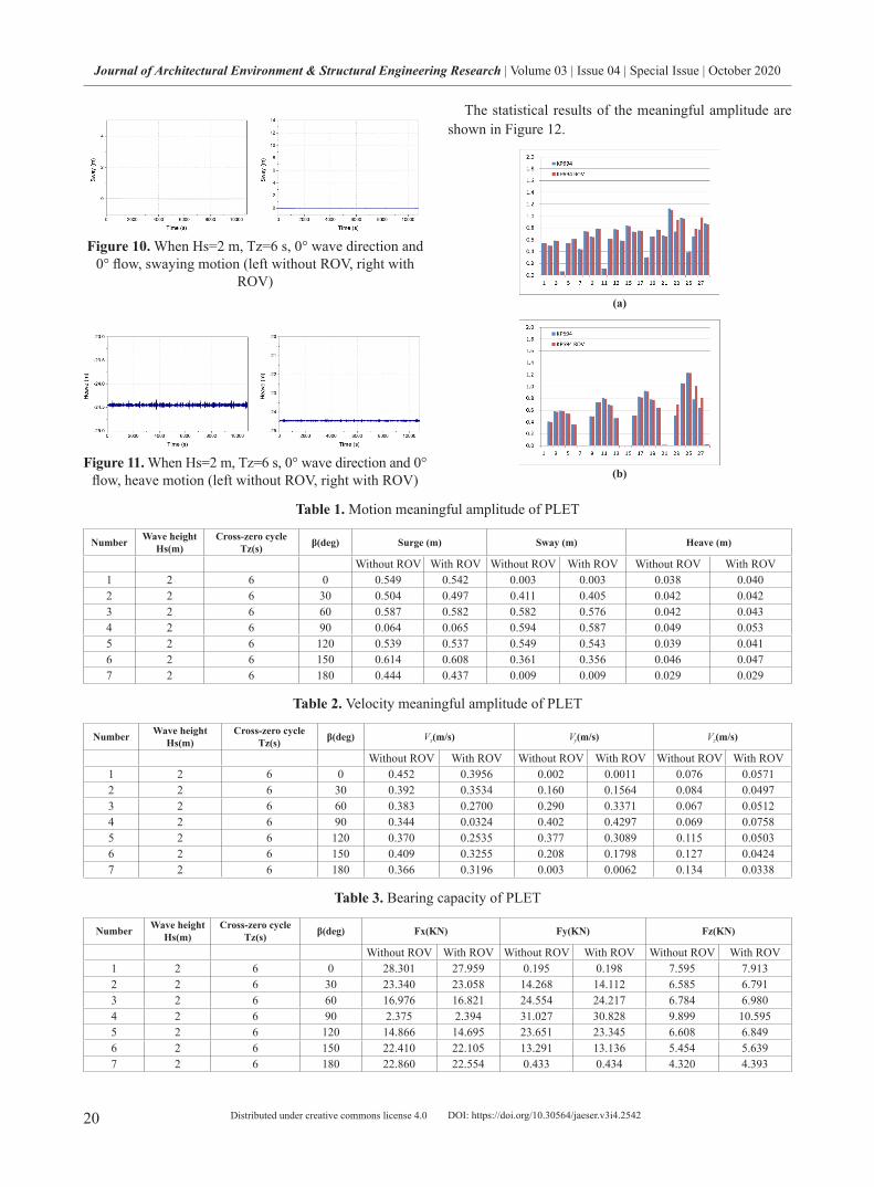
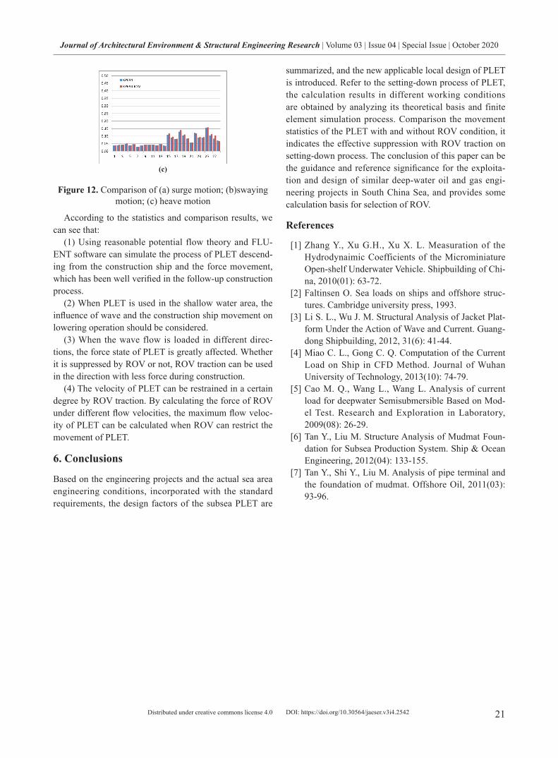
ICEM software is used to model the flow load of large-scale components on the PLET, and commercial com-putational fluid dynamics software FLUENT is used to calculate the flow load [5] The flow load of small-scale components is modelled by ANSYS.
The coordinates are cartesian right hand coordinates. The origin of the coordinate system is located on the base
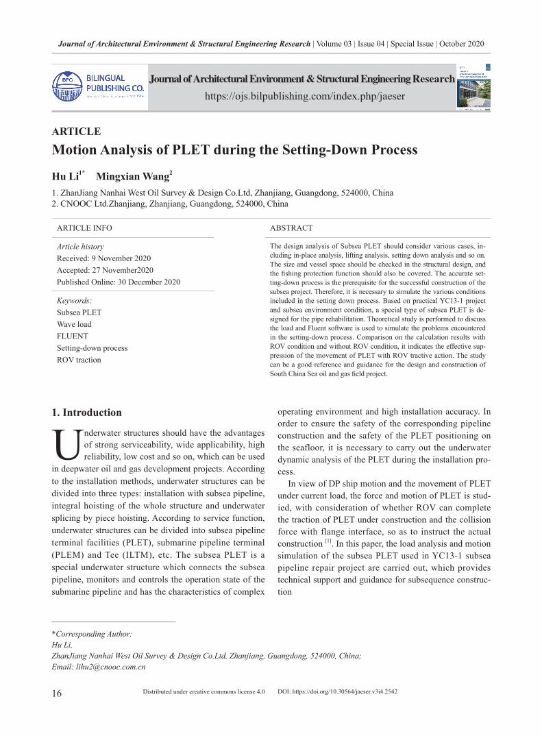
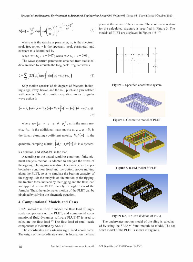
plane at the center of the structure. The coordinate system for the calculated structure is specified in Figure 3. The models of PLET are displayed in Figure 4-6 [6,7]
Figure 3. Specified coordinate system
Figure 4. Geometric model of PLET
Figure 5. ICEM model of PLET
Figure 6. CFD Unit division of PLET
The underwater motion model of the sling is calculat-ed by using the SESAM Simo module to model. The set down model of the PLET is shown in Figure 7.
DOI: https://doi.org/10.30564/jaeser.v3i4.2542

19
Journal of Architectural Environment & Structural Engineering Research | Volume 03 | Issue 04 | Special Issue | October 2020
Distributed under creative commons license 4.0
Figure 7. Schematic diagram of set down model of the PLET
For the calculation of setting-down flow load, the mo-tion of the PLET under different sea conditions is simulated with the once-a-year flow velocity environment, different flow velocity directions and different angles considered. In the Simo module of SESAM, setting-down model of the PLET is modeled and calculated to simulate the movement and acceleration of the PLET in the subsea, with the upper end of the rigging fixed and the flow load in the subsea con-sidered. The structural movement of the flow direction at 6 angles of 0°, 30°, 60°, 90°, 120°, 150° and 180° is simulat-ed, as shown in Figure 8. The bearing capacity of the PLET can be obtained by counting the meaningful values of the statistical movement and the acceleration.
(a) 0° flow direction
(b) 30° flow direction
(c) 90° flow direction
(d) 120° flow direction
(e) 150° flow direction
(f) 180° flow direction
(g) 210° flow direction
Figure 8. The structural movement of the PLET
In the case of a sudden change in flow velocity, 500KG (4.905KN) tractive force is applied on the PLET to sim-ulate ROV traction. The direction of the tractive force is opposite to that of the wave and flow. The motion of the PLET under the action of waves and sea flows is dis-cussed with the influence of ROV forces considered.
The bearing capacity of the PLET at a series of flow velocities is calculated based on the calculated fluid force and the collected ROV tractive force data and combined with the fluid force coefficient. According to the relation-ship between the force exerted on the PLET and the ROV tractive force, the maximum flow velocity that the PLET can withstand during installation is calculated.
5. Comparison of Calculated Results
28 working conditions with 7 wave current directions and 4 medium wave high periods considered are simulated in the setting-down process of PLET. The calculation results respect to 7 wave flow directions at one wave height peri-od are present in Figure 9-11.
Figure 9. When Hs=2 m, Tz=6 s, 0° wave direction and 0° flow, surge motion (left without ROV, right with ROV)
DOI: https://doi.org/10.30564/jaeser.v3i4.2542
20
Journal of Architectural Environment & Structural Engineering Research | Volume 03 | Issue 04 | Special Issue | October 2020
Distributed under creative commons license 4.0
Figure 10. When Hs=2 m, Tz=6 s, 0° wave direction and 0° flow, swaying motion (left without ROV, right with
ROV)
Figure 11. When Hs=2 m, Tz=6 s, 0° wave direction and 0° flow, heave motion (left without ROV, right with ROV)
The statistical results of the meaningful amplitude are shown in Figure 12.
(a)
(b)
Table 1. Motion meaningful amplitude of PLET
Number Wave height Hs(m)
Cross-zero cycleTz(s) β(deg) Surge (m) Sway (m) Heave (m)
Without ROV With ROV Without ROV With ROV Without ROV With ROV1 2 6 0 0.549 0.542 0.003 0.003 0.038 0.0402 2 6 30 0.504 0.497 0.411 0.405 0.042 0.0423 2 6 60 0.587 0.582 0.582 0.576 0.042 0.0434 2 6 90 0.064 0.065 0.594 0.587 0.049 0.0535 2 6 120 0.539 0.537 0.549 0.543 0.039 0.0416 2 6 150 0.614 0.608 0.361 0.356 0.046 0.0477 2 6 180 0.444 0.437 0.009 0.009 0.029 0.029
Table 2. Velocity meaningful amplitude of PLET
Number Wave height Hs(m)
Cross-zero cycleTz(s) β(deg) Vx(m/s) Vy(m/s) Vz(m/s)
Without ROV With ROV Without ROV With ROV Without ROV With ROV1 2 6 0 0.452 0.3956 0.002 0.0011 0.076 0.05712 2 6 30 0.392 0.3534 0.160 0.1564 0.084 0.04973 2 6 60 0.383 0.2700 0.290 0.3371 0.067 0.05124 2 6 90 0.344 0.0324 0.402 0.4297 0.069 0.07585 2 6 120 0.370 0.2535 0.377 0.3089 0.115 0.05036 2 6 150 0.409 0.3255 0.208 0.1798 0.127 0.04247 2 6 180 0.366 0.3196 0.003 0.0062 0.134 0.0338
Table 3. Bearing capacity of PLET
Number Wave height Hs(m)
Cross-zero cycleTz(s) β(deg) Fx(KN) Fy(KN) Fz(KN)
Without ROV With ROV Without ROV With ROV Without ROV With ROV1 2 6 0 28.301 27.959 0.195 0.198 7.595 7.9132 2 6 30 23.340 23.058 14.268 14.112 6.585 6.7913 2 6 60 16.976 16.821 24.554 24.217 6.784 6.9804 2 6 90 2.375 2.394 31.027 30.828 9.899 10.5955 2 6 120 14.866 14.695 23.651 23.345 6.608 6.8496 2 6 150 22.410 22.105 13.291 13.136 5.454 5.6397 2 6 180 22.860 22.554 0.433 0.434 4.320 4.393
DOI: https://doi.org/10.30564/jaeser.v3i4.2542
21
Journal of Architectural Environment & Structural Engineering Research | Volume 03 | Issue 04 | Special Issue | October 2020
Distributed under creative commons license 4.0
(c)
Figure 12. Comparison of (a) surge motion; (b)swaying motion; (c) heave motion
According to the statistics and comparison results, we can see that:
(1) Using reasonable potential flow theory and FLU-ENT software can simulate the process of PLET descend-ing from the construction ship and the force movement, which has been well verified in the follow-up construction process.
(2) When PLET is used in the shallow water area, the influence of wave and the construction ship movement on lowering operation should be considered.
(3) When the wave flow is loaded in different direc-tions, the force state of PLET is greatly affected. Whether it is suppressed by ROV or not, ROV traction can be used in the direction with less force during construction.
(4) The velocity of PLET can be restrained in a certain degree by ROV traction. By calculating the force of ROV under different flow velocities, the maximum flow veloc-ity of PLET can be calculated when ROV can restrict the movement of PLET.
6. Conclusions
Based on the engineering projects and the actual sea area engineering conditions, incorporated with the standard requirements, the design factors of the subsea PLET are
summarized, and the new applicable local design of PLET is introduced. Refer to the setting-down process of PLET, the calculation results in different working conditions are obtained by analyzing its theoretical basis and finite element simulation process. Comparison the movement statistics of the PLET with and without ROV condition, it indicates the effective suppression with ROV traction on setting-down process. The conclusion of this paper can be the guidance and reference significance for the exploita-tion and design of similar deep-water oil and gas engi-neering projects in South China Sea, and provides some calculation basis for selection of ROV.
References
[1] Zhang Y., Xu G.H., Xu X. L. Measuration of the Hydrodynaimic Coefficients of the Microminiature Open-shelf Underwater Vehicle. Shipbuilding of Chi-na, 2010(01): 63-72.
[2] Faltinsen O. Sea loads on ships and offshore struc-tures. Cambridge university press, 1993.
[3] Li S. L., Wu J. M. Structural Analysis of Jacket Plat-form Under the Action of Wave and Current. Guang-dong Shipbuilding, 2012, 31(6): 41-44.
[4] Miao C. L., Gong C. Q. Computation of the Current Load on Ship in CFD Method. Journal of Wuhan University of Technology, 2013(10): 74-79.
[5] Cao M. Q., Wang L., Wang L. Analysis of current load for deepwater Semisubmersible Based on Mod-el Test. Research and Exploration in Laboratory, 2009(08): 26-29.
[6] Tan Y., Liu M. Structure Analysis of Mudmat Foun-dation for Subsea Production System. Ship & Ocean Engineering, 2012(04): 133-155.
[7] Tan Y., Shi Y., Liu M. Analysis of pipe terminal and the foundation of mudmat. Offshore Oil, 2011(03): 93-96.
DOI: https://doi.org/10.30564/jaeser.v3i4.2542