
1 PUBLIC SPEAKING PUBLIC SPEAKING O PEN S OURCE M ANAGEMENT.

WISE MOS/GDS Interface Control Document
1
WISE MOS/GDS Interface Control Document
Version 1.0 Document Custodian: John Rakiewicz NATIONAL AERONAUTICS AND SPACE ADMINISTRATION JET PROPULSION LABORATORY California Institute of Technology Pasadena, California JPL D-34372
WISE MOS/GDS Interface Control Document
2
Prepared by: John Rakiewicz Approved by: Don Royer, MOS Manager
WISE MOS/GDS Interface Control Document
3
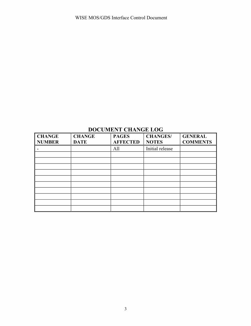
DOCUMENT CHANGE LOG CHANGE NUMBER
CHANGE DATE
PAGES AFFECTED
CHANGES/ NOTES
GENERAL COMMENTS
- All Initial release

WISE MOS/GDS Interface Control Document
4
1 PURPOSE The purpose of this document is to specify detailed descriptions of all the data interfaces between the different elements of the WISE Ground System (WGS). Section 4 describes the MOS/GDS architecture in terms of interface flows. Every MOS/GDS interface is depicted in Section 4. Section 5 provides a detailed description of each interface depicted in Section 4. Some interfaces will reference applicable multi-mission or Jason software interface specifications (SIS).
2 SCOPE The interfaces described in this document support all MOS/GDS activities related to conducting flight operations for the WISE mission. The major phases of the mission which are supported are listed below: (1) ATLO Support (2) Operational Readiness Testing and Operational Rehearsals (3) Launch and In Orbit Checkout Phase (4) Survey Phase
3 References and Applicable Documents
4 MOS/GDS System Interface ARCHITECTURE Section 4 partitions the GDS into a set of elements and then describes these elements in terms of interfaces. All interface names used in Section 4 are highlighted in BOLD. A detailed description of each interface is provided in Section 5.
4.1 WISE MOS/GDS Elements The WISE MOS/GDS elements are depicted in Figure 4.1.1. These elements and interfaces support WISE flight operations.
4.1.1 TDRSS Terminal at White Sands The TDRSS terminal at White Sands provides real time interfaces allowing the WISE MSA at JPL to receive both S-band and Ku-band telemetry data and to send uplink commands to the WISE spacecraft via an S-band uplink.
4.1.2 Survey Planning Center at UCLA The Survey Planning Team located at UCLA assesses the quality and progress of the ongoing survey of the infrared universe using the WISE infrared instrument with a set of tools developed for that purpose. This team generates periodic survey plans which are translated into uplink files and sent to the spacecraft for execution.

WISE MOS/GDS Interface Control Document
5
4.1.3 Science Data Processing and Archiving Center at IPAC The Science Data Processing Team develops the tools and performs the task of processing the high rate science data and archiving and distributing science data products. The team also generates an infrared image quality assurance report which is provided to the Survey Planning Team for accountability.
4.1.4 WISE Telemetry Command and Communications Subsystem (WTCCS)
The WTCCS is the core of the real time uplink and downlink system. It processes high rate science data utilizing a WISE high rate processor which is installed at White Sands and operated remotely from the WISE MSA at JPL. It processes low rate spacecraft engineering and instrument housekeeping data which is received over the S-band and Ku-band links.
4.1.5 WISE Test Bed at BATC The WISE test bed at BATC may be operated remotely from the MSA at JPL to support the testing of the WISE ground data system at JPL and to train operations personnel.
4.1.6 WISE Mission Support at BATC After Launch, the WISE MSA continues to routinely provide telemetry data and supporting information which may be utilized by on-call BATC engineering support personnel.
4.1.7 WISE Mission Support Area (MSA) at JPL The WISE MSA at JPL hosts the WISE GDS and the operations personnel who conduct flight operations for the WISE spacecraft.
4.1.8 TDRSS Scheduling Group The Sequence Team interacts with the TDRSS Scheduling Group via web based interface to schedule TDRSS contact support throughout the mission.
4.1.9 WISE Communications Network The WISE Communications Network utilizes both open and closed dedicated communications lines and the open internet for communications between the elements described in this document.

WISE MOS/GDS Interface Control Document
6
WISE/JPL GDSWhite Sands
IPAC
BATC
UCLA
Survey_Plan
TDRSS_Schedule
Rec_HK_Data
TLM_Frame_VC0,1,2
TDRSS_ODM
Sci_TLM_Packet_ID
TDRSS_GCMR
TDRSS_TC
WISE TLE
TDRSS_Schedule_Request
Mission_Data_Archive_File
Processed_Sci_Data
Process_Quick_Look_Sci
SOE
PEF
Spacecraft_Clock_File
CSVF
Memory_Load
Parameter_Update
SASF
SOE
PEF
OEF
Ephemeris_SPK
Ephemeris_SPK
Reconstructed_Pointing_CK
OEF/PEF/SOE
Spacecraft_Clock_File
CSVF
WISE_Image_Atlas
WISE_Source_Catalog
Science Community
Wise Test Bed/ATLO
TLM_Frame_VC0,1,2
TLM_Frame_VC10,12,38
CMD_Database
TLM_Database
Block_Database
Block_Database
STRATCOM
WISE TLE
FDF
State Vectors
IIRV ’s
UCLA
SDLTLM_Packet_ID
CK/SPK
S/C Clock File
Quality Assurance Report
Figure 4.1.1 MOS/GDS Elements and Interfaces
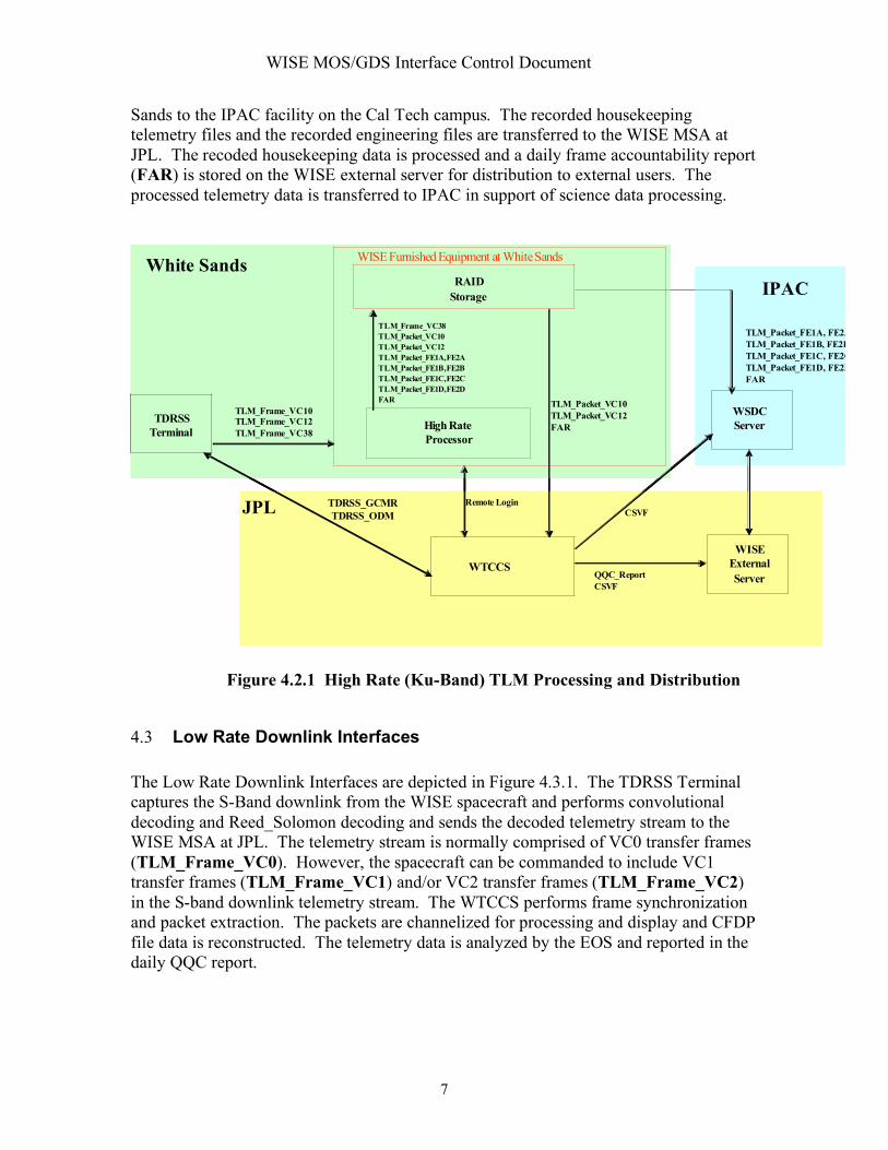
4.2 High Rate Downlink Interfaces The High Rate Downlink Interfaces are depicted in Figure 4.2.1. WISE high rate data is downlinked to the ground over the Ku-band transmitter with VC10 transfer frames (TLM_Frame_VC10) containing recorded engineering packets, VC12 transfer frames (TLM_Frame_VC12) containing CFDP processed file data and four streams of infrared instrument data (TLM_Frame_VC38). The transfer frames undergo convolutional decoding and are provided to the WISE high rate processor as a serial stream. The high rate processor performs Reed-Solomon decoding, frame synchronization, virtual channel splitting, and packet extraction. The extracted telemetry packets (TLM_Packet_APID) from each virtual channel are stored on the RAID device. All telemetry data transferred via VC12 transfer frames are in the form of CFDP processed telemetry data files. The telemetry data files are split into CFDP Protocol Data Units (PDU's) on the spacecraft. Each PDU is placed into an individual telemetry packet for transmission to the ground. File reconstruction from CFDP packets is performed by the WTCCS at JPL. Packet files (TLM_Packet_FE1A, FE1B, FE1C, FE1D, FE2A, FE2B, FE2C, FE2D) are generated from each of the four high rate science virtual channels. The packet files are stored on the RAID device at White Sands. The science packet files are transferred from White
WISE MOS/GDS Interface Control Document
7
Sands to the IPAC facility on the Cal Tech campus. The recorded housekeeping telemetry files and the recorded engineering files are transferred to the WISE MSA at JPL. The recoded housekeeping data is processed and a daily frame accountability report (FAR) is stored on the WISE external server for distribution to external users. The processed telemetry data is transferred to IPAC in support of science data processing.
TDRSS
TerminalHigh Rate
Processor
TLM_Frame_VC10
TLM_Frame_VC12
TLM_Frame_VC38
RAID
Storage
TLM_Frame_VC38
TLM_Packet_VC10
TLM_Packet_VC12
TLM_Packet_FE1A, FE2A
TLM_Packet_FE1B, FE2B
TLM_Packet_FE1C, FE2C
TLM_Packet_FE1D, FE2D
FAR
IPAC
WTCCS
JPL
White Sands
WSDC
Server
TDRSS_GCMR
TDRSS_ODM
WISE Furnished Equipment at White Sands
WISE
External
ServerQQC_Report
CSVF
TLM_Packet_FE1A, FE2A
TLM_Packet_FE1B, FE2B
TLM_Packet_FE1C, FE2C
TLM_Packet_FE1D, FE2D
FAR
TLM_Packet_VC10
TLM_Packet_VC12
FAR
Remote Login
CSVF
Figure 4.2.1 High Rate (Ku-Band) TLM Processing and Distribution
4.3 Low Rate Downlink Interfaces The Low Rate Downlink Interfaces are depicted in Figure 4.3.1. The TDRSS Terminal captures the S-Band downlink from the WISE spacecraft and performs convolutional decoding and Reed_Solomon decoding and sends the decoded telemetry stream to the WISE MSA at JPL. The telemetry stream is normally comprised of VC0 transfer frames (TLM_Frame_VC0). However, the spacecraft can be commanded to include VC1 transfer frames (TLM_Frame_VC1) and/or VC2 transfer frames (TLM_Frame_VC2) in the S-band downlink telemetry stream. The WTCCS performs frame synchronization and packet extraction. The packets are channelized for processing and display and CFDP file data is reconstructed. The telemetry data is analyzed by the EOS and reported in the daily QQC report.

WISE MOS/GDS Interface Control Document
8
TDRSS
Terminal
(WDISC/NCC)
White Sands
JPL
WTCCS
TDRSS_ODM
TDRSS_GCMR
WISE
S-Band
D/L
WISE
External
ServerQQC_Report
CSVF
TLM_Frame_VC0,1,2
TLM_Packet_VC0,1,2
QQC_Report
CSVF
BATC
Ball
Support
(OASIS & WTCCS Client)
TDRSS
Terminal
(WDISC/NCC)
White Sands
JPL
WTCCS
TDRSS_ODM
TDRSS_GCMR
WISE
S-Band
D/L
WISE
External
ServerQQC_Report
CSVF
TLM_Frame_VC0,1,2
TLM_Packet_VC0,1,2
QQC_Report
CSVF
BATC
Ball
Support
(OASIS & WTCCS Client)
Figure 4.3.1 Low Rate (S-Band) TLM Processing and Distribution
4.4 TDRSS Uplink Interfaces The TDRSS Uplink Process is depicted in Figure 4.4.1. The WTCCS in the WISE MSA at JPL establishes the state of the TDRSS ground station in preparation for commanding the WISE spacecraft by issuing remote control inputs (TDRSS_GCMR) to the station. The TDRSS ground station provides remote monitor data (TDRSS_ODM) specifying the state and status of the ground station. Upon establishing the proper configuration for commanding the spacecraft, command link transmission units (CLTU) are sent to the station uplink. The spacecraft uplink status is determined by processing VC0 telemetry transfer frames during the pass.

WISE MOS/GDS Interface Control Document
9
4.5 Sequence Integration and Command Generation Interfaces The Sequence Integration and Command Generation Process is depicted in Figures 4.5.1 and 4.5.2. The command generation process receives command inputs in two forms. They are files to be uplinked using the CCSDS File Delivery Protocol (CFDP) and discrete commands. There are three types of file loads for CFDP conversion and uplink. They are Parameter Update Files, Memory Load Files, and Sequence Command Load Files. File loads are input to a "CFDP Command Processor" which converts the file load into a set of Protocol Data Units (PDU) which are in the form of a PDU command mnemonic file (PDU_CMF). A log file is created for each file load converted into a PDU_CMF. The PDU_CMF is input to the Command Translator which generates a command packet (CMD_PKT) for each PDU. A PDU_CMF file will contain multiple PDU's. The Sequence Integration Process receives command inputs in the form of Spacecraft Activity Sequence Files (SASF) which undergo an integration process putting the commands to be sequenced in time order and performing constraint checking and state tracking on the integrated sequence. Initially, the integrated sequence is in the form of a command mnemonic file. The CMF is sent to the WTCCS for command translation and conversion into command packet files (CMD_PKT). The command packet files are then formatted into a sequence command load. The sequence command load is input to the

WISE MOS/GDS Interface Control Document
10
CFDP command processor. The CFDP processor also converts memory load files and parameter files. CFDP converted files are then input to the WTCCS command translator for conversion into uplink command packets Discrete commands are input to the Command Translator in the form of a Command Mnemonic File (CMF). A command packet is generated for each discrete command in the CMF. The CMF may contain multiple discrete commands. The command packets are input to the Command Processor which converts the them into VC0, VC1, or VC2 command link transmission units (CLTU). When the ground and spacecraft status is properly configured the CLTU's are sent to the TDRSS ground station for uplink. Uplink status is derived from the spacecraft telemetry data and remote monitor data from the station.
SASF’s
Block_Database
SC_Clock_File
OEF
TDRSS_Schedule
Sequence
Integration
(SEQGEN/SEG)PEF/SOE/SFOS
Command
Translator
&
Seq Load
Gen
(WTCCS)
CMF
CMD_Database
SC_Clock_File
Targeting
SASF
Target
Table
Generator
Simulator
(PGEN)
OEF
Wise SPK
TDRSS SPK’s
Survey_Plan
TDRSS_Schedule
SASF
Seq_CMD_LoadCFDP
Processor
(WTCCS)
Figure 4.5.1 Sequence Integration

WISE MOS/GDS Interface Control Document
11
CFDP
CMD
Processor
CMF (Discrete Cmd ’s)
Command
Translator
(WTCCS)
CMD_PKT
Command
Processor
(WTCCS)CLTU
(Uplink_Status from TM)
(VC0,VC1,VC2)
CMD_Database
SEQ_CMD_Load
Memory_Load
Parameter_LoadWhite Sands
CFDP
CMD
Processor
CMF (Discrete Cmd ’s)
Command
Translator
(WTCCS)
CMD_PKT
Command
Processor
(WTCCS)CLTU
(Uplink_Status from TM)
(VC0,VC1,VC2)
CMD_Database
SEQ_CMD_Load
Memory_Load
Parameter_LoadWhite Sands
Figure 4.5.2 Command Generation
4.6 Navigation System Interfaces The Navigation Process is depicted in Figure 4.6.1. A two line element (TLE) is provided for the WISE spacecraft by the Flight Dynamics Facility at GSFC during the launch and early operations phase (LEOP) and by NORAD during the prime science phase (PSP). The WISE TLE and TDRSS TLE's are processed to produce an Orbit Events File (OEF). TDRSS support is requested via internet access using the Space Network Access System (SNAS) The WISE TLE is sent to the White Sands Operations Center. The Navigation Process includes the generation of the spacecraft ephemeris in the form of an SP-kernel (Ephemeris_SPK), and the reconstructed attitude of the spacecraft in the form of a C-Kernel (Reconstructed_Pointing_CK).

WISE MOS/GDS Interface Control Document
12
Figure 4.6.1 Navigation Process
4.7 Science Planning and Data Processing Interfaces
The survey planning task is performed by the WISE Survey Planning Team at the University of California at Los Angeles (UCLA). Figure 4.7.1 depicts the interfaces supporting the survey planning task. The science data processing task is performed by the WISE Science Data Processing Team located at the Infrared Processing and Analysis Center (IPAC). Figure 4.7.2 depicts the interfaces supporting the science data processing task.

WISE MOS/GDS Interface Control Document
13
WISE
External
Server
Server
Survey Plan
Inputs
WISE
MOS/GDS
UCLA
JPL
Survey Plan Inputs
SOE/SFOS
WISE_SPK
OEF
SOE
WISE_SPK
OEF
IPAC
WSDCSci QA Report
WISE
External
Server
Server
Survey Plan
Inputs
WISE
MOS/GDS
UCLA
JPL
Survey Plan Inputs
SOE/SFOS
WISE_SPK
OEF
SOE
WISE_SPK
OEF
IPAC
WSDCSci QA Report
Figure 4.7.1 Survey Planning
IPACWhite Sands
JPL
WISE
High Rate Processor
Data
Processing
And
Archive
Facilities
Science TLM Packets
FAR
HRP File Summary
WTCCS
ServerWISE SP Kernel
WISE C Kernel
WISE SCLK Kernel
OEF/SOE
TLM_CSVF
WISE_Image_Atlas
WISE_Source_Catalog
Mission_Data_Archive_File
Processed_Sci_Data
Process_Quick_Look_Sci
Sci_QA_Report

WISE MOS/GDS Interface Control Document
14
Figure 4.7.2 Science Data Processing
4.8 BATC Support Interfaces Interfaces between the WISE MSA at JPL and WISE Support Facilities at BATC are established during the ATLO phase. In preparation for conducting Flight Operations from the WISE MSA at JPL, the interfaces between JPL and BATC undergo a reconfiguration. Figure 4.9.1 depicts the interface configuration between JPL and BATC during the ATLO campaign and in support of flight operations.
WTCCS
TLM_Frame_VC0,1,2
TLM_Packet_VC10,12
FARWhite
Sands
BATC
WISE
External
Server
TLM_Packet_VC0,1,2,10,12
QQC_Report
CSVF
Ball SupportTLM_database
CMD_database
SOE/SFOS
PEF
Spacecraft_Clock_File
Memory_Load
Parameter_Update
SASF
ATLO
Wise Test Bed
TLM_Frame_VC0,1,2
TLM_Packet_VC10,12
TLM_Packet_FE1A, FE2A
TLM_Packet_FE1B, FE2B
TLM_Packet_FE1C, FE2C
TLM_Packet_FE1D, FE2D
Spacecraft_Clock_File
WTB Inputs
(OASIS & WTCCS Client)
SEQSOE/SFOS
PEF
Figure 4.9.1 JPL/BATC Interfaces

WISE MOS/GDS Interface Control Document
15
4.9 MOS/GDS Interface List
GENERIC INTERFACE NAME DESCRIPTION PROVIDER CUSTOMER
Alarm Report Alarm_Report
A listing of RED telemetry alarms incurred during a downlink session
WTCCS EOS
Block Dictionary Database Block_Database
Description of each spacecraft and ground expandable block
SEQ SEQ
CFDP Packets for Downlink CFDP_PDU_Downlink
Downlink Protocol Data Units (PDU’s) containing either downlink metadata, end of file indication, or telemetry file data
S/C WTCCS
CFDP Uplink Protocol Data Unit CFDP_Uplink_PDU
CFDP PDU’s containing either uplink metadata, end of file indication, or command data
WTCCS S/C
Command Data Base File CMD_Database
Data base containing the detailed characteristics of each spacecraft command mnemonic
BATC WTCCS SEQ
Command Packet File CMD_Packet
ASCII file containing command packets to be processed into CLTU's for uplink
WTCCS WTCCS
Command Mnemonic File CMF
File containing mnemonics and directives to the command data base to translate command mnemonics into command packets
SEQ WTCCS EOS
WTCCS
Housekeeping Data Archive File HK_Data_Archive_File
Housekeeping data file (compressed) for long term deep archive
WSDC All

WISE MOS/GDS Interface Control Document
16
GENERIC INTERFACE NAME DESCRIPTION PROVIDER CUSTOMER
HRP Frame Accountability Report HRP_FAR
The FAR reports frame accountability and statistics for each virtual channel (VC10, VC12, VC38). This report is used for retransmitting lost frames.
HRP WTCCS
HRP File Summary Report HRP_File_Summary
A listing of files produced by the HRP during a single TDRSS contact pass
EOS WSDC
HRP Status Packet HRP_Status_Pkt
A periodic packet generated by the HRP providing the status of the HRP
HRP WTCCS
Improved Inter-Range Vector IIRV
The IIRV is derived from a TLE and provided to WOTIS for TDRSS pointing
EOS WOTIS
Memory Load File Memory_File_Load
Binary Memory Load file input to the CFDP command processor
EOS WTCCS
Mission Data Archive File Mission_Data_Archive_File
Mission data file (compressed) for long term deep archive
EOS WSDC
Orbiter Events File OEF
Text file containing key spacecraft and ground events including the TDRSS pass schedule
NAV EOS, SEQ
Parameter Update File Parameter_File_Load
Binary Parameter File input to the CFDP command processor
SEQ WTCCS
Spacecraft Predicted Events File PEF
SEQGEN output file predicting spacecraft events resulting from the nominal execution of an on-board stored sequence
SEQ All
Processed Quick Look Science Report Processed_Quick_Look_Rpt
Initial report assessing science data quality
WSDC All
Processed Science Data Processed_Sci_Data
Routinely processed science data
WSDC All

WISE MOS/GDS Interface Control Document
17
GENERIC INTERFACE NAME DESCRIPTION PROVIDER CUSTOMER
Recorded Housekeeping Data Rec_HK_Data
File containing recorded housekeeping telemetry in packet format
HRP WTCCS
Spacecraft Activity Sequence File SASF
SEQGEN input request file containing timed commands for integration into an on-board stored sequence
All SEQ
Science Data Archive File Sci_Data_Archive_File
Science data file (compressed) for long term deep archive
WSDC All
Science Telemetry Packet Files Science_TLM_Packet_ID
Science Telemetry Packet files segregated by APID
WTCCS/HRP
WSDC
Sequence of Events File SOE
Time ordered listing of scheduled spacecraft and ground events
SEQ All
Spacecraft Clock File Spacecraft_Clock_File
Listing of correlated spacecraft clock and UTC data points
EOS All
Spacecraft Sequence File SSF
SEQGEN output file providing a time ordered listing of all sequenced commands
SEQ All
Sequence of Events File SOE
Time ordered listing of scheduled spacecraft
SEQ All
Survey Plan Survey_Plan
Survey Plan for input to PGEN
EOS EOS
Survey Plan Input Survey_Plan_Input
Inputs to the Survey Planning Software
SPS EOS
TDRSS Remote Control TDRSS_GCMR
Socket interface for sending TDRSS remote control directives
WTCCS TDRSS
TDRSS Remote Monitor Data Stream TDRSS_ODM
Data stream via socket connection of TDRSS remote monitor status information
TDRSS WTCCS
TDRSS Pass List TDRSS_Pass_List
A list of TDRSS passes SEQ EOS, NAV

WISE MOS/GDS Interface Control Document
18
GENERIC INTERFACE NAME DESCRIPTION PROVIDER CUSTOMER
TDRSS Tele-command Path TDRSS_TC
Socket interface for sending command data in the form of CLTU’s to White Sands for uplink to the S/C.
WTCCS TDRSS
TDRSS Telemetry Stream TDRSS_TLM
TDRSS telemetry stream either from WDISK or the Ku-band interface to the HRP
WSC WTCCS/HRP
Two Line Element File TLE
WISE and TDRSS TLE's define their orbital position and rate as a function of time
NORAD, FDF
NAV, SPS
Telemetry Comma Separated Value Files TLM_CSVF
Comma Separated Value Files containing selected engineering data channels
WTCCS All
Telemetry Data Base File TLM_Database
Data base containing the detailed characteristics of each spacecraft telemetry parameter
BATC WTCCS
Telemetry Frame Stream TLM_Frame_VCID
Raw convolutional decoded CADU telemetry transfer frames for virtual channels 0, 1, 2, 10, 12, 38
TDRSS ATLO Testbed
WTCCS/HRP
Engineering Telemetry Extracted Packet Files TLM_Packet_ID
Engineering and CFDP Packet files segregated by packet type
WTCCS/HRDP
EOS
WISE C Kernel WISE_C_Kernel
Reconstructed or predicted spacecraft orientation in NAIF/SPICE CK format
NAV All
WISE Spacecraft Clock Kernel WISE_SCLK_Kernel
Listing of correlated spacecraft clock and UTC data points in the NAIF/SPICE SCLK format
EOS All
WISE SP Kernel WISE_SP_Kernel
WISE and TDRSS vector files in the NAIF/SPICE SPK format
NAV All
WISE State Vector WISE_State_Vector
WISE ephemeris provided by FDF at GSFC
FDF NAV

WISE MOS/GDS Interface Control Document
19
GENERIC INTERFACE NAME DESCRIPTION PROVIDER CUSTOMER
WISE MOS/GDS Interface Control Document
20
5 MOS/GDS System Interface Detailed Descriptions

WISE MOS/GDS Interface Control Document
21
INTERFACE DESCRIPTION FORM Interface name: Alarm_Report Alarm Report - A listing of RED telemetry alarms incurred during a downlink session EXCHANGE DESCRIPTION
Provider: WTCCS Consumer: EOS
Server: WISE Server Client: EOS
Protocol: FTP Connection initiator: EOS
Schedule: As needed
Comment: File Naming Convention: WIS_WTCCS_Alarm_Report_YYYY_DDD_HH_MM_SS.txt
INTERFACE DATA DESCRIPTION The alarm log file is generated upon detection of a telemetry parameter which violates a specified alarm value. An example of the Telemetry Alarm Log file is shown in below. The fields displayed are:
TimeStamp—packet time when the alarm occurred Color—alarm state (RL, YL, YH, RH, GR) Mnemo—mnemonic of parameter in alarm Value—value of parameter in alarm RL—Red Low limit YL—Yellow Low limit YH—Yellow Hi limit RH—Red High limit
TimeStamp Color Mnemo Value RL YL YH RH 2007-123T04:59:59 YH Battemp 89 10 20 80 90 2007-123T05:01:01 RH Battcur 57 10 20 30 40

WISE MOS/GDS Interface Control Document
22

WISE MOS/GDS Interface Control Document
23
INTERFACE DESCRIPTION FORM Interface name: Block_Database Block Database - Description of each spacecraft and ground expandable block EXCHANGE DESCRIPTION
Provider: EOS Consumer: SEQ
Server: WISE Server Client: SEQGEN
Protocol: FTP Connection initiator: SEQ
Schedule: As needed
Comment: The block database is configuration controlled. File Naming Convention: WIS_SEQ_Block_Database_YYYY_DDD_HH_MM_SS.txt
INTERFACE DATA DESCRIPTION See the following document for interface details: Wide-field Infrared Survey Explorer (WISE) Block Dictionary Release Version 1.0, May 30, 2007 JPL D-38489

WISE MOS/GDS Interface Control Document
24
INTERFACE DESCRIPTION FORM Interface name: CFDP_PDU_Downlink
Protocol Data Units (PDU’s) containing downlink metadata, end of file indication, or telemetry file data
EXCHANGE DESCRIPTION
Provider: WTCCS Consumer: WTCCS
Server: WTCCS Client: WTCCS
Protocol: Connection initiator:
Schedule:
Comment: INTERFACE DATA DESCRIPTION
WISE MOS/GDS Interface Control Document
25
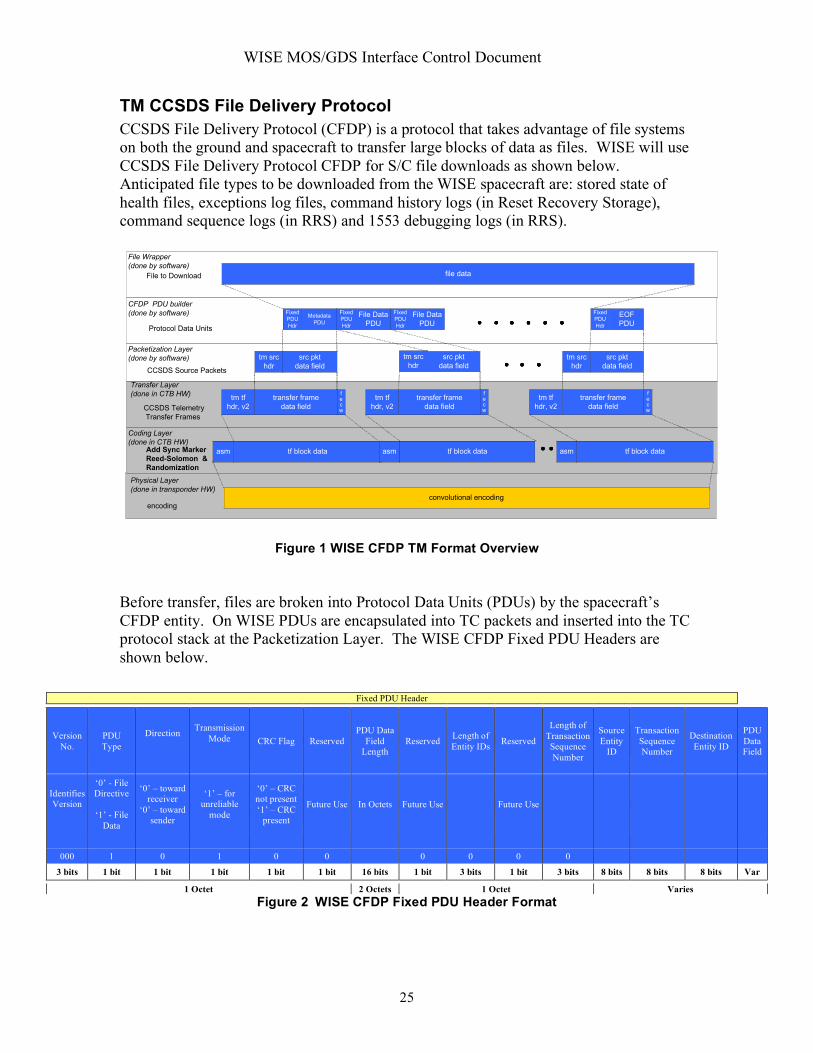
TM CCSDS File Delivery Protocol CCSDS File Delivery Protocol (CFDP) is a protocol that takes advantage of file systems on both the ground and spacecraft to transfer large blocks of data as files. WISE will use CCSDS File Delivery Protocol CFDP for S/C file downloads as shown below. Anticipated file types to be downloaded from the WISE spacecraft are: stored state of health files, exceptions log files, command history logs (in Reset Recovery Storage), command sequence logs (in RRS) and 1553 debugging logs (in RRS).
File Wrapper
(done by software)
File to Download file data
CFDP PDU builder
(done by software)
Protocol Data Units
tm src
hdr
src pkt
data field
src pkt
data field
tm tf
hdr, v2
transfer frame
data field
tm tf
hdr, v2
transfer frame
data field
tm tf
hdr, v2
transfer frame
data field
tm src
hdr
src pkt
data field
tm src
hdrCCSDS Source Packets
CCSDS Telemetry
Transfer Frames
asm tf block dataAdd Sync Marker
Reed-Solomon &
Randomization
Packetization Layer
(done by software)
Coding Layer
(done in CTB HW)
Transfer Layer
(done in CTB HW) fecw
fecw
fecw
Metadata
PDU
EOF
PDU
File Data
PDU
asm tf block data
convolutional encoding
Physical Layer
(done in transponder HW)
asm tf block data
File Data
PDU
encoding
Fixed
PDU
Hdr
Fixed
PDU
Hdr
Fixed
PDU
Hdr
Fixed
PDU
Hdr
Figure 1 WISE CFDP TM Format Overview
Before transfer, files are broken into Protocol Data Units (PDUs) by the spacecraft’s CFDP entity. On WISE PDUs are encapsulated into TC packets and inserted into the TC protocol stack at the Packetization Layer. The WISE CFDP Fixed PDU Headers are shown below.
Fixed PDU Header
Version No.
PDU Type
Direction Transmission Mode CRC Flag Reserved
PDU Data Field
Length Reserved Length of
Entity IDs Reserved
Length of Transaction Sequence Number
Source Entity
ID
Transaction Sequence Number
Destination Entity ID
PDU Data Field
Identifies Version
‘0’ - File Directive
‘1’ - File
Data
‘0’ – toward receiver
‘0’ – toward sender
‘1’ – for unreliable
mode
‘0’ – CRC not present ‘1’ – CRC
present
Future Use In Octets Future Use Future Use
000 1 0 1 0 0 0 0 0 0
3 bits 1 bit 1 bit 1 bit 1 bit 1 bit 16 bits 1 bit 3 bits 1 bit 3 bits 8 bits 8 bits 8 bits Var 1 Octet 2 Octets 1 Octet Varies
Figure 2 WISE CFDP Fixed PDU Header Format

WISE MOS/GDS Interface Control Document
26
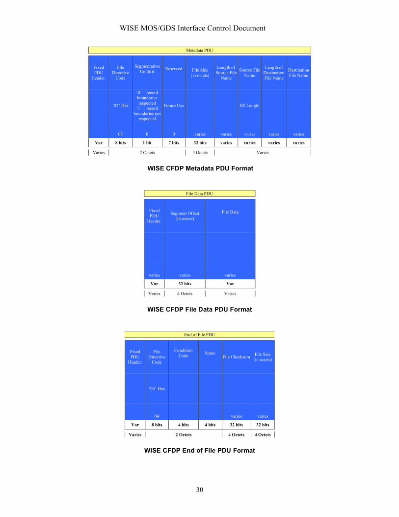
CFDP may be used in unreliable mode or one of four reliable modes: immediate, deferred, prompted, or asynchronous. In unreliable mode, the communication is only one way, and no attempt is made by the receiving entity to communicate with the sender about file completeness. WISE will use CFDP in unreliable mode only. Therefore the Transmission mode value in the Fixed PDU Header will always be ‘1’, unacknowledged. The CRC flag in the Fixed PDU Header is not used on WISE. FSW has limited the Transaction Sequence Length and Entity ID Lengths to 8 bits (one octet). Though the CFDP standard allows the transmission of multiple files simultaneously, WISE plans to operate with the restriction that files will be transferred in series. This is being done to minimize the amount of memory space that is set aside for storing outgoing file pointer information on the spacecraft. The WISE Metadata PDU, File Data PDU and EOF PDU definitions are shown in Figure 3 below..
Metadata PDU
Fixed PDU
Header.
File Directive
Code
Segmentation Control Reserved File Size
(in octets)
Length of Source File
Name
Source File Name
Length of Destination File Name
Destination File Name
‘07’ Hex
‘0’ – record boundaries respected
‘1’ – record boundaries not
respected
Future Use 8X Length
07 0 0 varies varies varies varies varies
56 bits 8 bits 1 bit 7 bits 32 bits varies varies varies varies
7 octets 2 Octets 4 Octets Varies
Figure 3 WISE CFDP Metadata PDU Format
File Data PDU
Fixed PDU
Header.
Segment Offset (in octets)
File Data
varies varies varies
56 bits 32 bits Var
7 octets 4 Octets Varies Figure 4 WISE CFDP File Data PDU Format

WISE MOS/GDS Interface Control Document
27
End of File PDU
Fixed PDU
Header.
File Directive
Code
Condition Code Spare
File Checksum File Size (in octets)
‘04’ Hex
04 varies varies
56 bits 8 bits 4 bits 4 bits 32 bits 32 bits
7 octets 2 Octets 4 Octets 4 Octets Figure 5 WISE CFDP End of File PDU Format
There will be one packet type (Appid/PacketID) for all CFDP PDUs. Packet lengths will vary with PDU length. The maximum software generated telemetry PDU size for the WISE spacecraft will be 994 bytes to maximize OE heritage. The PDU is sized to fit (with its 14 byte packet header) within the data field of a TM Transfer Frame. The maximum length of a PDU-data carrying space will be 1107 bytes (this does not include the M_PDU header). The PDU’s will be encapsulated into telemetry packets and downlinked via VC2 or VC12 transfer frames.

WISE MOS/GDS Interface Control Document
28
INTERFACE DESCRIPTION FORM Interface name: CFDP_Uplink_PDU Uplink Protocol Data Units that contain uplink metadata, end of file indication, or command data EXCHANGE DESCRIPTION
Provider: WTCCS Consumer: WTCCS
Server: WTCCS Client: WTCCS
Protocol: Connection initiator:
Schedule:
Comment: This is a intermediate command product which continues on for packetization and CLTU generation. See the CMD_Packet interface description for packetization.
INTERFACE DATA DESCRIPTION WISE plans to use the unreliable mode of CFDP, wherein the entire File Delivery Unit (FDU) is sent up to the spacecraft, then the spacecraft issues a file verification message in telemetry or a protocol error is declared. File Wrapper
(done by software)
File to Upload file data
CFDP PDU builder
(done by software)
Protocol Data Units
tc src
header
cmd source
data
tc tf
hdr
transfer frame
data field
tc tf
hdr
transfer frame
data field
tc src
hdr
cmd source
dataTC source packets
TC transfer frames
start
sequence
code block
data
code block
data
tail
sequenceCLTUs
b
c
h
b
c
h
code block
data
b
c
h
Packetization Layer
(done by software)
Coding Layer
(done by CTB HW)
Transfer Layer
(done by CTB HW) fecw
fecw
tail
sequence
code block
data
b
c
h
code block
data
b
c
h
start
sequence
code block
data
b
c
h
tc src
hdr
cmd source
data
tc tf
hdr
transfer frame
data field
fecw
tc tf
hdr
tf data
field
hdrcmd
data
fecw
Metadata
PDU
File Data
PDU
Fixed
PDU
Hdr
Fixed
PDU
Hdr
File Data
PDU
Fixed
PDU
Hdr
EOF
PDU
Fixed
PDU
Hdr
WISE CFDP TC Overview The fixed PDU TC header is shown below:
WISE CFDP TC Overview

WISE MOS/GDS Interface Control Document
29
Fixed PDU Header
Version No.
PDU Type
Direction Transmission Mode CRC Flag Reserved
PDU Data Field
Length Reserved Length of
Entity IDs Reserved
Length of Transaction Sequence Number
Source Entity
ID
Transaction Sequence Number
Destination Entity ID
PDU Data Field
Identifies Version
‘0’ - File Directive
‘1’ - File
Data
‘0’ – toward receiver
‘1’ – toward sender
‘1’ – for unreliable
mode
‘0’ – CRC not present ‘1’ – CRC
present
Future Use In Octets Future Use Future Use
000 1 0 1 0 0 0 0 0 0
3 bits 1 bit 1 bit 1 bit 1 bit 1 bit 16 bits 1 bit 3 bits 1 bit 3 bits Var Var Var Var 1 Octet 2 Octets 1 Octet Varies
Though the CFDP standard allows the transmission of multiple files simultaneously, WISE plans to operate with the restriction that files will be transferred in series. This is being done to minimize the amount of memory space that is set aside for receipt of files on the spacecraft. A file that is received will first be written into a temporary location. Upon reception of the complete file, the file will be relocated to its final destination. The reason for using a temporary file is to avoid the situation where a file is being overwritten from the ground when a communication error aborts the transaction, leaving the file partially overwritten and unusable. The current plan for WISE is that a file uplink session monopolizes the uplink channel. In other words, there will not be any Software Commands or Level Zero Commands transmitted during a file transmission. This is acceptable due to the pre-planned nature of file uplinks to the spacecraft. There is no anticipated need to send immediate commands on an impromptu basis, but should an emergency arise, the file uplink can be cancelled to open the channel for Level Zero or Software Commands. There will be one packet type (AppID/PacketID) defined for all CFDP PDUs. Packet lengths will vary with PDU length. The software shall limit CFDP Protocol Data Unit telecommand source packets to a maximum data field size of 994 bytes or less, limiting the maximum Telecommand Transfer Frames PDU size to 1008 bytes. The WISE Metadata PDU, File Data PDU and EOF PDU definitions are shown in the Figures below.
WISE MOS/GDS Interface Control Document
30
Metadata PDU
Fixed PDU
Header.
File Directive
Code
Segmentation Control Reserved File Size
(in octets)
Length of Source File
Name
Source File Name
Length of Destination File Name
Destination File Name
‘07’ Hex
‘0’ – record boundaries respected
‘1’ – record boundaries not
respected
Future Use 8X Length
07 0 0 varies varies varies varies varies
Var 8 bits 1 bit 7 bits 32 bits varies varies varies varies
Varies 2 Octets 4 Octets Varies
WISE CFDP Metadata PDU Format
File Data PDU
Fixed PDU
Header.
Segment Offset (in octets)
File Data
varies varies varies
Var 32 bits Var
Varies 4 Octets Varies
WISE CFDP File Data PDU Format
End of File PDU
Fixed PDU
Header.
File Directive
Code
Condition Code Spare
File Checksum File Size (in octets)
‘04’ Hex
04 varies varies
Var 8 bits 4 bits 4 bits 32 bits 32 bits
Varies 2 Octets 4 Octets 4 Octets
WISE CFDP End of File PDU Format

WISE MOS/GDS Interface Control Document
31
WISE CFDP TC Overview

WISE MOS/GDS Interface Control Document
32
INTERFACE DESCRIPTION FORM Interface name: CMD_Database Command Data Base File - Data base containing the detailed characteristics of each spacecraft command mnemonic EXCHANGE DESCRIPTION
Provider: BATC Consumer: WTCCS
Server: WISE External Server Client: WTCCS
Protocol: FTP Connection initiator: WTCCS
Schedule: Whenever updated and provided by BATC
Comment: File naming convention: WIS_BATC_CMD_Database_YYYY_DDD_HH_MM_SS.txt
INTERFACE DATA DESCRIPTION The Command Database provided by BATC is an EXCEL file which is converted to the WISE CommandDatabase format used by the WTCCS. The Command workbook includes:
• General Command Info (mnemonic, description, etc.); worksheet name: [ cmd ] • Command Parameters (subfields); worksheet name: [ cmd_param ] • Command Parameter State Conversions; worksheet name: [
cmd_param_conv_state ] • Command - Telemetry Responses; worksheet name: [ cmd_tlm_response ]
The layout of the EXCEL spreadsheets is described below:
Command Workbook Worksheet [cmd]: General Command Info
• spacecraft [required] o 1-10 character string abbreviation used to indicate the spacecraft this
command is associated with; abbr must match db spacecraft definition record abbr. value
WISE uses WISE [WS] • external_element
o An OASIS concept, this 1-16 char string allows groups of command and telemetry data to be divided up internally to OASIS, following somewhat arbitrary criteria
WISE MOS/GDS Interface Control Document
33
o Value is required only for payload/instrument, otherwise value is preset by App ID association
o WISE use limited to 2 chars [TBR] • app_id [required]
o The application ID or reserved number (value must be unique per spacecraft)
o Integer values 1 – 255 WISE reserves 255 for the CTB WISE reserves 254 for the MUB [TBR]
• pkt_id [required] o The packet ID (value must be unique per application) o Integer values 1 – 255; blocks are reserved for monitor and monitor agent
packets • pkt_name
o [optional] The name of the packet; informational only o String; 1-80 char. max
• mnemonic [required] o The unique 1-12 char ground system identifier for this command (note: 12
is an OASIS limitation) o alpha-numeric and underscore chars are allowed, no spaces o naming conventions are program specific; DI uses an additional 3 char
prefix to specify the OASIS ext_element within the mnemonic bringing the allowed character total to 15; this type of mnemonic is spit into its parts during exports for OASIS
• new_mnemonic o This is used when changing an existing mnemonic (useful for a
before/after mnemonic log) o Any values entered here must follow the same rules as for the mnemonic
field • cmd_type [required]
o String indicating the type of command o Supported values are SWC (software command), HWC (hardware
command) • export_to_ground
o TRUE/FALSE: set to TRUE if the ground system needs to be able to send this particular command (sometimes templates are defined); automatically set to FALSE if mnemonic = 1-NOT_USED
o Default = TRUE • init_only
o TRUE/FALSE: set to TRUE if this command is only valid during initialization
o Default = FALSE • test_only
o TRUE/FALSE: set to TRUE if this command is only valid during test o Default = FALSE
• critical

WISE MOS/GDS Interface Control Document
34
o TRUE/FALSE: set to TRUE if this is a command that is critical (definition of “critical” and the requirements for two-step or interlocked command are program-specific [TBR for WISE])
o Default = FALSE • hazardous
o TRUE/FALSE: set to TRUE if this is a command that could cause damage to spacecraft or personnel
o Default = FALSE • delay
o [optional] Short text field describing any delay (value and units) required after command is executed (before next command)
• required_predecessor_mnemonic o [optional] If the command must always follow another command, enter
that command's mnemonic here • required_predecessor_description [required]
o [optional] one line short description describing the command predecessor (<80 chars)
• required_predecessor_notes o [optional] larger free-form text field used to capture any notes about this
command predecessor (<3000 chars) • required_predecessor_hyperlink
o [optional] text field used to store the URL of an online document that would be a useful reference
• cmd_description [required] o A one line short description describing the command (~80 chars); up to 60
chars are included in OASIS exports • cmd_notes
o [optional] larger free-form text field used to capture any notes about this command (3000 chars)
• cmd_hyperlink o [optional] text field used to store the URL of an online document that
would be a useful reference • test_description
o [optional] one line short description describing any test info for this command (<80 chars)
• test_notes o [optional] larger free-form text field used to capture any testing notes for
this command (<3000 chars) • test_hyperlink
o [optional] text field used to store the URL of an online document that would be a useful reference
• result_state_description o [optional] one line short description describing any result states for this
command (<80 chars) • result_state_notes

WISE MOS/GDS Interface Control Document
35
o [optional] larger free-form text field used to capture any result state notes for this command (<3000 chars)
• result_state_hyperlink o [optional] text field used to store the URL of an online document that
would be a useful reference • constraints_description
o [optional] one line short description describing any constraints for using this command (<80 chars)
• constraints_notes o [optional] larger free-form text field used to capture any contraint notes
for this command (<3000 chars) • constraints_hyperlink
o [optional] text field used to store the URL of an online document that would be a useful reference
• cmd_bit_len o command length including CP_PDU header in bits, calculated
Worksheet [cmd_param]: Command Parameters (Subfields)
• spacecraft [required] o 1-10 character string abbreviation used to indicate the spacecraft this
command is associated with; abbr must match db spacecraft definition record abbr. value
• WISE uses WISE [WS] • external_element
o An OASIS concept, this 1-16 char string allows groups of command and telemetry data to be divided up internally to OASIS, following somewhat arbitrary criteria
o Value is required only for payload/instrument, otherwise value is preset by App ID association
o WISE use limited to 2 chars [TBR] • app_id [required]
o The application ID or reserved number (value must be unique per spacecraft)
o Integer values 1 – 255 • WISE reserves 255 for the CTB • WISE reserves 254 for the MUB [TBR]
• pkt_id [required] o The packet ID (value must be unique per application) o Integer values 1 – 255; blocks are reserved for monitor and monitor agent
packets • cmd_mnemonic [required]
o The mnemonic of the command this parameter is associated with • fsw_var_name [required]
o The variable name corresponding to this command parameter’s packet variable name; [if the packet variable was an array, this name is used in

WISE MOS/GDS Interface Control Document
36
conjunction with the next two array dimension index values to specify the exact packet variable in question]
o If this is a flight software packet, this name is the actual fsw variable name o In order for a command parameter to be succesfully imported into the
database, the fsw_var_name (in conjunction with any array indexes) MUST match up with a packet variable; otherwise the spreadsheet row will be rejected
• array_d1_index o An integer indicating the corresponding packet variable’s first dimensional
array index (if applicable) o (all packet variables that are arrays must be "unwound" in command
parameter definitions; one command parameter per array item) • array_d2_index
o An integer indicating the corresponding packet variable’s second dimensional array index (if applicable)
o (all packet variables that are arrays must be "unwound" in command parameter definitions; one command parameter per array item)
• data_type o [optional] The packet variable’s primitive data type: accepted values are
BIT, BOOL8, INT8, INT16, INT32, FLT32, FLT64, STRING, UINT8, UINT16, UINT32
o The data type will be automatically determined from the packet variable definition
• bit_length o [optional] This integer provides additional bit size information for BIT and
STRING data types • param_order
o [optional] An integer representing the order of the command parameter within the command packet; numbering starts at one
o The order is determined from the packet variable definition order • param_name [required]
o (a.k.a. command subfield) String identifying this command parameter; the name must be unique among parameters for the specified command
o Length may be limited by ground systems (OASIS limits value to 1-16 char)
o Alpha-numeric and underscore chars are allowed, no spaces o Naming conventions are program specific o OASIS has a special convention for a parameter named "TO", avoid using
this name • new_param_name
o This is used when changing an existing command parameter name (useful for a before/after log)
o Any values entered here must follow the same rules as for the param_name field
• value

WISE MOS/GDS Interface Control Document
37
o [optional] Any value entered here will be considered a hard-coded parameter value; the parameter will not be available when specifying the command but will instead be automatically included in the command default bit pattern; i.e. it will be sent as part of the command but the operater cannot modify the parameter value
o Included in C&T Database export • default_value
o [optional] This default value will be used if the parameter value is not provided when specifying the command
o Included in the C&T Database export • min_value
o [optional] Minimum command parameter value; if not specified, the data type default is used
o Decimal and hexadecimal values are allowed; specify hex values with a "x" prefix, ex: xF5CF
• max_value o [optional]Maximum command parameter value; if not specified, the data
type default is used o Decimal and hexadecimal values are allowed; specify hex values with a
"x" prefix, ex: xF5CF • eu
o [optional] Engineering units for the command parameter; valid EU list is project/ground system specific (SEC, V, C, etc.)
o Whenever EU units are supplied, the ground system requires a polynomial conversion definition. For command parameters, the database will ALWAYS automatically provide an identity conversion.
• param_description [required] o A one line short description describing the command parameter (<80
chars) • param_notes
o [optional] larger free-form text field used to capture any notes about this command parameter (<3000 chars)
• param_hyperlink o [optional] text field used to store the URL of an online document that
would be a useful reference Worksheet [cmd_param_conv_state]: Command Parameter State Conversions
• spacecraft [required] o 1-10 character string abbreviation used to indicate the spacecraft this
command is associated with; abbr must match db spacecraft definition record abbr. value
• WISE uses WISE [WS] • external_element
o An OASIS concept, this 1-16 char string allows groups of command and telemetry data to be divided up internally to OASIS, following somewhat arbitrary criteria

WISE MOS/GDS Interface Control Document
38
o Value is required only for payload/instrument, otherwise value is preset by App ID association
o WISE use limited to 2 chars [TBR] • app_id [required]
o The application ID or reserved number (value must be unique per spacecraft)
o Integer values 1 – 255 • WISE reserves 255 for the CTB • WISE reserves 254 for the MUB [TBR]
• pkt_id [required] o The packet ID (value must be unique per application) o Integer values 1 – 255; blocks are reserved for monitor and monitor agent
packets • cmd_mnemonic [required]
o The mnemonic of the command associated with the command parameter associated with this state conversion
• param_order o [optional] An integer representing the order of the command parameter
within the command; numbering starts at one o The order is determined from the packet variable definition order
• param_name [required] o The name of the commmand parameter this state conversion applies to.
• state_value [required] o An integer representing command parameter value for this state (note that
if the integer is stored as text in Excel, the import of this conversion will fail)
o Valid range may be limited by ground system (currently no ground system limitations are set); otherwise range is based on user specified command parameter range or data type defaults
• state_name [required] o A string representing the name of this state (note that Excel assigns a
numeric value to the strings "True" and "False"; left-justify these strings to avoid this)
o The state_name must be unique per command parameter o Max string length is limited by ground systems (OASIS limits to 1-16
char); alphanumeric, no spaces, naming conventions are program specific Worksheet [cmd_tlm_response]: Command – Telemetry Responses
• spacecraft [required] o 1-10 character string abbreviation used to indicate the spacecraft this
command is associated with; abbr must match db spacecraft definition record abbr. value
WISE uses WISE [WS] • external_element
WISE MOS/GDS Interface Control Document
39
o An OASIS concept, this 1-16 char string allows groups of command and telemetry data to be divided up internally to OASIS, following somewhat arbitrary criteria
o Value is required only for payload/instrument, otherwise value is preset by App ID association
o WISE use limited to 2 chars [TBR] • app_id [required]
o The application ID or reserved number (value must be unique per spacecraft)
o Integer values 1 – 255 WISE reserves 255 for the CTB WISE reserves 254 for the MUB [TBR]
• pkt_id [required] o The packet ID (value must be unique per application) o Integer values 1 – 255; blocks are reserved for monitor and monitor agent
packets • cmd_mnemonic [required]
o The mnemonic of the command associated with this telemetry response • tlm_mnemonic
o The mnemonic of the telemetry item associated with this response • expected_tlm_value
o A text field (<80 char) to record any expected telemetry response values • response_description
o [optional] one line short description describing the command-telemetry response (<80 chars)
• response_notes o [optional] larger free-form text field used to capture any notes about this
command-telemetry response (<3000 chars) • response_hyperlink
o [optional] text field used to store the URL of an online document that would be a useful reference

WISE MOS/GDS Interface Control Document
40
INTERFACE DESCRIPTION FORM Interface name: CMD_Packet Command Packet File - ASCII file containing command packets to be processed into CLTU's for uplink EXCHANGE DESCRIPTION
Provider: WTCCS Consumer: WTCCS
Server: WTCCS Client: WTCCS
Protocol: File exchange Connection initiator: WTCCS
Schedule: As required
Comment: The command packet is an interface product internal to WTCCS INTERFACE DATA DESCRIPTION The TC Source Packet maximum size is 1008 bytes. The APP ID is the command destination (internal software component) and the PACKET ID is the command identifier or OPCODE. Level 0 and software telecommands use the same TC header & Packet formats. Upon receipt, the flight software changes the source packet header to the internal packet format, adding a time stamp. The TC source packet format is as follows:
PACKET
SECONDARY
HEADER
PACKET DATA
FIELD
VERSION
NO.
PACKET
DATA
LENGTH PACKET ID
APPLICATION
DATA
TYPE
INDI-
CATOR
PCKT. SEC.
HDR.
FLAG
GROUPING
FLAGS
SOURCE
SEQUENCE
COUNT
SCU ID SPARE APP.ID
Version 1
0=TLM
1=TC
0=SCU-A
1=SCU-B
Command
Destination
Command
Destination
000 1 1
3 bits 1 bit 1 bit 1 bit 2 bits 8 bits 2 bits 14 bits 16 bits 8 bits Flexible
2 Octets 1 Octet 1 to 994 Octets2 Octets 2 Octets
PACKET PRIM ARY HEADER
PACKET IDENTIFICATION
PACKET SEQUENCE
CONTROL
APPLICATION PROCESS IDENTIFIER

WISE MOS/GDS Interface Control Document
41
TC Source Packet Fields Version Number (bits 0 through 2)
The Version Number occupies the three most significant bits of the TC Packet Primary Header. The Version-1 TC Packet is specified by setting the Bits 0 through 2 to value "000", and is the version described herein.
Type (bit 3)
This single bit is used to identify that this is a Telecommand Packet rather than a Telemetry Packet. A Telemetry Packet has this bit set to value "0": therefore, for all Telecommand Packets bit 3 shall be set to 1.
Secondary Header Flag (bit 4)
This one bit flag signals the presence or absence of a Secondary Header data structure within the TC Packet. WISE always uses a secondary header, so this bit shall be set to 1.
Application Process Identifier (bits 5 through 15)
This 11 bit field uniquely identifies the individual "receiving" application process in a particular space vehicle to which the application data encapsulated within the TC Packet are to be sent. The first bit identifies the spacecraft processor; for OE WISE , this bit shall be set to 0. The next two bits are spares and shall be set to 00b. The remaining 8 bits shall be set to the appropriate Application ID.
Packet Sequence Control (2 octets)
This 16 bit field is divided into two subfields:
Sequence Flags (bits 0,1) The Sequence Flags, which occupy the two most-significant bits of the 16 bit Packet Sequence Control Field, provide a method for defining whether this packet is a first, last or intermediate component of a higher layer data structure, such as a set of packets which are addressed to one particular Application Process. For instance, this packet may contain data to load one location of a memory, and may be followed by several more related packets which together load a complete subroutine. The Sequence Flags therefore may be used to delimit this higher-layer data structure. The assignment of the Sequence Flags is as follows: (a) Last Sequential Component (bit 0) When Bit 0 is set to value "1", it indicates that this packet is the last component of a higher-layer data structure which is addressed to one particular spacecraft Application Process. (b) First Sequential Component (bit 1) When Bit 1 is set to value "1", it indicates that this packet is the first component of a higher layer data structure which is addressed to one particular spacecraft Application Process.

WISE MOS/GDS Interface Control Document
42
Based on the above assignments, the Sequence Flags may be interpreted as follows: Bit 0 Bit 1 Interpretation 0 0 Continuation component of higher data structure 0 1 First component of higher data structure 1 0 Last component of higher data structure 1 1 Standalone Packet With the exception of CFDP file uploads, commands accepted by WISE will be unsegmented, and the sequence flag bits shall be set to 11.
Packet Name or Sequence Count (bits 2 through 15)
This 14 bit subfield allows a particular TC Packet to be identified by name or number. OE is using this field as an incrementing roll-over sequence counter for each virtual channel.
Packet Length (2 Octets)
This field contains a sequential 16 bit binary count of the length (in octets) of the remainder of the data structure which is enclosed between the first bit of the Secondary Header and the last bit of the Packet (i.e., the last bit of the Application Data field). This field is calculated as the length in octets – 1. WISE restricts the TC application data field to 994 bytes.
Secondary Header
The optional Secondary Header field is used by WISE for the 8 bit Packet ID.
Application Data
The Application Data field contains the user telecommand information to be transported to the CTB or FSW. The total length must be an integral number of octets equal to or less than the maximum field length of 994 bytes.

WISE MOS/GDS Interface Control Document
43
INTERFACE DESCRIPTION FORM Interface name: CMF Command Mnemonic File - File containing mnemonics and directives to the command data base to translate command mnemonics into command packets EXCHANGE DESCRIPTION
Provider: EOS, SEQ, WTCCS Consumer: WTCCS
Server: WISE Server Client: WTCCS
Protocol: File exchange Connection initiator: WTCCS
Schedule: As needed, usually daily
Comment: File naming convention: WIS_Subsystem_CMF_YYYY_DDD_HH_MM_SS.txt Where Subsystem can be SEQ or FCT
INTERFACE DATA DESCRIPTION
Structure and Organization Overview Command mnemonics files will be in ASCII text form with a structure as follows: Header lines describing source, time of generation, transmit window, etc. Body containing commands in mnemonic form that are to be executed
immediately or else are to be stored on board the satellite for execution at its specified time-tag value. Each command may also specify a delay time or period which the command transmission software is to take into account prior to sending the command to the earth terminal for transmission to the spacecraft.
End of file
Comments may be placed throughout the command mnemonics file and will be designated as specified below.
Data Format and Definition The command mnemonic files will be ASCII files containing comma-separated values.
The definition of the types of record identifiers and format of records is described below.
Format The file will be in the form of comma-separated values (CSV).

WISE MOS/GDS Interface Control Document
44
Data Representation Conventions All data elements are in ASCII. Upper and lower case ASCII characters are allowable.
However, all command and parameter mnemonics contained in the command mnemonics file must exactly match the mnemonics stored in the satellite database with respect to case.
Elements shown below in braces (“{“ and “}”) are optional.
End-of-File Conventions The last record in the file will contain:
*ENDCMD starting in column one.
Data Description The file consists of variable length ASCII text records. The length of each record shall
not exceed 512 bytes.
Comment Record Specification Comment records are specified in two ways. The first is by the use of an asterisk (*) in
column one. The significance of the asterisk is that it identifies the comment record as one that contains information necessary for the command translation function to be properly performed. Comment records of this type include header records and the *ENDCMD record at the end of the command mnemonic file.
Other comment records are specified by the use of a pound sign (#) in column one. The pound sign specifies a comment which is to be passed through the command translator “as is” and will appear as a comment record in the report file produced by the command translator.
File Header Format Command mnemonics file header records are identified by an asterisk (*) in column one.
The file header records are required to precede any command records. The following fields are contained in the header (one field per record) and are required to be in the command mnemonics file. The data in these fields are used when processing the command mnemonics file in order to produce the binary file:
Parameter Description *FILENAME= specific-name The filename itself may be up to 70
characters long so that it may be contained in a single 80 character record following the “*FILENAME=” text.
*DTG=YYYY-DDDThh:mm:ss This is the date/time of creation of the file.
*TEAM=XXXXXX This is the originating team identification (FCT, SEQ, etc.). It may be a maximum of six characters.
*PROJ=WISE This is the project identification for the WISE project.
*BEGIN=YYYY- (Optional) Transmit Time Window

WISE MOS/GDS Interface Control Document
45
DDDThh:mm:ss *END=YYYY-DDDThh:mm:ss
- the transmit time window denotes the earliest time that the command file should be transmitted and the latest time that it should be transmitted.
*SEQUENCE_FILE= Destinationpath
(Optional) This parameter identifies the file as a Sequence File. WTCCS will perform special formatting of the translated commands and will produce a CFDP file for transmission. The “destinationpath” field is used by CFDP to specify where the file is to be stored on the spacecraft.
*PARAMETER_FILE= Destinationpath
(Optional) This parameter identifies the file as a Parameter Load File. WTCCS will perform special formatting of the translated commands and will produce a CFDP file for transmission. The “destinationpath” field is used by CFDP to specify where the file is to stored on the spacecraft.
*BINARY_FILE=inputpathname, Destinationpath
(Optional) This parameter tells the translator to read a binary “inputpathname” file, and generate a CFDP upload file to send to “destinationpath” on the spacecraft. If this parameter is present, no commands are expected in the mnemonic file
*SINGLE_STEP=REQUIRED (Optional) This file must be transmitted in real-time using the “Single-Step” transmission mode.
*FORCE_TM_VALIDATION (Optional) This directive enables real-time telemetry validation directives that determine when each command has been successfully executed onboard prior to executing the next command.
Translator Processing Directives – These directives may appear one or more times in the body of the command file.
*VERIFY {parameters} (Optional) This directive is placed after each command where telemetry validation is desired. (See WTCCS SOM for parameters and usage)
*SEQUENCE_WINDOW=nn (Optional) This directive resets the “command window” parameter in sequence files. The “window” value is set to “nn” milliseconds (default is “0”). The window value is used until another window

WISE MOS/GDS Interface Control Document
46
directive is specified. In addition, comments may appear at any record within the command mnemonics file
after the file header records to provide additional descriptive information for a specific command. Comment records begin with a pound sign (#) in column one.
Blank lines may also be inserted within the command mnemonics file at any time and will be treated as comment lines.
Data Format The body of the command mnemonics file consists of ASCII records. Each record may
contain the following variable length fields (the braces indicate optional fields): {Time}, CommandMnemonic{, Parameters} {; Comment}
Or {Time}, CommandMnemonic{, Paramname1=Value1, Paramname2=Value2, … } {; Comment}
Each command in the file must use only one of these methods of parameter specification: positional parameters or mnemonic parameters.
The field descriptions are: Time
The format of the time field is dependent on what type of command is being specified. If the time field is specified, it will include year characters. The options are as follows: Real-Time commands:
Blank field or ‘0’ - Transmit immediately {mm:}ss{.fff}D - Prior to transmitting the command, delay the specified period of time relative to the previous command. The minutes and fractional seconds fields are optional. Example: “5D” – Delay 5 seconds after previous command.
Sequence File commands:
Blank field or ‘0’ - Execute immediately after previous command {mm:}ss{.fff}D - Prior to executing the command, delay the specified period of time relative to the previous command. The minutes and fractional seconds fields are optional. Example: “5D” – Delay 5 seconds after previous command. YYYY-DDDThh:mm:ss{.fff} - Execute command at
specified UTC time on the spacecraft.
Command Mnemonic and Parameters
The format of these fields is dependent on the command type as follows: Spacecraft Commands - Positional Parameters
, mnemonic1 {, parameter1}{, parameter2} … In this example, mnemonic1, parameter1, and parameter2 are as specified in the satellite database (SDB). Parameter1 may be: Keyword

WISE MOS/GDS Interface Control Document
47
Value As specified in the SDB. The format of data items is one of the following:
nnnnnn - Decimal number nnn.nnn - Floating number nnnn.nnnExx - Floating number ‘xxxxxxxx’H - Hexadecimal number
The parameter values themselves are optional. The SDB holds fixed values for some parameters and variable specifiers for other parameters. In the command mnemonics file, only the variable parameters may be specified. The command translator will be responsible for retrieving the fixed field values and placing them in the appropriate binary file record for the command mnemonic being translated. When the command translator is translating a command mnemonic and encounters a variable parameter, the next parameter value from the command mnemonics file record for the mnemonic being translated will be used for the required value. Care must be taken when specifying a variable parameter to consider the number of bits the value must fit into as defined by the SDB. For instance, if the parameter has been defined in the SDB to allow only five bits then a value of 32 or greater would be invalid. Likewise, if the parameter has been defined to take 64 bits, then all bits must be specified with a value like ‘8A33FF216C553DE1’H. For some commands, all parameters may be fixed, in which case the command mnemonic entry may contain just the mnemonic without parameters:
, mnemonic3 ; Mnemonic3 params are filled from the SDB Spacecraft Commands – Mnemonic Parameters
, mnemonic {, Paramname1=Value1, Paramname2 = Value2, …} {; Comment} An alternate command format is to name each command parameter and provide the parameter value. Parameters may be input in any order. Any parameters not input will be given the default value from the SDB. For example: , mnemonic4, mode=1, bias=-.123456e4 ; Comment
Comments This optional field contains any desired text relating to the command.

WISE MOS/GDS Interface Control Document
48
INTERFACE DESCRIPTION FORM Interface name: HK_Data_Archive_File Housekeeping Data Archive File - Housekeeping data file (compressed) for long term deep archive EXCHANGE DESCRIPTION
Provider: EOS Consumer: WSDC
Server: Client:
Protocol: Connection initiator:
Schedule:
Comment: File naming convention: TBD INTERFACE DATA DESCRIPTION To be provided prior to the IPAC CDR.

WISE MOS/GDS Interface Control Document
49
INTERFACE DESCRIPTION FORM Interface name: HRP_FAR HRP Frame Accountability Report (FAR) - The FAR reports frame accountability and statistics for each virtual channel (VC10, VC12, VCC8). This report is used for retransmitting lost frames. EXCHANGE DESCRIPTION
Provider: HRP Consumer: WTCCS
Server: HRP Client: WTCCS
Protocol: File Transfer Connection initiator: HRP
Schedule: After every TDRSS pass
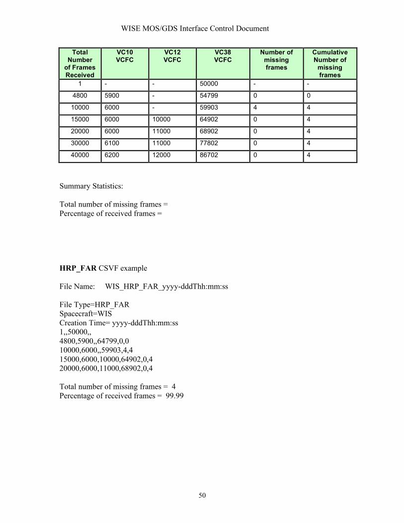
Comment: File naming convention: WIS_HRP_FAR_YYYY_DDD_HH_MM_SS.txt INTERFACE DATA DESCRIPTION WISE Frame Accountability Report (FAR) Generated by the High Rate Processor The WISE High Rate Processor (HRP) is installed at White Sands and processes transfer frames downlinked via the Ku-Band transmitter. The data stream will contain transfer frames from three virtual channels (VC10, VC12, VC38). For each downlink session, a FAR will be generated. The FAR will be used to identify missed transfer frames and assess overall data completeness. The FAR will be a comma separated value text file containing the parameters shown below in the table. A FAR will be opened when a non-idle frame is received and processed by the HRP. A line in the FAR is generated for the first appearance of a VC10 or VC12 or VCC8 transfer frame. A line in the FAR will also be generated on the reception of every 10000th frame. A line in the FAR will be generated upon receipt of the last non-idle transfer frame. The FAR will be terminated when a specified number of contiguous idle frames is received (5000 or so). The HRP will insert entries into the FAR table for “Total number of frames received and then the current values of the three VCFC for “VC10 VCFC”, “VC12 VCFC”, “VC38 VCFC”, and then the “Number of missing frames”, and then the “Cumulative number of missing frames”.
Frame Accountability Report
WISE MOS/GDS Interface Control Document
50
Total Number
of Frames Received
VC10 VCFC
VC12 VCFC
VC38 VCFC
Number of missing frames
Cumulative Number of
missing frames
1 - - 50000 - -
4800 5900 - 54799 0 0
10000 6000 - 59903 4 4
15000 6000 10000 64902 0 4
20000 6000 11000 68902 0 4
30000 6100 11000 77802 0 4
40000 6200 12000 86702 0 4
Summary Statistics: Total number of missing frames = Percentage of received frames = HRP_FAR CSVF example File Name: WIS_HRP_FAR_yyyy-dddThh:mm:ss File Type=HRP_FAR Spacecraft=WIS Creation Time= yyyy-dddThh:mm:ss 1,,50000,, 4800,5900,,64799,0,0 10000,6000,,59903,4,4 15000,6000,10000,64902,0,4 20000,6000,11000,68902,0,4 Total number of missing frames = 4 Percentage of received frames = 99.99

WISE MOS/GDS Interface Control Document
51
INTERFACE DESCRIPTION FORM Interface name: HRP_File_Summary HRP File Summary Report - A listing of files produced by the HRP during a single TDRSS contact pass EXCHANGE DESCRIPTION
Provider: HRP Consumer: WSDC
Server: HRP Client: WSDC
Protocol: File Transfer Connection initiator: HRP
Schedule: Following every Ku-Band TDRSS pass
Comment: INTERFACE DATA DESCRIPTION To be provided by 15 August 2007.

WISE MOS/GDS Interface Control Document
52
INTERFACE DESCRIPTION FORM Interface name: HRP_Status_Pkt A periodic packet generated by the HRP providing the status of the HRP. EXCHANGE DESCRIPTION
Provider: HRP Consumer: WTCCS
Server: HRP Client: WTCCS
Protocol: TCP/IP Socket Connection initiator: WTCCS
Schedule: During every Ku-Band TDRSS pass
Comment: INTERFACE DATA DESCRIPTION To be provided by 15 August 2007.
WISE MOS/GDS Interface Control Document
53
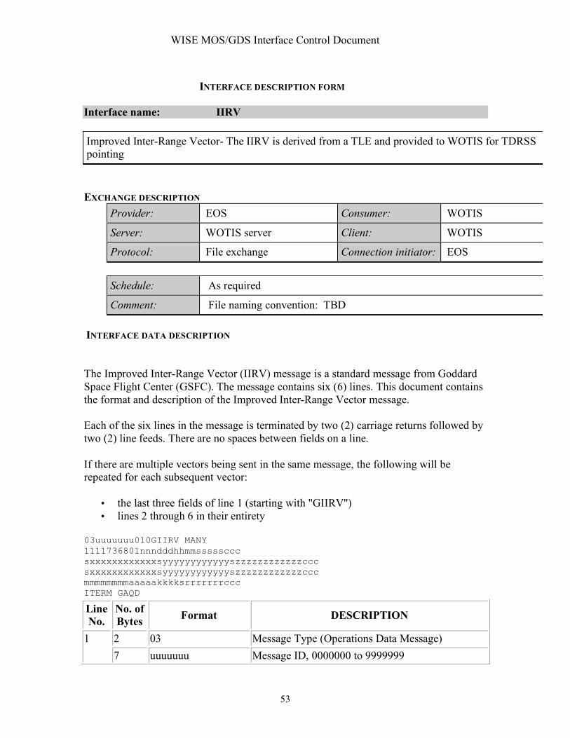
INTERFACE DESCRIPTION FORM Interface name: IIRV Improved Inter-Range Vector- The IIRV is derived from a TLE and provided to WOTIS for TDRSS pointing EXCHANGE DESCRIPTION
Provider: EOS Consumer: WOTIS
Server: WOTIS server Client: WOTIS
Protocol: File exchange Connection initiator: EOS
Schedule: As required
Comment: File naming convention: TBD INTERFACE DATA DESCRIPTION
The Improved Inter-Range Vector (IIRV) message is a standard message from Goddard Space Flight Center (GSFC). The message contains six (6) lines. This document contains the format and description of the Improved Inter-Range Vector message.
Each of the six lines in the message is terminated by two (2) carriage returns followed by two (2) line feeds. There are no spaces between fields on a line.
If there are multiple vectors being sent in the same message, the following will be repeated for each subsequent vector:
• the last three fields of line 1 (starting with "GIIRV") • lines 2 through 6 in their entirety
03uuuuuuu010GIIRV MANY 1111736801nnndddhhmmsssssccc sxxxxxxxxxxxxsyyyyyyyyyyyyszzzzzzzzzzzzccc sxxxxxxxxxxxxsyyyyyyyyyyyyszzzzzzzzzzzzccc mmmmmmmmaaaaakkkksrrrrrrrccc ITERM GAQD
Line No.
No. of Bytes Format DESCRIPTION
2 03 Message Type (Operations Data Message) 1 7 uuuuuuu Message ID, 0000000 to 9999999

WISE MOS/GDS Interface Control Document
54
1 0 Message source (Flight Dynamics Facility) 2 10 Message class (nominal) 5 "GIIRV" Message start 1 ASCII space Originator of message (GSFC)
4 "MANY" Routing indicator (multiple destinations) 1 1 Vector type (free flight, routine on-orbit) 1 1 Data source (nominal/ planning) 1 1 Transfer type (Interrange)
1 1 Coordinate system (Geocentric true-of-date rotation)
4 7368 Support Identification Code 2 01 Vehicle Identification Code
3 nnn Sequence number incremented for each vector in a set of vector data, 000 to 999
3 ddd Day of year, 001 to 366
9 hhmmsssss Vector epoch in UTC, hh = 00 to 23, mm = 00 to 59, sssss = 00000 to 59999 (milliseconds, implied decimal point three places from right)
2
3 ccc
Checksum for line 2; calculated by summing the decimal equivalent of the preceding characters in the line, counting spaces as 0 and negative signs as 1
13 sxxxxxxxxxxxx X component of the position vector in meters. s = "-" for negative sign or ASCII space for positive sign
13 syyyyyyyyyyyy Y component of the position vector in meters 13 szzzzzzzzzzzz Z component of the position vector in meters
3
3 ccc Checksum for line 3
13 sxxxxxxxxxxxx
X component of the velocity vector in meters per second, with a resolution to the nearest millimeter per second; assumed decimal point is three places from the right.
13 syyyyyyyyyyyy
Y component of the velocity vector in meters per second, with a resolution to the nearest millimeter per second; assumed decimal point is three places from the right.
4
13 szzzzzzzzzzzz
Z component of the velocity vector in meters per second, with a resolution to the nearest millimeter per second; assumed decimal point is three places from the right.

WISE MOS/GDS Interface Control Document
55
3 ccc Checksum for line 4
8 mmmmmmmm
Mass of the satellite in kilograms with a resolution to the nearest tenth of a kilogram; assumed decimal point is one place from the right. Must contain all zeros if not used.
5 aaaaa
Average satellite cross-sectional area in square meters with a resolution to the nearest hundredth of a square meter; assumed decimal point is two places from the right. Must contain all zeros if not used.
4 kkkk Dimensionless drag coefficient; assumed decimal point is two places from the right. Must contain all zeros if not used.
8 srrrrrrr
Dimensionless solar reflectivity coefficient; s = "-" for negative sign or blank for positive sign, assumed decimal point is six places from the right. May contain all zeros if not used.
5
3 ccc Checksum for line 5 5 "ITERM" Indicates end of message 1 ASCII blank 6 4 "GAQD" Originator routing
7 10 "GIIRV MANY" Identifies message start, originator and routing indicator for second vector set
8-12 same as lines 2-6 for a second vector set Second vector set
13- repeat lines 7-12 for each subsequent vector set
Additional vector sets

WISE MOS/GDS Interface Control Document
56
INTERFACE DESCRIPTION FORM Interface name: Memory_File_Load Memory Load File - Binary Memory Load file input format to the CFDP command processor EXCHANGE DESCRIPTION
Provider: EOS Consumer: WTCCS
Server: WISE Server Client: WTCCS
Protocol: File exchange Connection initiator: EOS
Schedule: As required
Comment: INTERFACE DATA DESCRIPTION The memory load file is a binary file provided for CDFP processing and uplink. The binary file is partitioned into CFDP PDU’s as described under interface CFDP_UPLINK_PDU.

WISE MOS/GDS Interface Control Document
57
INTERFACE DESCRIPTION FORM Interface name: Mission_Data_Archive_File Mission Data Archive File - Mission data file (compressed) for long term deep archive EXCHANGE DESCRIPTION
Provider: WSDC Consumer: All
Server: WSDC Client: All
Protocol: Connection initiator: All
Schedule:
Comment: File naming convention: TBS INTERFACE DATA DESCRIPTION To be provided prior to the WSDC (IPAC) CDR.

WISE MOS/GDS Interface Control Document
58
INTERFACE DESCRIPTION FORM Interface name: OEF Orbit Events File - Text file containing key spacecraft and ground events including the TDRSS pass schedule EXCHANGE DESCRIPTION
Provider: NAV Consumer: SEQ, EOS
Server: WISE Server Client: SEQ,EOS
Protocol: FTP Connection initiator: SEQ,EOS
Schedule: Weekly
Comment: File naming convention: WIS_NAV_OEF_YYYY_DDD_HH_MM_SS.txt INTERFACE DATA DESCRIPTION The WISE Orbit Events File consists of a series of header records followed by a series of data records. Section 2.2 describes the header records in detail. Section 2.3 defines all the data in the data records. Section 2.4 describes the format of the data records in detail, and Section 2.5 contains a sample file.
5.1 Header Records The header records on the WISE Orbit Events File contain all of the input data used in the WOE run that wrote the file. WOE writes this information as a series of lines of ASCII text with an asterisk (*) always appearing in column 1. The lines are free form; i.e., no particular format is assumed. The header records contain the following information:
• The name and version of the program • A list of paths to the input files used (orbit number file, leapseconds kernel, and
ephemeris files for the spacecraft, TDRS satellites, Earth, and Moon). • The start and end times of the WOE run that wrote the file as character data of the
form yyyy-dddThh:mm:ss.ffff (UTC). • A copy of the Defaults File. The Defaults File contains default values for all of
WOE’s namelist input variables. For details, see the WOE User’s Guide. In addition, other information (e.g., comments) may appear on the file.
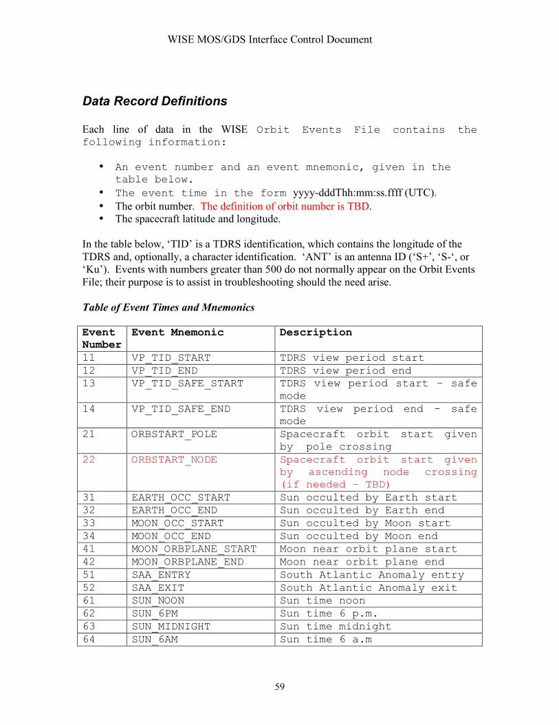
WISE MOS/GDS Interface Control Document
59
Data Record Definitions Each line of data in the WISE Orbit Events File contains the following information:
• An event number and an event mnemonic, given in the table below.
• The event time in the form yyyy-dddThh:mm:ss.ffff (UTC). • The orbit number. The definition of orbit number is TBD. • The spacecraft latitude and longitude.
In the table below, ‘TID’ is a TDRS identification, which contains the longitude of the TDRS and, optionally, a character identification. ‘ANT’ is an antenna ID (‘S+’, ‘S-‘, or ‘Ku’). Events with numbers greater than 500 do not normally appear on the Orbit Events File; their purpose is to assist in troubleshooting should the need arise. Table of Event Times and Mnemonics Event Number
Event Mnemonic Description
11 VP_TID_START TDRS view period start 12 VP_TID_END TDRS view period end 13 VP_TID_SAFE_START TDRS view period start – safe
mode 14 VP_TID_SAFE_END TDRS view period end – safe
mode 21 ORBSTART_POLE Spacecraft orbit start given
by pole crossing 22 ORBSTART_NODE Spacecraft orbit start given
by ascending node crossing (if needed – TBD)
31 EARTH_OCC_START Sun occulted by Earth start 32 EARTH_OCC_END Sun occulted by Earth end 33 MOON_OCC_START Sun occulted by Moon start 34 MOON_OCC_END Sun occulted by Moon end 41 MOON_ORBPLANE_START Moon near orbit plane start 42 MOON_ORBPLANE_END Moon near orbit plane end 51 SAA_ENTRY South Atlantic Anomaly entry 52 SAA_EXIT South Atlantic Anomaly exit 61 SUN_NOON Sun time noon 62 SUN_6PM Sun time 6 p.m. 63 SUN_MIDNIGHT Sun time midnight 64 SUN_6AM Sun time 6 a.m

WISE MOS/GDS Interface Control Document
60
71 LAT_CROSS_EQUATOR Latitude crossing measured from equator
72 LAT_CROSS_POLE Latitude crossing measured from pole
81 CONJUNC_TID_START Spacecraft-TDRS-Sun conjunction start
82 CONJUNC_TID_END Spacecraft-TDRS-Sun conjunction end
511 SUN_AVOID_TID_START Sun avoidance constraint
start 512 SUN_AVOID_TID_END Sun avoidance constraint end 513 EARTH_AVOID_TID_START Earth avoidance constraint
start 514 EARTH_AVOID_TID_END Earth avoidance constraint
end 521 SUN_YAW_TID_START Sun yaw constraint start 522 SUN_YAW_TID_END Sun yaw constraint end 531 TDRS_OCC_TID_START TDRS occulted by Earth start 532 TDRS_OCC_TID_END TDRS occulted by Earth end 541 NADIR_TID_START Nadir constraint start 542 NADIR_TID_END Nadir constraint end 551 CONE_TID_ANT_START Antenna cone angle constraint
start 552 CONE_TID_ANT_END Antenna cone angle constraint
end 561 LAT_START Latitude constraint start 562 LAT_END Latitude constraint end TDRS Identifications The following identifications consist of the ID letter (A – J) followed by the West longitude in degrees. The longitudes come from the GFSC Products Web site. TDRS-1 (A)
TDRS-3 (C)
TDRS-4 (D)
TDRS-5 (E)
TDRS-6 (F)
TDRS-7 (G)
TDRS-8 (H)
TDRS-9 (I)
TDRS-10 (J)
A049W C275W D046W E171W F174W G150W H271W I062W J041W Data Record Format
Below is a description of the format of the data on each data record. See Section 2.5 for an example.

WISE MOS/GDS Interface Control Document
61
Description of Data Record Format Column number Contents 1-3 Event number in the form NNN, right justified 4 Blank 5-26 Event time in the form yyyy-dddThh:mm:ss.ffff (UTC) 27 Blank 28-31 Orbit number in the form NNNN, right justified 32 Blank 33-38 Longitude in the form XXX.XX 39 Blank 40-45 Latitude in the form +/-XX.XX 46 Blank
47-72
Event mnemonic, left justified
Sample File
The following is an example of what the WOE Orbit Events file will look like. This example is for illustration only and does not represent actually output from WOE. An actually output file will be provided when one is available. *--------------------------------------------------------------------------------------- * WISE Orbit Events computed by WOE, Version 1.0 *------------------------------------------------------------------------ * SPK ephemeris files used: * /home/ear/woe/data/wise_tdrs_j_f.bsp * Leapseconds kernel: /home/ear/woe/data/leapseconds * All times in this file are in UTC * Start time of the run: 2009-337T00:00:00.000000 * End time of the run: 2009-355T00:00:00.000000 * (Multiple lines containing a copy of the Defaults File - TBS) *------------------------------------------------------------------------ * *NO EVENT TIME ORB LON LAT MNEMONIC *---- -------------------------- ----- -------- ------ ------------------- 11 2009-337T07:32:32.2868 125 203.56 -66.01 VP_190.4_START 21 2009-339T08:12:29.2314 125 175.02 -30.14 EARTH_OCC_START 52 2009-353T09:12:34.6578 125 191.33 -42.24 SAA_EXIT
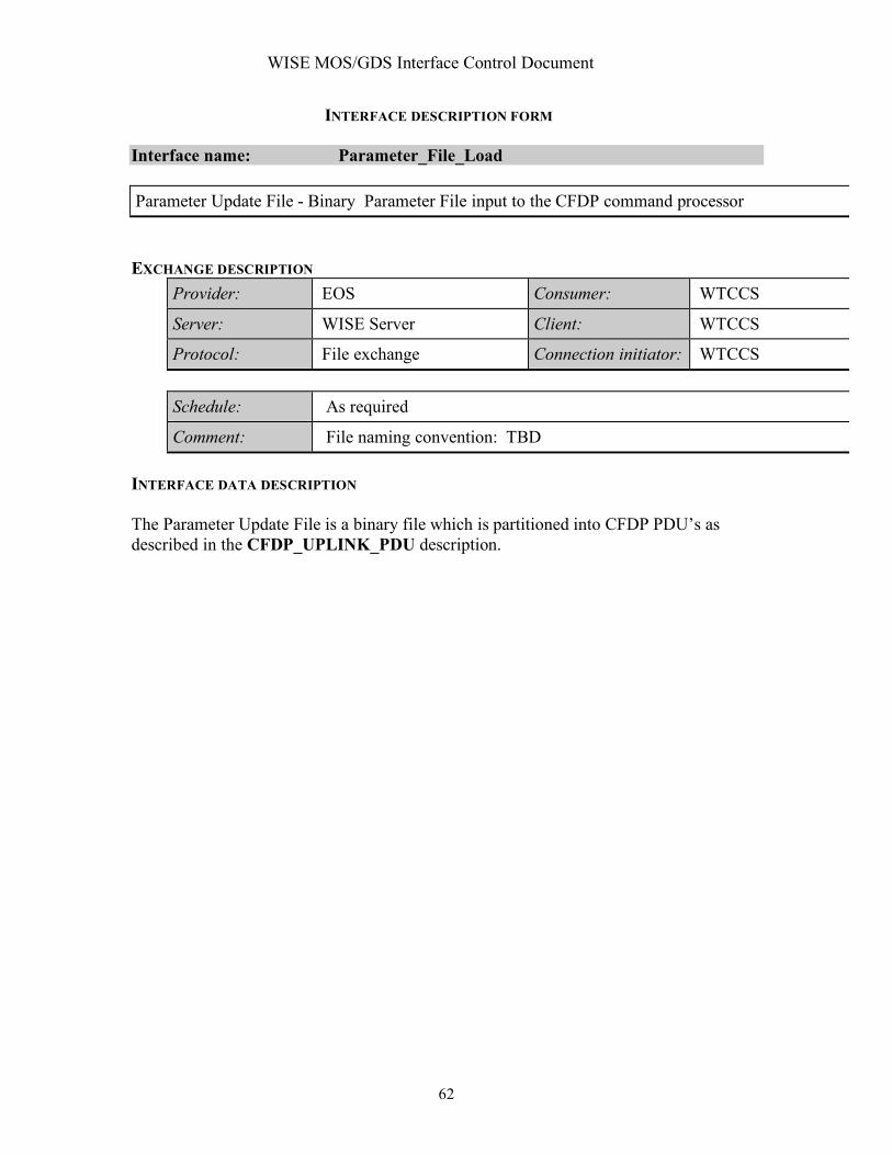
WISE MOS/GDS Interface Control Document
62
INTERFACE DESCRIPTION FORM Interface name: Parameter_File_Load Parameter Update File - Binary Parameter File input to the CFDP command processor EXCHANGE DESCRIPTION
Provider: EOS Consumer: WTCCS
Server: WISE Server Client: WTCCS
Protocol: File exchange Connection initiator: WTCCS
Schedule: As required
Comment: File naming convention: TBD INTERFACE DATA DESCRIPTION The Parameter Update File is a binary file which is partitioned into CFDP PDU’s as described in the CFDP_UPLINK_PDU description.

WISE MOS/GDS Interface Control Document
63
INTERFACE DESCRIPTION FORM Interface name: PEF Spacecraft Predicted Events File - SEQGEN output file predicting spacecraft events resulting from the nominal execution of an on-board stored sequence EXCHANGE DESCRIPTION
Provider: SEQ Consumer: All
Server: WISE Server Client: All
Protocol: FTP Connection initiator: All
Schedule: Usually weekly or whenever a SEQGEN run is made.
Comment: File naming convention: WIS_SEQ_SEQID_YYYY_DDD_HH_MM_SS.pef Where SEQID is the Sequence Identifier for this sequence product.
INTERFACE DATA DESCRIPTION
Refer to the latest version of the multi-mission SIS for the Predicted Events File, 0289-SEQ-SEQ Rev. J currently dated 15 April 2003.

WISE MOS/GDS Interface Control Document
64
INTERFACE DESCRIPTION FORM Interface name: Processed_Quick_Look_Rpt Processed Quick Look Science Report - Initial report assessing science data quality EXCHANGE DESCRIPTION
Provider: WSDC Consumer: All
Server: WSDC Server Client: All
Protocol: FTP Connection initiator: All
Schedule: Daily
Comment: File naming convention: TBD INTERFACE DATA DESCRIPTION To be provided prior to the WSDC (IPAC) CDR.

WISE MOS/GDS Interface Control Document
65
INTERFACE DESCRIPTION FORM Interface name: Processed_Sci_Data Processed Science Data - Routinely processed science data EXCHANGE DESCRIPTION
Provider: WSDC Consumer: Science Community
Server: WSDC Client: Science Community
Protocol: TBD Connection initiator: Science Community
Schedule:
Comment: File naming convention: TBD INTERFACE DATA DESCRIPTION To be provided prior to the WSDC (IPAC) CDR.

WISE MOS/GDS Interface Control Document
66
INTERFACE DESCRIPTION FORM Interface name: Rec_HK_Data Recorded Housekeeping Data File - File containing recorded housekeeping telemetry in packet format EXCHANGE DESCRIPTION
Provider: WTCCS-HRP Consumer: WTCCS
Server: HRP-RAID Client: WTCCS
Protocol: Secure file transfer Connection initiator: WTCCS
Schedule: Following each TDRSS pass
Comment: Packet files are pushed via secure file transfer to the WISE POC for processing. File naming convention: WIS_HRP_PKT_VC10_YYYY_DDD_HH_MM_SS.bin
INTERFACE DATA DESCRIPTION Recorded housekeeping data files are generated by the High Rate Data Processor installed at White Sands. Packets are extracted from VC10 transfer frames and stored in file format. Refer to the interface data description for the TLM_Packet_APID.

WISE MOS/GDS Interface Control Document
67
INTERFACE DESCRIPTION FORM Interface name: SASF Spacecraft Activity Sequence File - SEQGEN input request file containing timed commands for integration into an on-board stored sequence EXCHANGE DESCRIPTION
Provider: All Consumer: SEQ
Server: WISE Server Client: SEQ
Protocol: FTP Connection initiator: SEQ
Schedule: Provided per the Sequence Development Schedule
Comment: File naming convention: WIS_SEQ_SEQID_YYYY_DDD_HH_MM_SS.sasf Where SEQID is the Sequence Identifier for this sequence product.
INTERFACE DATA DESCRIPTION
Refer to the latest version of the multi-mission SIS for the Spacecraft Activity Sequence File, 0290-SEQ-SEQ Rev. J currently dated 30 November 2002.
WISE EXAMPLE FILE NAME: *.SASF CCSD3ZF0000100000001NJPL3KS0L015$$MARK$$; MISSION_NAME = WISE; SPACECRAFT_NAME = WISE; DATA_SET_ID = SPACECRAFT_ACTIVITY_SEQUENCE; FILE_NAME = WSEQ0601A.sasf; APPLICABLE_START_TIME = 2005-360T00:00:00.000; APPLICABLE_STOP_TIME = 2006-002T23:59:59.000; PRODUCT_CREATION_TIME = 2005-353T18:19:41; PRODUCER_ID = smalloy; SEQ_ID = WSEQ0601; HOST_ID = pinkie; CCSD3RE00000$$MARK$$NJPL3IF0M01300000001; $$WISE SPACECRAFT ACTIVITY SEQUENCE FILE
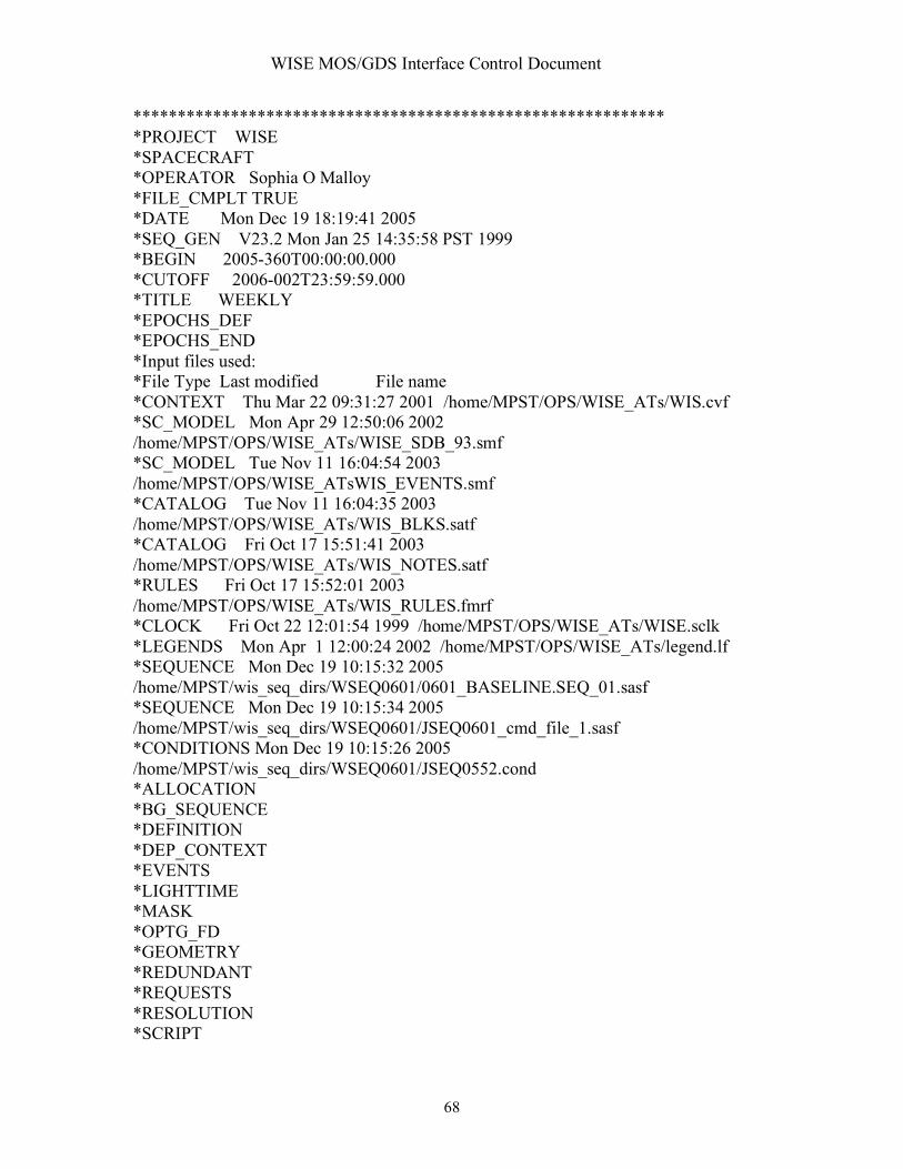
WISE MOS/GDS Interface Control Document
68
************************************************************ *PROJECT WISE *SPACECRAFT *OPERATOR Sophia O Malloy *FILE_CMPLT TRUE *DATE Mon Dec 19 18:19:41 2005 *SEQ_GEN V23.2 Mon Jan 25 14:35:58 PST 1999 *BEGIN 2005-360T00:00:00.000 *CUTOFF 2006-002T23:59:59.000 *TITLE WEEKLY *EPOCHS_DEF *EPOCHS_END *Input files used: *File Type Last modified File name *CONTEXT Thu Mar 22 09:31:27 2001 /home/MPST/OPS/WISE_ATs/WIS.cvf *SC_MODEL Mon Apr 29 12:50:06 2002 /home/MPST/OPS/WISE_ATs/WISE_SDB_93.smf *SC_MODEL Tue Nov 11 16:04:54 2003 /home/MPST/OPS/WISE_ATsWIS_EVENTS.smf *CATALOG Tue Nov 11 16:04:35 2003 /home/MPST/OPS/WISE_ATs/WIS_BLKS.satf *CATALOG Fri Oct 17 15:51:41 2003 /home/MPST/OPS/WISE_ATs/WIS_NOTES.satf *RULES Fri Oct 17 15:52:01 2003 /home/MPST/OPS/WISE_ATs/WIS_RULES.fmrf *CLOCK Fri Oct 22 12:01:54 1999 /home/MPST/OPS/WISE_ATs/WISE.sclk *LEGENDS Mon Apr 1 12:00:24 2002 /home/MPST/OPS/WISE_ATs/legend.lf *SEQUENCE Mon Dec 19 10:15:32 2005 /home/MPST/wis_seq_dirs/WSEQ0601/0601_BASELINE.SEQ_01.sasf *SEQUENCE Mon Dec 19 10:15:34 2005 /home/MPST/wis_seq_dirs/WSEQ0601/JSEQ0601_cmd_file_1.sasf *CONDITIONS Mon Dec 19 10:15:26 2005 /home/MPST/wis_seq_dirs/WSEQ0601/JSEQ0552.cond *ALLOCATION *BG_SEQUENCE *DEFINITION *DEP_CONTEXT *EVENTS *LIGHTTIME *MASK *OPTG_FD *GEOMETRY *REDUNDANT *REQUESTS *RESOLUTION *SCRIPT

WISE MOS/GDS Interface Control Document
69
*TELEMETRY *TYPEDEF *VIEWPERIOD *VIEW_FD ************************************************************ $$EOH $$EOD request(WSEQ_START, START_TIME, 2005-360T00:00:00, TITLE, "JSEQ_START", REQUESTOR, "smalloy", DESCRIPTION, "WSEQ_START", PROCESSOR, "NOTE", KEY, "SCE", LOWER_LABEL, "WSEQ_START", WORKGROUP,"MPS") activity(WSEQ_START, SCHEDULED_TIME,\0:0:0\,FROM_ACTIVITY_START, DRAW, STANDARD, BLOCK(JSEQ_START,"0601") ), end; note(1, SCHEDULED_TIME,\0:0:0\,FROM_ACTIVITY_START, TEXT,\"STORED CMD FILE: ja1_tc_tch_01_p1_2005_12_13_07_47_59.tcg"\ ), note(1.1, SCHEDULED_TIME,\0:0:0\,FROM_ACTIVITY_START, TEXT,\"START WISE CALIBRATION"\ ), command(1, SCHEDULED_TIME,\00:00:00\,FROM_ACTIVITY_START, POS1TCSTOP("24 1809C0000011A900054B00019668000000000822000AFFF5") ), command(2, SCHEDULED_TIME,\00:00:10\,FROM_PREVIOUS_START, POS1TCCAL1("36 1809C000001DA900054B000196720000000008280004C80000400400070100FC007E2B40") ), $$EOF

WISE MOS/GDS Interface Control Document
70
INTERFACE DESCRIPTION FORM Interface name: Science_Data_Archive_File Science Data Archive File - Science data file (compressed) for long term deep archive EXCHANGE DESCRIPTION
Provider: WSDC Consumer: WSDC
Server: WSDC Client: WSDC
Protocol: TBD Connection initiator: WSDC
Schedule:
Comment: File naming convention: TBD INTERFACE DATA DESCRIPTION To be provided prior to the WSDC (IPAC) CDR.

WISE MOS/GDS Interface Control Document
71
INTERFACE DESCRIPTION FORM Interface name: Science_TLM_Packet_ID
Interface Description: Science Telemetry Packet files segregated by APID/PKTID (Band) EXCHANGE DESCRIPTION
Provider: HRP Consumer: WSDC
Server: HRP Client: WSDC
Protocol: Secure FTP (push) Connection initiator: HRP
Schedule: Following each TDRSS pass, nominally 4 times daily
Comment: File naming convention: Packet file for a single ID (Band): WIS_HRP_PKT_ID_YYYY_DDD_HH_MM_SS.bin Where ID is the concatenation of the application process ID (APID) and packet ID of the packet in the file (e.g. ID = FE1A for band 1 compressed). The time field in the file name is the file creation time.
INTERFACE DATA DESCRIPTION

WISE MOS/GDS Interface Control Document
72
Science Payload TM Source Packet Format The MUB creates payload instrument data TM source packets. The Application ID (source) is used to identify that the packets were created by the MUB. The Packet ID (source) is used to identify which band (1 – 4) the instrument data is from and whether the data is compressed or uncompressed. See Error! Reference source not found. below for definitions of Application ID and Packet ID. The Source Sequence Count increments with each successive source packet created from data from each of the instrument bands. The Source Sequence Count is reset to zero for each new image cycle and is counted separately for each band. The Grouping Flags are used to designate each group of packets that comprises an image. The timestamp is constant for each group of packets that comprises an image. The Valid User Data Bytes field of the Secondary Header is populated according to how many bytes of science data are contained in the packet. All packets will be of fixed length. The final packet (i.e. Grouping Flags value is 10b) for a given image on a given band will be padded with fill bytes as necessary to complete the packet. The fill byte value is 0x5A. Figure 1 below defines the WISE Payload Instrument TM Science Data Source Packet Format. The user data size has been chosen to minimize the CCSDS source packet header overhead while providing for efficient storage of CADUs to the 128-bit wide memory of the Flash Memory Card.
Groundlink Science Data Telemetry Packet Format Bytes Bits Default Bits Comment
Version Number 3 000b Version-1 TM source packet Type Indicator 1 0b Telemetry packet Packet Secondary Header Flag 1 1b Secondary header present SCU ID 1 0b Single WISE SCU Spare
1
2 00b Spare Application ID (source) 1 8 0xFE All MUB-generated packets have APID 254 Grouping Flags 2 varies Designates grouped packets (01b - first, 00b cont., 10b last Pckt.)
Source Sequence Count 2
14 varies Counted separately for each Packet ID. Increments each Source Packet (resets to "0" for each new image cycle)
Prim
ary
Hea
der
Packet Length 2 16 0x043D Secondary header + User Data -1 (1100) Time Stamp 5 40 varies Vehicle Time Counter (Upper 40 bits)
Packet ID (source) 1 8 varies see Error! Reference source not found. for assignments
Sec.
Hdr
Valid User Data Bytes 2 16 varies # of Valid User(Science) Data Bytes (excludes fill data)
TM S
ourc
e Pa
cket
User Data 1078 8624 varies WISE Compressed Raw Pixel Data (Bands 1-4) and fill bytes as necessary to complete the last packet for a given image on a given band.
Total 1092 8736

WISE MOS/GDS Interface Control Document
73
Figure 1, WISE Payload Instrument TM Science Data Source Packet Format
Table 1 Science Data Telemetry Source Application and Packet Identifiers
Channel Compressed/Uncompress
ed
Application ID (APID)
(Telemetry Source)
Packet ID (Telemetry
Source) Pixel Data Band 1 Compressed 0xFE 0x1A Pixel Data Band 2 Compressed 0xFE 0x1B Pixel Data Band 3 Compressed 0xFE 0x1C Pixel Data Band 4 Compressed 0xFE 0x1D Pixel Data Band 1 Uncompressed 0xFE 0x2A Pixel Data Band 2 Uncompressed 0xFE 0x2B Pixel Data Band 3 Uncompressed 0xFE 0x2C Pixel Data Band 4 Uncompressed 0xFE 0x2D
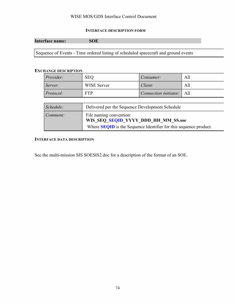
WISE MOS/GDS Interface Control Document
74
INTERFACE DESCRIPTION FORM Interface name: SOE Sequence of Events - Time ordered listing of scheduled spacecraft and ground events EXCHANGE DESCRIPTION
Provider: SEQ Consumer: All
Server: WISE Server Client: All
Protocol: FTP Connection initiator: All
Schedule: Delivered per the Sequence Development Schedule
Comment: File naming convention: WIS_SEQ_SEQID_YYYY_DDD_HH_MM_SS.soe Where SEQID is the Sequence Identifier for this sequence product.
INTERFACE DATA DESCRIPTION See the multi-mission SIS SOESIS2.doc for a description of the format of an SOE.

WISE MOS/GDS Interface Control Document
75
INTERFACE DESCRIPTION FORM Interface name: Spacecraft_Clock_File Spacecraft Clock File - Listing of correlated spacecraft clock and UTC data points EXCHANGE DESCRIPTION
Provider: EOS Consumer: WSDC,SEQ,EOS
Server: WISE Server Client: WSDC,SEQ,EOS
Protocol: FTP Connection initiator: WSDC,SEQ,EOS
Schedule: Weekly or as required depending on clock drift rate
Comment: File naming convention: WIS_EOS_clock_file_YYYY_DDD_HH_MM_XX.txt SCLKSCET.NNNNN where NNNNN is five characters in length, right justified and zerofilled on the left. It contains the alphanumeric version ID in ASCII. The version number field is initially ’00000’ and increments by one per version. Numbers may be replaced with letters if versions beyond 99999 are needed.
INTERFACE DATA DESCRIPTION
1.0 DATA FORMAT AND DEFINITION 1.0.1 SFDU Labelling The SCLKSCET file is constructed using the version 3 SFDU labelling convention as described in applicable document SFOC-1-DPS-ANY-SCLKvSCET M4 SFOC0038-04-25-02. The label for the K-object is the standard AMMOS K-object label, where the ADI is NJPL-L015. The data object uses the registered ADI of NJPL-0613. 1.0.2 File Format The SCLKSCET file is divided into four parts: the SFDU label, the Kclass header, the data internal header, and the data portions. The SCLKSCET file is encapsulated in an aggregate SFDU that also contains a K-type SFDU containing catalog information describing the data. The field-value-names used in Table 4-1 are described below. Column# Field ========================================================================= 1 blank 2-17 Effective Spacecraft Clock (SCLK0) formatted as an integer with ending decimal point.

WISE MOS/GDS Interface Control Document
76
18-19 blank 20-40 Effective Spacecraft Event Time (SCET0) yyyy-dddThh:mm:ss.sss 41 blank 42-47 Delta-UT (DUT) in atomic seconds formatted ss.sss. Delta UT is the difference between UTC and Ephemeris Time (ET) at SCET0. 48 blank 49-60 Effective SCLK rate (SCLKRATE) in atomic seconds per SCLK count floating point, blank filled. 61 blank 62 Carriage Return 63 Linefeed
EXAMPLE FILENAME: WIS_SCLKSCET.NNNNN WISE Example: CCSD3ZS00001$$sclk$$NJPL3KS0L015$$scet$$ MISSION_NAME=WISE; SPACECRAFT_NAME=WISE; DATA_SET_ID=SCLK_SCET; FILE_NAME=WIS_SCLKSCET.00020; PRODUCT_CREATION_TIME=2005-07-01T17:11:57; PRODUCT_VERSION_ID=20; PRODUCER_ID=SCT; APPLICABLE_START_TIME=1980-001T00:00:00; APPLICABLE_STOP_TIME=2010-001T00:00:00; MISSION_ID=XX; SPACECRAFT_ID=XX; CCSD3RE00000$$scet$$NJPL3IS00613$$data$$ *____SCLK0_______ ____SCET0____________ _DUT__ _SCLKRATE___ 0000000000000. 1980-001T00:00:00.000 51.184 01.000000000 0747185000000. 2003-247T23:23:07.000 64.184 00.999996741 0804634543000. 2005-181T21:32:22.843 64.184 00.999996731 CCSD3RE00000$$data$$CCSD3RE00000$$sclk$$
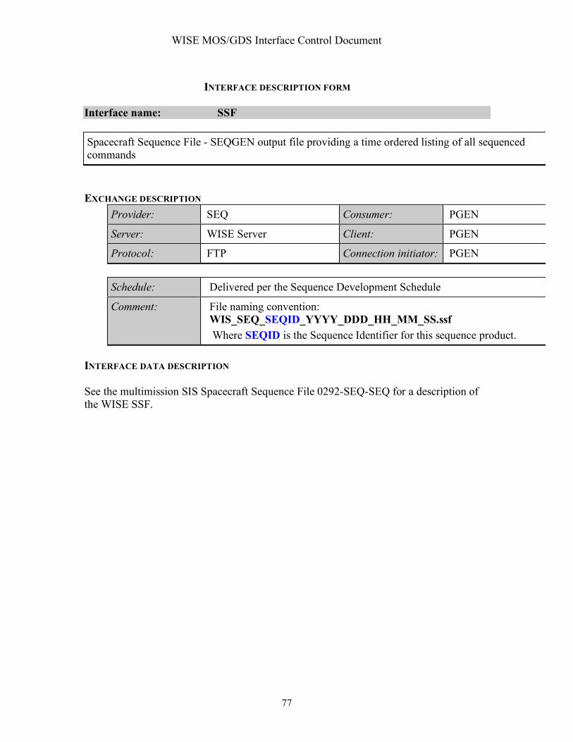
WISE MOS/GDS Interface Control Document
77
INTERFACE DESCRIPTION FORM Interface name: SSF Spacecraft Sequence File - SEQGEN output file providing a time ordered listing of all sequenced commands EXCHANGE DESCRIPTION
Provider: SEQ Consumer: PGEN
Server: WISE Server Client: PGEN
Protocol: FTP Connection initiator: PGEN
Schedule: Delivered per the Sequence Development Schedule
Comment: File naming convention: WIS_SEQ_SEQID_YYYY_DDD_HH_MM_SS.ssf Where SEQID is the Sequence Identifier for this sequence product.
INTERFACE DATA DESCRIPTION See the multimission SIS Spacecraft Sequence File 0292-SEQ-SEQ for a description of the WISE SSF.

WISE MOS/GDS Interface Control Document
78
INTERFACE DESCRIPTION FORM Interface name: Survey_Plan Survey Plan - Strategy for conducting the infrared survey derived from inputs from UCLA EXCHANGE DESCRIPTION
Provider: EOS Consumer: EOS
Server: WISE Server Client: EOS
Protocol: FTP Connection initiator: EOS
Schedule: Weekly or as required
Comment: File naming convention: WIS_EOS_SURVEY_PLAN_YYYY_DDD_HH_MM_SS.txt Date/Time is file creation time
INTERFACE DATA DESCRIPTION The Survey Plan is a text file the input parameters from the Survey Plan Input file as comments followed by the following parameters for each half orbit. Each data line has the following parameters: TIME Start times: the number of elapsed seconds since 24 May 1968, UT
00:00:00, which was JD 2440000.5
SCAN QUATERIONS Scan quaternions: the first three components are the vector part (measured in arcmin/sec); the fourth component is the scalar part.
SCAN RATES Scan rates: measured in arcmin/sec EXAMPLE FILE NAME: TBD #TOGGLE 0.2200 #MOONAVOID 1.2300 #ECLIPSEBIAS 0.0000 #BIAS 0.0000 #BIASMAX 0.0000 #DIHEDRAL 0.0000 #SCANRATE 0.0000 3.8000 0.0000 Creation date timestamp
Survey Parameters
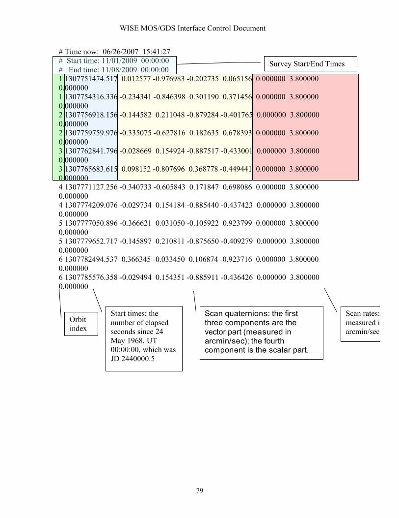
WISE MOS/GDS Interface Control Document
79
# Time now: 06/26/2007 15:41:27 # Start time: 11/01/2009 00:00:00 # End time: 11/08/2009 00:00:00 1 1307751474.517 0.012577 -0.976983 -0.202735 0.065156 0.000000 3.800000 0.000000 1 1307754316.336 -0.234341 -0.846398 0.301190 0.371456 0.000000 3.800000 0.000000 2 1307756918.156 -0.144582 0.211048 -0.879284 -0.401765 0.000000 3.800000 0.000000 2 1307759759.976 -0.335075 -0.627816 0.182635 0.678393 0.000000 3.800000 0.000000 3 1307762841.796 -0.028669 0.154924 -0.887517 -0.433001 0.000000 3.800000 0.000000 3 1307765683.615 0.098152 -0.807696 0.368778 -0.449441 0.000000 3.800000 0.000000 4 1307771127.256 -0.340733 -0.605843 0.171847 0.698086 0.000000 3.800000 0.000000 4 1307774209.076 -0.029734 0.154184 -0.885440 -0.437423 0.000000 3.800000 0.000000 5 1307777050.896 -0.366621 0.031050 -0.105922 0.923799 0.000000 3.800000 0.000000 5 1307779652.717 -0.145897 0.210811 -0.875650 -0.409279 0.000000 3.800000 0.000000 6 1307782494.537 0.366345 -0.033450 0.106874 -0.923716 0.000000 3.800000 0.000000 6 1307785576.358 -0.029494 0.154351 -0.885911 -0.436426 0.000000 3.800000 0.000000
Start times: the number of elapsed seconds since 24 May 1968, UT 00:00:00, which was JD 2440000.5
Scan quaternions: the first three components are the vector part (measured in arcmin/sec); the fourth component is the scalar part.
Scan rates: measured in arcmin/sec
Orbit index
Survey Start/End Times

WISE MOS/GDS Interface Control Document
80
INTERFACE DESCRIPTION FORM Interface name: Survey_Plan_Input Survey Plan Inputs - Strategy for conducting the infrared survey with inputs provided by UCLA EXCHANGE DESCRIPTION
Provider: SPS Consumer: SEQ
Server: WISE Server Client: SEQ
Protocol: FTP Connection initiator: SEQ
Schedule: Weekly or as required
Comment: File naming convention: WIS_SPS_INPUT_YYYY_DDD_HH_MM_SS.txt Date/Time is file creation time
INTERFACE DATA DESCRIPTION The Survey Plan Input file is an ASCII text file containing the following parameters. Start at: MM/DD/YYYY HH:MM:SS Finish at: MM/DD/YYYY HH:MM:SS TOGGLE = Parameter MOONAVOID = Parameter ECLIPSEBIAS = Parameter BIAS = Parameter BIASMAX = Parameter DIHEDRAL = Parameter SCANRATE = Parameter EXAMPLE FILE NAME: WIS_SPS_INPUT_2007_056_06_07_08.TXT
Start at: 6/26/2007 15:35:45 Finish at: 6/26/2007 15:35:45 TOGGLE = 0.22 MOONAVOID = 1.23

WISE MOS/GDS Interface Control Document
81
ECLIPSEBIAS = 0.00 BIAS = 0.00 BIASMAX = 0.00 DIHEDRAL = 0.00 SCANRATE = 0.00 3.80 0.00

WISE MOS/GDS Interface Control Document
82
INTERFACE DESCRIPTION FORM Interface name: TDRSS_GCMR TDRSS Remote Control - Socket interface for sending TDRSS remote control directives EXCHANGE DESCRIPTION
Provider: WTCCS Consumer: TDRSS-WSISK
Server: WTCCS Client: TDRSS-WSISK
Protocol: TCP-IP Socket Connection initiator: WTCCS
Schedule: Nominally four times daily during each TDRSS pass
Comment: INTERFACE DATA DESCRIPTION The format Ground Control Message Request (GCMR) is described in the document ICD Between the NCCDS and the Mission Operations Centers (451-ICD-NCCDS/MOC).

WISE MOS/GDS Interface Control Document
83
INTERFACE DESCRIPTION FORM Interface name: TDRSS_ODM TDRSS Remote Monitor Data Stream - Data stream via socket connection of TDRSS remote monitor status information EXCHANGE DESCRIPTION
Provider: TDRSS Consumer: WTCCS
Server: WDISK Client: WTCCS
Protocol: TCP/IP socket Connection initiator: WTCCS
Schedule: During each TDRSS pass
Comment: INTERFACE DATA DESCRIPTION The format of the ODM is described in the document ICD Between the NCCDS and the Mission Operations Centers (451-ICD-NCCDS/MOC).

WISE MOS/GDS Interface Control Document
84
INTERFACE DESCRIPTION FORM Interface name: TDRSS_Pass_List TDRSS Pass List - A list of TDRSS passes derived from the TDRSS Integrated Schedule EXCHANGE DESCRIPTION
Provider: SEQ Consumer: EOS, NAV
Server: WISE Server Client: EOS, NAV
Protocol: FTP Connection initiator: EOS, NAV
Schedule: Nominally weekly
Comment: File naming convention: WIS_SEQ_Pass_List_YYYY_DDD_HH_MM_SS.txt
INTERFACE DATA DESCRIPTION The TDRSS pass list is a comma separated ascii text file providing the following information: Project name TDRSS vehicle designation Pass number Time of signal acquisition Time of signal loss Downlink band Uplink enabled (Y/N) EXAMPLE FILE NAME:WIS_SEQ_PASS_LIST_2007_180_16_00_00.TXT WIS,TDRSS-9,12089,2007180172556,2007180174456,S,Y WIS,TDRSS-9,12089,2007180172556,2007180174456,Ku,Y
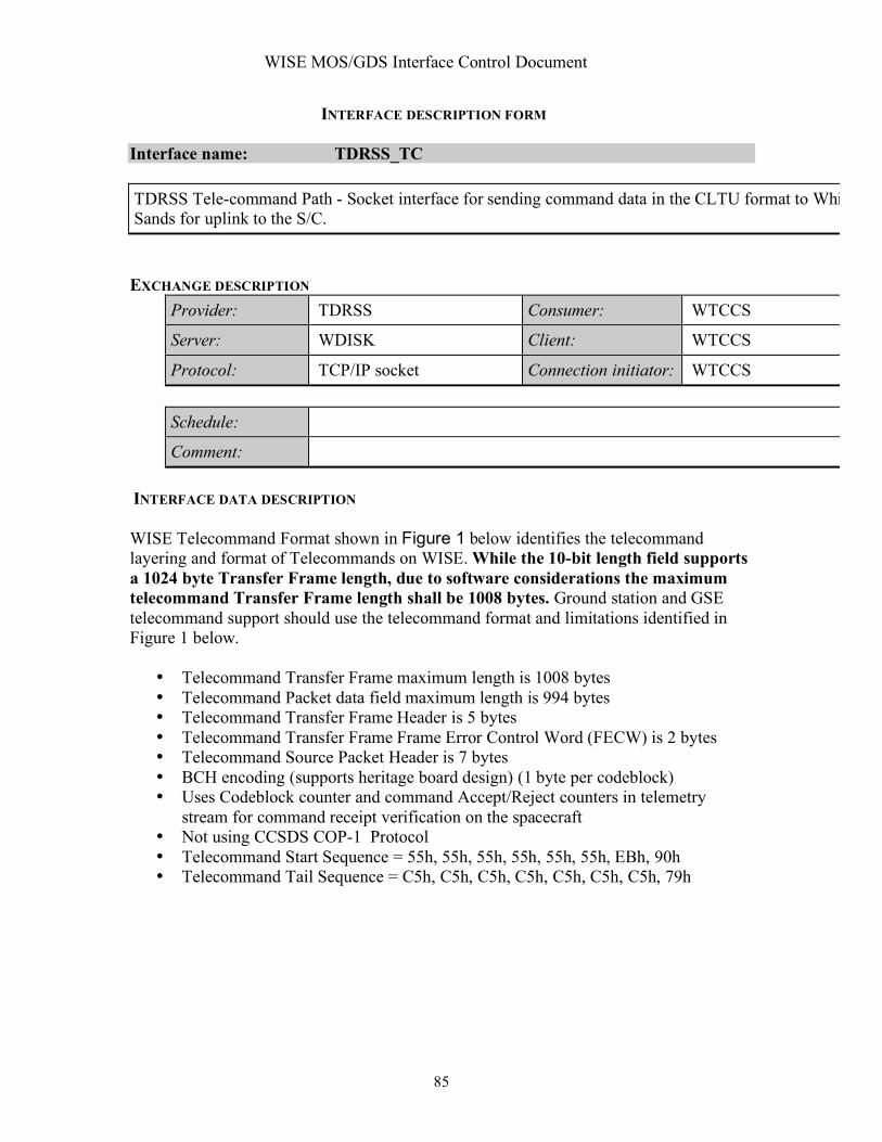
WISE MOS/GDS Interface Control Document
85
INTERFACE DESCRIPTION FORM Interface name: TDRSS_TC TDRSS Tele-command Path - Socket interface for sending command data in the CLTU format to White Sands for uplink to the S/C. EXCHANGE DESCRIPTION
Provider: TDRSS Consumer: WTCCS
Server: WDISK Client: WTCCS
Protocol: TCP/IP socket Connection initiator: WTCCS
Schedule:
Comment: INTERFACE DATA DESCRIPTION WISE Telecommand Format shown in Figure 1 below identifies the telecommand layering and format of Telecommands on WISE. While the 10-bit length field supports a 1024 byte Transfer Frame length, due to software considerations the maximum telecommand Transfer Frame length shall be 1008 bytes. Ground station and GSE telecommand support should use the telecommand format and limitations identified in Figure 1 below.
• Telecommand Transfer Frame maximum length is 1008 bytes • Telecommand Packet data field maximum length is 994 bytes • Telecommand Transfer Frame Header is 5 bytes • Telecommand Transfer Frame Frame Error Control Word (FECW) is 2 bytes • Telecommand Source Packet Header is 7 bytes • BCH encoding (supports heritage board design) (1 byte per codeblock) • Uses Codeblock counter and command Accept/Reject counters in telemetry
stream for command receipt verification on the spacecraft • Not using CCSDS COP-1 Protocol • Telecommand Start Sequence = 55h, 55h, 55h, 55h, 55h, 55h, EBh, 90h • Telecommand Tail Sequence = C5h, C5h, C5h, C5h, C5h, C5h, C5h, 79h

WISE MOS/GDS Interface Control Document
86
tm src
header
cmd source
data
cmd source
data
tc tf
header
transfer frame
data field
tc tf
header
transfer frame
data field
tm src
hdr
src pkt
data field
tm src
headerTC Source Packets
TC Transfer Frames
start
sequence
code block
dataCLTUs
Packetization Layer
(done by software )
Coding Layer
(done in CTB HW )
Transfer Layer
(done in CTB HW ) fecw
fecw
cmd source
data
tc tf
header
transfer frame
data field
tm src
header
fecw
b
c
h
code block
data
b
c
h
code block
data
b
c
h
tail
sequence
tc tf
header
transfer frame
data field
fecw
start
sequence
code block
data
b
c
h
code block
data
b
c
h
code block
data
b
c
h
tail
sequence
Figure 1, WISE Telecommand Layer Overview
Idle Pattern
... 1010101010101
0BCH
(7 bits)
1 byte 7 bytes
Data
Field
TC Codeblock
Start Seq .
x'EB 90'
2 bytes 8 bytes
TC Codeblock 1
Command Link
Transmission Unit
(CLTU)
Tail Seq .
x 'C5C5C5C5C5C5C579'... TC Codeblock N
Idle Pattern
1010101010101...
8 bytes 8 bytes
MSB LSB
TC Packet and
Segment Formats
Ver.Byp .
Flag
Cmd.
Flag
Spare Spacecraft
ID
Virtual Channel
ID
2 bytes 2 bytes
Frame LengthTransfer Frame Data Field
up to 1003 bytes
TC Transfer FrameFrame Seq .
No.
1 byte
0BCH
(7 bits)
1 byte 7 bytes
Data
FieldMSB LSB. . .
FEC
Ver. Type
2 byte up to 994 bytes
Data Field
(or CFDP PDU )
Shdr
Flag
App
ID
Seq .
Flag
s
Seq.
Count
Packet
Length
Sec. Hdr.
(Pkt ID )
2 byte 2 byte 1 byte
CCSDS Path Protocol
Data Unit (CP_PDU)
Immediate Commands
and CFDP file data units
Figure 2 WISE Telecommand Layer Details Prior to uplinking a Command Link Transmission Unit (CLTU) to the spacecraft, the ground BCH encodes sequential 56 bit data blocks of the Transfer Frame into 64 bit codeblocks. The CLTU and BCH formats are shown below. If the bits in the Transfer Frame do not total up to an even multiple of 56, the final codeblock of the CLTU is filled with alternating ones and zeros starting with a zero. The complete set of codeblocks is prepended with the CLTU Start Sequence and appended with the Tail Sequence. The CLTU is then transferred to the Physical Layer (WDISK interface) for radiation to the spacecraft at the 2000 bps uplink data rate.

WISE MOS/GDS Interface Control Document
87
START
SEQUENCE ENCODED TC DATA TAIL SEQUENCE
64 bits variable 64 bits
8 octets TC CodeBlocks 8 octets
7 PARITY CHECK BITS FILLER BIT
56 TC DATA BITS (may be
randomized)
"L" CodeBlock Length
COMMAND LINK TRANSMISSION UNIT
INFORMATION BCH ERROR CONTROL
CLTU and BCH formats

WISE MOS/GDS Interface Control Document
88
INTERFACE DESCRIPTION FORM Interface name: TDRSS_TLM TDRSS Telemetry – TDRSS telemetry stream either from WDISK or the Ku-band interface to the HRP EXCHANGE DESCRIPTION
Provider: WSC Consumer: WTCCS/HRP
Server: WSC Client: WTCCS/HRP
Protocol: TCP/IP or ECL Connection initiator: WTCCS/HRP
Schedule: During each scheduled S-band and Ku-band pass
Comment: INTERFACE DATA DESCRIPTION TDRSS provides telemetry frames as Channel Access Data Units as described in the section titled TLM_Frame_VCID.

WISE MOS/GDS Interface Control Document
89
INTERFACE DESCRIPTION FORM Interface name: TLE Two Line Element File - WISE and TDRSS TLE's defining their orbital position and rate as a function of time EXCHANGE DESCRIPTION
Provider: Stratcom Consumer: EOS, SPS
Server: TBD Client: EOS, SPS
Protocol: Web based file transfer Connection initiator: EOS, SPS
Schedule: As requested, usually daily
Comment: File naming convention: TBD INTERFACE DATA DESCRIPTION
Stratcom Two-Line Element Set Format
Data for each satellite consists of three lines in the following format:
AAAAAAAAAAAAAAAAAAAAAAAA 1 NNNNNU NNNNNAAA NNNNN.NNNNNNNN +.NNNNNNNN +NNNNN-N +NNNNN-N N NNNNN 2 NNNNN NNN.NNNN NNN.NNNN NNNNNNN NNN.NNNN NNN.NNNN NN.NNNNNNNNNNNNNN
Line 0 is a twenty-four character name (to be consistent with the name length in the NORAD SATCAT).
Lines 1 and 2 are the standard Two-Line Orbital Element Set Format identical to that used by NORAD and NASA. The format description is:
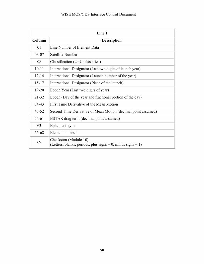
WISE MOS/GDS Interface Control Document
90
Line 1
Column Description
01 Line Number of Element Data
03-07 Satellite Number
08 Classification (U=Unclassified)
10-11 International Designator (Last two digits of launch year)
12-14 International Designator (Launch number of the year)
15-17 International Designator (Piece of the launch)
19-20 Epoch Year (Last two digits of year)
21-32 Epoch (Day of the year and fractional portion of the day)
34-43 First Time Derivative of the Mean Motion
45-52 Second Time Derivative of Mean Motion (decimal point assumed)
54-61 BSTAR drag term (decimal point assumed)
63 Ephemeris type
65-68 Element number
69 Checksum (Modulo 10) (Letters, blanks, periods, plus signs = 0; minus signs = 1)
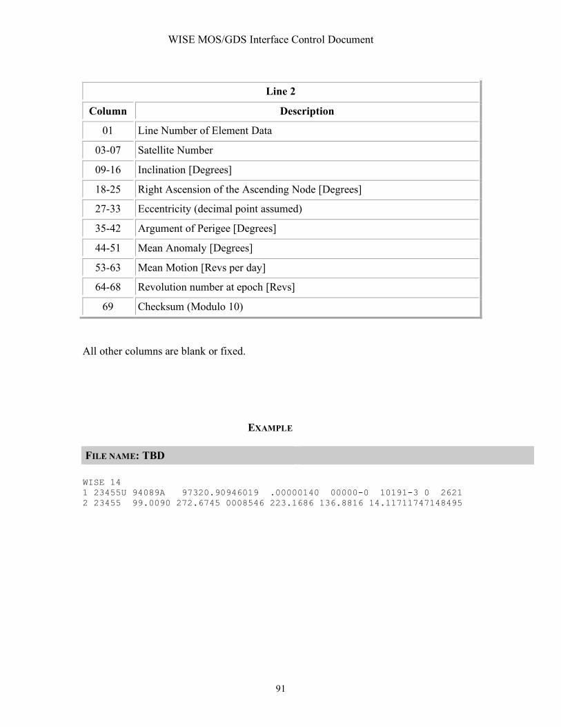
WISE MOS/GDS Interface Control Document
91
Line 2
Column Description
01 Line Number of Element Data
03-07 Satellite Number
09-16 Inclination [Degrees]
18-25 Right Ascension of the Ascending Node [Degrees]
27-33 Eccentricity (decimal point assumed)
35-42 Argument of Perigee [Degrees]
44-51 Mean Anomaly [Degrees]
53-63 Mean Motion [Revs per day]
64-68 Revolution number at epoch [Revs]
69 Checksum (Modulo 10)
All other columns are blank or fixed.
EXAMPLE FILE NAME: TBD WISE 14 1 23455U 94089A 97320.90946019 .00000140 00000-0 10191-3 0 2621 2 23455 99.0090 272.6745 0008546 223.1686 136.8816 14.11711747148495

WISE MOS/GDS Interface Control Document
92
INTERFACE DESCRIPTION FORM Interface name: TLM_CSVF Telemetry Comma Separated Value File - Comma Separated Value Files containing selected engineering data channels EXCHANGE DESCRIPTION
Provider: EOS Consumer: WSDC,SDL
Server: WISE Server Client: WSDC,SDL
Protocol: FTP Connection initiator: WSDC,SDL
Schedule: Following each TDRSS pass
Comment: File naming convention: WIS_WTCCS_TYPE_YYYY_DDD_HH_MM_SS.csv Where TYPE identifies the data set being converted into CSV format. Data set types are TBD. Time in the file name is file creation time.
INTERFACE DATA DESCRIPTION Housekeeping telemetry parameters are extracted from housekeeping telemetry packets, converted from raw values to converted values and provided to users in the form of comma separated value files (CSVF). The file contains no header. Each line in the CSVF has four values separated by commas. The values are specified in the following table: Position Value Description First Time Time tag from the telemetry packet from which the
telemetry parameter was extracted. The time format is the CCSDS ASCII Time Code B: YYYY-DDDThh:mm:ss.ddd
Second TLM Mnemonic Telemetry mnemonic as specified in the TLM data base Third Raw Value Raw telemetry value in decimal including floating point
decimal values Fourth Converted value Converted raw value from the telemetry data base. The
converted value may be in engineering units or a text string. If no conversion algorithm is specified in the TLM data base, the raw value is repeated.
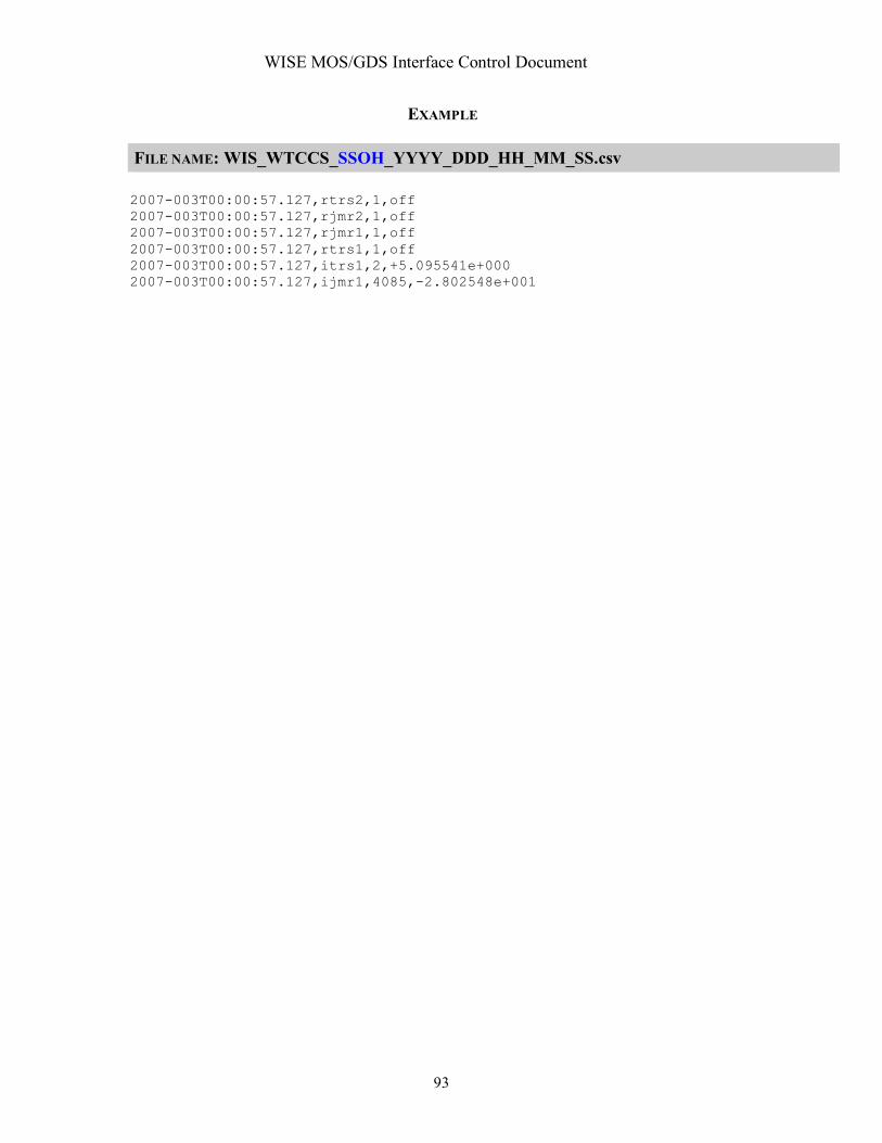
WISE MOS/GDS Interface Control Document
93
EXAMPLE FILE NAME: WIS_WTCCS_SSOH_YYYY_DDD_HH_MM_SS.csv 2007-003T00:00:57.127,rtrs2,1,off 2007-003T00:00:57.127,rjmr2,1,off 2007-003T00:00:57.127,rjmr1,1,off 2007-003T00:00:57.127,rtrs1,1,off 2007-003T00:00:57.127,itrs1,2,+5.095541e+000 2007-003T00:00:57.127,ijmr1,4085,-2.802548e+001
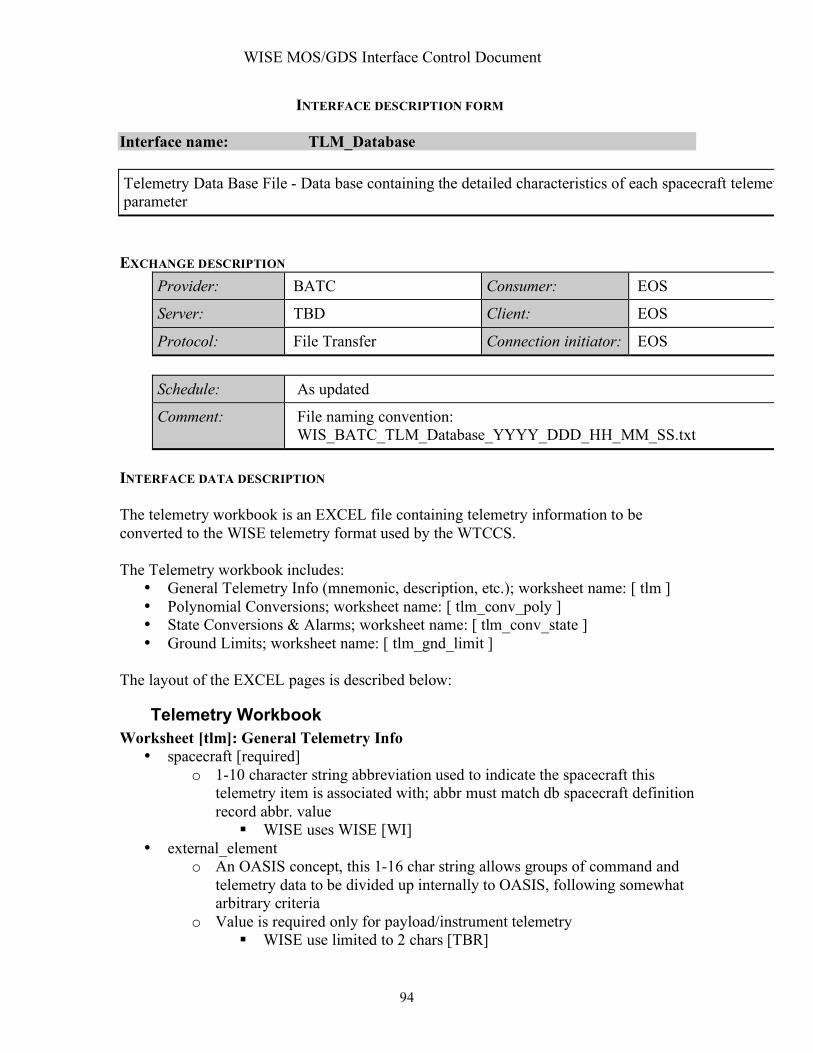
WISE MOS/GDS Interface Control Document
94
INTERFACE DESCRIPTION FORM Interface name: TLM_Database Telemetry Data Base File - Data base containing the detailed characteristics of each spacecraft telemetry parameter EXCHANGE DESCRIPTION
Provider: BATC Consumer: EOS
Server: TBD Client: EOS
Protocol: File Transfer Connection initiator: EOS
Schedule: As updated
Comment: File naming convention: WIS_BATC_TLM_Database_YYYY_DDD_HH_MM_SS.txt
INTERFACE DATA DESCRIPTION The telemetry workbook is an EXCEL file containing telemetry information to be converted to the WISE telemetry format used by the WTCCS. The Telemetry workbook includes:
• General Telemetry Info (mnemonic, description, etc.); worksheet name: [ tlm ] • Polynomial Conversions; worksheet name: [ tlm_conv_poly ] • State Conversions & Alarms; worksheet name: [ tlm_conv_state ] • Ground Limits; worksheet name: [ tlm_gnd_limit ]
The layout of the EXCEL pages is described below:
Telemetry Workbook Worksheet [tlm]: General Telemetry Info
• spacecraft [required] o 1-10 character string abbreviation used to indicate the spacecraft this
telemetry item is associated with; abbr must match db spacecraft definition record abbr. value
WISE uses WISE [WI] • external_element
o An OASIS concept, this 1-16 char string allows groups of command and telemetry data to be divided up internally to OASIS, following somewhat arbitrary criteria
o Value is required only for payload/instrument telemetry WISE use limited to 2 chars [TBR]

WISE MOS/GDS Interface Control Document
95
• app_id [required] o The application ID or reserved number (value must be unique per
spacecraft) o Integer values 1 – 255
WISE reserve 255 for the CTB WISE reserves 254 for the MUB [TBR]
• pkt_id [required] o The packet ID (value must be unique per application) o Integer values 1 – 255; blocks are reserved for monitor and monitor agent
packets • pkt_name
o [optional] The name of the packet; informational only o String; 1-80 char. max
• fsw_var_name [required] o The variable name corresponding to this telemetry item’s packet variable
name; [if the packet variable was an array, this name is used in conjunction with the next two array dimension index values to specify the exact packet variable in question]
o If this is a flight software packet, this name is the actual fsw variable name o In order for a telemetry item to be successfully imported into the database,
the fsw_var_name (in conjunction with any array indexes) MUST match up with a packet variable; otherwise the spreadsheet row will be rejected
• array_d1_index o An integer indicating the corresponding packet variable’s first dimensional
array index (if applicable) o (all packet variables that are arrays must be "unwound" in telemetry
definitions; one telemetry item per array item) • array_d2_index
o An integer indicating the corresponding packet variable’s second dimensional array index (if applicable)
o (all packet variables that are arrays must be "unwound" in telemetry definitions; one telemetry item per array item)
• data_type o The packet variable’s primitive data type: accepted values are BIT,
BOOL8, INT8, INT16, INT32, FLT32, FLT64, STRING, UINT8, UINT16, UINT32
o The data type will be automatically determined from the packet variable definition, unless this is a header tlm item; in which case it must be specified
• bit_length o This integer provides additional bit size information for BIT and STRING
data types o The value will be automatically determined from the packet variable
definition for BIT and STRING data types, unless this is a header tlm item; in which case it must be specified for BIT and STRING header tlm
• order

WISE MOS/GDS Interface Control Document
96
o [optional] An integer representing the order of the telemetry item within the packet; numbering starts at zero
o The order is determined from the packet variable definition order • mnemonic [required]
o The unique 1-12 char ground system identifier for this telemetry point (note: 12 is an OASIS limitation)
o alpha-numeric and underscore chars are allowed, no spaces o naming conventions are program specific; DI uses an additional 3 char
prefix to specify the OASIS ext_element within the mnemonic bringing the allowed character total to 15; this type of mnemonic is spit into its parts during exports for OASIS
• new_mnemonic o This is used when changing an existing mnemonic (useful for a
before/after mnemonic log) o Any values entered here must follow the same rules as for the mnemonic
field • channel_id
o [optional] Not used on WISE • start_bit
o [optional] An integer representing the start bit location within the packet for this telemetry item
o Only required for decommutating data out of the packet header, all other start bit values are automatically calculated by the db based on tlm order and data type
o For header tlm, use the program's packet header implementation definition to determine the start bit location of the data you wish to decom; also determine the size of the data type you need to store this header data and enter an appropriate data type in the data_type field
• min_value o [optional] Minimum tlm value; if not specified, data type default is used o If a polynomial conversion is supplied, applies to the converted range o Decimal and hexadecimal values are allowed; specify hex values with a
"x" prefix, ex: xF5CF • max_value
o [optional] Maximum tlm value; if not specified, data type default is used o If a polynomial conversion is supplied, applies to the converted range o Decimal and hexadecimal values are allowed; specify hex values with a
"x" prefix, ex: xF5CF • eu
o [optional] Engineering units for the telemetry item; valid EU list is project/ground system specific (SEC, V, C, etc.)
o Whenever EU units are supplied, the ground system will also need a polynomial conversion definition to convert from the raw DN value to the EU value; if not specified, the default identity conversion is used
• display_format

WISE MOS/GDS Interface Control Document
97
o [optional] Fortran-style format used to display telemetry values on the ground systems
o If not specified, a default based on data type will be used • export_to_ground
o TRUE/FALSE: set to TRUE if the ground system needs to be able to decom this particular telemetry item (sometimes spares are defined); automatically set to FALSE if mnemonic = 1-NOT_USED
o With the current implementation, EVERY telemetry packet variable needs a telemetry item definition, even if it is not currently going to be used by the ground system. These "dummy" tlm ensure that the start bit in packet locations for all subsequent tlm items are calculated correctly.
o Default = TRUE • flight_conv_dn_to_eu (DI only, not used on Kepler, OE or WISE)
o TRUE/FALSE: set to TRUE if the telemetry value will be converted onboard; otherwise any conversions will be handled by the ground system
o When TRUE, a polynomial conversion definition must also be supplied. The associated polynomial conversion definitions will be automatically added to a conversion *.sasf file for each application that requires onboard conversion of raw DN values into EU values
o Default = FALSE • tlm_description [required]
o A one line short description describing the telemetry item (~80 chars); up to 60 chars are included in OASIS exports
• tlm_notes o [optional] larger free-form text field used to capture any notes about this
telemetry measurement (3000 chars) • tlm_hyperlink
o [optional] text field used to store the URL of an online document that would be a useful reference
• test_notes o [optional] text field used to store testing notes
• 1553_address o [optional] text field for storing a 1553 address
Worksheet [tlm_conv_poly]: Polynomial Conversions
• spacecraft [required] o 1-10 character string abbreviation used to indicate the spacecraft this
telemetry item is associated with; abbr must match db spacecraft definition record abbr. value
WISE uses WISE [WI] • external_element
o An OASIS concept, this 1-16 char string allows groups of command and telemetry data to be divided up internally to OASIS, following somewhat arbitrary criteria
o Value is required only for payload/instrument telemetry WISE use limited to 2 chars [TBR]

WISE MOS/GDS Interface Control Document
98
• app_id [required] o The application ID or reserved number (value must be unique per
spacecraft) o Integer values 1 – 255
WISE reserve 255 for the CTB WISE reserves 254 for the MUB [TBR]
• pkt_id [required] o The packet ID (value must be unique per application) o Integer values 1 – 255; blocks are reserved for monitor and monitor agent
packets • TLM_order
o An integer representing the order of the telemetry item within the packet; numbering starts at zero
o The order is determined from the packet variable definition order • TLM_mnemonic [required]
o The unique 1-12 char ground system identifier for this telemetry point (note: 12 is an OASIS limitation)
o alpha-numeric and underscore chars are allowed, no spaces o naming conventions are program specific; DI uses an additional 3 char
prefix to specify the OASIS ext_element within the mnemonic bringing the allowed character total to 15; this type of mnemonic is spit into its parts during exports for OASIS
• segment_number [required] o An integer (starting with 1) representing a tlm value graph segment over
which this polynomial conversion Is applicable (if only one segment is defined, use default of 1)
o WISE allows only one segment to be defined per tlm item. • lower_bound
o Float value indicating lower boundary of segment (only required for multi-segmented polynomial conversions)
• upper_bound o Float value indicating upper boundary of segment (only required for multi-
segmented polynomial conversions) • c0 - c5
o Float values representing the coefficients of up to a 5th order polynomial equation
o c0 and c1 are required; other coefficients must be provided up to highest order being defined
o The DN to EU conversion equation: EU = c0 + c1(DN) + c2(DN^2) + c3(DN^3) + c4(DN^4) + c5(DN^5)
Worksheet [tlm_conv_state]: State Conversions and Alarms
• spacecraft [required] o 1-10 character string abbreviation used to indicate the spacecraft this
telemetry item is associated with; abbr must match db spacecraft definition record abbr. value

WISE MOS/GDS Interface Control Document
99
• WISE uses WISE [WI] • external_element
o An OASIS concept, this 1-16 char string allows groups of command and telemetry data to be divided up internally to OASIS, following somewhat arbitrary criteria
o Value is required only for payload/instrument telemetry • WISE use limited to 2 chars [TBR]
• app_id [required] o The application ID or reserved number (value must be unique per
spacecraft) o Integer values 1 – 255
• WISE reserve 255 for the CTB • WISE reserves 254 for the MUB [TBR]
• pkt_id [required] o The packet ID (value must be unique per application) o Integer values 1 – 255; blocks are reserved for monitor and monitor agent
packets • TLM_order
o An integer representing the order of the telemetry item within the packet; numbering starts at zero
o The order is determined from the packet variable definition order • TLM_mnemonic [required]
o The unique 1-12 char ground system identifier for this telemetry point (note: 12 is an OASIS limitation)
o alpha-numeric and underscore chars are allowed, no spaces o naming conventions are program specific; DI uses an additional 3 char
prefix to specify the OASIS ext_element within the mnemonic bringing the allowed character total to 15; this type of mnemonic is spit into its parts during exports for OASIS
• state_value [required] o An integer representing telemetry item value for this state; unique per tlm
item (note that if the integer is stored as text in Excel, the import of this conversion will fail)
o Valid range may be limited by ground system, otherwise range is based on user specified tlm range or data type defaults (note that Excel assigns a numeric value to the strings "True" and "False"; left-justify these strings to avoid this)
• state_name [required] o A string representing the name of this state o Max length is limited by ground systems, alphanumeric, no spaces,
naming conventions are program specific • state_alarm
o [optional] Used by ground systems to specify what (if any) alarm to associate with recieving this state
o Valid values are GOOD (green), CAUTION (yellow), BAD (red) o If not specified, default is GOOD (no alarm)

WISE MOS/GDS Interface Control Document
100
Worksheet [tlm_gnd_limits]: Ground Limits
• spacecraft [required] o 1-10 character string abbreviation used to indicate the spacecraft this
telemetry item is associated with; abbr must match db spacecraft definition record abbr. value
• WISE uses WISE [WI] • external_element
o An OASIS concept, this 1-16 char string allows groups of command and telemetry data to be divided up internally to OASIS, following somewhat arbitrary criteria
o Value is required only for payload/instrument telemetry • WISE use limited to 2 chars [TBR]
• app_id [required] o The application ID or reserved number (value must be unique per
spacecraft) o Integer values 1 – 255
• WISE reserve 255 for the CTB • WISE reserves 254 for the MUB [TBR]
• pkt_id [required] o The packet ID (value must be unique per application) o Integer values 1 – 255; blocks are reserved for monitor and monitor agent
packets • TLM_order
o An integer representing the order of the telemetry item within the packet; numbering starts at zero
o The order is determined from the packet variable definition order • TLM_mnemonic [required]
o The unique 1-12 char ground system identifier for this telemetry point (note: 12 is an OASIS limitation)
o alpha-numeric and underscore chars are allowed, no spaces o naming conventions are program specific; DI uses an additional 3 char
prefix to specify the OASIS ext_element within the mnemonic bringing the allowed character total to 15; this type of mnemonic is spit into its parts during exports for OASIS
• ground_system [required] o A string representing the abbr. of the ground system this limit applies to o Valid values are OASIS
• limit_type [required] o A string indicating when this limit is applicable. This allows groups of
limits to be defined that are applicable at different times. o Valid values are FLIGHT,INIT,TEST (default is FLIGHT) o WISE only uses FLIGHT
• yellow_limit_type | red_limit_type o A string indicating how to interpret the tlm range values o Only EXCLUSIVE is currently supported: (.. RL .. YL .. YH .. RH ..)

WISE MOS/GDS Interface Control Document
101
• yellow_low | red_low o For the EXCLUSIVE case, everything < value will be flagged by ground
system as yellow | red alarm • yellow_high | red_high
o For the EXCLUSIVE case, everything > value will be flagged by ground system as yellow | red alarm

WISE MOS/GDS Interface Control Document
102
INTERFACE DESCRIPTION FORM Interface name: TLM_Frame_VCID RAW Telemetry Frame Files - Files of Ku-band CADU transfer frames or S-Band VCDU frame files EXCHANGE DESCRIPTION
Provider: BATC Consumer: EOS
Server: TBD Client: EOS
Protocol: FTP Connection initiator: EOS
Schedule: As requested
Comment: File naming convention: WIS_HRP_CADU_YYYY_DDD_HH_MM_SS.bin for CADU’s stored by the HRP WIS_WTCCS_FRM_VCXX_YYYY_DDD_HH_MM_SS.bin where VCXX is the virtual channel ID for the frames in the file.
INTERFACE DATA DESCRIPTION

WISE MOS/GDS Interface Control Document
103
WISE Telemetry Protocol Overview - Version-2; GRADE-2 (WITHOUT INSERT , SLS MULTIPLEXING SERVICE )
Physical Layer :
Version -1 Telemetry Packet
Packet Sequence Control Packet Length
16b
Secondary Header(8 bytes )
User Data
Field
1 to 1078 bytes
(Eng . Data uses
OE max of 994 )
Version
‘ 000’3b
Type
‘0’1b
SecondaryHdr Flag
1b
APID11b Sequence
Flag
2b
Source Sequence Count
14b
Primary Header (2 bytes)
SCUID1b
Spare2b
APID8b
Packet Identification
TimeStamp
40b
Packet ID
8b
Routing ID
APID
8b
PKTID
8b
VCDU Data Field1094 Bytes (no error control bytes )
VCDU (Virtual Channel Data Unit - 1100 Bytes )
VCDU Primary Header
Version
#
2b
SCUID
8b
VCDU ID Virtual Channel
Unit Counter
24b
Signaling
Field
8b
VCID
6b
CADU (1264 Bytes)
CVCDU (Coded Virtual Data Unit ) (1260 Bytes) Sync
Marker0x1 ACFFC1D
VCDU (Virtual Channel Data Unit )(1100 Bytes )
Reed-Solomon( 160 Bytes I = 5 )
M_PDU (Multiplexing Protocol Data Unit - 1094 bytes)
M_PDU Header M_PDU packet zone (1092 bytes )
End of Previous
CCSDS Packet
#K
Spare
5b
First Header Pointer
11b
CCSDS Packet
#K + 1
CCSDS Packet
#M
Start of
CCSDS Packet
#M + 1
Figure 5.1-1, WISE Telemetry Layer Details
The WISE CADU is sized so that it is a multiple of 16 bytes (128 bits) to facilitate storage of data to the Flash Memory Card (FMC), which is 128-bit wide (144 bits with EDAC) flash memory. This requires that the technique of “Virtual Fill” be used when generating Reed-Solomon Check Bytes. WISE uses version-2, grade-2 CCSDS TM Transfer Frames (VCDUs) with Multiplexing Protocol Data Units (M-PDUs). Version-2 allows up to 64 virtual channel IDs. WISE is using Reed-Solomon encoding and randomization. WISE limits the Version-1 TM source packet user data field size to 1078 bytes so that there is always a packet header in the M_PDU packet zone. This is done to

WISE MOS/GDS Interface Control Document
104
minimize data loss should an outage occur in the downlink data stream. WISE uses CCSDS File Delivery Protocol (CFDP) for file storage downloads and uploads.
CCSDS TM Source packets on WISE are Version 11, comprised of a 6 byte primary header (which includes the APID and packet length), an 8 byte secondary header (packet time-tag & APID and pkt ID routing fields), and a data field. The CCSDS protocol permits the data field to be up to 65,528 bytes in length, but the WISE program will limit the software generated telemetry data field to 994 (to maximize OE heritage) bytes. The hardware generated transfer frames will always have 1078 bytes of User Data field. Summary of WISE CCSDS Coding layer processing:
• Reed-Solomon Encoding • Randomization • Using Attached Sync Marker (ASM) 4 bytes = 1ACFFC1Dh • No Encryption in transponder hardware • Using TM “Fill” Transfer Frames
CCSDS source packets are used internal to the flight software to pass information between flight software applications. Telemetry source packets sent to the ground use the same format as internal messages. Telecommand source packets get converted to the internal source packet format on arrival by the flight software and are time stamped with the most significant 40 bits of the 52 bit Vehicle Time Code. The time stamp field resolution is 10 milliseconds. The time stamp references when the telemetry packet is assembled by the sending SW application and when a telecommand is received by the flight software. Expanded addressing is provided by additional packet and application ID fields located in the secondary header. Source and destination application and packet IDs are 8 bits long, providing up to 256 applications, 256 packet definitions per application.
1 CCSDS 701.0-B-3 BLUE BOOK - p 5.3.8.2.2.2.a

WISE MOS/GDS Interface Control Document
105
INTERFACE DESCRIPTION FORM Interface name: TLM_Packet_ID Telemetry Extracted Packet Files – Non-Science telemetry packets extracted from KU-band telemetry stream by the high rate processor and by WTCCS for the S-band telemetry link. . EXCHANGE DESCRIPTION
Provider: WTCCS/HRDP Consumer: WTCCS
Server: WTCCS/HRDP Client: WTCCS
Protocol: Secure File Transfer Connection initiator: WTCCS
Schedule: During each TDRSS pass
Comment: File naming convention: Packet file for a single ID packet: WIS_WTCCS_PKT_ID_YYYY_DDD_HH_MM_SS.bin WIS_HRP_PKT_ID_YYYY_DDD_HH_MM_SS.bin Where ID is the concatenation of the application process ID (APID) and packet ID of the packet in the file. Packet file for all packets from a single virtual channel: WIS_WTCCS_PKT_VCXX_YYYY_DDD_HH_MM_SS.bin WIS_HRP_PKT_VCXX_YYYY_DDD_HH_MM_SS.bin Where VCXX is the virtual channel ID of the transfer from which the packets were extracted.
INTERFACE DATA DESCRIPTION Telemetry packets are extracted from transfer frames and stored in a file format. There may be a single ID packet in a file or a file of all the packets from a virtual channel. A Telemetry Source Packet is a data unit which encapsulates a block of observational data which may include ancillary data and which may be directly interpreted by the receiving end application process. This layer is also referred to as a CCSDS Path Protocol Data Unit (CP_PDU). WISE defines the Application Process Identifier and Secondary Header in the version-1 telemetry source packet format as shown below. This applies to both WISE spacecraft telemetry and the WISE payload science telemetry.

WISE MOS/GDS Interface Control Document
106
PACKET DATA
FIELD
VERSION
NO.
PACKET
DATA
LENGTH
TIM E
STAM P PACKET ID
SOURCE DATA
TYPE
INDI-
CATOR
PCKT. SEC.
HDR.
FLAG
GROUPING
FLAGS
SOURCE
SEQUENCE
COUNT
APP. ID PACKET ID
0=TLM
1=TC
SCU ID SPARE APP.ID
0=SCU-A
1=SCU-B
Telemetry
Source
Vehicle
Time
Code
Telemetry
Source
Telemetry
Destination
Telemetry
Destination
1 - 994 Bytes for
FSW generated
packets or
1078 bytes for
Science Data
Default:
000 0 1 0 0 varies 11 varies varies varies varies varies varies varies
3 bits 1 bit 1 bit 1 bit 2 bits 8 bits 2 bits 14 bit 16 bits 40 bits 8 bits 8 bits 8 bits Flexible
2 Octets 5 Octets 1 Octet 1 Octet 1 Octet 1 to 1078 Octets
TM SOURCE PACKET
APPLICATION PROCESS IDENTIFIER
2 Octets 2 Octets
PACKET PRIM ARY HEADER PACKET SECONDARY HEADER
PACKET IDENTIFICATION
PACKET SEQUENCE
CONTROL ROUTING ID
WISE TM Source Packet Format
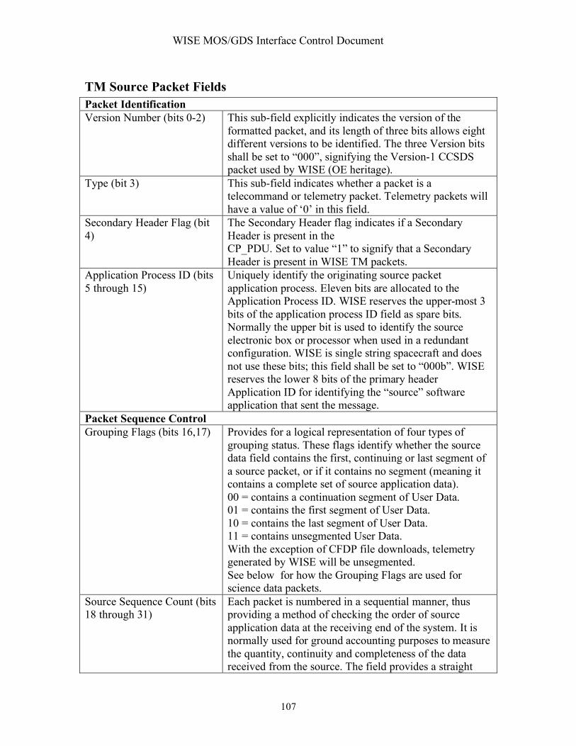
WISE MOS/GDS Interface Control Document
107
TM Source Packet Fields Packet Identification Version Number (bits 0-2) This sub-field explicitly indicates the version of the
formatted packet, and its length of three bits allows eight different versions to be identified. The three Version bits shall be set to “000”, signifying the Version-1 CCSDS packet used by WISE (OE heritage).
Type (bit 3) This sub-field indicates whether a packet is a telecommand or telemetry packet. Telemetry packets will have a value of ‘0’ in this field.
Secondary Header Flag (bit 4)
The Secondary Header flag indicates if a Secondary Header is present in the CP_PDU. Set to value “1” to signify that a Secondary Header is present in WISE TM packets.
Application Process ID (bits 5 through 15)
Uniquely identify the originating source packet application process. Eleven bits are allocated to the Application Process ID. WISE reserves the upper-most 3 bits of the application process ID field as spare bits. Normally the upper bit is used to identify the source electronic box or processor when used in a redundant configuration. WISE is single string spacecraft and does not use these bits; this field shall be set to “000b”. WISE reserves the lower 8 bits of the primary header Application ID for identifying the “source” software application that sent the message.
Packet Sequence Control Grouping Flags (bits 16,17) Provides for a logical representation of four types of
grouping status. These flags identify whether the source data field contains the first, continuing or last segment of a source packet, or if it contains no segment (meaning it contains a complete set of source application data). 00 = contains a continuation segment of User Data. 01 = contains the first segment of User Data. 10 = contains the last segment of User Data. 11 = contains unsegmented User Data. With the exception of CFDP file downloads, telemetry generated by WISE will be unsegmented. See below for how the Grouping Flags are used for science data packets.
Source Sequence Count (bits 18 through 31)
Each packet is numbered in a sequential manner, thus providing a method of checking the order of source application data at the receiving end of the system. It is normally used for ground accounting purposes to measure the quantity, continuity and completeness of the data received from the source. The field provides a straight

WISE MOS/GDS Interface Control Document
108
sequential count to modulo 16,384. WISE uses the packet sequence control fields for retrieving stored state of health data from non-volatile memory and reassembly on the ground. The memory and data manager software application are responsible for populating these fields.
Packet Length (bits 32 through 47)
The last major field of the primary header delimits the boundaries of the packet. The 16 bit Packet Length field contains a sequential binary count “C” which expresses the length (in octets) of the remainder of the CP_PDU that follows this field. The value of “C” is the number of remaining octets minus one.
Secondary Header The secondary header must appear in every frame transmitted through a physical data channel, and its length must also be fixed. WISE uses the secondary header to provide timestamp and addressing fields.
Time stamp The time stamp contains the most significant 40 bits of the 52 bit Vehicle Time Code, providing 10-millisecond resolution. The time stamp identifies when the telemetry packet was assembled by the source FSW application.
Source Packet ID (bits 88 through 95)
The source packet ID field is in the secondary header to allow for expanded addressing, and identifies the originating FSW application.
Routing ID Destination Application ID (bits 96 through 103)
The secondary header application ID identifies the destination application within the flight or ground software. WISE FSW will use the value “6” as the destination application ID for ground software. The CTB uses 0xFF and the MUB uses 0xFE.
Destination Packet ID (bits 104 through 111)
The secondary header destination packet ID identifies the destination packet. WISE will use this field to identify the VC on which the packet is sent. The CTB and MUB duplicate the Source Packet ID in this field.
Source Data Following the secondary header, the source data sub-field contains source application data generated by the application process identified in the primary header.

WISE MOS/GDS Interface Control Document
109
INTERFACE DESCRIPTION FORM Interface name: WISE_C_Kernel WISE C Kernel - WISE reconstructed pointing (attitude) derived from the WISE attitude data from telemetry in the SPICE C-kernel format EXCHANGE DESCRIPTION
Provider: NAV Consumer: EOS,WSDC
Server: WISE Server Client: EOS,WSDC
Protocol: FTP Connection initiator: EOS,WSDC
Schedule: Daily
Comment: File naming convention: See NAIF Document No. 370 Version 1.0 (or current version)
INTERFACE DATA DESCRIPTION This interface is described in the NAIF multi-mission SIS: NAIF Document No. 370 Version 1.0 (or current version), SPICE C-Matrix Kernel

WISE MOS/GDS Interface Control Document
110
INTERFACE DESCRIPTION FORM Interface name: WISE_SCLK Spacecraft Clock in SPICE kernel format- Listing of correlated spacecraft clock and UTC data points in the SPICE kernel format EXCHANGE DESCRIPTION
Provider: NAV Consumer: All
Server: WISE Server Client: All
Protocol: FTP Connection initiator: All
Schedule: Generated several times each week
Comment: File naming convention: See NAIF SIS: NAIF Document No 374 Version 1.0.
INTERFACE DATA DESCRIPTION This interface is described in the NAIF multi-mission SIS: NAIF Document No. 374 Version 1.0 (or current version), SPICE Spacecraft Clock Coefficients Kernel.

WISE MOS/GDS Interface Control Document
111
INTERFACE DESCRIPTION FORM Interface name: WISE_SP_Kernel Ephemeris File - WISE and TDRSS ephemeris files in SPK format EXCHANGE DESCRIPTION
Provider: NAV Consumer: EOS,WSDC
Server: NAV Client: EOS,WSDC
Protocol: FTP Connection initiator: EOS,WSDC
Schedule: Several times weekly. Generated whenever a fresh TLE is obtained from NORAD or FDF
Comment: File naming convention: See NAIF SIS: NAIF Document No. 367 Version 1.0 (or current version).
INTERFACE DATA DESCRIPTION This interface is described in the NAIF multi-mission SIS: NAIF Document No. 367 Version 1.0 (or current version), SPICE Spacecraft and Planet Ephemeris Kernel

WISE MOS/GDS Interface Control Document
112
INTERFACE DESCRIPTION FORM Interface name: WISE_State_Vector WISE State Vector - WISE orbital elements in the form of a state vector EXCHANGE DESCRIPTION
Provider: FDF Consumer: EOS/NAV
Server: FDF Product Server Client: EOS/NAV
Protocol: File Transfer Connection initiator: EOS/NAV
Schedule: During the first 2-3 weeks following Launch
Comment: File naming convention: TBD INTERFACE DATA DESCRIPTION
The Flight Dynamics Facility at GSFC will generate WISE state vectors for the WISE Project. The general format of the state vector is provided in the following example. State Vector Example: EPOCH = 24 APR 2007 18:14:52.4403 UTC EARTH CENTERED INERTIAL J2000 REFERENCE FRAME X = 35676.24698879 KM Y = 15715.19648366 KM Z = -27120.62756877 KM DX = -1.57519586 KM/SEC DY = -0.74494503 KM/SEC DZ = -0.61841270 KM/SEC

WISE MOS/GDS Interface Control Document
113