MOSAIC: Declarative Platform for Dynamic Overlay Compositionzives/research/mosaic-comnet.pdf · In...
38
MOSAIC: Declarative Platform for Dynamic Overlay Composition Yun Mao, AT&T Labs - Research, Boon Thau Loo, Zachary Ives and Jonathan M. Smith, University of Pennsylvania Abstract Overlay networks create new networking services using nodes that communicate using pre-existing networks. They are often optimized for specific applications and targeted at niche vertical domains, but lack interoperability with which their functionalities can be shared. MOSAIC is a declarative platform for constructing new overlay networks from multiple existing overlays, each possessing a subset of the desired new network’s characteristics. This paper focuses on the design and implementation of MOSAIC: composition and deployment of control and/or data plane functions of different overlay networks, dynamic compositions of overlay networks to meet changing application needs and net- work conditions, and seamless support for legacy applications. MOSAIC overlays are specified using Mozlog, a new declarative language for expressing overlay properties independently from their particular implementation or underlying network. MOSAIC is validated experimentally using compositions specified in Mozlog in order to create new overlay networks with compositions of their functions: the i3 in- direction overlay that supports mobility, the resilient overlay network (RON) overlay for robust routing, and the Chord distributed hash table for scalable lookups. MO- SAIC uses runtime composition to simultaneously deliver application-aware mobility, NAT traversal and reliability. We further demonstrate MOSAIC’s dynamic composition capabilities by Chord switching its underlay from IP to RON at runtime. MOSAIC’s benefits are obtained at a low performance cost, as demonstrated by measurements on both a local cluster environment and the PlanetLab global testbed. 1. Introduction The Internet’s architecture continues to evolve towards a ubiquitous communica- tions medium interconnecting mobile personal devices, environmental sensors, and Web services. As new services (voice, video, emergency response, etc.) are deployed on the network, new extensions of the existing Internet architecture are required for new capabilities, such as efficient routing among mobile and wired nodes, location of proximity-based services, and wide-area service discovery and composition. Overlay networks [31] are one way to deploy new services using the existing Inter- net for connectivity [32]. However, despite deployment at global scale and emerging support for legacy applications [15], overlay networks now face several hurdles. First, Preprint submitted to Elsevier May 27, 2011
Transcript of MOSAIC: Declarative Platform for Dynamic Overlay Compositionzives/research/mosaic-comnet.pdf · In...
MOSAIC: Declarative Platform forDynamic Overlay Composition
Yun Mao, AT&T Labs - Research, Boon Thau Loo, Zachary Ives and Jonathan M.Smith, University of Pennsylvania
Abstract
Overlay networks create new networking services using nodes that communicate usingpre-existing networks. They are often optimized for specific applications and targetedat niche vertical domains, but lack interoperability with which their functionalities canbe shared. MOSAIC is a declarative platform for constructing new overlay networksfrom multiple existing overlays, each possessing a subset of the desired new network’scharacteristics.
This paper focuses on the design and implementation of MOSAIC: compositionand deployment of control and/or data plane functions of different overlay networks,dynamic compositions of overlay networks to meet changing application needs and net-work conditions, and seamless support for legacy applications. MOSAIC overlays arespecified using Mozlog, a new declarative language for expressing overlay propertiesindependently from their particular implementation or underlying network.
MOSAIC is validated experimentally using compositions specified in Mozlog inorder to create new overlay networks with compositions of their functions: the i3 in-direction overlay that supports mobility, the resilient overlay network (RON) overlayfor robust routing, and the Chord distributed hash table for scalable lookups. MO-SAIC uses runtime composition to simultaneously deliver application-aware mobility,NAT traversal and reliability. We further demonstrate MOSAIC’s dynamic compositioncapabilities by Chord switching its underlay from IP to RON at runtime.
MOSAIC’s benefits are obtained at a low performance cost, as demonstrated bymeasurements on both a local cluster environment and the PlanetLab global testbed.
1. Introduction
The Internet’s architecture continues to evolve towards a ubiquitous communica-tions medium interconnecting mobile personal devices, environmental sensors, andWeb services. As new services (voice, video, emergency response, etc.) are deployedon the network, new extensions of the existing Internet architecture are required fornew capabilities, such as efficient routing among mobile and wired nodes, location ofproximity-based services, and wide-area service discovery and composition.
Overlay networks [31] are one way to deploy new services using the existing Inter-net for connectivity [32]. However, despite deployment at global scale and emergingsupport for legacy applications [15], overlay networks now face several hurdles. First,
Preprint submitted to Elsevier May 27, 2011

they are often optimized for a specific application and may not be useful in all con-texts. Second, overlay networks are generally targeted at, and limited to, niche verticaldomains (e.g., mobility [42, 25], security [17], reliability [2]). Third, the networks donot normally interoperate or share their functionality. For example, resiliency [2] andmobility [38] provided by one overlay cannot easily be leveraged by other overlay net-works. Recent proposals for “clean slate” redesign of the Internet itself will exacerbatethis problem, as more and more overlays are proposed and implemented.
Example 1.1. Alice and Bob use private networks behind separate NATs, and wish tocommunicate regularly via VoIP or video conferencing, occasionally sharing data frominternal web servers with trusted friends. As Alice and Bob travel regularly, and theirIP addresses change, continued contact and communications should be seamless.
In principle, Alice and Bob can use a combination of i3 [38]1 for NAT traversal,ROAM [42] for mobility, RON [2] for reliability, and if DoS attack prevention is im-portant, a secure overlay such as SOS [17] can be added. This type of custom overlayoffers benefits over a monolithic approach, e.g., Skype [36]: it can accommodate fu-ture application needs and changing network conditions. For example, RON may beexcessive for a network with limited failures, and hence it may be desirable to removeit; whereas, in a partially-connected network, epidemic routing [40] would be desired.Alice and Bob may require session-layer mobility support, requiring DHARMA [25]instead of ROAM.
Combining overlays to achieve desired capabilities sounds straightforward, but it ischallenging in practice. One must first identify combinations of overlays that can worktogether and provide the right set of capabilities. Then the mechanics of interconnect-ing the overlays must be tackled. Previous work [15] has shown that bridging betweendifferent overlays requires significant “glue code.” Layering one overlay over anotheris generally not even feasible, as each layer assumes it is running directly over IP.
In this paper, we present a new point in the design space of network architectures,called MOSAIC 2, that aims to achieve extensibility based on the application of databasetechniques to the networking domain. MOSAIC is a system that provides a declarativeframework for developing, deploying, combining, and composing overlay networks —one capable of bridging between overlays, stacking them in layers, dynamically chang-ing the layers or bridges, and allowing for rapid extensibility with new functionalities.It enables (1) rapid creation and deployment of new overlay networks, (2) dynamicadaptivity to compose overlay networks to meet changing application needs and net-work conditions, and (3) seamless support for legacy overlay networks and applicationswithin the infrastructure.
This approach enables modular reuse of resources and functions. It also facilitatesrapid experimentation and the deployment of new network features. This is a major step
1Note that in this paragraph, i3 stands for Internet Indirection Infrastructure, ROAM stands for RobustOverlay Architecture for Mobility, DHARMA stands for Distributed Home Agent For Robust Mobile Access,RON stands for Resilient Overlay Network, and finally, SOS stands for Secure Overlay Services. Each systemis described in detail in their respective citations.
2A mosaic is a larger pattern or picture constructed with small pieces of colored glass, stone, or othermaterial. Likewise, MOSAIC builds useful overlay services from existing overlay components.
2

forward compared with existing hand-coded approaches [15] for manually bridgingamongst different overlays.
MOSAIC is based on declarative networking [22, 21, 20, 19], a declarative, database-inspired extensible infrastructure using query languages to specify behavior. Declar-ative programming allows programmers to say “what” they want, without worryingabout the details of “how” to achieve it. This programming paradigm makes it easy tocompose protocols, either vertically (layering) or horizontally (bridging), since com-position is largely confined to the “what”, while composition of the “how” can beautomated. It also provides better language and runtime support for dynamic adaption.
In MOSAIC, overlay compositions are specified in a high-level specification lan-guage, which is then further compiled into the Mozlog declarative networking languagethat defines the composed network protocols. Unlike previous declarative network-ing languages, Mozlog provides several novel language features essential for dynamiccomposition: (1) dynamic location specifiers, combined with runtime types, enableflexible naming and addressing; (2) composable virtual views support modularity andcomposability; (3) data and control plane extensibility supports composition; and (4)declarative tunneling and proxying enable support for legacy applications.
We note that although porting existing overlay code to the new platform is neces-sary for using many overlay services in MOSAIC, it is made simple because MOSAIChas a much higher-level set of abstractions for managing distributed state and its prop-agation. Hence the code is more concise and its properties are more straightforwardto express. Moreover, because MOSAIC’s abstractions are higher level, it is easier tospecify protocols’ sub-functions in a modular way. New protocols can be developedquickly in MOSAIC, and these can leverage sub-functions from existing protocols.
Our long-term vision is to automatically and dynamically compose overlays thatare best suited for the application requirements. There are two parts to achieving thisvision: (1) automatically reasoning about properties of composed overlays and theirinteractions with one another, and (2) the mechanisms of actually “gluing” togetherthe overlays in a unified framework. The former problem is beyond the scope of thispaper, and is considered a challenging problem to automate [7, 37]; today it can onlybe accomplished manually by human experts. The latter problem is the focus of ourwork, as we provide new capabilities that an expert can harness to get much bettercompositions than with the previous state of the art.
The rest of the paper is organized as follows. Section 2 describes the options foroverlay composition. Section 3 presents an architectural overview of the MOSAICinfrastructure. Section 4 summarizes the aspects of Mozlog important to MOSAIC.Section 5 illustrates how the MOSAIC compiler automatically translates compositionspecifications into Mozlog rules. Section 6 shows example compositions developedusing MOSAIC. In Section 7, Mozlog specifications are shown to be executable within adistributed query processor via modifications to the P2 declarative networking system.In Section 8, measurement results are presented for networks created on a local clusterand the PlanetLab testbed.
2. Background: Overlay Composition
Overlay network composition combines distinct parts or elements of existing over-
3

lay networks to create a new overlay network with new functionalities. Overlay com-position can be achieved along both the data and control planes.
bridging
Network3
(QoS)S d
IP tunnel
Receiver B
Network2
Network1
(confidentiality)
Sender
Receiver ANetwork2
(reliability)
( y)
Figure 1: Overlay composition by bridging.
2.1. Data plane composition
The data planes of two overlay networks can be composed horizontally by bridgingbetween the networks. They can be composed vertically by layering one overlay overthe other.
In bridging (see Figure 1), each overlay network runs on top of the same substrate(e.g., the IP network) directly. However, for a variety of reasons (e.g., sending froma wireless to a wired network), it may be necessary to send a packet across multipleoverlay networks to reach the receiver. This is usually done via a gateway node thatbelongs to both networks. If such gateways do not exist, two nodes from each networkneed to be connected via an IP tunnel to route packets. In Figure 1, a sending laptopusing wireless may use an overlay that provides confidentiality to route traffic over thewireless links, then use an overlay with reliability guarantees to deliver important datathat is not time-sensitive to receiver A, while using a QoS overlay to deliver multimediatraffic to receiver B.
i3 router
SenderRON
Receiver(1 hop
from sender)
Receiver
(behind NAT)
Sender
i3
Figure 2: Overlay composition by layering.
4

In layering, logically a packet is routed within a single data plane of an existingoverlay network. However, the data paths between the nodes inside the overlay may beconstructed on top of other overlay networks, rather than using IP. For example, RONonly works for nodes that have publicly routable IP addresses. As shown in Figure 2,by composing RON on top of another overlay protocol that enables NAT traversal, suchas i3, nodes behind NAT should be able to join the RON network.
We note that the two data plane compositions listed above are not mutually exclu-sive; some data composition scenarios may combine both layering and bridging. Priorattempts [15] to compose overlay networks support bridging but not layering. Layeringadds a powerful new composition primitive that enhances individual overlay networknodes with multiple new services.
2.2. Control plane composition
One overlay network’s control plane may be layered over either the data planeor the control plane of another overlay network. For example, it is possible to buildthe control message channels of distributed hash table (DHT) protocols [4] such asChord over the data plane of RON. Typically, the failure detection components of DHTsassume that hosts unreachable via IP are dead. In fact, some hosts may be alive andfunctioning, but temporary network routing failures may create the illusion of nodefailure to part of the overlay nodes. If the network failures occur intermittently, thechurn rate is increased and may create unnecessary state inconsistency [11]. Using aresilient overlay such as RON can overcome some of the network failures and reducechurn. In a highly disconnected environment, one can use epidemic [40] forwarding ofcontrol plane messages.
Some overlay network protocols have complex, layered control planes. For exam-ple, both i3 and DOA [5] use DHTs for either forwarding or lookup. RON (an overlaythat provides resilient routing) and OverQoS [39] (an overlay that provides quality-of-service routing) heavily depend on measurements of underlying network performancecharacteristics such as latency and bandwidth. When overlay networks are built fromscratch over IP, it is conceivable that different logical overlays built on the same phys-ical IP topology may duplicate the effort to maintain DHTs or perform network mea-surements. Nakao, et al. [29], observed that on PlanetLab, each node had 1GB ofoutgoing ping traffic daily: many overlay networks running on the same node wereprobing the same set of hosts without coordination. Such duplicated probing traffic canbe wasteful, and interactions between probe traffic may introduce measurement error.A composition-driven approach is to build smaller elements that provide well definedinterfaces (e.g., OpenDHT [35] for DHT lookup and iPlane [23] for measurement) sothat they can be easily composed with upper layer overlay network control planes toshare rather than compete for resources.
3. MOSAIC Overview
In this section, we provide an overview of MOSAIC, and describe how it provides aframework for composing and re-composing overlay networks, by combining the useof overlay bridging and layering described in Section 2. Note that we do not currently
5

tackle the issue of determining the appropriate compositions, but rather provide theoverlay composition specification and implementation framework.
MOSAIC is designed to be deployed as a composition service on a shared overlayinfrastructure where all nodes run the MOSAIC engine. Each node runs a MOSAICengine that is responsible for running the overlay protocols. In addition, a directoryservice is deployed and shared by all infrastructure nodes, and maintains the metainformation of each overlay to enable the composition process.
On this infrastructure, several overlay networks can co-exist, and are not necessar-ily deployed on all nodes. Individual overlay protocols are specified using the Mozlogdeclarative networking language, then compiled and executed in MOSAIC. Composedoverlay networks are instantiated by leveraging existing deployed overlays, either bylayering (above or below) or bridging with them. In addition, private networks outsideof the infrastructure are bridged via public gateways with overlays deployed on thisinfrastructure. Since the composition glue code is written in Mozlog, it is most naturalto implement each individual overlay as a declarative network in Mozlog. However,MOSAIC can also support legacy overlays with the use of an adapter (see Section 7.2).
In the rest of this section, we will describe the MOSAIC engine and its directoryservice in greater detail, followed by an overview of the composition process
Overlay 2Specificationsend
Transport Layer
recvOverlay 1Specification Specification
Overlay 1 Overlay 2Specification
IP
N t k L i MOSAIC
dataflow
tables
dataflowdataflow
tablestables
Compiler Compiler
Network Layer in MOSAIC
Figure 3: An overview of the MOSAIC engine for network layer overlays.
i3
Bob’s internal
networkRON Bob’s
gateway
Alice’s internal
network
Alice’s
gateway
Figure 4: Graph of i3 layered over RON, and private networks of Alice and Bob bridged with RON.
6
MOSAIC engine. Figure 3 illustrates the MOSAIC engine from the perspective of asingle node. MOSAIC is positioned at the network layer in the network stack, replacingIP. It exposes a simple interface to the transport layer by providing two primitives:send(DestAddress, Packet) and recv(Packet). In IP, a packet consists of an IP headerwith fixed format and a data payload not interpreted by IP. In MOSAIC, Packet isrepresented abstractly as a structured data element, which might be a set of scalarvalues or even nested tuples. The encoding of this packet is up to the specific overlayprotocol, and declarative mappings or transformations can convert between the packetformats of different overlays (see Section 4). DestAddress is a specially typed tuple,with the first attribute being the identifier of the overlay network to which the packetbelongs. This identifier is used to demultiplex the send requests to different overlaysor IP at the network layer. A send request will trigger a recv event at the node or nodeswho own the DestAddress if the network successfully routes the packet.Directory service. For each overlay running on the infrastructure, there is a directoryservice that maintains the following information: (1) A unique identifier for the over-lay; (2) The list of physical nodes that are currently executing the overlay; (3) The listof users who can utilize the overlay, and their privileges (e.g., whether they can bridgewith this overlay; these privileges are set by an overlay’s owner); and (4) Additionalmeta-data that describes the overlay, such as its attributes, node constraints, etc. Aspart of the process of creating a composed overlay, the user may issue queries to thedirectory, searching for existing overlays that meet their criteria for composition.
A back-of-the-envelope calculation suggests that the state of the directory is on theorder of 100MB for a single overlay, given a reasonable MOSAIC deployment3. Thedirectory server can be hosted by a centralized server or in a distributed fashion [9, 4]for scalability. The design choice of the directory service is orthogonal to the MOSAICarchitecture. In this paper, we focus on the use of a centralized server. We note that acentralized service is sufficient for maintaining the metadata information for thousandsof infrastructure nodes, as demonstrated by the PlanetLab Central [32] service.Composition process. To create a composed overlay network, a MOSAIC user (e.g.a network administrator) first uses the directory service to locate overlay networksthat meet their criteria for composition, and retrieves relative metadata information .Second, the administrator creates a composition specification, which is a high-levelgraph-based description of the desired component overlay networks and their interac-tions. Then, the specification is compiled into the Mozlog language used by MOSAIC’scompiler, described later in Section 5. As part of this process, new code is created that“glues” the compositions together. Finally the generated Mozlog code is deployed tothe physical nodes to start the new network, and the directory information is updatedregarding the newly composed network.
MOSAIC’s declarative approach provides major benefits. First, there are the bene-fits of declarative networks in terms of compactness and safety. Second, protocols arespecified at a higher level, making them more modular. Finally, high-level composition
3Our calculations are based on the overlay network being deployed on 100,000 physical nodes with 1million users on the MOSAIC infrastructure. The metadata size is 100 bytes for each physical node and user.
7

specifications have a significant potential for correctness checks and for making infer-ences about the compositions’ attributes — and especially for reasoning about propertyinteractions among different overlays. For example, an insecure overlay when bridgedwith a secure overlay will result in an end-to-end insecure overlay. A scalable lookupoverlay will increase its robustness when executing over a resilient overlay, at the ex-pense of its performance.
3.1. Composition SpecificationsFigure 4 shows a graphical representation of a composition specification, based
on the example scenario introduced in Section 1. Appendix A shows an examplecomposition specification encoded in XML for this specific scenario. Each module(node) represents a component overlay network (e.g., i3 and RON) deployed on theinfrastructure, or a private network. The links represent connectors, where verticaland horizontal links denote layering and bridging, respectively. Here, the i3 overlay islayered over RON; Alice and Bob’s private networks are bridged to RON. In additionto a unique overlay identifier, each module configuration consists of the following:
• Physical node constraints: When the overlay is first deployed, the user whocreated the overlay can constrain the set of nodes on which the overlay may beexecuted. This can be in the form of a prefix to indicate that nodes must bedeployed on particular subnets, or enforce the inclusion of particular nodes (e.g.Alice’s and Bob’s gateways) must be on both the i3 and RON networks.
• Attributes: Each overlay network has properties that characterize its capabili-ties, including mobility, secure routing, NAT traversal, resilient routing, anonymity,private networks, etc. These properties can be queried by users to identify over-lays that meet their requirements.
• Code: If a module is loaded for the first time, code can be included in the config-uration. This can either be legacy code, or Mozlog specifications for declarativenetworks.
• Default gateway: Each module can specify a default gateway for bridging. Inthe absence of an explicitly specified gateway, the common physical node sittingon both networks is selected to serve as the gateway.
• Access control: MOSAIC supports restrictions on which users can utilize anoverlay, and their privileges (e.g., layering above or below, and bridging, etc.).
The connectors between modules have properties associated with them. Bridg-ing (horizontal lines) must specify whether there are default gateways to be used, andwhether tunneling is permitted. If two modules are specified to be bridged via a defaultgateway node, both overlays must run on the specified gateway. Layering (verticallines) also has constraints on whether the overlay has to be layered on a subset or all ofthe nodes. In this example, to get the full benefits of RON, all i3 nodes should utilizeRON as their underlay. However, this is not strictly required: i3 nodes that do not runRON will default to using IP. For both bridging and layering, one can further specifywhether some connections replace existing ones.
8

3.2. Composition CompilationOnce the composition is specified, a composition compiler is used to generate the
Mozlog code that “glues” together different overlay networks based on the specifica-tions. The compiler is either a client-side software, or deployed as a service in con-junction with the directory service.
The compilation process can be performed in two different ways. First, a compo-sition can create overlays, either from scratch where each module contains the codeimplementing each overlay, or incrementally where the new overlay is built on existingones, e.g., by adding new overlays over existing ones, or bridging overlays via identi-fied gateways. Creating overlays incrementally requires the composition specificationsto refer to existing overlays by their unique identifiers. Second, a composition can alsomodify overlays, which involves replacing existing modules with new ones, and thisrequires connectors to indicate that they are replacing existing composition links.
Given the above mechanisms, we outline how layering and bridging can be achievedby compiling modules and connectors, and provide a detailed process description andexamples in Section 5. The first step is to perform basic checks to ensure all the linksare legal, based on the attribute constraints and physical node constraints. E.g., onecannot layer one overlay over another if they are configured for completely disjointsets of nodes. Two overlays cannot be bridged if their bridge connector does not per-mit tunneling and the two overlays do not share any common node. Once validated,Mozlog rules for composition and all required overlay code are uploaded to relevantnodes for execution.
3.2.1. LayeringLayering of a control or data plane over another overlay’s data plane is achieved
by ensuring that every protocol uses logical addresses — rather than being bound tophysical addresses. At runtime MOSAIC will bind (or rebind) the upper layer’s logicaladdress to the underlay address. These bindings are stored in a separate table that canbe updated to facilitate dynamic changes to layering.
MOSAIC allows the control plane of one overlay network to layer over anotheroverlay’s control plane, accessing its internal state. Here, each overlay exports the stateof its composable components, in the form of database logical views (query resultspresented as a named table). An example of such state is a distributed hash table’scontents, which can be modeled as a relation with tuples associating keys and values.Importantly, accessing a neighboring protocol’s state can be done within the overlays’specification language — there is no “impedance mismatch” between languages, andinteroperability issues are minimal.
3.2.2. BridgingDepending on requirements, bridging can be done either pre-configured or on-
demand in MOSAIC.
• Pre-configured method. When the composition specification involves bridgingmultiple overlays, forwarding state is created on designated gateways based onthe bridge connectors indicated in the composition specifications. When a sendersends a packet whose destination contains an address of an overlay in which the
9

sender does not participate, MOSAIC routes the packet to the gateway, whichthen continues to forward the packet along the bridged overlay. In addition to astatic gateway, the sender can also use a pre-configured anycast service [16, 10]to select and route packets to one of the overlay nodes, preferably close in termsof network distance to the sender.
• On-demand method. The sender utilizes source routing to explicitly describethe data path to the destination via designated gateways among different overlaysfound in the specification. Alternatively, the gateway holds address translationstate that uniquely identifies the flow between the sender and the receivers, itperforms indirection. The on-demand mechanism enables user-driven dynamicbridging. We will describe examples of such compositions in Section 6 using theMozlog language.
3.3. Dynamic compositions
MOSAIC exploits Mozlog’s declarative model to facilitate dynamic overlay compo-sition: since network definitions in MOSAIC separate specification from implementa-tion, the system can (assuming the right constraints are met) freely replace either the IPor an existing overlay underneath one overlay network with a second overlay network— i.e., it can layer networks. For example, the protocol used in RON is a modifiedlink-state protocol, which is general enough to operate on any connected graph. Theoriginal RON implementation assumes IPv4 as a substrate, and hence it is hard-codedto use publicly routable IP addresses. In MOSAIC, protocols are written with a network-agnostic addressing scheme, so a RON overlay can instead use addresses from one ormore lower-level overlay networks, provided they are reachable from one another. Thisallows MOSAIC to dynamically switch an existing overlay’s underlay based on the net-work conditions, e.g., an executing overlay that utilizes IP can dynamically layer itselfover RON when routing losses are high, or further switch to an epidemic forwardingstrategy when the network is disconnected.
Dynamic overlay switching in MOSAIC is achieved by changing the binding be-tween an upper overlay’s logical addresses and the underlying network and its (lower-level) addresses. This technique is overlay-agnostic. However, we must be carefulto preserve application and overlay semantics. In particular, if dynamically switchingmaintains the same endpoints on route requests (as RON, above, does), then the switchis permissible. Likewise, if the lower overlay state is not visible to the layers above, andall endpoints provide the same functionality (e.g., in a content distribution network),then the switch is also permissible. In other cases, we would need to re-architect theoverlays and possibly the application to redistribute state over the new underlay, and tobe tolerant of transient states.
4. The Mozlog Language
Having described MOSAIC’s basic composition framework, we next present theMozlog declarative networking language that is generated from the composition speci-fications. As with previous declarative networking languages [22, 21], Mozlog is based
10

on the Datalog [34] query language, and extends Datalog in novel ways to supportcomposition.
As background, each Datalog rule has the form p :- q1, q2, ..., qn., which canbe read informally as “q1 and q2 and ... and qn imply p”. Here, p is the head of therule, and q1, q2,...,qn is a list of literals that constitutes the body of the rule. Literals areeither predicates with attributes (which are bound to variables or constants), or booleanexpressions that involve function symbols (including arithmetic) applied to attributes.Predicates in Datalog are typically relations, although in some cases they may representfunctions.
Datalog rules can refer to one another in a cyclic fashion to express recursion. Theorder in which the rules are presented in a program is semantically immaterial; like-wise, the order predicates appear in a rule is not semantically meaningful. Commasare interpreted as logical conjunctions (AND). The names of predicates, function sym-bols, and constants begin with a lowercase letter, while variable names begin with anuppercase letter.
Mozlog is a distributed variant of traditional Datalog, primarily designed for ex-pressing distributed recursive computations common in network protocols. We illus-trate Mozlog using a simple example of two rules that compute all pairs of reachablenodes:
r1 reachable(@S,D) :- link(@S,D).r2 reachable(@S,D) :- link(@S,Z), reachable(@Z,D).
The rules r1 and r2 specify a distributed transitive closure computation, where ruler1 computes all pairs of nodes reachable within a single hop from all input links, andrule r2 expresses that “if there is a link from S to Z, and Z can reach D, then S canreach D.” By modifying this simple example, we can construct more complex routingprotocols, such as the distance vector and path vector routing protocols.
Mozlog supports a location specifier in each predicate, expressed with @ symbolfollowed by an attribute. This attribute is used to denote the source location of eachcorresponding tuple. For example, all reachable and link tuples are stored based onthe @S address field. The output of interest is the set of all reachable(@S,D) tuplesstored at node S, representing reachable pairs of nodes from S to D.
In this Section, we highlight the Mozlog language itself. We provide details ofthe compilation process from composition specification to Mozlog and use cases inSection 5, and discuss implementation details in Section 7. We focus on key languagefeatures necessary to support overlay composition in Sections 4.1-4.4 and cover somerelated features in Section 4.5.
4.1. Addressing
Mozlog has two distinctive features for addressing nodes in the network. First, alocation specifier is decoupled from the data tuple so that tuples can be accessed frommultiple logical overlay networks that the host belongs to. Second, because multipleoverlays are selected and composed dynamically, location specifiers are not bound toIP addresses anymore. Instead, each location specifier is associated with a runtime typewhich is bound to an overlay.
11

4.2. Decoupling Location from Data
Mozlog predicates have the following syntax:
predicate[@Spec](Attrib1, Attrib2, ...)
In the absence of any location specifier, predicate is assumed to refer to local data. Inthis case, the rule body is executed as a Cartesian product across all input tables. Forexample, in the following rule,
a1 alarm@R(L,N) :- periodic(10), cpuLoad(L), nodeName(N),monitorServer(R), L > 20.
periodic is a built-in local event that will be triggered every 10 seconds. The predicatescpuLoad, nodeName, and monitorServer are local tables. The rule specifies that for every10 seconds, if the CPU load is above the threshold 20, an alarm event containing thecurrent load L and host name N will be sent to the monitoring server R.
Decoupling data from its location enhances interoperability and reusability, as wellas dynamic re-binding of addresses. Multiple overlays can interoperate (i.e., exchangestate) by sending network-independent data tuples in a common data representation.Moreover, since these rules are rewritten in a location-independent fashion, they canbe reused on different network types (e.g., i3, RON, or IP). Finally, since it does notbind addresses to data, the language is friendly to mobility, where host movement (andhence a resulting change in its IP address) does not invalidate its local tables.
4.2.1. Runtime Types for Location SpecifiersAnother Mozlog feature involves adding support for runtime types to location spec-
ifiers. This feature is necessary for dynamically composing multiple overlays at run-time. Location specifiers are denoted by an [oID::]nID element, where oID is an op-tional overlay identifier, and nID is a mandatory overlay node identifier. For exam-ple, consider i3 and RON overlays with identifiers i3 oid and ron oid respectively.i3 oid::0x123456789I denotes an i3 node with identifier 0x123456789I, and ron oid
::12.34.56.78 denotes a RON node with IP address 12.34.56.78. In the absence ofany overlay identifier, IP is assumed.
At runtime, MOSAIC examines the location specifier of each tuple and routes italong the appropriate network. To illustrate the flexibility of our addressing scheme,consider the CPU load monitoring example from Section 4.1. Rule a1 can be rewrittenas a2, in which the monitoring server R refers to an i3 key generated as a hash of itsname N instead of an IP address:
a2 alarm@R(L, N) :- periodic(10), cpuLoad(L), nodeName(N), serverName(SN),L > 20, Key = f_sha1(SN), R = i3_oid::Key.
4.3. Data and Control Plane Integration
Overlay composition requires the integration of the data and control planes of mul-tiple overlays. To achieve this, Mozlog enables declarative specification of the dataplane behavior. Given an overlay oid, oid.send and oid.recv event predicates specifythe data forwarding algorithm. We will describe how these send and recv events are
12

generated within the dataflow execution framework later in Section 7. Focusing on thelanguage feature now, we illustrate this feature via an example based on the data planeof an RON overlay ron oid.
snd ron_oid.send@Next(Dest,Pkt) :- ron_oid.send(Dest, Pkt),ron_oid.RT(Dest, Next),localAddr(Local), Local != Dest.
rcv ron_oid.recv(Pkt) :- ron_oid.send(Dest, Pkt), localAddr(Local),Local = Dest.
The table ron oid.RT denotes the RON routing table. Rule snd expresses that for allnon-local Dest addresses, the data packet (Pkt) is sent along the next hop (Next) whichis determined via a join with RON’s routing table (ron oid.RT) using Dest as the joinkey. These packets are then received via the rule rcv at node (Dest), which generatesan oid.recv(Pkt) event at Dest.
In Mozlog, the send and recv predicates are usually not directly used by other rules,but rather automatically invoked by the MOSAIC runtime engine when the locationspecifier type of a tuple matches the overlay. As a result, one can bridge the dataplanes of different overlays together, or layer the control plane of one overlay networkover the data plane of another. We provide more details in Section 5.
4.4. Modularity and Composability
To support overlay composition, Mozlog supports Composable Virtual Views (CViews).The CView is a language construct for defining rule groups that, when executed to-gether, perform a specific functionality.
4.4.1. CView Syntax and UsageThe syntax of CViews is as follows:
viewName[@locSpec](K1,K2,...,Kn, &R1,&R2,...,&Rm)
Each CView predicate has an initial set of attributes K1,K2,...Kn which are alreadybound to input values read from another predicate (intuitively, these are like input pa-rameters to a function call). The remaining attributes, &R1,&R2,...,&Rm, represent thereturn values from invoking the predicate given the input values. This is akin to theuse of input binding restrictions [33], a well-studied problem in the data integrationliterature, which were used to pass data into queriable Web forms to retrieve relationresults.
We illustrate using a view definition for the following CView predicate ping(Src,
Dest, &RTT):
def ping(Src, Dest, &RTT) {p1 this.Req@Dest(Src,T) :- this.init(Src,Dest), T = f_now().p2 this.Resp@Src(T) :- this.Req(Src,T).p3 this.return(RTT) :- this.Resp(T), RTT = f_now()-T.
}
13

Any rule that must compute the RTT between two nodes can simply include theping predicate in the rule body. Here, this is a keyword used to express the context ofthe CView. All predicates beginning with this are valid only locally within the ping
CView. There are two new built-in events/actions: this.init and this.return. Rulep1, upon receiving event this.init along with the query keys Src and Dest, takes thecurrent timestamp T, and passes the data to the host Dest as a ping request. After thedestination node receives it in rule p2, a ping response event is immediately sent backto the source with the timestamp. In rule p3, the source node calculates the round triptime based on the timestamp and issues a this.return action that finishes the queryprocessing.
4.4.2. Composition and Resource SharingCViews are a natural abstraction for composing control plane functionalities over
different overlays. We provide an example to show how to construct trigger samplingin i3 by composing Chord and RON using their respective CView definitions. We con-sider the Chord lookup, whose CView is defined as follows: chord.lookup@Ldmk(Key,&DestID, &DestAddr).
Given a query on Key, the CView returns the lookup result: the Chord ID (DestID)and the network address (DestAddr) of the destination. In addition, RON maintainsseveral CViews to export the current pair-wise EWMA latency, bandwidth and lossrate measurement results. The latency CView is:
ron.latency(Src, Dest, &EWMA_RTT)
When an i3 client tries to locate a private trigger that relays its traffic, it can leveragethe RON measurement results and find the best private trigger.
s1 bestPT(KeyAddr, K, RTT) :- periodic(SAMPLE_INTERVAL),i3.underlay(LocalAddr), K = f_randID(),chord.lookup@LANDMARK(K, &_, &KeyAddr),ron.latency(LocalAddr, KeyAddr, &RTT).
s2 trigger@KeyAddr(NodeID, LocalAddr) :- periodic(TRIGGER_REFRESH_INTERVAL),node(NodeID),i3.underlay(LocalAddr),bestPT(KeyAddr, _, _).
The rules s1-s2 are used by a local node LocalAddr to compute a private triggerwith the lowest RTT from itself. Note that attributes denoted by “ ” represent vari-ables which are inconsequential to the output derived in the rule head, and are omittedfor simplicity. Periodically, every SAMPLE INTERVAL seconds, LocalAddr picks a ran-dom node and obtains a sample RTT. The sampling is performed by rule s1 using thechord.lookup CView predicate to locate a node KeyAddr corresponding to a randomidentifier K. Then the ron.latency CView predicate obtains the RTT measurement be-tween LocalAddr and KeyAddr. The use of CViews allows us to perform multiple dis-tributed operations (Chord lookup, followed by RON measurement) all within a singlerule. Based on the sampling result stored in bestPT, rule s2 periodically refreshes thecurrent best trigger at the node KeyAddr.
14

To summarize, the advantages of CViews are as follows. First, CViews promotecode reuse and enable functionality composition between different overlays (as withthe shared ping CView). Second, CViews abstract details of asynchronous event-drivenprogramming. In the ping example, nodes are no longer required to maintain pendingstate for every ping message that was sent out: the compiler automatically takes careof that. This avoids the tedious churn and failure detection rules often required inother declarative languages. This enhances readability and makes the code even moreconcise: the use of CViews reduced the number of lines in the Mozlog version of Chordby 8 rules (from 43 to 35).
4.5. Legacy Application Support
Mozlog also supports a built-in tun predicate specifically reserved for represent-ing tunneled traffic via the tun virtual network device. This allows legacy applicationslistening on the tun device to seamlessly tunnel traffic through MOSAIC overlay com-positions. The tun predicate has the following schema: tun(IPPkt [,SrcIP, DestIP,
Protocol, TTL]). IPPkt represents the IP packet that is being tunneled. In addition,the IP header fields SrcIP, DestIP, Protocol and TTL are optionally extracted and in-cluded as additional attributes when they are required in Mozlog rules. The followingrules demonstrate the tun predicate for tunneling via a point-to-point and i3 overlayrespectively:
p2p_tun tun@Peer(Pkt) :- tun(Pkt), Peer = "12.34.56.78:1086".i3_tun tun@Peer(Pkt) :- tun(Pkt, Src, Dest), Key = f_sha1(Dest),
Peer = i3_oid::Key.
Rule p2p tun sets up a point-to-point UDP tunnel between the local node and theremote node listening at the UDP address 12.32.56.78:1086. This allows legacy appli-cations at two end-points to communicate via a UDP tunnel implemented by MOSAIC.Similarly, in rule i3 tun, a tunnel is set up via the i3 overlay. All packets generated bythe legacy application are sent via this rule to a remote legacy application running atthe i3 node with logical address Key generated using the SHA-1 hash of the destinationtunneling address. See Section 7.2 for implementation details.
5. Compiling Compositions
This section describes how the MOSAIC compiler automatically translates compo-sition specifications into Mozlog rules. We first define the following reserved tablesstored at each node, which are used in the composition process later:
• netAddress(OID,Addr) tracks all current addresses Addr of the overlays OID
in which the local node participates. If a node n has a publicly reachable IPaddress, a default entry is added as netAddress(0,current ip), where 0 is areserved ID for the Internet. OID can also refer to a bridged network, in whichcase Addr can refer to a source routing address (See Section 5.3). Other overlayspecific addresses are maintained by the corresponding overlay modules.
15
• underlay(OID,Addr) is used in layering. It stores the mapping from an over-lay’s OID to its current underlay’s runtime address Addr at the local node for eachdeployed overlay. By updating this table, one can switch the underlay beingused.
• forward(OID,Addr) is used in bridging. It specifies that all packets designatedfor overlay OID are to be sent to the designated gateway with address Addr.
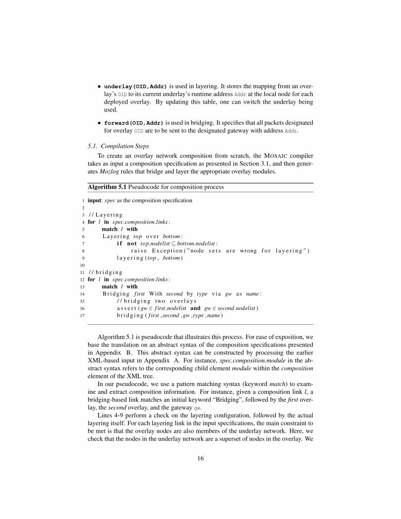
5.1. Compilation StepsTo create an overlay network composition from scratch, the MOSAIC compiler
takes as input a composition specification as presented in Section 3.1, and then gener-ates Mozlog rules that bridge and layer the appropriate overlay modules.
Algorithm 5.1 Pseudocode for composition process
1 input: spec as the composition specification2
3 / / L a y e r i n g4 for l in spec.composition.links :5 match l with6 L a y e r i n g top ove r bottom :7 i f not top.nodelist ⊆ bottom.nodelist :8 r a i s e E x c e p t i o n ( ” node s e t s a r e wrong f o r l a y e r i n g ” )9 l a y e r i n g ( top , bottom )
10
11 / / b r i d g i n g12 for l in spec.composition.links :13 match l with14 B r i d g i n g f irst With second by type v i a gw as name :15 / / b r i d g i n g two o v e r l a y s16 a s s e r t ( gw ∈ f irst.nodelist and gw ∈ second.nodelist )17 b r i d g i n g ( f irst ,second ,gw , type ,name )
Algorithm 5.1 is pseudocode that illustrates this process. For ease of exposition, webase the translation on an abstract syntax of the composition specifications presentedin Appendix B. This abstract syntax can be constructed by processing the earlierXML-based input in Appendix A. For instance, spec.composition.module in the ab-stract syntax refers to the corresponding child element module within the compositionelement of the XML tree.
In our pseudocode, we use a pattern matching syntax (keyword match) to exam-ine and extract composition information. For instance, given a composition link l, abridging-based link matches an initial keyword “Bridging”, followed by the first over-lay, the second overlay, and the gateway gw.
Lines 4-9 perform a check on the layering configuration, followed by the actuallayering itself. For each layering link in the input specifications, the main constraint tobe met is that the overlay nodes are also members of the underlay network. Here, wecheck that the nodes in the underlay network are a superset of nodes in the overlay. We
16

use the pattern matching syntax to extract the overlay as top and the underlay as bottomfor any links that involve layering. Line 9 performs the actual task of bridging afterconstraint checks are performed. This involves calling additional functions layering,shown as Algorithm 5.2 in Section 5.2.
Lines 11-16 check that all constraints are met for composition links that involvebridging multiple modules, followed by the actual bridging itself. If two modules arebridged via a gateway, this gateway node must belong to the node list of both modules.After the check is performed, the actual bridging is performed by invoking the bridging
function, shown as Algorithm 5.3 in Section 5.3.After the compilation, the rules are shipped to the corresponding physical nodes
for deployment. To modify an existing network composition, most of the proceduresremain the same except that the node membership sets of existing overlays are ob-tained by querying the directory service, and modified Mozlog rules are uploaded tothe physical nodes to implement the new composition.
5.2. Layering
Algorithm 5.2 Pseudocode for layering-related rule generation
1 function layering(top, bottom):2 input: overlay top, overlay bottom / / l a y e r top ove r bottom3 output: rules for layer bindings4 for n in top.nodelist :5 i f top.oid /∈ n.deployed : / / ne twork top i s n o t d e p l o y e d on node n6 code = f e t c h ( top.codeurl )7 addRule ( n , code )8 addRule ( n , "underlay(top.oid, Addr) :-9 netAddress(bottom.oid, Addr)." )
10 e l s e :11 u p d a t e R u l e ( n , "underlay(top.oid, Addr) :-12 netAddress(bottom.oid, Addr)" )
Layering of a control or data plane over another overlay’s data plane is achievedthrough the use of the underlay table describing bindings from each overlay node toits current runtime underlay address. Abstracting the bindings into a table provides asimple mechanism for switching overlays: MOSAIC can simply update the underlay
table — changing both the underlay protocol and node address accordingly.Given a composition specification with layering links, Mozlog rules are generated
to implement the layering. Algorithm 5.2 shows the pseudocode for rule generation.The function addRule(n,r) is used to add a rule r to the node n. If executed at thecomposition service, this means that all generated rules have to be shipped from theservice to be instantiated at each corresponding node.
If the overlay top is not deployed on the node n, we first add the overlay Mozlogimplementation to the code to be deployed on node n (Lines 6-7), then bind the addressof network bottom to the underlay table entry that belongs to network top (Line 8).Note that symbols in italic fonts, including n, top.oid, and bottom.oid are constants
17

when added into the rule. If top is deployed, then there should be a rule that binds itsunderlay table already. We update that rule to the new binding (Lines 11-12).
We illustrate using an example where there are two RON overlays, layered overIP and i3. Based on the specifications, at every node, there are two instances of RONexecuting ( ron oid1 and ron oid2), and one instance of i3 (i3 oid). The followingMozlog rules b1 and b2 are generated to build the two networks:
b1 underlay(ron_oid1, U) :- netAddress(0, U).b2 underlay(ron_oid2, U) :- netAddress(i3_oid, U).
Since ron oid1 utilizes IP for routing, rule b1 takes as input netAddress(@N,0,U),based on the executing node’s default IP address. On the other hand, ron oid2 routesover i3, hence its underlay tuple stores the address of the underlying i3 oid node re-trieved from the local netAddress table.
Note that the layering association is not static. A deployed, running overlay net-work can switch the underlying network from one to another by updating its underlaytable entries at runtime. This enables dynamic overlay composition. We will discussan example of dynamic switching in Section 6.
Next, the rule to update the netAddress table is generated for the newly createdoverlay. Because the rule is overlay specific, it is not automatically generated by thecompiler, but provided by the overlay programmers. For example, consider the i3and RON overlays with identifiers i3 oid and ron oid respectively. In i3, its overlayaddress is the SHA-1 hash of the node’s public key K (as shown in rule d1).
d1 netAddress(i3_oid, A) :- publicKey(K), A = i3_oid::f_sha1(K).
On the other hand, in RON, since its routable address is tightly coupled with itsunderlay, its address is its own underlay address (typically the IP address that RONuses) annotated with the overlay id as shown rule d2:
d2 netAddress(ron_oid, A) :- underlay(ron_oid,U), A = ron_oid::U.
Finally, data plane forwarding rules may also need to be slightly changed. We up-date the RON forwarding rules snd and rcv from Section 4.3 in the context of layering:
snd ron_oid.send@Next(Dest,Packet) :- ron_oid.send(Dest, Packet),ron_oid.RT(Dest, Next),underlay(ron_oid, Local),Local != Dest.
rcv ron_oid.recv(Packet) :- ron_oid.send(Dest, Packet),underlay(ron_oid, Local),Local = Dest.
The local address stored in localAddr is replaced by underlay(ron oid,Local),where Local is the current underlay address of the overlay ron oid. Note that whilethe above rules achieve the same functionality as the previous two rules in Section 4.3,they are more flexible in allowing packets to route over underlays that can be switchedat runtime.
18

Algorithm 5.3 Pseudocode for bridging-related rule generation
1 function bridging( f irst, second, bridgetype,gw, bn):2 input: overlay f irst, overlay second, gateway gw, bridge name bn3 output: bridging related rules4
5 gwAddr = d n s l o o k u p ( gw )6
7 for n in f irst.nodelist :8 i f n 6= gw :9 i f b r i d g e t y p e =” on−demand ” :
10 addRule ( n , "netAddress(bn, Addr) :-11 netAddress@gwAddr(second.oid, SecondGWAddr),12 netAddress( f irst.oid, FirstNodeAddr),13 Addr = sr::[SecondGWAddr, FirstNodeAddr].” )14 e l s e : / / pre−c o n f i g u r e d method15 addRule ( n , "forward(second.oid, FirstGWAddr) :-16 netAddress@gwAddr(first.oid, FirstGWAddr)." )17
18 for n in second.nodelist :19 i f n 6= gw :20 i f b r i d g e t y p e =” on−demand ” :21 addRule ( n , "netAddress(bn, Addr) :-22 netAddress@gwAddr( f irst.oid, FirstGWAddr),23 netAddress(second.oid, SecondNodeAddr),24 Addr=sr::[FirstGWAddr, SecondNodeAddr]." )25 e l s e : / / pre−c o n f i g u r e d method26 addRule ( n , "forward( f irst.oid, SecondGWAddr) :-27 netAddress@gwAddr(second.oid, SecondGWAddr)." )
19

5.3. BridgingAlgorithm 5.3 shows the pseudocode for bridging two overlays named first and
second via a gateway node gw. In the pseudocode, we assume that the gateway gw
is reachable by the Internet which serves as the management channel, hence its ad-dress gwAddr can be retrieved via DNS lookup on gw. Note that since gw participates inboth networks, it has two overlay nodes with addresses firstGWAddr and secondGWAddr,one for each participating overlay that it bridges. As a result, at node gw, it main-tains two netAddress entries for each one of its participating overlay node, i.e. entriesnetAddress(first.oid, firstGWAddr) and netAddress(second.oid, secondGWAddr).In addition, each node maintains a netAddress entry for the overlay it participates in.For instance, a node firstNodeAddr in the first overlay will include an entry netAddress(
first.oid, firstNodeAddr) in its local netAddress table.We focus on explaining the pseudocode from the perspective of the first overlay
(lines 7-16). The explanation for the second overlay is symmetrical. We first describethe Mozlog rule generated for the on-demand method (lines 9-13). Recall from Sec-tion 3.2.2 that in the on-demand method, source routing is used to create an explicit pathfrom a node in one network to another node in a bridged network, via an intermediategateway node. Our generated Mozlog rule (lines 10-13) distinguishes local predicatesat each node n from remote predicates at the gateway (indicated by @gwAddr).
Unlike the pre-configured case discussed below, since source routing is used, noexplicit forwarding state need be maintained. Instead, the main goal is to set up theappropriate netAddress entries for the new bridge such that source routes can be latercreated in order to route to nodes within the bridge networks. Mozlog supports a sourceroutable address type of the form sr::[gateway, dest], which explicitly describes thedata path to dest via an intermediate gateway node. All nodes will automatically han-dle the forwarding of such messages to the next recipient in the path as specified in thesource route. For instance, at overlay first, its netAddress table for the bridge bn main-tains a source address sr::[SecondGWAddr,FirstNodeAddr], which indicates that in or-der for a node in the second overlay to reach the node with address FirstNodeAddr inthe first overlay, the packet has to first traverse to the gateway node SecondGWAddr in thesecond overlay, before the packet can be sent to the destination node FirstNodeAddr.
In the pre-configured method (lines 14-16), the address of the gateway gw for over-lay oid is stored in a local forward table at each node. For instance, at the first over-lay, its local forward(second.oid, firstGWAddr) table indicates that in order to routeto the overlay second, the packet has to be first routed to gw node, specifically thefirstGWAddr overlay node on the gateway that is also participating in the first overlay.When the packet reaches firstGWAddr, it is then forwarded to the appropriate node inoverlay second based on the destination address stored in the packet. Unlike the earlieron-demand method, no source routing is required.
6. Composition Examples
MOSAIC can support flexible overlay compositions including bridging, layeringand hybrid compositions. We present two examples, one that revisits the mobile VoIPexample introduced in Section 1, and a second that illustrates dynamic composition.Appendix A gives an XML composition specification based on the first example.
20

overlay id addressalice net alice internal ip
br1 sr::[alice gateway ip, alice internal ip]br2 sr::[ron oid::alice gateway ip, alice internal ip]
i3 oid i3 oid::alice id
Table 1: netAddress table at Alice
overlay id address0 alice gateway ip
alice net alice gw internal ipron oid ron oid::alice gateway ip
Table 2: netAddress table at Alice’s gateway
6.1. VoIP between Alice and Bob
Consider the example of Section 1. An overlay composition can solve the problem.Suppose there is a publicly available i3 overlay network, and Alice uses her gatewaynode at home to form a private RON network with Bob and her other friends. Alice andBob agree on the composition specification shown in Figure 4. Based on the overlayspecification, MOSAIC generates the Mozlog rules to compose overlays together.
Because Alice’s situation mirrors Bob’s, we use Alice’s rules and network stateto explain the composition process. First, at Alice’s gateway, we configure the RONoverlay network over IP as:
c1 underlay(ron_oid,A) :- netAddress(0,A).
We then use bridging to create publicly reachable addresses br1 and br2 as shownin Table 1. br1 bridges the internal network AliceNet with the public IP network, andbr2 bridges AliceNet with the RON network.
Finally, we layer i3 over the bridged networks we created. Because Alice wants tohave reliability for VoIP, we choose the bridging overlay with br2 as i3’s underlay. Thecomposition rule deployed at the Alice node is as follows:
c2 underlay(i3_oid,A) :- netAddress(br2,A).
When Bob initiates a VoIP call to Alice, he first uses Alice’s i3 ID to look upher public trigger, and sends traffic to Alice via i3’s indirection path. After they havelocated each other, they switch to the i3 shortcut data path as the underlay networkspecifies, which is layered on top of RON and can traverse internal networks (e.g.,those behind NATs) using source routing along the gateways.
6.2. Dynamic Composition of Chord over IP and RON
To illustrate dynamic composition, we use the Chord DHT to show the benefit ofdynamically switching the underlying data path from IP to RON. In Chord, temporarynetwork failures may create non-transitive connectivity between the nodes, possibly
21

creating problems such as invisible nodes, routing loops and broken return paths [11].Instead of altering the DHT protocol, an alternative is to layer Chord over a resilientrouting protocol such as RON that eliminates non-transitivity. Layering Chord overRON can be viewed as trading scalability for performance.
Ch d
Chord
Chord
RON
switchUnderlay (ron_oid)
rule s1
IP
RON
IPswitchUnderlay(0)
rule s1rule s2
IPswitchUnderlay(0)
Figure 5: Dynamic composition of Chord over two different underlays (IP and RON).
The following rules define two types of layering: Chord over IP and Chord overRON (See Figure 5):
s1 underlay(chord_oid,A) :- netAddress(OID,A), switchUnderlay(OID).s2 underlay(ron_oid,A) :- netAddress(0,A).
In s1-s2, we added a switchUnderlay(OID) predicate to switch Chord’s underlayto that indicated by the OID variable. This switchUnderlay can itself be triggered by anevent sent from the administrator based on changes to the overlay specifications. Rules1 indicates that Chord uses IP as the underlying address when OID is 0, and RON whenOID is ron oid. Rule s2 defaults RON to use IP at all times. To switch between the twolayering schemes, one only needs to generate switchUnderlay accordingly.
Dynamic switching is useful because the trade-off between scalability and perfor-mance is at the discretion of the Chord administrators, who can make decisions basedon network conditions, requirements, etc. If a new overlay providing both resiliencyand scalability (e.g. SOSR [14]) becomes available, one can switch Chord’s underlayfrom RON to the new one to further improve scalability. Unlike restarting Chord fromscratch, dynamic switching preserves existing state in the network such as key/valuepairs without disrupting the DHT lookup service. Once the Chord underlay networkaddress is changed on a node, the stabilization process will propagate it to the node’ssuccessors, predecessor and other nodes that have it in its finger table. We present ourexperimental evaluation of this example in Section 8.3.
7. Implementation
The MOSAIC platform builds on the P2 [21] declarative networking system, addingsignificant new functionalities. The P2 planner and dataflow engine have been re-vised to generate execution plans that accommodate new language features of Mozlog:specifically, those related to runtime support for dynamic location specifier, data planeforwarding, and interactions with legacy applications.
22
MOSAIC takes a Mozlog program, compiles it into distributed P2 dataflows [21],and deploys it to all nodes that participate in the overlay. A single node may host mul-tiple overlay networks at the same time. P2 dataflows resemble the execution model ofthe Click modular router [18], which consists of elements that are connected togetherto implement a variety of network and flow control components. In addition, P2 ele-ments include database operators such as joins, aggregation, selections, and projectionsthat are directly generated from queries. Each local dataflow participates in a global,distributed dataflow across the network, with messages flowing among elements at dif-ferent nodes, resulting in updates to local tables. The local tables store the state ofintermediate and computed query results, including structures such as routing tables,the state of various network protocols, and data related to their resulting compositions.The distributed dataflows implement the operations of various network protocols. Theflow of messages entering and leaving the dataflow constitute the network packets gen-erated during query execution.
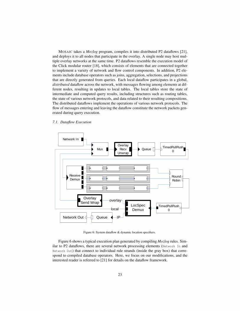
7.1. Dataflow Execution
Network In
Mux TimedPullPush 0Queue
OverlayRecv
Unwrap
ReceiveDemux
TimedPullPush0
RoundRobin
LocSpecDemux
OverlaySend Wrap
QueueNetwork Out IP
overlay
local
Figure 6: System dataflow & dynamic location specifiers.
Figure 6 shows a typical execution plan generated by compiling Mozlog rules. Sim-ilar to P2 dataflows, there are several network processing elements (Network In andNetwork Out) that connect to individual rule strands (inside the gray box) that corre-spond to compiled database operators. Here, we focus on our modifications, and theinterested reader is referred to [21] for details on the dataflow framework.
23

To implement dynamic location specifiers and overlay forwarding on the data plane,we modify the planner to automatically generate three additional MOSAIC elementsshown in bold in the dataflow: OverlayRecvUnwrap, OverlaySendWrap, and LocSpecDemux.The elements OverlayRecvUnwrap and OverlaySendWrap are used for de-encapsulationand encapsulation of tuples from overlay traffic.
At the top of the figure, the Mux multiplexes incoming tuples received locally orfrom the network. These tuples are processed by the OverlayRecvUnwrap element thatextracts the overlay payload for all tuples of the form overlay.recv(Packet), wherePacket is the payload with type tuple. Since the payload may be encapsulated bymultiple headers (for layered overlays), this element needs to be “unwrapped” untilthe payload is retrieved. The Packet payload is used as input to the dataflow via theReceiveDemux element, which itself is then used as input to various rule strands forexecution.
Executing the rule strands results in the generation of output tuples that are sent to aLocSpecDemux element. This element checks the runtime type of the location specifier,and then demultiplexes as follows:
• Tuples tuplename(F1, F2, ..., Fn) are local tuples and sent to the Mux.
• Tuples tuplename@IPAddr(F1, F2, ..., Fn) are treated as regular IP-based tu-ples and sent to the network directly.
• Tuples tuplename@oid::ovaddr(F1, F2, ..., Fn) are designated for overlay net-work oid with address ovaddr. A new event tuple oid.send(ovaddr, tuplename(F1,
F2, ..., Fn)) which denotes the send primitive of the overlay network oid
is generated (see Section 4.3). This new tuple is reinserted back to the samedataflow to be forwarded based on the overlay specification.
7.2. Legacy SupportWe use the tun device to provide overlay tunnels between legacy applications at
the network layer. The tun predicate is reserved for legacy support, and tuples using itare treated differently from ordinary tuples in the dataflow. Each special predicate hasa rule strand in the dataflow, between the ReceiveDemux element and the RoundRobin
element (see Figure 6). Two elements Tun::Tx and Tun::Rx are inserted in the tun rulestrand right after ReceiveDemux. Tun::Rx reads IP packets from the tun device, gener-ates the tun tuple, and sends to the next element in the rule strand; Tun::Tx receives atun tuple, formats it as an IP packet and writes to the tun device.
For each end host, it takes a private IP address from 1.0.0.0/8 to avoid conflicts withother public IP networks. After a legacy application sends a packet to an address in thetun network, the kernel redirects it to MOSAIC, where the Tun::Rx element generatesa tun tuple. Currently there is an address translation rule that uses a special mappingtable to translate the private IP address to the overlay address. This can be extendedin the future to use any name resolution service by combining DNS request hijack-ing [15]. After address translation, the packet tunneling rules such as the rule i3 tun ofSection 4.5 deliver the IP packet to the destination via the corresponding overlays. Af-ter the tun tuple is delivered to the remote node, it is redirected to the tun device by theelement Tun::Tx, and finally the tunneled packet is received by the legacy application.
24

To support a legacy overlay that is not implemented in MOSAIC, we build anadapter for the overlay to interact with MOSAIC via the send and recv primitives. Theadapter redirects the legacy.send tuple from the dataflow to the overlay, and injectsthe legacy.recv tuple upon overlay’s packet reception. Because the legacy overlaysare built on IP, they can only be bridged with other overlays or used as substrates un-derneath other networks, but cannot be layered on top of another overlay for either thecontrol or the data plane.
7.3. Compilation of CViews
The Mozlog-to-NDlog translator rewrites and expands all CView rules into NDlogrules, which can then be compiled into dataflow strands using the P2 planner. Thecompilation process involves a query rewrite that takes as input all CView predicates,and expands them into multiple NDlog rules based on their view definitions.
Since this process resembles function call compilation, we reuse the terms callerand callee. A rule that takes an input CView predicate is the caller. The set of rulesbased on the view definition (e.g., rules p1-p3 in Section 4.4) comprises the operationsof the callee.
In a typical C compiler, the caller maintains a stack, pushing local variables (exe-cution context) and the return address before a call. Similarly, for each CView inputpredicate viewName[@locSpec] (K1,...,Kn, &R1,...,&Rm), the execution context is allthe bound variables K1,...,Kn and the variables that appear in the rule body before theCView term. The expanded rules are executed, and the local variables are stored ina designated internal context table. This local state is stored for the duration of viewexecution. Each expanded set of rules replaces the this prefix in the original view defi-nition with a query context identifier CID that uniquely identifies the current invocationof the view, and a return address RetAddr of the caller. When the caller has finishedexecuting all the rules for the view, the results are returned to the caller (RetAddr).
We use the following ping CView presented in Section 4.4 to demonstrate theCView compilation process. The following rules show the compilation result fromthe ping module. All predicates within the CView are appended with two fields, CID asthe query context identifier and LVReturnAddr as the return address to the caller.
ping_p1 ping_pingReq(@RI,NI,T,CID,LVReturnAddr):-ping_init(@NI,RI,CID,LVReturnAddr), T = f_now().
ping_p2 ping_pingResp(@RI,T,CID,LVReturnAddr):-ping_pingReq(@NI,RI,T,CID,LVReturnAddr).
ping_p3 ping_return(@LVReturnAddr,Delay,CID):-ping_pingResp(@NI,T,CID,LVReturnAddr), Delay = f_now()- T.
Suppose the caller rule is
r1 pingResult(@NI,RI,Delay):- periodic(@NI,E,2),RI=DESTADDR, ping(@NI, RI, &Delay).
25

Rule r1 periodically measures the RTT to the destination node RI. The translationresult is showed as follows:
r1_cxt r1_ctxt(@NI,CID,E,RI) :- periodic(@NI,E,2),RI=DESTADDR,CID = f_rand().
r1_init ping_init( @NI,RI,CID,NI) :- r1_ctxt(@NI,CID,E,RI).r1_return pingResult(@NI,RI,Delay):- r1_ctxt(@NI,CID,E,RI),
ping_return(@NI,Delay,CID).
First, a table r1 ctxt is generated to store query identifiers and query context(bound variables before the CView term) locally. Second, rule r1 cxt generates aunique query identifier CID and saves the context variables (NI, E, RI). Then, ruler1 init invokes the ping CView, and finally rule r1 return takes the return tuplefrom the ping CView, which is joined with the saved context, and emits the resultpingResult.
8. Evaluation
In this section, we present the evaluation of MOSAIC on a local cluster and onPlanetLab. First, we validate that Mozlog specifications for declarative networks, com-positions, tunneling and packet forwarding are comparable in performance to nativeimplementations. Second, we use our implementation to demonstrate feasibility andfunctionality, using actual legacy applications that run unmodified on various com-posed overlays using MOSAIC. Third, we evaluate the dynamic composition capabili-ties of MOSAIC.
In all our experiments, we make use of a declarative Chord implementation whichconsists of 35 rules. Our i3 implementation uses this Chord and adds 16 further rules.We also implement the RON overlay in 11 rules. Both i3 and RON can be used bylegacy applications via the tun device, as described in Section 4.5.
8.1. LAN ExperimentsTo study the overhead of MOSAIC, we measured the latency and TCP throughput
between two overlay clients within the same LAN. The experiment setup was on alocal cluster with eight Pentium IV 2.8GHz PCs with 2GB RAM running Fedora Core6 with kernel version 2.6.20, which are interconnected by gigabit Ethernet. Whilethe local LAN setup and workload is not typical of MOSAIC’s usage, it allows us toeliminate wide-area dynamic artifacts that may affect the measurements. We measuredthe latency using ping and TCP throughput using iperf.
In the experiments, we use the tun device to provide legacy application support fornetwork layer overlays. MTU was reduced to 1250 bytes to avoid fragmentation whenheaders were added. The measurement results are shown in Table 3 for the followingtest configurations:DirectIP: Two nodes communicate via direct IP, where iperf can fully utilize thebandwidth of the Gigabit network. This serves as an indication of the best latency andthroughput achievable in our LAN.
26

test latency(ms) throughput (KByte/s)DirectIP 0.10 97994
OpenVPN 0.30 13951MozTun 0.50 8353
RON 0.71 5796i3 1.31 3299
Table 3: Overhead comparison in LAN
OpenVPN: OpenVPN [1] is a widely used tunneling software system. Using Open-VPN version 2.0.9, we set up a point-to-point tunnel via UDP between two clusternodes and disabled encryption and compression. The performance results provide abaseline for the overhead using the tun device virtualization. Compared to DirectIP,the latency increases by around 0.2ms, and the TCP throughput drops by a factor ofmore than 6. This overhead is inevitable for all overlay networks supporting legacyapplications using the tun device, including those hosted on MOSAIC.MozTun: We set up a static point-to-point tunnel in MOSAIC between two clusternodes. MozTun and OpenVPN essentially have the same functionality except thatMozTun is implemented in MOSAIC. The additional overheads in throughput and la-tency are solely from the MOSAIC dataflow processing overhead bounded by CPU ca-pacity. In MozTun, the latency increased 0.20ms over OpenVPN, which is negligiblewhen executed over wide-area networks.RON: We ran the RON network using MOSAIC and utilize two nodes to run the mea-surements. Since RON does not provide any benefit in our LAN setting as there areno failures, the comparison to MozTun is used to show the extra overhead for ruleprocessing in our implementation.i3: Six nodes were set up as i3 servers, using Chord to provide lookup functionality.The remaining two nodes were selected as i3 clients. A packet sent by the source i3client to the destination i3 client went through the public trigger of the destination,which was hosted on the i3 server of another cluster node. Since it introduced a levelof indirection plus extra rule processing overhead, i3 added the most cost among the 5configurations studied.
In summary, the overhead of MOSAIC is respectable: the throughput of MOSAIC’spoint-to-point tunneling (MozTun) is comparable to that obtained by using well-knowntunneling software (OpenVPN). In the extreme case (the additional level of indirectionof i3 with tunneling), the additional latency (1.2ms) incurred is negligible for an ap-plication running on wide-area networks. Later, in Section 8.2, we will validate theperformance of a composed overlay on the Planetlab testbed.
8.2. Wide-area Composition Evaluation
We deployed MOSAIC on PlanetLab to understand the wide-area performance ef-fects of using the system. We purposely chose a composed overlay including i3, RON,source routing, and tunneling for legacy applications (all implemented within MOSAICin 69Mozlog rules) to bring the Alice example from the introduction and Section 6.1 toa resolution.
27
Our experimental setup is as follows. As our end-host, we used a Linux PC inNew Jersey with a high speed cable modem connection (4Mbps downstream speed)as the gateway node, which performed NAT for a Thinkpad X31 laptop. The laptopfunctioned as our server, using Apache to serve a 21MB file. The file was downloadedfrom a machine in Utah with a modified version of wget that records the downloadthroughput.
These two nodes in New Jersey and Utah, plus three additional nodes (two on theEast Coast of the US, and one on the West Coast of the US), were used to form a privateRON network. We further selected 44 PlanetLab nodes, mostly in the US, to run i3.During the experiment, we validated the functionality of resilient routing provided byRON by manually injecting network failures via changing the firewall rules on thegateway to block the downloader’s traffic 30 seconds after wget was started; then weunblocked the traffic after another 30 seconds. For the purposes of comparison with thebest case scenario, we repeated the same test using direct IP communication. Note thatdirect IP loses all the benefits of our composed overlay (no resilience, NAT, or mobilitysupport), but achieves the best possible performance. Since our server was behind aNAT, in the direct IP experiment, we had to manually set up a TCP port forwardingrule on the gateway node to reach the Apache server. We repeated multiple runs of theexperiments and observed no significant differences.
Figure 7 shows the throughput of the download over time for MOSAIC and Di-rectIP. Network failures were injected 30 seconds after experiment start, and removedafter 30 additional seconds. We make the following observations. First, MOSAIC’sperformance over the wide area is respectable. Despite implementing the entire com-posed overlay (including legacy support for applications using MOSAIC) in Mozlog,we incurred only 20% additional overhead compared to using direct IP, while achiev-ing the benefits of mobility, NAT support and resilient routing. The majority of theoverhead comes from the extra packet headers for the composed overlay protocols—anoverhead that is repaid with significant functionality. Second, with respect to the func-tionality of our composed overlay, we were able to achieve successful downloads froma server behind a NAT using MOSAIC. In addition, resilient routing was achieved: theRON network periodically monitored the link status and recovered from routing fail-ures. Hence, during the period where we injected the routing failures, MOSAIC wasable to make a quick recovery from failure, as is shown by the sustained throughput.On the other hand, DirectIP suffered a failure (and hence a drop of throughput to zero)during the 30-60 second period. Overall, MOSAIC finished the download in a shortertime despite lower throughput, due to the resiliency of RON.
8.3. Dynamic Overlay Composition
In our final experiment, we evaluate the dynamic composition capabilities of MO-SAIC. Our setup consists of an 8-node cluster, where each node has a hardware config-uration similar to the setup in Section 8.1.
As a baseline prior to the dynamic switching experiment, we made static com-parisons between two composed networks: we executed Chord-over-IP and Chord-over-RON on our cluster, which consists of the Chord overlay on top of IP and RONrespectively. Our network size is 16, where each machine executed two instances of the
28
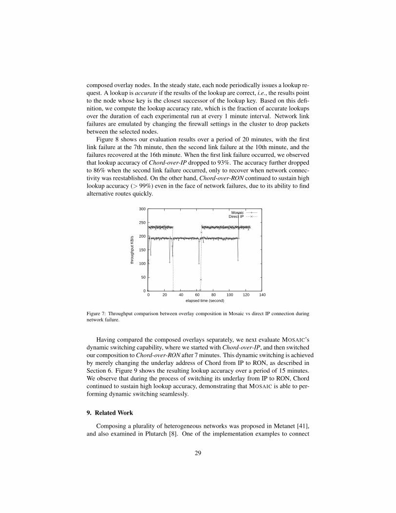
composed overlay nodes. In the steady state, each node periodically issues a lookup re-quest. A lookup is accurate if the results of the lookup are correct, i.e., the results pointto the node whose key is the closest successor of the lookup key. Based on this defi-nition, we compute the lookup accuracy rate, which is the fraction of accurate lookupsover the duration of each experimental run at every 1 minute interval. Network linkfailures are emulated by changing the firewall settings in the cluster to drop packetsbetween the selected nodes.
Figure 8 shows our evaluation results over a period of 20 minutes, with the firstlink failure at the 7th minute, then the second link failure at the 10th minute, and thefailures recovered at the 16th minute. When the first link failure occurred, we observedthat lookup accuracy of Chord-over-IP dropped to 93%. The accuracy further droppedto 86% when the second link failure occurred, only to recover when network connec-tivity was reestablished. On the other hand, Chord-over-RON continued to sustain highlookup accuracy (> 99%) even in the face of network failures, due to its ability to findalternative routes quickly.
0
50
100
150
200
250
300
0 20 40 60 80 100 120 140
thro
ughp
ut K
B/s
elapsed time (second)
MosaicDirect IP
Figure 7: Throughput comparison between overlay composition in Mosaic vs direct IP connection duringnetwork failure.
Having compared the composed overlays separately, we next evaluate MOSAIC’sdynamic switching capability, where we started with Chord-over-IP, and then switchedour composition to Chord-over-RON after 7 minutes. This dynamic switching is achievedby merely changing the underlay address of Chord from IP to RON, as described inSection 6. Figure 9 shows the resulting lookup accuracy over a period of 15 minutes.We observe that during the process of switching its underlay from IP to RON, Chordcontinued to sustain high lookup accuracy, demonstrating that MOSAIC is able to per-forming dynamic switching seamlessly.
9. Related Work
Composing a plurality of heterogeneous networks was proposed in Metanet [41],and also examined in Plutarch [8]. One of the implementation examples to connect
29

0 5 10 15 200
0.2
0.4
0.6
0.8
1lo
okup
acc
urac
y
time (minute)
chord over IPchord over RON
Figure 8: Lookup accuracy comparison betweenChord over IP and Chord over RON.
0 5 10 150
0.2
0.4
0.6
0.8
1
time (minute)
look
up a
ccur
acy
chord over IPchord over RON
Figure 9: Chord lookup performance during dy-namic underlay network switching from IP toRON.
multiple networks together is AVES [30]. Oasis [24] and OCALA [15] provide legacysupport for multiple overlays. Oasis picks the best single overlay for performance.OCALA proposes a mechanism to stitch (similar to MOSAIC’s bridge functionality)multiple overlay networks at designated gateway nodes to leverage functionalities fromdifferent overlays. Some projects focus on application level service composition, withdifferent emphases, such as adaptive configuration based on network conditions [12],fault tolerance and personalization [27] and performance and QoS awareness in P2Penvironments [13].
In contrast, MOSAIC’s primary focus is on overlay network specification and com-position within a single framework. As a result, MOSAIC is complementary to OCALAand Oasis. MOSAIC’s use of a declarative language results in more concise overlay net-work specification and composition, whose performance is quite comparable to nativecode. MOSAIC also provides support for layering in addition to bridging. Finally, MO-SAIC is not limited to IP-based networks, supports dynamic composition, and routingprimitives such as unicast and multicast. These benefits result in better extensibilityand evolvability of MOSAIC over existing composition systems.
Another class of composition work is Web service composition, as surveyed byMilanovic and Malek [28]. Each Web service serves like a remote procedure call overHTTP or HTTPS, and provides a relatively basic functionality, which is described withadditional pieces of information, either by a semantic annotation of what it does and/orby a functional annotation of how it behaves. The industry standard specification isWeb Service Definition Language (WSDL) [6]. A complicated application logic isbuilt by composing multiple Web services together, which is described separately ina flow specification, such as Business Process Execution Language for Web Services(BPEL4WS) [3]. The process of obtaining the composition flow is either manual or insome cases can be assisted by an AI planning software in the context of semantic Web.
Compared with network service composition, the major difference is that Web ser-vices are best described with request/response models, where usually only a singleentity is involved in utilizing a service (the service may still be provided by multi-ple providers). On the other hand, network services are based on send/receive models,where two (a sender and a receiver) or more (in the case of multicast/broadcast) entities
30
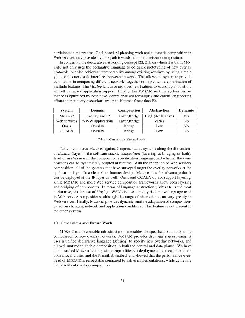
participate in the process. Goal-based AI planning work and automatic composition inWeb services may provide a viable path towards automatic network composition.
In contrast to the declarative networking concept [22, 21], on which it is built, MO-SAIC not only uses the declarative language to do quick prototyping of new overlayprotocols, but also achieves interoperability among existing overlays by using simpleyet flexible query-style interfaces between networks. This allows the system to provideautomation in composing different networks together to implement a combination ofmultiple features. The Mozlog language provides new features to support composition,as well as legacy application support. Finally, the MOSAIC runtime system perfor-mance is optimized by both novel compiler-based techniques and careful engineeringefforts so that query executions are up to 10 times faster than P2.
System Domain Composition Abstraction DynamicMOSAIC Overlay and IP Layer,Bridge High (declarative) Yes
Web services WWW applications Layer,Bridge Varies NoOasis Overlay Bridge Low No
OCALA Overlay Bridge Low No
Table 4: Comparison of related work.
Table 4 compares MOSAIC against 3 representative systems along the dimensionsof domain (layer in the software stack), composition (layering vs bridging or both),level of abstraction in the composition specification language, and whether the com-positions can be dynamically adapted at runtime. With the exception of Web servicescomposition, all of the systems that have surveyed target the overlay networks at theapplication layer. In a clean-slate Internet design, MOSAIC has the advantage that itcan be deployed at the IP layer as well. Oasis and OCALA do not support layering,while MOSAIC and most Web service composition frameworks allow both layeringand bridging of components. In terms of language abstractions, MOSAIC is the mostdeclarative, via the use of Mozlog. WSDL is also a highly declarative language usedin Web service compositions, although the range of abstractions can vary greatly inWeb services. Finally, MOSAIC provides dynamic runtime adaptation of compositionsbased on changing network and application conditions. This feature is not present inthe other systems.
10. Conclusions and Future Work
MOSAIC is an extensible infrastructure that enables the specification and dynamiccomposition of new overlay networks. MOSAIC provides declarative networking: ituses a unified declarative language (Mozlog) to specify new overlay networks, anda novel runtime to enable composition in both the control and data planes. We havedemonstrated MOSAIC’s composition capabilities via deployment and measurement onboth a local cluster and the PlanetLab testbed, and showed that the performance over-head of MOSAIC is respectable compared to native implementations, while achievingthe benefits of overlay composition.
31
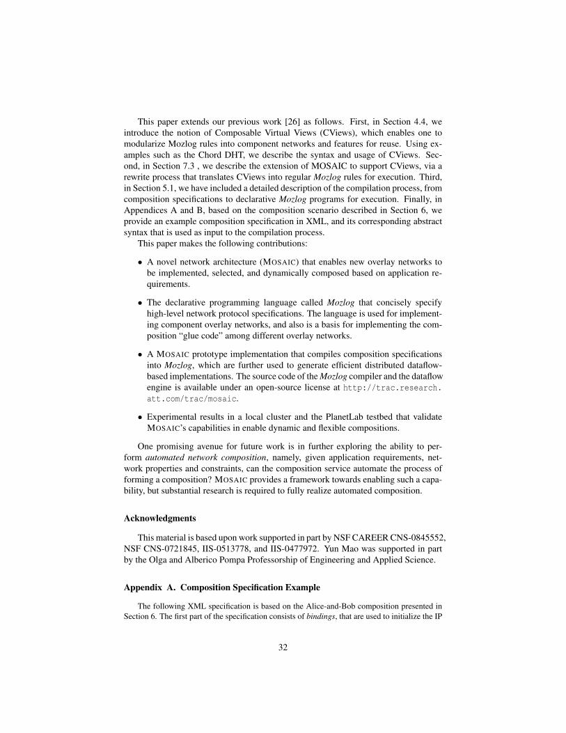
This paper extends our previous work [26] as follows. First, in Section 4.4, weintroduce the notion of Composable Virtual Views (CViews), which enables one tomodularize Mozlog rules into component networks and features for reuse. Using ex-amples such as the Chord DHT, we describe the syntax and usage of CViews. Sec-ond, in Section 7.3 , we describe the extension of MOSAIC to support CViews, via arewrite process that translates CViews into regular Mozlog rules for execution. Third,in Section 5.1, we have included a detailed description of the compilation process, fromcomposition specifications to declarative Mozlog programs for execution. Finally, inAppendices A and B, based on the composition scenario described in Section 6, weprovide an example composition specification in XML, and its corresponding abstractsyntax that is used as input to the compilation process.
This paper makes the following contributions:
• A novel network architecture (MOSAIC) that enables new overlay networks tobe implemented, selected, and dynamically composed based on application re-quirements.
• The declarative programming language called Mozlog that concisely specifyhigh-level network protocol specifications. The language is used for implement-ing component overlay networks, and also is a basis for implementing the com-position “glue code” among different overlay networks.
• A MOSAIC prototype implementation that compiles composition specificationsinto Mozlog, which are further used to generate efficient distributed dataflow-based implementations. The source code of the Mozlog compiler and the dataflowengine is available under an open-source license at http://trac.research.att.com/trac/mosaic.
• Experimental results in a local cluster and the PlanetLab testbed that validateMOSAIC’s capabilities in enable dynamic and flexible compositions.
One promising avenue for future work is in further exploring the ability to per-form automated network composition, namely, given application requirements, net-work properties and constraints, can the composition service automate the process offorming a composition? MOSAIC provides a framework towards enabling such a capa-bility, but substantial research is required to fully realize automated composition.
Acknowledgments
This material is based upon work supported in part by NSF CAREER CNS-0845552,NSF CNS-0721845, IIS-0513778, and IIS-0477972. Yun Mao was supported in partby the Olga and Alberico Pompa Professorship of Engineering and Applied Science.
Appendix A. Composition Specification Example
The following XML specification is based on the Alice-and-Bob composition presented inSection 6. The first part of the specification consists of bindings, that are used to initialize the IP
32

addresses of various subnets (AliceSubNet and BobSubNet), and regular hosts that serve eitheras gateway nodes (AliceBW and BobGW) or regular host (AlicePC).
These bindings are then used as a basis for creating new or using existing modules. Thesemodules essentially represent overlay networks components. For instance, the specificationsbelow creates a new module for AliceNet and BobNet, and adds gateway nodes AliceGW andBobGW to an existing RON overlay identified by ron oid. The RON overlay also includes aURL to a known location storing the implementation code for the overlay.
Finally, these modules are connected together via link specifications which compose mod-ules either by layering or bridging. In this example, AliceNet and RON are bridged together viathe AliceGW gateway, while BobNet and RON are bridged via the BobGW gateway. In addition,the i3 overlay is layered over RON, which itself is layered over IP (default with 0 as identifier).
<mosaic><bindings><subnet><name>AliceSubNet</name><ip>10.1.1.0</ip><mask>255.255.255.0</mask>
</subnet><subnet><name>BobSubNet</name><ip>10.2.1.0</ip><mask>255.255.255.0</mask>
</subnet><node><name>AliceGW</name><ip id="AliceSubNet">10.1.1.1</ip><ip id="0">123.45.67.8</ip>
</node><node> <name>AlicePC</name><ip id="AliceSubNet">10.1.1.12</ip>
</node><node><name>BobGW</name><ip id="0">234.56.78.1</ip>
</node></bindings><composition><module oid="AliceNet" Name="IP" type="Existing" /><module oid="BobNet" Name="IP" type="Existing" /><module oid="ron_1" name="RON" type="Extend"><nodelist><node>AliceGW</node><node>BobGW</node>
</nodelist><codeurl>http://www.mosaic-system.net/ron/v1</codeurl>
</module><module oid="i3_1" name="i3" type="Extend"><nodelist><node>AliceGW</node><node>BobGW</node>
</nodelist><codeurl>http://www.mosaic-system.net/i3/v1</codeurl>
</module>
<link type="bridge" name="AliceBridge"><first>AliceNet</first><second>ron_1</second>
33
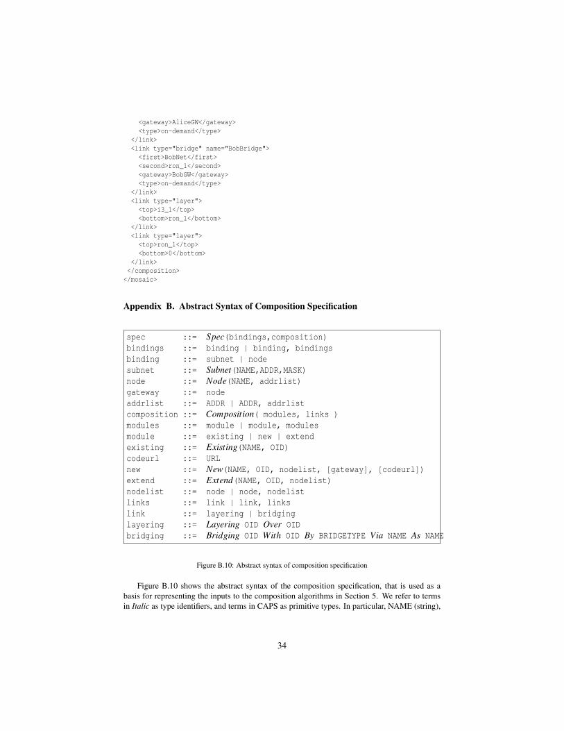
<gateway>AliceGW</gateway><type>on-demand</type>
</link><link type="bridge" name="BobBridge"><first>BobNet</first><second>ron_1</second><gateway>BobGW</gateway><type>on-demand</type>
</link><link type="layer"><top>i3_1</top><bottom>ron_1</bottom>
</link><link type="layer"><top>ron_1</top><bottom>0</bottom>
</link></composition>
</mosaic>
Appendix B. Abstract Syntax of Composition Specification
spec ::= Spec(bindings,composition)bindings ::= binding | binding, bindingsbinding ::= subnet | nodesubnet ::= Subnet(NAME,ADDR,MASK)node ::= Node(NAME, addrlist)gateway ::= nodeaddrlist ::= ADDR | ADDR, addrlistcomposition ::= Composition( modules, links )modules ::= module | module, modulesmodule ::= existing | new | extendexisting ::= Existing(NAME, OID)codeurl ::= URLnew ::= New(NAME, OID, nodelist, [gateway], [codeurl])extend ::= Extend(NAME, OID, nodelist)nodelist ::= node | node, nodelistlinks ::= link | link, linkslink ::= layering | bridginglayering ::= Layering OID Over OIDbridging ::= Bridging OID With OID By BRIDGETYPE Via NAME As NAME
Figure B.10: Abstract syntax of composition specification
Figure B.10 shows the abstract syntax of the composition specification, that is used as abasis for representing the inputs to the composition algorithms in Section 5. We refer to termsin Italic as type identifiers, and terms in CAPS as primitive types. In particular, NAME (string),
34
ADDR (network address), OID (overlay ID), MASK (network mask), BRIDGETYPE (either“on-demand” or “pre-defined” as two ways of bridging) and URL are primitive types.
The specifications are divided into bindings and composition. Bindings are used for initial-izing the name and address of each participating host in the composition. They can also refer toa group of nodes (subset). Each node is identified by its label (NAME) and IP address (ADDR),whereas each subnet additionally includes a network mask (MASK).
A composition is comprised of modules (i.e. component overlay) and links that composeoverlays together. Each module specification can either refer to an existing overlay component(Existing), extend an existing component by adding more nodes (Extend), or be created entirelyfrom scratch (New). When a new overlay component is created, it is initialized with the name ofa component (NAME), a unique identifier (OID), a list of nodes participating in the component(nodelist), an optional default gateway (node), and an optional URL that references the codethat implements the component. Each link specification refers to either layering, or bridging.Here, the layering specification layers one module over another, while the bridging specificationbridges one module with another via a specified gateway node.
References
[1] OpenVPN: Building and Integrating Virtual Private Networks.http://www.openvpn.net.
[2] David Andersen, Hari Balakrishnan, M. Frans Kaashoek, and Robert Morris. Re-silient Overlay Networks. In Proceedings of ACM Symposium on Operating Sys-tems Principles (SOSP), 2001.
[3] Tony Andrews, Francisco Curbera, Hitesh Dholakia, Yaron Goland,Johannes Klein, Frank Leymann, Kevin Liu, Dieter Roller, DougSmith, Satish Thatte, Ivana Trickovic, and Sanjiva Weerawarana.Business Process Execution Language for Web Services. 2003.http://www.ibm.com/developerworks/library/specification/ws-bpel/.
[4] Hari Balakrishnan, M. Frans Kaashoek, David Karger, Robert Morris, and IonStoica. Looking Up Data in P2P Systems. Communications of the ACM, Vol. 46,No. 2, February 2003.
[5] Hari Balakrishnan, Karthik Lakshminarayanan, Sylvia Ratnasamy, Scott Shenker,Ion Stoica, and Michael Walfish. A Layered Naming Architecture for the Inter-net. In Proceedings of the ACM SIGCOMM Conference on Data Communication,2004.
[6] Erik Christensen, Francisco Curbera, Greg Meredith, and Sanjiva Weer-awarana. Web Services Description Language (WSDL) 1.1. 2001.http://www.w3.org/TR/wsdl.
[7] D. Clark, C. Partridge, J. C. Ramming, and J. Wroclawski. A Knowledge Planefor the Internet. In Proceedings ACM SIGCOMM Conference, Karlsruhe, Ger-many, August 2003.
35

[8] J. Crowcroft, S. Hand, R. Mortier, T. Roscoe, and A. Warfield. Plutarch: AnArgument for Network Pluralism. In Proceedings of ACM SIGCOMM Workshopon Future Directions in Network Architecture (FDNA), 2003.
[9] John R. Douceur and Jon Howell. Distributed directory service in the farsite filesystem. In Proceedings of the 7th symposium on Operating Systems Design andImplementation (OSDI’06), pages 321–334, Seattle, Washington, 2006.
[10] M. Freedman, K. Lakshminarayanan, and D. Mazieres. OASIS: Anycast for anyservice. In Proceedings of the 3rd Symposium on Networked Systems Design andImplementation (NSDI’06), 2006.
[11] Michael J. Freedman, Karthik Lakshminarayanan, Sean Rhea, and Ion Stoica.Non-Transitive Connectivity and DHTs. In Proceedings of the Second Workshopon Real, Large Distributed Systems (WORLD’05), 2005.
[12] Xiaodong Fu, Weisong Shi, Anatoly Akkerman, and Vijay Karamcheti. Cans:Composable, adaptive network services infrastructure. In Proceedings of the 3rdUSENIX Symposium on Internet Technologies and Systems (USITS’01), 2001.
[13] Xiaohui Gu, Klara Nahrstedt, and Bin Yu. Spidernet: An integrated peer-to-peerservice composition framework. In Proceedings of the 13th International Sympo-sium on High-Performance Distributed Computing (HPDC-13), pages 110–119,Honolulu, Hawaii, June 2004.
[14] Krishna P. Gummadi, Harsha Madhyastha, Steven D. Gribble, Henry M. Levy,, and David J. Wetherall. Improving the reliability of internet paths with one-hop source routing. In Proceedings of the 6th Symposium on Operating SystemsDesign and Implementation (OSDI’04), 2004.
[15] Dilip Joseph, Jayanthkumar Kannan, Ayumu Kubota, Karthik Lakshmi-narayanan, Ion Stoica, and Klaus Wehrle. OCALA: An architecture for sup-porting legacy applications over overlays. In Proceedings of the 3rd Symposiumon Networked Systems Design and Implementation (NSDI’06), 2006.
[16] Dina Katabi and John Wroclawski. A framework for scalable global IP-anycast(GIA). In Proceedings of the ACM SIGCOMM Conference on Data Communica-tion, 2000.
[17] A. Keromytis, V. Misra, and D. Rubenstein. SOS: Secure overlay services. InProceedings of the ACM SIGCOMM Conference on Data Communication, 2002.
[18] Eddie Kohler, Robert Morris, Benjie Chen, John Jannotti, and M. FransKaashoek. The Click Modular Router. ACM Transactions on Computer Systems,18(3):263–297, 2000.
[19] Boon Thau Loo. The Design and Implementation of Declarative Networks (Ph.D.Dissertation). Technical Report UCB/EECS-2006-177, University of Californiaat Berkeley, 2006.
36

[20] Boon Thau Loo, Tyson Condie, Minos Garofalakis, David E. Gay, Joseph M.Hellerstein, Petros Maniatis, Raghu Ramakrishnan, Timothy Roscoe, and IonStoica. Declarative Networking: Language, Execution and Optimization. In Pro-ceedings of ACM SIGMOD International Conference on Management of Data,June 2006.
[21] Boon Thau Loo, Tyson Condie, Joseph M. Hellerstein, Petros Maniatis, TimothyRoscoe, and Ion Stoica. Implementing Declarative Overlays. In Proceedings ofACM Symposium on Operating Systems Principles (SOSP), 2005.
[22] Boon Thau Loo, Joseph M. Hellerstein, Ion Stoica, and Raghu Ramakrishnan.Declarative Routing: Extensible Routing with Declarative Queries. In Proceed-ings of the ACM SIGCOMM Conference on Data Communication, Philadelphia,PA, 2005.
[23] Harsha V. Madhyastha, Tomas Isdal, Michael Piatek, Colin Dixon, Thomas An-derson, Arvind Krishnamurthy, and Arun Venkataramani. iplane: An informationplane for distributed services. In Proceedings of the 7th symposium on OperatingSystems Design and Implementation (OSDI’06), Nov 2006.
[24] Harsha V. Madhyastha, Arun Venkataramani, Arvind Krishnamurthy, andThomas Anderson. Oasis: An Overlay-Aware Network Stack. In OperatingSystems Review, pages 41–48, 2006.
[25] Yun Mao, Bjorn Knutsson, Honghui Lu, and Jonathan M. Smith. DHARMA:Distributed Home Agent for Robust Mobile Access. In Proceedings of AnnualJoint Conference of the IEEE Computer Communications Societies (INFOCOM),2005.
[26] Yun Mao, Boon Thau Loo, Zachary G. Ives, and Jonathan M. Smith. MOSAIC:Unified Declarative Platform for Dynamic Overlay Composition. In Proceedingsof the 4th ACM International Conference on emerging Networking EXperimentsand Technologies (CoNEXT), 2008.
[27] Z. Morley Mao and Randy H. Katz. Achieving service portability using self-adaptive data paths. In IEEE Communications Magazine special Issue on ServicePortability and Virtual Home Environment, Jan 2002.
[28] N. Milanovic and M. Malek. Current solutions for web service composition.IEEE Internet Computing, 8(6):51–59, Nov 2004.
[29] Akihiro Nakao, Larry Peterson, and Andy Bavier. A Routing Underlay for Over-lay Networks. In Proceedings of the ACM SIGCOMM Conference on Data Com-munication, 2003.
[30] T. S. Eugene Ng, Ion Stoica, and Hui Zhang. A waypoint service approach toconnect heterogeneous internet address spaces. In Proceedings of the USENIXAnnual Technical Conference (USENIX’01), Boston, MA, June 2001.
37

[31] Larry Peterson, Scott Shenker, and Jon Turner. Overcoming the Internet ImpasseThrough Virtualization. In Proceedings of ACM HotNets-III, 2004.
[32] PlanetLab. Global testbed. 2002. http://www.planet-lab.org/.
[33] Anand Rajaraman, Yehoshua Sagiv, and Jeffrey D. Ullman. Answering queriesusing templates with binding patterns. In ACM Symposium on Principles ofDatabase Systems (PODS), 1995.
[34] Raghu Ramakrishnan and Jeffrey D. Ullman. A Survey of Research on DeductiveDatabase Systems. Journal of Logic Programming, 23(2):125–149, 1993.
[35] Sean Rhea, Brighten Godfrey, Brad Karp, John Kubiatowicz, Sylvia Ratnasamy,Scott Shenker, Ion Stoica, and Harlan Yu. Opendht: a public dht service and itsuses. In Proceedings of the ACM SIGCOMM Conference on Data Communica-tion, 2005.
[36] Skype. Skype P2P Telephony. 2006. http://www.skype.com.
[37] Jonathan Smith. Application-private networks. In David Gries, Fred B. Schnei-der, Andrew Herbert, and Karen Sparck Jones, editors, Computer Systems, Mono-graphs in Computer Science, pages 273–277. Springer New York, 2004.
[38] Ion Stoica, Daniel Adkins, Shelley Zhuang, Scott Shenker, and Sonesh Surana.Internet Indirection Infrastructure. In Proceedings of the ACM SIGCOMM Con-ference on Data Communication, 2002.
[39] Lakshminarayanan Subramanian, Ion Stoica, Hari Balakrishnan, and Randy Katz.OverQoS: An Overlay Based Architecture for Enhancing Internet QoS. In Pro-ceedings of the 1st Symposium on Networked Systems Design and Implementation(NSDI’04), 2004.
[40] Amin Vahdat and David Becker. Epidemic routing for partially-connected ad hocnetworks. Duke Technical Report CS-2000-06, 2000.
[41] J. T. Wroclawski. The Metanet. In Proceedings of Workshop on Research Direc-tions for the Next Generation Internet, 1997.
[42] Shelley Q. Zhuang, Kevin Lai, Ion Stoica, Randy H. Katz, and Scott Shenker.Host Mobility using an Internet Indirection Infrastructure. In Proceedings ofACM/Usenix Mobisys, 2003.
38