Mortise and Tenon Routing Procedures - Leigh jigs FMT User Guide Ch4.pdfBridle Joints Asymmetric...
28
SUPER FMT CHAPTER 4 Mortise and Tenon Routing Procedures 17 This chapter shows how to rout all types of mortise and tenon joints and how to adjust the joint fit. We will also show you some more efficient production methods. Before using your Leigh Super FMT you must have completed all of the preparatory steps including reading the router safety recommendations on the previous pages. If you haven’t done so, it is essential that you do it now. Single Mortise & Tenon, Test Production Procedures Small Joints Double Joints Twin Joints Quadruple Joints Triple Joints Different Workpiece Thicknesses Longer/Shorter Joints, Thicker/Wider Boards Angled Joints Through Tenons Bridle Joints Asymmetric Tenons Haunched Joints Doweling 4-1 Let’s make a plain single mortise and tenon. Using a fine pencil, mark a cross at the center of the required tenon and mortise posi- tions, the cross lines along and across the axis lines of the joint, at 90˚ to each other. Mark the mortise several inches[10cm] or so away from the end. 90˚ 4-2 In almost all cases, it is critical to have the same side of workpieces reference against the clamp plate for each tenon and mortise. So mark one side of each workpiece to reference “this side toward the clamp plate” ➀ , or “away from” if you prefer. Make a pencil mark ➁ to the required shoulder depth on the tenon workpiece. When the joint is cut, the tenon piece is rotated 180˚ to assemble ➂ . 1 2 1 3 Single Mortise and Tenon, Test 1 m IMPORTANT SAFETY NOTE Take great care to not “trap” the bit against the side of tenon rails ➀ . Do not attempt to rout center tenons in rails thicker than 1 5 / 16"[34mm] before referring to 4-77 thru 4-82. Without using the table movement as prescribed, the bit would have to be plunged into the side of the tenon rail causing the bit to powerfully “drive” the router across the jig. This could be dangerous and can damage the jig.
Transcript of Mortise and Tenon Routing Procedures - Leigh jigs FMT User Guide Ch4.pdfBridle Joints Asymmetric...

MORTISE AND TENON ROUTING PROCEDURESSuper FMT Frame Mortise & Tenon Jig User Guide
super fmt CHAPTER 4
Mortise and TenonRouting Procedures
17
This chapter shows how to rout all types of mortise and tenon joints and how to adjust the joint fit. We will also show you some more efficient production methods.
Before using your Leigh super fmt you must have completed all of the preparatory steps including reading the router safety recommendations on the previous pages. If you haven’t done so, it is essential that you do it now.
Single Mortise & Tenon, Test
Production Procedures
Small Joints
Double Joints
Twin Joints
Quadruple Joints
Triple Joints
Different Workpiece Thicknesses
Longer/Shorter Joints, Thicker/Wider Boards
Angled Joints
Through Tenons
Bridle Joints
Asymmetric Tenons
Haunched Joints
Doweling
4-1 Let’s make a plain single mortise and tenon. Using a fine pencil, mark a cross at the center of the required tenon and mortise posi-tions, the cross lines along and across the axis lines of the joint, at 90˚ to each other. Mark the mortise several inches[10cm] or so away from the end.
90˚
4-2 In almost all cases, it is critical to have the same side of workpieces reference against the clamp plate for each tenon and mortise. So mark one side of each workpiece to reference “this side toward the clamp plate” ➀, or “away from” if you prefer. Make a pencil mark ➁ to the required shoulder depth on the tenon workpiece. When the joint is cut, the tenon piece is rotated 180˚ to assemble ➂.
1
2
1
3
Single Mortise and Tenon, Test
1
m I M P O R TA N T S A F E T Y N O T ETake great care to not “trap” the bit against the side of tenon rails ➀. Do not attempt to rout center tenons in rails thicker than 15/16"[34mm] before referring to 4-77 thru 4-82.
Without using the table movement as prescribed, the bit would have to be plunged into the side of the tenon rail causing the bit to powerfully “drive” the router across the jig. This could be dangerous and can damage the jig.

18 Chapter 4 MORTISE AND TENON ROUTING PROCEDURESSuper FMT Frame Mortise & Tenon Jig User Guide
4-3 If you have not yet mounted the sidestop fence, do so now (see 3-7). Place it off center either side, it doesn’t matter which. Fit the table sight in the bit opening ➀. Loosen the table knobs ➁ and move the table to position the sight over the approximate tenon piece position ➂. Lock the table knobs. Always lock the table before positioning workpieces.
2
2
1
3
4-4 Clamp the tenon piece with the end lightly touching the underside of the sight ➀. Its side edge should touch the previously set sidestop fence ➁, with the marked side toward the clamp plate.
1
2
4-5 Loosen the table knobs and move the table until the sight opening is positioned equally around the layout marks on the workpiece. Lock the table. Because the human eye excels at comparisons, differences as small as .004 can be perceived in the space between the edges of the line and the triangles as shown here ➀. You can readily center the sight using slight table movements until the spaces appear the same ➁.
21
4-6 Unlock the two FB front/back limit stops. Move both so they touch the Stop Post, and tighten both stops ➀. This prevents front-to-back movement of the table when later sighting the mor-tise. Remove the sight and store it at the end of the jig.
1
4-7 Unplug the router. Insert the selected guide into the guide recess and matching diameter bit into to the router.
4-8 Make sure the two guide pins are turned up approximately two-and-a-half turns from the lowest position to avoid the end of the guide pin contacting the bottom of the guide pin track and guide recess! Place the router on the jig table, the right-hand guide pin in the right side track, the left-hand guide pin in the near side of the guide recess.

19Chapter 4MORTISE AND TENON ROUTING PROCEDURES Super FMT Frame Mortise & Tenon Jig User Guide
4-9 Adjust the right hand guide pin. Turn guide pin lock nut ➀ up under the guide pin ➁. Turn the guide pin down ➂ until all front to back "play" is eliminated ➃ then turn the guide pin up 1⁄8 of a turn ➄. To prevent the guide pin from turning, turn guide pin lock nut down firmly against the threaded boss. The router/sub-base should slide freely left to right. Once set, RH guide pin should require no more adjustment.
4 52
3
1
4-10 Repeat this procedure with the left hand guide pin set in a guide mortise slot. When you have set the guide pin with minimal ‘free play’, use a permanent ink pen to mark a small ‘dash’ at the 12 O’clock position on the guide pin ➁. Now all guide pin settings for joint fit with different guides and bits can be recorded as “number of turns up”, e.g. 11⁄8 up, 13⁄4 up, or possibly 1⁄8 down, etc. Each 1⁄8 turn of the LH pin changes the joint glue line fit by approximately 0.0011" [0.03mm].
24
4-11 Plunge the router so the tip of the bit is level with the pen-cil mark of the tenon shoulder ➀, and lock the plunge. Set the plunge depth stop rod to its stop. Tenons are routed in one depth setting; it is not necessary to make multiple passes at different depths of cut.
1
4-12 Read all of the next three instructions before routing. With guide pin in near side of guide recess, switch on router power and with firm control, move it in until the bit lightly touches the tenon workpiece. Very carefully, with the bit very lightly engaging the wood surface, “climb rout” clockwise around the tenon piece ➀. Maintain very light bit contact. Do not run guide pin on guide yet ➁.
21
4-13 Control the router firmly, the router is driven clockwise by the bit rotation. This first shallow climb cut will leave a small but clean shoulder ➀.
1
4-14 Routing counterclockwise, run the guide pin around the tenon guide surface. Make sure the pin contacts the entire outer surface ➀. In these first test cuts, check the tenon for a completely smooth cut before removing the piece from the jig. Until you are confident with this procedure, as a final cleanup we recommend you run the guide pin “off” of each guide “corner” ➁ in both directions ➂.
3
2
31

20 Chapter 4 MORTISE AND TENON ROUTING PROCEDURESSuper FMT Frame Mortise & Tenon Jig User Guide
4-15 Remove the router and tenon workpiece from the jig. Position the two clamps so the mortise piece can be positioned for secure holding. Clamp to either both sides of the bit opening ➀ or to one side ➁.Note: Leaving a “horn” on the ends of mortise pieces as in ➀ not only makes for easy clamping, the horns will be an aid in assembly gluing and clamping later.
1
2
4-16 Fit the sight and remove the sidestop fence if it is in the way. With the marked side of the mortise piece toward the clamp plate, either move the board left and right to align the cross with the sight and clamp in place, or clamp in place first and move the table to align the sight. Remember, you previously set the FB limit stops to allow only left/right movement.
4-17 Remove the sight and place the router/sub-base assembly on the jig, the left hand guide pin in the mortise slot part of the guide. Now raise the plunge stop rod ➀ slightly, say 1⁄32-1⁄16"[1-1,5mm] to allow the mortise to be routed slightly deeper than the tenon to ensure perfect tenon shoulder flushness on the finished joint.
1
4-18 The best way to rout mortises (parallel to workpiece) is to plunge slightly overlapping holes to full depth ➀, and then clean out left-right-left at full depth of cut ➁. Do not rout left-right-left at progressively greater depths without plunging holes ➂…the bit’s rotation will pull the bit off the intended mortise line with each pass ➃ and the mortise may not be parallel to the workpiece.
1
4
2
3
4-19 Make sure the guide pin is run clockwise against both the front and rear of the mortise guide slot on the final passes. The gap between pin and mortise guide slot is greatly exaggerated in this illustration.
4-20 Remove the mortise piece and keeping the marked faces adjacent, test the tenon for fit and flushness. If the face sides are not flush, check the straightness of the two parts. If they are straight, the clamp plate may not be vertically parallel to the bit. See Appendix II, Jig Adjustments, A2-1 through A2-3

21Chapter 4MORTISE AND TENON ROUTING PROCEDURES Super FMT Frame Mortise & Tenon Jig User Guide
4-21 Joint fit is adjusted with the left hand guide pin only. If the joint is too loose, turn the guide pin down ➀. If the joint is too tight, turn the guide pin up ➁. For how much, see 4-22. Guide pin changes affect the mortise and tenon, so rout a complete new joint. Establish ideal pin height for both mortise and tenon at one pin setting.
1 2
4-22 How much adjustment is required? 1⁄8 of a turn of the guide pin knob will change the joint glue-line fit by 0.001"[0,025mm] ➀, i.e. turn 1⁄ 8 up; the bit will reduce the tenon thickness by ~0.001"[0,025mm] (half of that per side ➁) and increase the mortise width by the same amount ➂. Dimensions and angles shown here are exaggerated.
11
2
3
4-23 The Super FMT can provide this accuracy for settings but remember, you’re working with wood and a hand-held router, with a lot of movement tolerances; it’s not a computer-controlled milling machine. Nevertheless, the Super FMT will allow you to do very precise and consistent work.
4-24 If you have a dial or digital calliper (every shop should have one) you can literally measure the tenon and mortise and adjust accordingly. Every ~0.002"[0,05mm] of difference in mortise to tenon size (say ~.001"[.025mm] on the glue line) should require 1⁄8 of a turn; down to tighten, up to loosen.
4-25 Generally we have found the best fit differential to be 0.005"[0,13mm] “loose”. Basically, the dry joint should “push” together fairly easily, but not fall apart under its own weight. If a mallet is needed, it’s too tight.
1
4-26 Once you’ve established the guide pin setting for a specific bit/guide combination, record the setting on the following page.For example: 5⁄16"x11⁄2"[8x35mm] “up 13⁄4 turns”. Using the same bit and guide next time, use the recorded setting for a good fit first time. Note: Different wood species may require slightly different settings. ■

22 Chapter 4 Frame Mortise & Tenon Jig User Guide MORTISE AND TENON ROUTING PROCEDURES
Leigh FMT Settings Record
TURNS UP SPECIES DATE
e.g. 1/2 x 2 1/2 1 -7/8 cherry 2/15/09e.g. 10 x40mm 10mm 1 -3/8 mahogany feb 20/09
TURNS UP SPECIES DATE
Hint: Photocopy or scan this page for future records.

23Chapter 4MORTISE AND TENON ROUTING PROCEDURES Super FMT Frame Mortise & Tenon Jig User Guide
4-27 When routing frame joints it is only necessary to mark and sight a single tenon and perhaps two mortises. Once the sidestop fence or outriggers are set and the table sighted for one joint, any number of similar joints may be routed without marking. We rec-ommend marking the finished face which goes against the clamp plate (shown here from operator view) ➀.
1
1
4-28 Mortises Sight ➀ one mortise and set a stop block ➁.
2
1
4-29 Set both sets of axis stops to prevent unintentional table movement ➀.
1
4-30 Sight the second mortise by moving the mortise piece (not the table), and set the second stop block ➀. Rout any number of successive (unmarked) mortises without removing the router from the table.
1
4-31 Multiple mortises in “ladder” type construction are rapidly routed. Mark all mortises on only one piece (only one of the marks needs a front-to-back mark!). Sight the first mortise (cross) to set the table and mark the top of one outrigger in line with workpiece end ➀. Table locked, move workpiece, sighting each successive mortise line, marking the outrigger(s) ➁. To rout, align unmarked board ends with outrigger marks ➁. ■
1
1
1
2
2
Production Procedures
24 Chapter 4 MORTISE AND TENON ROUTING PROCEDURESSuper FMT Frame Mortise & Tenon Jig User Guide
4-32 The Super FMT is designed so that both mortise and tenon of a particular sized joint may be routed with the same sized bit. So if you are making a single frame with a 1⁄4"[6mm] guide and bit, this works very effectively. However, if you are in production, it is much more efficient to rout small tenons with a larger bit.
Small Joints
4-33 For example, if you want to rout many 1⁄4"[6mm] mortises and tenons, the tenons can be much more speedily routed with a 1⁄2"[10mm] bit. Here’s how.Select 1⁄4"[6mm] bit for mortises ➀.Select 1⁄2"[10mm] bit for tenons ➁.Select 3⁄8"[8mm] guide ➂ for length from the guide/bit selection chart in Appendix I.
1
2
3
4-34 The diagram illustrates routing the 1⁄4" joint described above (guide not shown). The result is a perfect 1⁄4" mortise and tenon, 1⁄8" smaller both ways than the guide size. Any two bit diameters which add up to two times the nominal guide size will produce a joint the size of the smaller bit. Bear in mind, the maximum usable bit diameter with the Super FMT is 1⁄2"[12mm].
No
rmal
join
t
wit
h 3
/8"
bit
Smaller = 7/8"
Normal = 1"
1/4"
1/2"
3/4"
3/8"
3/8"
3/4"
4-35 Using a small guide, combined with an even smaller mortise bit and larger tenon bit gives the Super FMT an additional unique ability to rout joints smaller than the smallest (1⁄4"[6mm]) guide. For example, take a 1⁄4"[6mm] guide and step up by 1⁄8"[3mm] to 3⁄8"[10mm] diameter on the tenon bit...and step down the same amount for the mortise bit to get 1⁄8"[3mm] mortise and tenons...all with adjustable joint tightness.
Mortise1
Tenon2
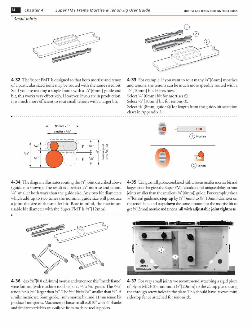
4-36 1⁄32 x 3⁄32"[0,8 x 2,4mm] mortise and tenons on this “match frame” were formed (with machine tool bits) on a 1⁄4"x 5⁄16" guide. The 15⁄32" tenon bit is 7⁄32" larger than 1⁄4". The 1⁄32" bit is 7⁄32" smaller than 1⁄4". A similar metric set: 6mm guide, 1mm mortise bit, and 11mm tenon bit produce 1mm joints. Machine tool bits as small as .010" with 1⁄4" shanks and similar metric bits are available from machine tool suppliers.
4-37 For very small joints we recommend attaching a rigid piece of ply or MDF ➀ minimum 3⁄4"[20mm] to the clamp plate, using the through screw holes in the plate. This should have its own mini sidestop fence attached for tenons ➁.
1
2
25Chapter 4MORTISE AND TENON ROUTING PROCEDURES Super FMT Frame Mortise & Tenon Jig User Guide
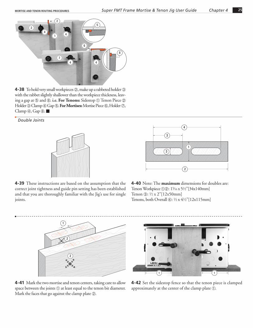
4-38 To hold very small workpieces ➁, make up a rabbeted holder ➂ with the rabbet slightly shallower than the workpiece thickness, leav-ing a gap at ➄ and ➇. i.e. For Tenons: Sidestop ➀ Tenon Piece ➁ Holder ➂ Clamp ➃ Gap ➄. For Mortises: Mortise Piece ➅, Holder ➆, Clamp ➃, Gap ➇. ■
1 44
4 4
3
7
2
6
8
5
4-39 These instructions are based on the assumption that the correct joint tightness and guide pin setting has been established and that you are thoroughly familiar with the Jig’s use for single joints.
4-40 Note: The maximum dimensions for doubles are:Tenon Workpiece ➀➁: 15⁄16 x 51⁄2"[34x140mm]Tenon ➂: 1⁄2 x 2"[12x50mm]Tenons, both Overall ➃: 1⁄2 x 41⁄2"[12x115mm]
3
4
13
2
4-41 Mark the two mortise and tenon centers, taking care to allow space between the joints ➀ at least equal to the tenon bit diameter. Mark the faces that go against the clamp plate ➁.
1
2
2
4-42 Set the sidestop fence so that the tenon piece is clamped approximately at the center of the clamp plate ➀.
11
Double Joints

26 Chapter 4 MORTISE AND TENON ROUTING PROCEDURESSuper FMT Frame Mortise & Tenon Jig User Guide
4-43 Sight the left hand tenon and lock the table ➀. Set and lock both FB limit stops against their stop post ➁. Set and lock only the right hand LR limit stop against its post ➂.
2
1
1
1
3
4-44 Unlock the table and sight the right hand tenon ➃ and lock the table. Set and lock the left hand LR limit stop against the post ➄. Release the table clamp and move the table left and right against the LR stops to double-check sight alignment to the two tenons. Remove the sight.
4
5
4-45 Move the table left and lock. Do not rout yet. While with practise it is fairly easy to avoid routing “into” the right tenon when routing the left ➀, we recommend that beginners use a small shop-made “guard” to prevent this ➁. Use 1⁄4"[6mm] thick MDF or plywood. Allow a 3⁄16"[5mm] gap between the end of the guide and guard ➂. Rout the left tenon.
12
3
4-46 Move the table right and lock. Lift the left end of the router and move the “tenon guard” left ➀. Rout the right hand tenon ➁. Repeat as required for all tenon ends, moving the table “guard” piece only once for each pair. Leave the table to the right. Remove and save the guard.
12
4-47 Replace the sight. Position and clamp the mortise piece so the right hand mortise of the first pair is centered under the sight ➀. Either mark an outrigger or set a stop block for successive mortise pieces ➁. Remove the sight and rout the right hand mortise.
2
1
4-48 Move the table left and lock. Rout the left hand mortise. Leave the table to left.
27Chapter 4MORTISE AND TENON ROUTING PROCEDURES Super FMT Frame Mortise & Tenon Jig User Guide
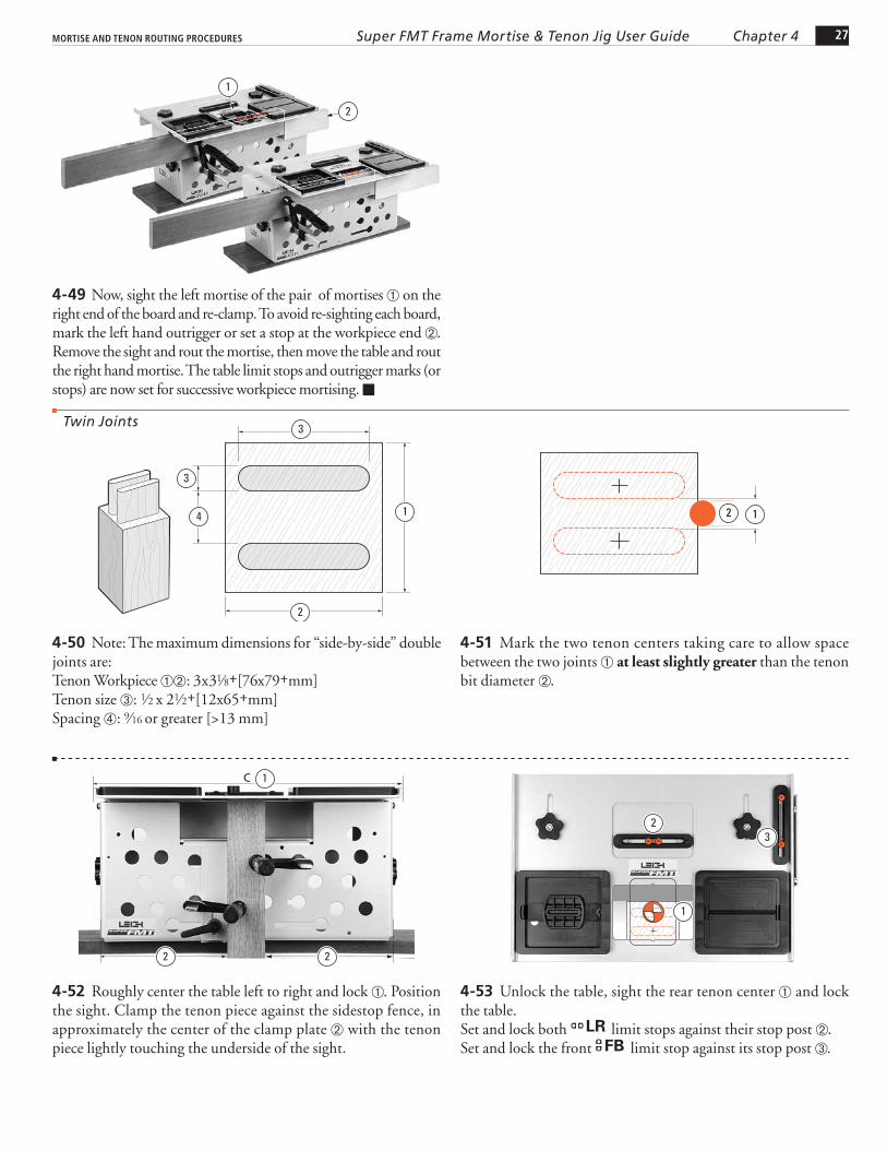
4-49 Now, sight the left mortise of the pair of mortises ➀ on the right end of the board and re-clamp. To avoid re-sighting each board, mark the left hand outrigger or set a stop at the workpiece end ➁. Remove the sight and rout the mortise, then move the table and rout the right hand mortise. The table limit stops and outrigger marks (or stops) are now set for successive workpiece mortising. ■
1
2
4-50 Note: The maximum dimensions for “side-by-side” double joints are:Tenon Workpiece ➀➁: 3x31⁄8+[76x79+mm]Tenon size ➂: 1⁄2 x 21⁄2+[12x65+mm]Spacing ➃: 9⁄16 or greater [>13 mm]
1
3
2
3
4
4-51 Mark the two tenon centers taking care to allow space between the two joints ➀ at least slightly greater than the tenon bit diameter ➁.
12
4-52 Roughly center the table left to right and lock ➀. Position the sight. Clamp the tenon piece against the sidestop fence, in approximately the center of the clamp plate ➁ with the tenon piece lightly touching the underside of the sight.
22
1C
4-53 Unlock the table, sight the rear tenon center ➀ and lock the table.Set and lock both LR limit stops against their stop post ➁.Set and lock the front FB limit stop against its stop post ➂.
23
1
Twin Joints

28 Chapter 4 MORTISE AND TENON ROUTING PROCEDURESSuper FMT Frame Mortise & Tenon Jig User Guide
4-54 Unlock the table and sight the front tenon ➃ and lock the table. Set and lock the rear FB stop against its post ➄. Unlock the table and move the table front to back against the stops to double-check the tenon sighting.
4
5
4-55 Move the table to the rear against the stop ➀, and lock. Do not rout yet. While with practise it is fairly easy to avoid routing into the front tenon ➁ when routing the rear, we recommend that beginners use a simple shop-made “guard” ➂ to prevent this. Use 1⁄4"[6mm] thick MDF or plywood. Allow a 3⁄16"[5mm] gap ➃ between the side of the guide and guard. Rout the rear tenon ➄.
4
3
1
2
5
4-56 Move the table forward against the rear limit stop and lock ➀. Lift the left end of the router and move the “tenon guard” to the rear ➁. Rout the front tenon ➂. Leave the table forward. Note: By using two or three left-right table positions, (in addition to the front-back posi-tions), the workpiece width and tenon width may be increased to the maximum (see this Chapter, Longer and Shorter Joints).
3
1
2
4-57 Mortises Position the sight. Position and clamp the mortise piece so the left end front mortise is centered under the sight ➀. Either mark the right hand outrigger beam or set a stop block for successive mortise pieces ➁. Rout the front mortise.
1
2
4-58 Move the table back against its stop ➀ and lock. Rout the rear mortise ➁. Leave the table back.
1
2
4-59 Replace the sight, unclamp and move the mortise board left so that the rear mortise of the pair at the right end of the piece is centered under the sight ➀, and re-clamp. Mark the left hand outrigger or set a stop ➁ adjacent to that end of the workpiece. Rout first the rear mortise at this (right hand) end, then move the table and rout the front mortise. The outrigger marks or stops are now set up for successive workpiece mortising. ■
2
1

29Chapter 4MORTISE AND TENON ROUTING PROCEDURES Super FMT Frame Mortise & Tenon Jig User Guide
4-60 The maximum dimensions for quadruple joints are:Tenon Workpiece ➀: 3" x 51⁄2"[70 x 140mm]Tenon Size ➁: 1⁄2 x 2"[12 x 50mm]Center Spacing ➂: 11⁄2 x 21⁄2"[38 x 63mm].
2
3 3 1
1
2
4-61 Tenons Mark the four tenon and mortise centers to suit your layout. Take care to leave a space between tenons ➀ at least slightly greater than the tenon bit diameter ➁.
1
1
2
4-62 Center (approximately) ➀ and clamp the tenon board on the clamp plate and set the sidestop fence.
11
4-63 Position the sight, release the table clamp and move the table to sight the left hand front tenon ➀. Lock the table. Move the right hand LR stop to its post and lock ➁. Move the back
FB stop to its post and lock ➂.
2
3
1
1
4-64 Release and move the table to sight the rear left hand tenon ➀. Note: Ensure the LR post is still touching the right hand limit stop ➁. Lock the table. Move the front FB stop to its post and lock ➂.
231
1
4-65 Unlock the table and move to the rear right-hand tenon and sight ➀. Note: ensure the FB post is still touching the front limit stop ➁. Lock the table. Move the left hand LR stop to its post and lock ➂.
321
1
Quadruple Joints

30 Chapter 4 MORTISE AND TENON ROUTING PROCEDURESSuper FMT Frame Mortise & Tenon Jig User Guide
4-66 All four stops are now set ➀ and provided you have sym-metrically marked out the joint, moving the table to the front right hand tenon, the sight should automatically align with that mark ➁. If it does not, do not change anything. Just check the other three positions—the actual joint will be symmetrical.
1
1
2
2
4-67 With practice, it is fairly easy to avoid routing into an adjoin-ing tenon, however, we do recommend that beginners use a simple “L”-shaped shop made guard to prevent this ➀. Use 1⁄4"[6mm] MDF or plywood and allow a 3⁄16"[5mm] gap between the guide and guard. Rout the front right tenon ➁.
1
2
4-68 Move the table to the front left against the stops and lock ➀. With the “guard” at the rear right ➁, rout the front left tenon ➂.
1
2
3
4-69 Move the table to the rear left, and lock ➀. Move the “guard” to the front right ➁. Rout the rear left tenon ➂.
11 1
2
3
4-70 Move the table to the rear right against the stops and lock ➀. Move the “guard” to the front left ➁. Rout the rear right tenon ➂. Rout all other tenon ends required. leave the table to the rear right.
1 1 11
2
3
4-71 Mortises Extend the sight, position and clamp the mortise board so that the rear right mortise is centered under the sight ➀. Either mark an outrigger or set a stop-block for successive mortise boards ➁. Rout all four mortises in their respective positions ➂. Note: The Super FMT vacuum port may prove ineffective on wide mortise pieces, particularly on the front mortises. ■
22
31

31Chapter 4MORTISE AND TENON ROUTING PROCEDURES Super FMT Frame Mortise & Tenon Jig User Guide
4-72 Because of safety considerations it is only practical to rout triple joints with 3⁄8" bits and guides or smaller.Maximum dimensions for triple joints are:Tenon Workpiece ➀: 13⁄4 x 51⁄2"[44 x 140mm]Tenon Size ➁: 3⁄8 x 2"[10 x 50mm]Center Spacing ➂: 7⁄8 x 21⁄2"[22 x 63mm].
1
2
3
3
1
2
4-73 Mark the three tenon and mortise centers, taking care to leave a space between tenons at least slightly greater than the tenon bit diameter ➀.
1
1
4-74 Tenons Center (approximately) and clamp the tenon workpiece on the clamp plate ➀ and set the sidestop fence.
11
4-75 Fit the sight, release the table clamp and sight the front tenon of the pair ➀. Lock the table, move the right hand LR limit stop to the post and lock ➁. Move the back FB limit stop to the post and lock ➂.
23
1
1
4-76 Release the table clamp and sight the rear tenon of the pair ➀, making sure that the right-hand LR stop is against its post ➁. Lock the table. Move the front FB limit stop to its post and lock ➂.
231
1
4-77 Loosen the table clamp and move the table to sight the third (single) tenon ➀. Lock the table. Set and lock the left hand
LR limit stop to its post ➁. Cut a small hardwood block to the following size: Width ➂ 3⁄8"[13mm], Depth 5⁄16"[8mm], Length ➄: Cut to length to a snug fit between the rear FB limit stop and its stop post. This block will be used for the “third” tenon position.
21
5
3
1
Triple Joints

32 Chapter 4 MORTISE AND TENON ROUTING PROCEDURESSuper FMT Frame Mortise & Tenon Jig User Guide
4-78 Rout the left pair of tenons in the same way as for the qua-druple tenons ➀ (4-68 and 4-69), using the Limit Stops ➁ and an L-shaped guard ➂ in the guard recess, to prevent accidental routing of adjacent tenons.
m Do not attempt routing the third tenon before reading on.
2
2
13
2
2
31
4-79 m If the tenon rail is thicker than 15⁄16"[34mm] (as is most likely with this joint type), then great care must be exercised not to “trap” the bit ➀ when routing the third tenon. i.e. The bit would have to be plunged into the side of the tenon board. This could result in the bit “driving” itself across the board which could be dangerous.
1
4-80 So to reduce the thickness, move the table right and rearward against the stops ➀ as if to rout a quadruple tenon. Then add a small “guard” piece ➁ to the L-shaped guard in the guide recess. Now rout away part of the workpiece ➂.
1
1
3
2
4-81 Move the table forward, keeping it to the right ➀. Flip the guards to the back ➁. Now rout away the front right part of the workpiece ➂.
11
3
2
4-82 Loosen the table clamp. With the table to the right, against the LR stop, put the small block between the rear FB stop and its post ➀. You must always use the same limit stop for all other third tenons and mortises. Using a guard to avoid routing into the other two tenons ➁, rout the rest of the third tenon ➂.
11
2
3
4-83 m Mortises Triple mortises are routed the opposite way around. If the single tenon is to the right ➀, the single mortise must be to the left ➁, and vice versa, using the same block on the same side of the stop post ➂.
3
2
1
33Chapter 4MORTISE AND TENON ROUTING PROCEDURES Super FMT Frame Mortise & Tenon Jig User Guide
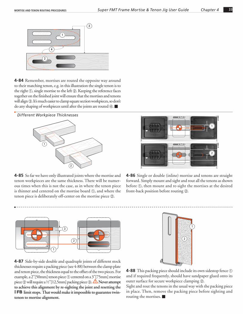
4-84 Remember, mortises are routed the opposite way around to their matching tenon, e.g. in this illustration the single tenon is to the right ➀, single mortise to the left ➁. Keeping the reference faces together on the finished joint will ensure that the mortises and tenons will align ➂. It’s much easier to clamp square section workpieces, so don’t do any shaping of workpieces until after the joints are routed ➃. ■
2
1
4
3
4-85 So far we have only illustrated joints where the mortise and tenon workpieces are the same thickness. There will be numer-ous times when this is not the case, as in where the tenon piece is thinner and centered on the mortise board ➀, and where the tenon piece is deliberately off-center on the mortise piece ➁.
1
2
4-86 Single or double (inline) mortise and tenons are straight forward. Simply mount and sight and rout all the tenons as shown before ➀, then mount and re-sight the mortises at the desired front-back position before routing ➁.
2
1
4-87 Side-by-side double and quadruple joints of different stock thicknesses require a packing piece (see 4-88) between the clamp plate and tenon piece, the thickness equal to the offset of the two pieces. For example, a 2"[50mm] tenon piece ➀ centered on a 3"[75mm] mortise piece ➁ will require a 1⁄2"[12,5mm] packing piece ➂. m Never attempt to achieve this alignment by re-sighting the joint and resetting the
FB limit stops. That would make it impossible to guarantee twin-tenon to mortise alignment.
3
2
1
4-88 This packing piece should include its own sidestop fence ➀ and if required frequently, should have sandpaper glued onto its outer surface for secure workpiece clamping ➁.Sight and rout the tenons in the usual way with the packing piece in place. Then, remove the packing piece before sighting and routing the mortises. ■
2
1
Different Workpiece Thicknesses

34 Chapter 4 MORTISE AND TENON ROUTING PROCEDURESSuper FMT Frame Mortise & Tenon Jig User Guide
4-89 The Super FMT table movement allows for easy routing of odd-sized joints. For example, you may want to rout a 3"[75mm] joint ➁ and you only have a 2"[50mm] guide ➀. Use this simple formula:Joint, minus Guide, divided by 2.Example: 3" - 2" ÷ 2 = 1⁄2"[75 - 50 ÷ 2 = 12,5mm]Cut a small block equal to the result; in this example, 1⁄2"[12,5mm].
Longer and Shorter Joints
1
2
4-90 Tenons Mark the center Position and sight the tenon ➀, and lock the table. Set the FB stops against the post ➁.
2
1
4-91 Set the LR stops one at a time with the small block between the stops and post ➀ ➁. This ensures that the table move-ment is centered about the joint center mark on the stock. Remove the block, but save it.
12
4-92 To rout the wider tenon: Move the table right, to the stop ➀.Rout the right hand end of the tenon ➁. Use a guard in the left end of the guide recess if necessary ➂.
1
3 2
4-93 Move the table left to the stop ➀. Rout the left hand end of the tenon ➁. If you’re using a “guard”, flip it to the right end of the recess ➂. Repeat for all required tenons.
3
1
2
4-94 Mortises Loosen the table clamp. Use the small block between one stop and the stop post ➀ and lock the table. Center a mortise piece under the sight, and clamp ➁. Set sidestop blocks or marks on the outriggers ➂.
3
1
2

35Chapter 4MORTISE AND TENON ROUTING PROCEDURES Super FMT Frame Mortise & Tenon Jig User Guide
4-95 Move the table right to the stop ➀. Rout the right-hand end of the mortise ➁, using the full length of the mortise guide.
1
2
4-96 Move the table left to its stop ➀. Rout the left-hand end of the mortise ➁. Repeat for all required mortises. To recap: for joints longer than the guides, move the table right and rout right, move the table left and rout left.
1
2
4-97 For mortises and tenons shorter than the guide, reverse the calculation: Guide, minus Joint, divided by 2. Example: you may want a 1"[25mm] joint ➀ using a 2"[50mm] guide ➁. 2" - 1" ÷ 2 = 1⁄2" [50mm - 25mm ÷ 2 = 12,5mm]. Make a block 1⁄2"[12,5mm]. You will also need a short length of 3⁄16"[5mm] dowel ➂ to act as a guard when routing the mortises.
2
3
1
4-98 Tenons Setting the block and limit stops for the shorter tenons procedure ➀ ➁ is exactly the same as for longer tenons setup, except when you come to rout…
12
4-99 …Then it is:Move table right; rout to the left ➀. Move table left; rout to the right ➁. Again, use a guard in the guide recess if necessary.
1
1
2
2
4-100 Mortises The rule is the same for mortises except you will need to use a small piece of that 3⁄16"[5mm] dowel as a guard in the guide’s mortise slot ➀. The dowel should be slightly longer than the difference between the guide length and joint length; in this example, slightly longer than 1"[25mm]. In this example, the joint is only 1" long and the guide mortise slot is 2". Therefore you need a guard dowel to prevent cutting a mortise longer than required.
1

36 Chapter 4 MORTISE AND TENON ROUTING PROCEDURESSuper FMT Frame Mortise & Tenon Jig User Guide
4-101 For the shorter mortises: Table right; dowel right; rout left side ➀. Table left; dowel left; rout right side ➁. The length of the dowel guard allows you to rout a mortise slightly shorter than required in the first cut and to clean out in the second cut.
1
1
2
2
4-102 To rout long vertical boards you could build a jig stand to mount on your bench. Make the stand/bench combination high enough to accept the desired board length, bolted securely to the bench. Make a stable platform as shown here to stand on. Don’t use a fold-ing step, it is unstable. Other novel solutions: holes in (suspended) floor; jig bolted to deck or mezzanine railing; wall brackets.
4-103 Wider and Thicker boards Make this bracket to mount and mortise a wide board face, clamp pieces greater than Leigh Clamp 3" capacity, and center mortises on boards up to 45⁄8"[115mm] wide or even 63⁄8"[162mm].
1
54
3 6
2
4-104 Use carriage bolts and nuts to secure the bracket to the Super FMT clamp face and adjust the distance below the table to slightly greater than the mortise piece thickness ➀.
1
1
4-105 Use C-clamps or F-Clamps to hold the workpiece onto the bracket, with the workpiece rear edge touching the clamp plate. Now raise the bracket so the workpiece touches the underside of the table. Tighten the clamp plate nuts. The widest board in which a mortise may be centered is 45⁄8"[115mm] ➀.The thickest depth capacity is 5"[100mm] ➁.
2
1
4-106 Mortises in center of boards 45⁄8" to 61⁄2"[115-165mm] ➀: Mark the mortise center on a test board ➁. Using the guide recess front edge as mortise guide ➂, adjust the table to center the mortise. Control mortise length with 3⁄16"[5mm] dowel pieces in the pin track ➃ (see 4-100). Note: This is not a standard Leigh solution, but we thought it would solve this rare challenge. ■
21
4
➀ 41⁄2"[115mm]➁ 24"[600mm]
➂ 43⁄4"[120mm]➃ 9"[230mm]
➄ 2"[50mm]➅ 3⁄4"[20mm]

37Chapter 4MORTISE AND TENON ROUTING PROCEDURES Super FMT Frame Mortise & Tenon Jig User Guide
4-107 The majority of frame joints are at 90˚ ➀ but the abil-ity to angle joints is essential in chair construction, for example. Whether these joints are single angles ➁ and ➂ or a compound angle ➃ they are easily achieved on the Super FMT.
90˚45˚
90˚45˚
10˚
12
34
10˚
4-108 Angling the sidestop fence gives a single angled joint in the left-right direction.
4-109 Angling the clamp plate ➀ with the sidestop in a vertical position ➁ gives a single angled joint in the front-back direc-tion.
1
2
4-110 Angling both the sidestop fence and clamp plate gives a double or compound angled joint.
4-111 The Super FMT clamp plate can be angled up to 30˚ but it is doubtful you will ever need to approach even 10˚ on a mortise and tenon joint. The strength of a tenon across its grain lessens consider-ably as the angle increases ➀. In addition, the length and position of the tenon is limited in slope by the angled workpiece relative to the vertical bit ➁ (angle demonstrated in this illustration is excessive).
1
2
4-112 However, you may for example, want to machine spline mortises or dowel holes in a stave type construction in, say, octa-gons at 221⁄2˚, or hexagons at 30˚, so the 30˚ capacity may prove to be useful. You can then machine precisely fitting splines on the Super FMT and trim them to length. ■
Angled Joints

38 Chapter 4 MORTISE AND TENON ROUTING PROCEDURESSuper FMT Frame Mortise & Tenon Jig User Guide
4-113 Through Tenons Occasionally, a design feature will call for through, exposed tenons, possibly “wedged” for decorative effect. The limited depth of cut of router bits can make this difficult, but the two-sized bit technique described previously, combined with the precision of the Super FMT, makes this procedure perfectly feasible in many instances.
4-114 The problem with through mortises is their great depth relative to the cutting depth and diameter of the bit. However, if the left-right part of the joint center mark ➀ is carefully squared around the mortise workpiece, it is possible to accurately plunge from both sides.
1
4-115 Here’s an example:1⁄4"[6mm] joint through 11⁄2"[35mm] deep mortise.Select 1⁄4"[6mm] bit for mortises ➀.Select 1⁄2"[12mm] bit to rout the 11⁄2"[35mm] long tenon ➁.Select 3⁄8"[8mm] guide ➂ for length from the guide/bit selection chart in Appendix I.
1
2
3
4-116 Carefully sight the mortise taking particular care to center the “vertical” line ➀ in the sight. Plunge and rout down deeper than half the mortise board depth but no more than the cutting length of the bit.
1
4-117 Turn the mortise piece end for end and, keeping the same reference side of the mortise board to the clamp face, carefully sight the “vertical” mortise center mark ➁ and lock the table . Plunge and rout to clear the through mortise.
2
4-118 Rout the tenons with the larger (longer) bit slightly deeper than the mortise depth.
Through Tenons

39Chapter 4MORTISE AND TENON ROUTING PROCEDURES Super FMT Frame Mortise & Tenon Jig User Guide
4-119 It may even be possible to make tenons long enough to be raised if this decorative effect is desired. “Wedging” the tenons is a simple hand procedure and adds a nice decorative touch. By design, mortise length is slightly greater than tenon width. Wedging expands the tenon to eliminate the gap.
4-120 If the tenon stock is smaller than the table opening it may be possible (after sighting) to slide the tenon workpiece up to gain an extra 1⁄2" ➀ [12mm] of tenon length (assuming of course that the bit has sufficient cutting depth) but no higher than the top of the guide moldings ➀. ■
1
4-121 Routing bridle joints on the Super FMT is simple. All the workpieces (with the exception of the mitered tenon) ➀ are mounted vertically on the jig. Fit for bridle joints is adjusted with the left guide pin.
1
4-122 Select a guide that is greater in length than the workpiece width ➀ by at least two bit diameters. Rout right through the “vertical mortise” ➁ and across the tenon sides ➂. The bit will clear the edge of the workpiece before the guide pin reaches the rounded part of the guide. Adjustment for fit is made with the left hand guide pin.
Mortise
Tenon
2
3
1
4-123 The mitered “tenon” is mounted at 45˚ on the clamp plate ➀. The “mortise” end miter ➁ is cut on the table saw after routing the mortise.
1
2
4-124 Twin bridle joints use the technique described above combined with the table movement ➀ described in Twin Joints, 4-50.
1
Bridle Joints

40 Chapter 4 MORTISE AND TENON ROUTING PROCEDURESSuper FMT Frame Mortise & Tenon Jig User Guide
4-125 Floating Tenons A “floating” tenon in a mitered corner allows for a greater joint glue area at the inside of the corner. On this mitered corner, the workpieces are mounted in the jig at 45˚ and the mortises routed. The floating tenon ➀ is routed on the end of a vertically mounted scrap piece using the same guide and then sawn off. ■
1
4-126 Asymmetric Tenons Not all tenons are centered on the long axis of the workpiece end ➀. This means that tenons “A” are routed at one table sighting and tenons “B” at a second table sighting. If they aren’t routed in this manner, the two tenons will be diagonally opposed to each other ➁.
B
A
A
2
B
1
4-127 Use the LR limit stops for rapid changeover from tenons “A” to tenons “B”.For example, with the workpiece centered on the jig, sight tenon “A” and set the right hand limit stop to the right of the post ➀, then…
1
4-128 …sight tenon “B” and set the left hand limit stop to the left of the post ➀. Now alternately rout tenons “A” and “B”, moving the table left and right each time, or…
1
4-129 …if you don’t trust yourself to get the sequence correct, you could rout all the “A” tenons first, then change the table one time to rout all the “B” tenons. This latter procedure would be the simplest way to rout haunched tenons (covered in the next section). ■
B
A
Asymmetric Tenons

41Chapter 4MORTISE AND TENON ROUTING PROCEDURES Super FMT Frame Mortise & Tenon Jig User Guide
4-130 Haunched Joints Frame and panel door construction can call for rails and stiles to be grooved for the panel ➀, and the tenons haunched ➁, both for joint stability and to fill the end of the stile groove which is sometimes run right through ➂. This is not as common as it once was. Routers and router tables now make it simple to have a stopped groove ➃, avoiding the need for the haunch.
1
4 3
1
2
4-131 Haunched mortises and tenons are “handed”, and require separate setups for each. e.g. if these two tenons ➀ were routed with the same jig setup, the result would be offset tenons ➁. So mark out the two types of corners as “A” and “B” mortises and tenons.
B
A
A1
1 2
B
4-132 First, groove all the workpieces ➀. The groove should be less than the mortise width ➁ and shallower than the haunch recess ➂.
1
3
2
4-133 Sight both the “A” and “B” mortises. Set stops or mark the outrigger for repeatable successive workpieces. Position and lock the FB Limit Stops against the post.
BA
4-134 “A” Mortises and Haunch Recesses Set right hand LR Limit Stop away from the post, 3⁄4 of the guide length ➀. e.g. 1"
guide, move 3⁄4". Table still in “mortise center” position, rout mortise full depth ➁. Raise the plunge. Move table left to the stop ➂. Lower the bit to haunch depth; set router depth turret. The router is now set for both depths of cut. Rout haunch recess ➃. Repeat for all “A” mortises.
2
13
4
4-135 “B” Mortises and Haunch Recesses Move the table left to touch the right hand LR Limit Stop against the post ➀ and lock the table. Move the left hand LR Limit Stop (by 3⁄4 of the guide length) to the left ➁. Rout the “B” mortises ➂ and haunch recesses ➃ using the table movement and the same router depth settings.
2 1
3 4
Haunched Joints

42 Chapter 4 MORTISE AND TENON ROUTING PROCEDURESSuper FMT Frame Mortise & Tenon Jig User Guide
4-136 Routing the Tenons Mark the tenon centers “A” and “B”. Remember, the tenons are “off center” and each end of the tenon pieces are marked off center in opposite directions. Prepare and make a couple of extra (scrap) tenon pieces to use in setting haunch bit depth later (4-137).
BA
4-137 “A” Tenons With the workpiece centered on the jig, sight the tenon center and set the right hand LR limit stop to the post ➀.
1
4-138 Move the table right to a position where the bit will clear the end of the haunch ➀ while the guide pin is still on the straight part of the guide ➁. Set the left hand LR limit stop to its post ➂.
3
12
4-139 Move the table to the left again and if necessary, set a “guard” piece in the guide recess ➀ to prevent routing around the right end of the tenon ➁. Rout the left end of the tenon (shaded area) at full shoulder depth.
1
2
4-140 Move the guard to the left end of the recess. Move the table right and rout the rest of the “A” tenon at full depth; the bit prevented from rounding the haunch off at ➀ by the guide pin against the guide side at ➁.
12
4-141 Move the table left, remove the guard from the bit recess. Depth: You will have to preset the plunge router depth-of-cut rod and turret so that the routed haunch exactly equals the depth of the haunch recess ➀. Use the scrap test tenons to achieve this setting by measurement and a little trial and error. Now rout completely around the actual tenon.
1
1

43Chapter 4MORTISE AND TENON ROUTING PROCEDURES Super FMT Frame Mortise & Tenon Jig User Guide
4-142 “B” Tenons on the other end are routed with the pro-cedure reversed. ■
5
1 2 3
4 5
4-143 Doweling Sometimes where the strength of a mortise and tenon is not required, doweling may be a suitable alternative. A bonus use of the Super FMT is its ability to provide very precise dowel hole boring. Turn the left hand guide pin down to “zero free play” in the mortise guide slot. Simply use one or both ends of a mortise guide slot for positioning while plunging the dowel holes. ■
Doweling

44 Chapter 4 Frame Mortise & Tenon Jig User Guide MORTISE AND TENON ROUTING PROCEDURES