FPGA-BASED HARDWARE EMULATION OF IMAGE MORPHING FINAL PRESENTATION CprE 583, Fall 2011
Upload
soumian-narayananCategory
view
217download
0
8/20/2019 Morphing BlDE Final
http://slidepdf.com/reader/full/morphing-blde-final 1/21
Detailed Design of a Morphable Wind Turbine Blade
Master-1, SMA (Applied Mechanics), Ecole Centrale de Nantes
A Presentation on the
on
04-06-2014
by
Shitij Arora
8/20/2019 Morphing BlDE Final
http://slidepdf.com/reader/full/morphing-blde-final 2/21
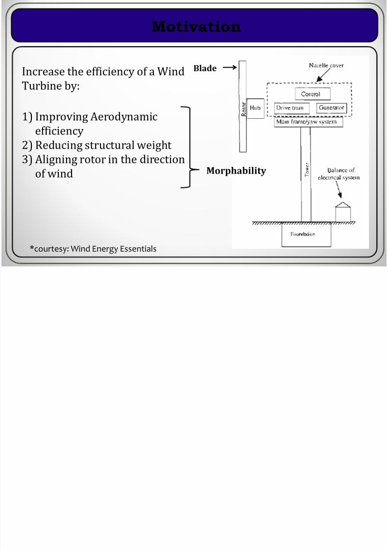
Motivation
BladeIncrease the efficiency of a WindTurbine by:
1) Improving Aerodynamic
efficiency2) Reducing structural weight
3) Aligning rotor in the direction
of wind Morphability
*courtesy: Wind Energy Essentials

8/20/2019 Morphing BlDE Final
http://slidepdf.com/reader/full/morphing-blde-final 3/21
Design Procedure
Step 1Choosing Power for the turbine and Estimating the size of Rotor
0
5
10
15
20
25
30
12345678910
R a
d i u s o f R o t o r i n m e t r e s
Power Rating in 10-1 Megawatts
Variation of Rotor size with Power Rating
I choose this
Power= 0.1 MW
Radius= 9.0952 m
For achieving Betz Limit (CP=0.59), efficiency 80% and Wind velocity 11 m/s
P (in MW)Power Cp eff density pi R U
0.1 100000 0.59 0.8 1.225 3.141593 9.095194 11
0.2 200000 0.59 0.8 1.225 3.141593 12.86255 11
0.3 300000 0.59 0.8 1.225 3.141593 15.75334 11
0.4 400000 0.59 0.8 1.225 3.141593 18.19039 11
0.5 500000 0.59 0.8 1.225 3.141593 20.33747 11
0.6 600000 0.59 0.8 1.225 3.141593 22.27859 11
0.7 700000 0.59 0.8 1.225 3.141593 24.06362 11
0.8 800000 0.59 0.8 1.225 3.141593 25.72509 11
0.9 900000 0.59 0.8 1.225 3.141593 27.28558 11
1 1000000 0.59 0.8 1.225 3.141593 28.76153 11

8/20/2019 Morphing BlDE Final
http://slidepdf.com/reader/full/morphing-blde-final 4/21
Design Procedure
Step 2 Choosing a tip Speed ratio (l) for the blade (the ratio between the angular
velocity of wind to the wind velocity) = 6
No of Blades chosen = 3
Airfoil profile: Symmetric profile (no camber) = NACA0018 near hub,
NACA0015 in middle of blade span and NACA0012 near the tip
Taking design value of angle of attack afor which CL/CD ratio is maximum, takecorresponding value of CL from standard tested values for NACA profile
Cldesign 0.65
Alpha 7

8/20/2019 Morphing BlDE Final
http://slidepdf.com/reader/full/morphing-blde-final 5/21
Design Procedure
= (2 3 )−(1 )
=
8
(1 ) Vary with span
Step 3 Calculate relative wind angle distribution and chord length distribution along its span
(radius r on total radius R), for maximizing efficiency, is calculated using formula:
=
Blade Twist is given by:
Chord length is given by:
8/20/2019 Morphing BlDE Final
http://slidepdf.com/reader/full/morphing-blde-final 6/21
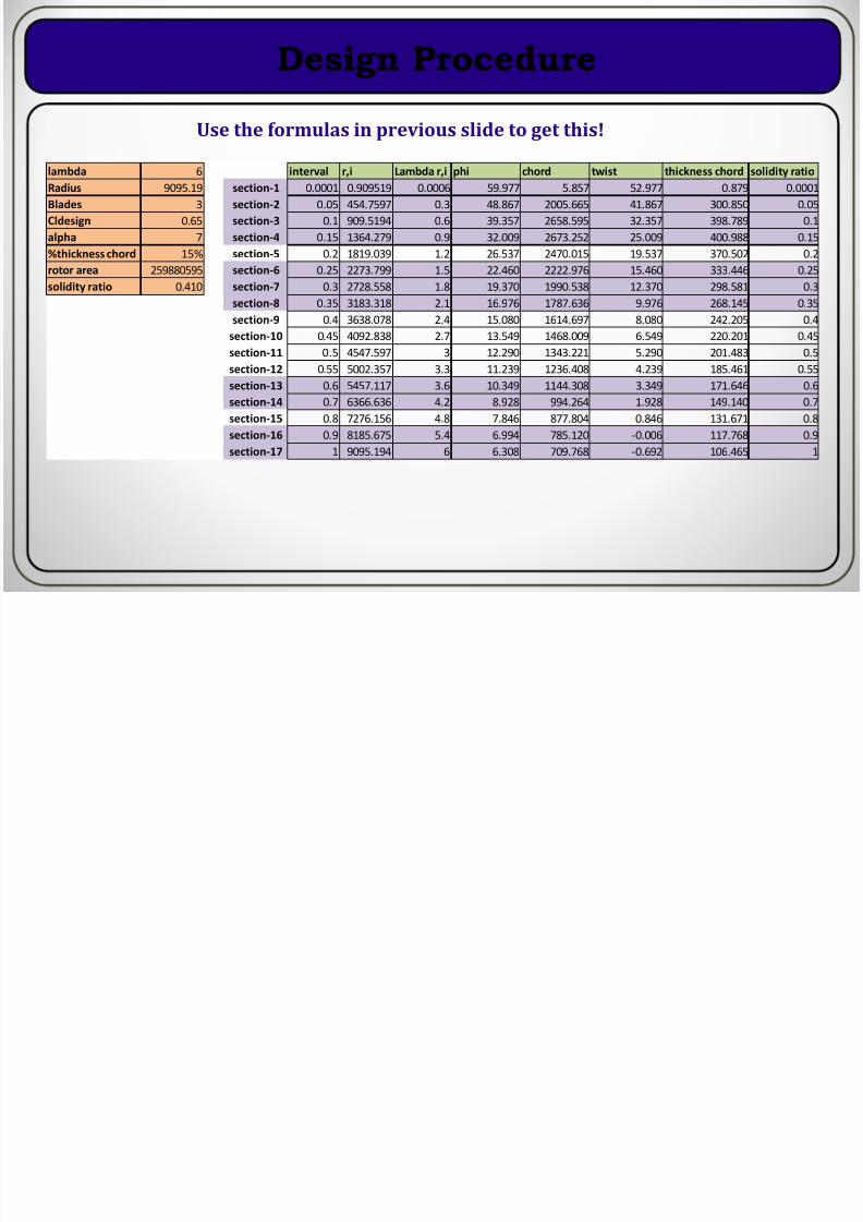
Design Procedure
lambda 6 interval r,i Lambda r,i phi chord twist thickness chord solidity ratio
Radius 9095.19 section-1 0.0001 0.909519 0.0006 59.977 5.857 52.977 0.879 0.0001
Blades 3 section-2 0.05 454.7597 0.3 48.867 2005.665 41.867 300.850 0.05
Cldesign 0.65 section-3 0.1 909.5194 0.6 39.357 2658.595 32.357 398.789 0.1
alpha 7 section-4 0.15 1364.279 0.9 32.009 2673.252 25.009 400.988 0.15
%thickness chord 15% section-5 0.2 1819.039 1.2 26.537 2470.015 19.537 370.502 0.2
rotor area 259880595 section-6 0.25 2273.799 1.5 22.460 2222.976 15.460 333.446 0.25
solidity ratio 0.410 section-7 0.3 2728.558 1.8 19.370 1990.538 12.370 298.581 0.3
section-8 0.35 3183.318 2.1 16.976 1787.636 9.976 268.145 0.35
section-9 0.4 3638.078 2.4 15.080 1614.697 8.080 242.205 0.4
section-10 0.45 4092.838 2.7 13.549 1468.009 6.549 220.201 0.45
section-11 0.5 4547.597 3 12.290 1343.221 5.290 201.483 0.5
section-12 0.55 5002.357 3.3 11.239 1236.408 4.239 185.461 0.55
section-13 0.6 5457.117 3.6 10.349 1144.308 3.349 171.646 0.6
section-14 0.7 6366.636 4.2 8.928 994.264 1.928 149.140 0.7
section-15 0.8 7276.156 4.8 7.846 877.804 0.846 131.671 0.8
section-16 0.9 8185.675 5.4 6.994 785.120 -0.006 117.768 0.9
section-17 1 9095.194 6 6.308 709.768 -0.692 106.465 1
Use the formulas in previous slide to get this!

8/20/2019 Morphing BlDE Final
http://slidepdf.com/reader/full/morphing-blde-final 7/21
8/20/2019 Morphing BlDE Final
http://slidepdf.com/reader/full/morphing-blde-final 8/21
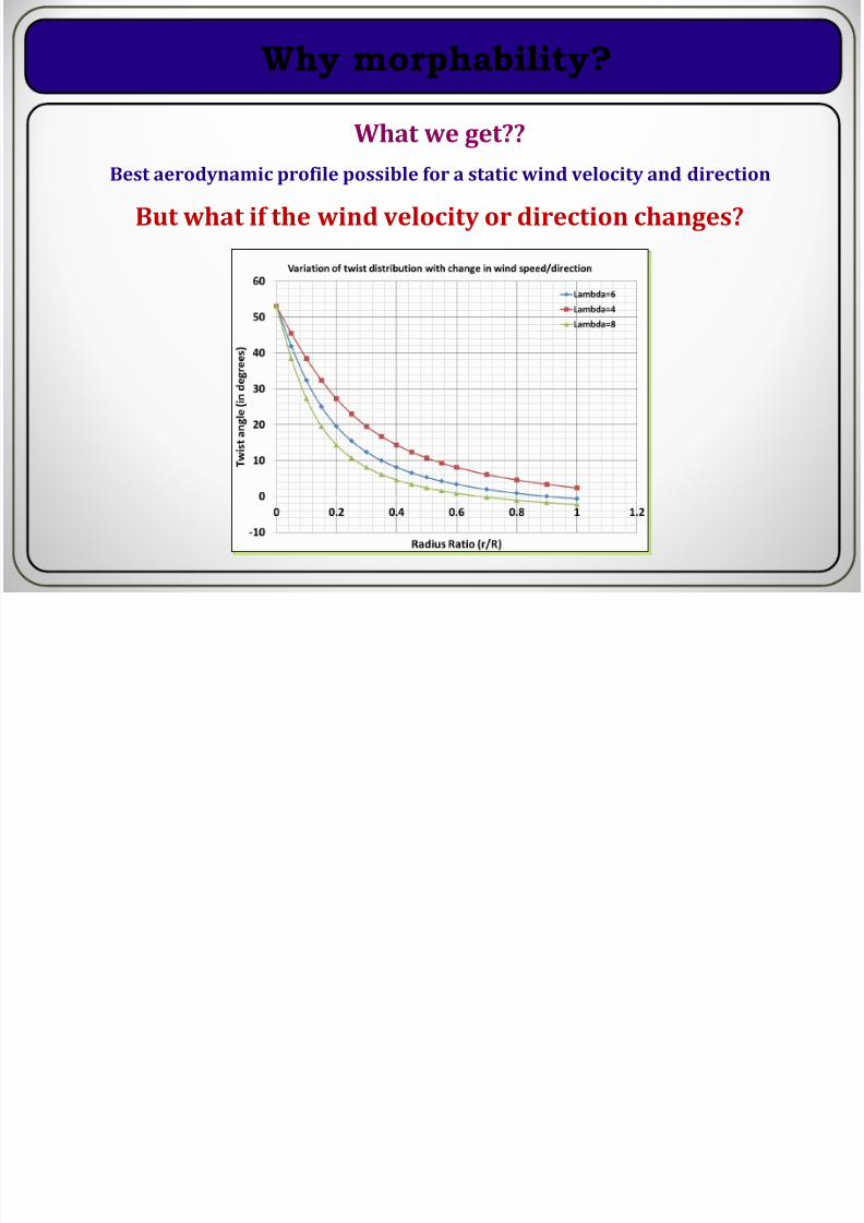
Why morphability?
What we get??
Best aerodynamic profile possible for a static wind velocity and direction
But what if the wind velocity or direction changes?

8/20/2019 Morphing BlDE Final
http://slidepdf.com/reader/full/morphing-blde-final 9/21
Morphability? Okay! but how?
Choose a morphable material for the blade (infinite DOFs in twist)
Choose a mechanism that changes the blade geometry (limited DOF)
Blade Material detailed Requirements:
The blade must be able to twist
It should be strong enough against the wind load
ANTAGONISTIC functional Requirements?
Use COMPOSITES!

8/20/2019 Morphing BlDE Final
http://slidepdf.com/reader/full/morphing-blde-final 10/21
Blade Skin Material
Steel reinforcement
Elastomer
Blade skin section
1. I choose blade skin made of high modulus elastomer (silica rubber)reinforced with steel wires (like or unlike tyres)
2. The steel wires give unidirectional strength in the sectional direction of the
blade
3. Elastomer gives ability to take up high degree of twist

8/20/2019 Morphing BlDE Final
http://slidepdf.com/reader/full/morphing-blde-final 11/21
Blade Morphing Mechanism
9 proposals for the mechanisms that can be used for morphing the blade
I choose the simplest of all: the TELESCOPIC Mechanism, with 3 concentric
shafts (3 DOFs) for transfering twist into the blade
Each shaft is rotated by a different motor at one end to a precise angular
requirement
Shaft-1
Shaft-3
Shaft-2
The twist at any section of the
blade skin, between two movers
can be found using this relation
=
+

8/20/2019 Morphing BlDE Final
http://slidepdf.com/reader/full/morphing-blde-final 12/21
Blade parts
Mechanism: 1 stator (AA2014-T651), 3 movers (AA2014-T651), 3 concentric
shafts (Ti-6Al-4V), 12 bearings (AISI 52100), 2 circlips (M250 Maraging steel)
Stator
Stator Mover-1
Mover-2
Mover-3

8/20/2019 Morphing BlDE Final
http://slidepdf.com/reader/full/morphing-blde-final 13/21
Blade parts
Shaft-1: OD 120 mm,
ID 88 mm
Shaft-2: OD 72 mm, ID 50 mm
Shaft-3: Dia 40 mm, ID 50 mm
Circlip [3]
Pretwist in the blade
Double row taper Roller
Bearing [3]
B l a d e s k i n w i t h
p r e t w i s t
B l a d e : m
o r p h a b l e s k i n
9085.7 mm
7066.64mm
4238.08mm
[ 3 ] h t t p : / / w w w . t r a c e p a r t s o n l i n e . n e t

8/20/2019 Morphing BlDE Final
http://slidepdf.com/reader/full/morphing-blde-final 14/21

8/20/2019 Morphing BlDE Final
http://slidepdf.com/reader/full/morphing-blde-final 15/21
Mechanism Assembly
Stator
Mover-1
Mover-2
Mover-3
Shaft-1
Shaft-2
Shaft-3
8/20/2019 Morphing BlDE Final
http://slidepdf.com/reader/full/morphing-blde-final 16/21
Complete Blade with the skin

8/20/2019 Morphing BlDE Final
http://slidepdf.com/reader/full/morphing-blde-final 17/21
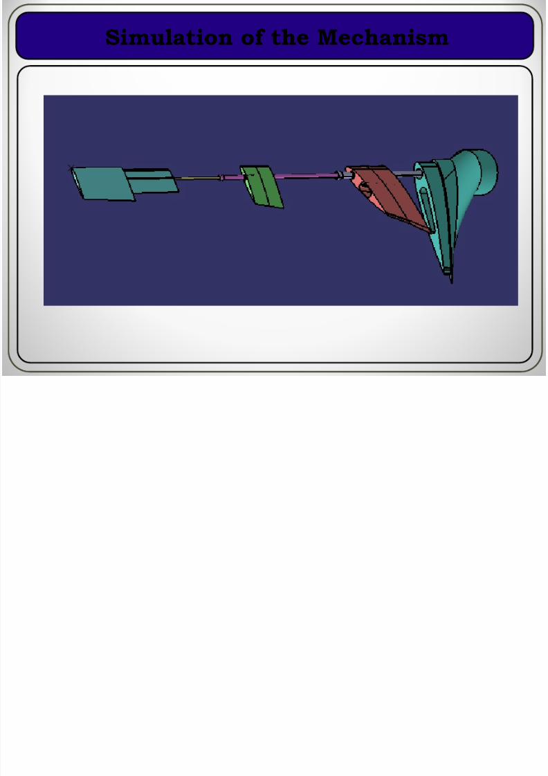
Simulation of the Mechanism
8/20/2019 Morphing BlDE Final
http://slidepdf.com/reader/full/morphing-blde-final 18/21
FE Structural Analysis
Platform: Ansys 12.0 63270 SHELL181 Elements, 189810 DOFs
Material property:
Orthotropic material property for the skinE11= 31GPa
E22= E33= 100MPa,
n12=0.31, n23=n13=0.4995
Aluminum Material: E= 70GPa, n=0.33
Linear Structural analysis
100% mapped meshing

8/20/2019 Morphing BlDE Final
http://slidepdf.com/reader/full/morphing-blde-final 19/21
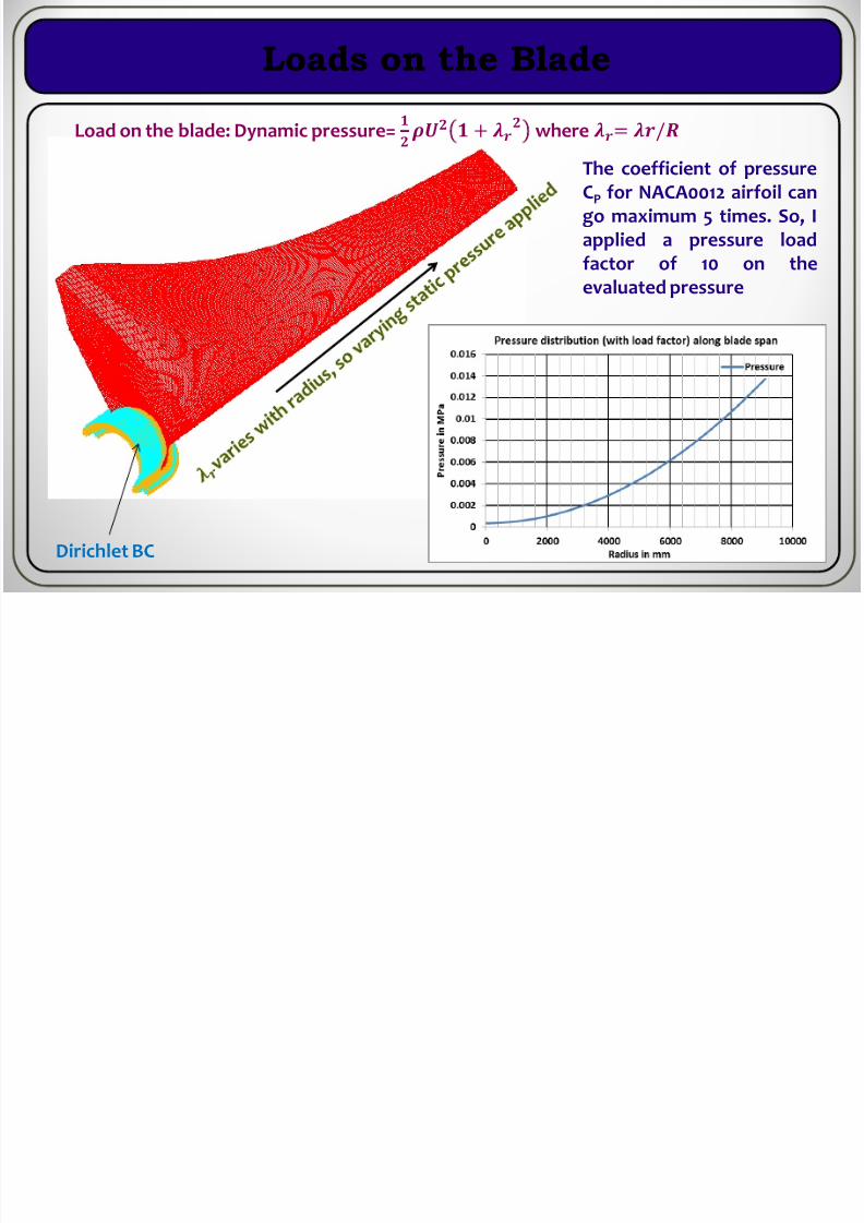
Loads on the Blade
Load on the blade: Dynamic pressure=
+
where = /
Dirichlet BC
The coefficient of pressure
CP for NACA0012 airfoil can
go maximum 5 times. So, I
applied a pressure load
factor of 10 on the
evaluated pressure

8/20/2019 Morphing BlDE Final
http://slidepdf.com/reader/full/morphing-blde-final 20/21
Results: Deformations and Stresses
Vector sum Displacements
Vonmises stress

8/20/2019 Morphing BlDE Final
http://slidepdf.com/reader/full/morphing-blde-final 21/21
Thank You!