More than just products BG 65 / Alles aus einer Hand BG 65 PDFs/Dunkermotoren/BG Sections/BG… ·...
27
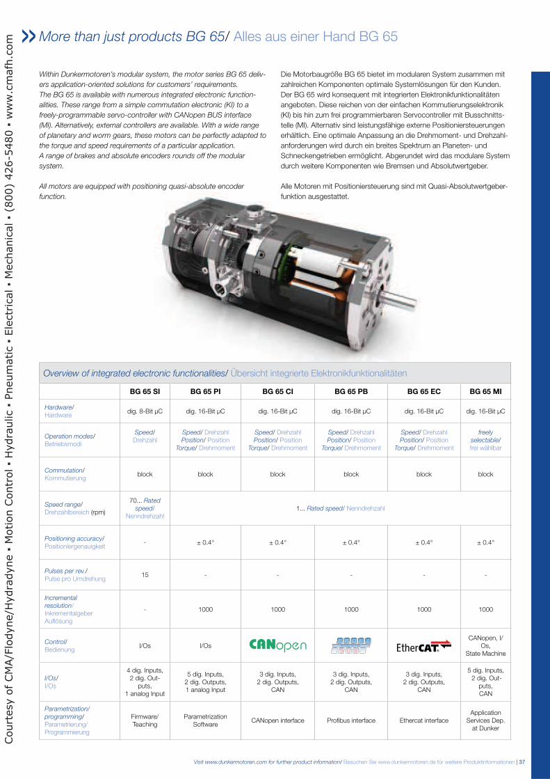
Visit www.dunkermotoren.com for further product information/ Besuchen Sie www.dunkermotoren.de für weitere Produktinformationen | 37 More than just products BG 65/ Alles aus einer Hand BG 65 Within Dunkermotoren’s modular system, the motor series BG 65 deliv- ers application-oriented solutions for customers’ requirements. The BG 65 is available with numerous integrated electronic function- alities. These range from a simple commutation electronic (KI) to a freely-programmable servo-controller with CANopen BUS interface (MI). Alternatively, external controllers are available. With a wide range of planetary and worm gears, these motors can be perfectly adapted to the torque and speed requirements of a particular application. A range of brakes and absolute encoders rounds off the modular system. All motors are equipped with positioning quasi-absolute encoder function. Die Motorbaugröße BG 65 bietet im modularen System zusammen mit zahlreichen Komponenten optimale Systemlösungen für den Kunden. Der BG 65 wird konsequent mit integrierten Elektronikfunktionalitäten angeboten. Diese reichen von der einfachen Kommutierungselektronik (KI) bis hin zum frei programmierbaren Servocontroller mit Busschnitts- telle (MI). Alternativ sind leistungsfähige externe Positioniersteuerungen erhältlich. Eine optimale Anpassung an die Drehmoment- und Drehzahl- anforderungen wird durch ein breites Spektrum an Planeten- und Schneckengetrieben ermöglicht. Abgerundet wird das modulare System durch weitere Komponenten wie Bremsen und Absolutwertgeber. Alle Motoren mit Positioniersteuerung sind mit Quasi-Absolutwertgeber- funktion ausgestattet. Overview of integrated electronic functionalities/ Übersicht integrierte Elektronikfunktionalitäten BG 65 SI BG 65 PI BG 65 CI BG 65 PB BG 65 EC BG 65 MI Hardware/ Hardware dig. 8-Bit μC dig. 16-Bit μC dig. 16-Bit μC dig. 16-Bit μC dig. 16-Bit μC dig. 16-Bit μC Operation modes/ Betriebsmodi Speed/ Drehzahl Speed/ Drehzahl Position/ Position Torque/ Drehmoment Speed/ Drehzahl Position/ Position Torque/ Drehmoment Speed/ Drehzahl Position/ Position Torque/ Drehmoment Speed/ Drehzahl Position/ Position Torque/ Drehmoment freely selectable/ frei wählbar Commutation/ Kommutierung block block block block block block Speed range/ Drehzahlbereich (rpm) 70... Rated speed/ Nenndrehzahl 1... Rated speed/ Nenndrehzahl Positioning accuracy/ Positioniergenauigkeit - ± 0.4° ± 0.4° ± 0.4° ± 0.4° ± 0.4° Pulses per rev./ Pulse pro Umdrehung 15 - - - - - Incremental resolution/ Inkrementalgeber Auflösung - 1000 1000 1000 1000 1000 Control/ Bedienung I/Os I/Os CANopen, I/ Os, State Machine I/Os/ I/Os 4 dig. Inputs, 2 dig. Out- puts, 1 analog Input 5 dig. Inputs, 2 dig. Outputs, 1 analog Input 3 dig. Inputs, 2 dig. Outputs, CAN 3 dig. Inputs, 2 dig. Outputs, CAN 3 dig. Inputs, 2 dig. Outputs, CAN 5 dig. Inputs, 2 dig. Out- puts, CAN Parametrization/ programming/ Parametrierung/ Programmierung Firmware/ Teaching Parametrization Software CANopen interface Profibus interface Ethercat interface Application Services Dep. at Dunker Courtesy of CMA/Flodyne/Hydradyne Motion Control Hydraulic Pneumatic Electrical Mechanical (800) 426-5480 www.cmafh.com
Transcript of More than just products BG 65 / Alles aus einer Hand BG 65 PDFs/Dunkermotoren/BG Sections/BG… ·...
Visit www.dunkermotoren.com for further product information/ Besuchen Sie www.dunkermotoren.de für weitere Produktinformationen | 37
More than just products BG 65/ Alles aus einer Hand BG 65
Within Dunkermotoren’s modular system, the motor series BG 65 deliv-
ers application-oriented solutions for customers’ requirements.
The BG 65 is available with numerous integrated electronic function-
alities. These range from a simple commutation electronic (KI) to a
freely-programmable servo-controller with CANopen BUS interface
(MI). Alternatively, external controllers are available. With a wide range
of planetary and worm gears, these motors can be perfectly adapted to
the torque and speed requirements of a particular application.
A range of brakes and absolute encoders rounds off the modular
system.
All motors are equipped with positioning quasi-absolute encoder
function.
Die Motorbaugröße BG 65 bietet im modularen System zusammen mit zahlreichen Komponenten optimale Systemlösungen für den Kunden. Der BG 65 wird konsequent mit integrierten Elektronikfunktionalitäten angeboten. Diese reichen von der einfachen Kommutierungselektronik (KI) bis hin zum frei programmierbaren Servocontroller mit Busschnitts-telle (MI). Alternativ sind leistungsfähige externe Positioniersteuerungenerhältlich. Eine optimale Anpassung an die Drehmoment- und Drehzahl-anforderungen wird durch ein breites Spektrum an Planeten- und Schneckengetrieben ermöglicht. Abgerundet wird das modulare System durch weitere Komponenten wie Bremsen und Absolutwertgeber. Alle Motoren mit Positioniersteuerung sind mit Quasi-Absolutwertgeber-funktion ausgestattet.
Overview of integrated electronic functionalities/ Übersicht integrierte Elektronikfunktionalitäten
BG 65 SI BG 65 PI BG 65 CI BG 65 PB BG 65 EC BG 65 MI
Hardware/ Hardware
dig. 8-Bit µC dig. 16-Bit µC dig. 16-Bit µC dig. 16-Bit µC dig. 16-Bit µC dig. 16-Bit µC
Operation modes/Betriebsmodi
Speed/ Drehzahl
Speed/ Drehzahl Position/ Position
Torque/ Drehmoment
Speed/ Drehzahl Position/ Position
Torque/ Drehmoment
Speed/ Drehzahl Position/ Position
Torque/ Drehmoment
Speed/ Drehzahl Position/ Position
Torque/ Drehmoment
freely
selectable/frei wählbar
Commutation/Kommutierung
block block block block block block
Speed range/Drehzahlbereich (rpm)
70... Rated
speed/ Nenndrehzahl
1... Rated speed/ Nenndrehzahl
Positioning accuracy/Positioniergenauigkeit
- ± 0.4° ± 0.4° ± 0.4° ± 0.4° ± 0.4°
Pulses per rev./Pulse pro Umdrehung
15 - - - - -
Incremental
resolution/Inkrementalgeber Auflösung
- 1000 1000 1000 1000 1000
Control/Bedienung
I/Os I/OsCANopen, I/
Os, State Machine
I/Os/I/Os
4 dig. Inputs, 2 dig. Out-
puts, 1 analog Input
5 dig. Inputs, 2 dig. Outputs, 1 analog Input
3 dig. Inputs, 2 dig. Outputs,
CAN
3 dig. Inputs, 2 dig. Outputs,
CAN
3 dig. Inputs, 2 dig. Outputs,
CAN
5 dig. Inputs, 2 dig. Out-
puts, CAN
Parametrization/
programming/Parametrierung/ Programmierung
Firmware/ Teaching
Parametrization Software
CANopen interface Profibus interface Ethercat interfaceApplication
Services Dep. at Dunker
Court
esy o
f CM
A/F
lodyne/H
ydra
dyne
Motion C
ontr
ol
Hydra
ulic
Pneum
atic
Ele
ctr
ical
Mechanic
al
(800)
426-5
480
ww
w.c
mafh
.com
38 | Visit www.dunkermotoren.com for further product information/ Besuchen Sie www.dunkermotoren.de für weitere Produktinformationen
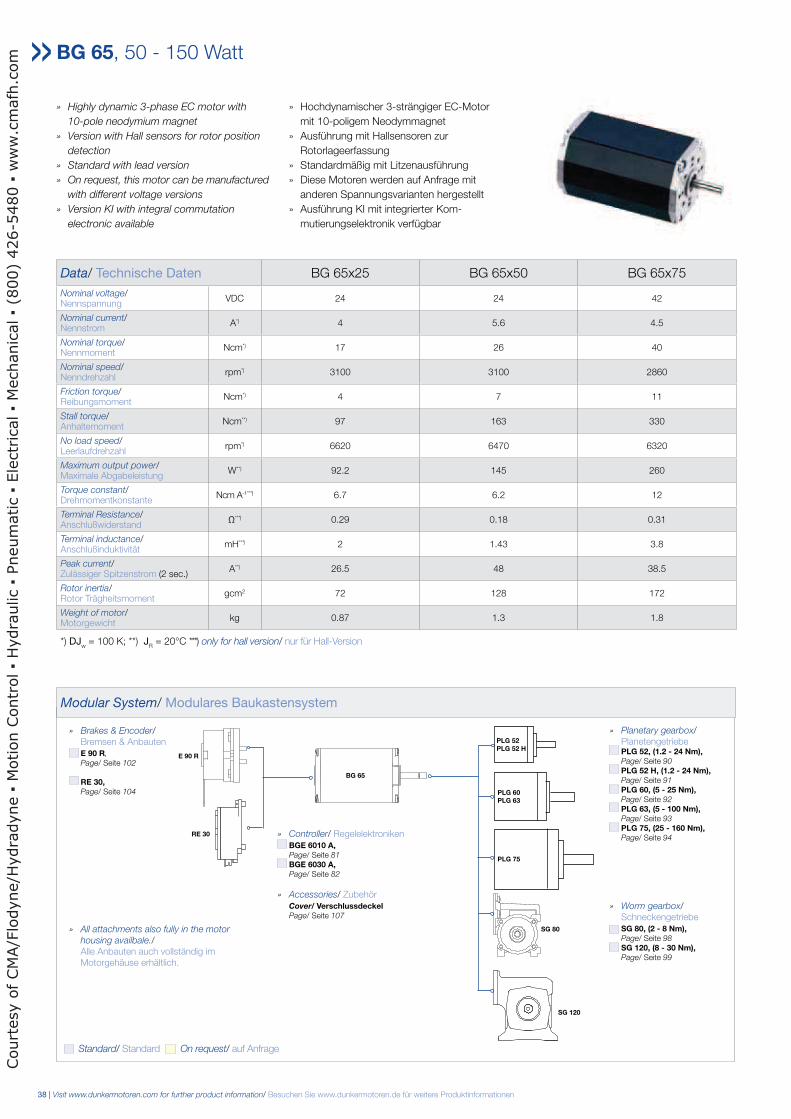
» Highly dynamic 3-phase EC motor with
10-pole neodymium magnet
» Version with Hall sensors for rotor position
detection
» Standard with lead version
» On request, this motor can be manufactured
with different voltage versions
» Version KI with integral commutation
electronic available
» Hochdynamischer 3-strängiger EC-Motor mit 10-poligem Neodymmagnet» Ausführung mit Hallsensoren zur Rotorlageerfassung» Standardmäßig mit Litzenausführung» Diese Motoren werden auf Anfrage mit anderen Spannungsvarianten hergestellt » Ausführung KI mit integrierter Kom- mutierungselektronik verfügbar
Data/ Technische Daten BG 65x25 BG 65x50 BG 65x75
Nominal voltage/Nennspannung
VDC 24 24 42
Nominal current/Nennstrom
A*) 4 5.6 4.5
Nominal torque/Nennmoment
Ncm*) 17 26 40
Nominal speed/Nenndrehzahl
rpm*) 3100 3100 2860
Friction torque/Reibungsmoment
Ncm*) 4 7 11
Stall torque/Anhaltemoment
Ncm**) 97 163 330
No load speed/Leerlaufdrehzahl
rpm*) 6620 6470 6320
Maximum output power/Maximale Abgabeleistung
W**) 92.2 145 260
Torque constant/Drehmomentkonstante
Ncm A-1* * *) 6.7 6.2 12
Terminal Resistance/Anschlußwiderstand
Ω* * *) 0.29 0.18 0.31
Terminal inductance/Anschlußinduktivität
mH* * *) 2 1.43 3.8
Peak current/Zulässiger Spitzenstrom (2 sec.)
A**) 26.5 48 38.5
Rotor inertia/Rotor Trägheitsmoment
gcm2 72 128 172
Weight of motor/Motorgewicht
kg 0.87 1.3 1.8
*) DJw = 100 K; **) J
R = 20°C ***) only for hall version/ nur für Hall-Version
BG 65, 50 - 150 Watt
Modular System/ Modulares Baukastensystem
» Planetary gearbox/ Planetengetriebe PLG 52, (1.2 - 24 Nm), Page/ Seite 90
PLG 52 H, (1.2 - 24 Nm), Page/ Seite 91
PLG 60, (5 - 25 Nm), Page/ Seite 92
PLG 63, (5 - 100 Nm), Page/ Seite 93
PLG 75, (25 - 160 Nm), Page/ Seite 94
» Worm gearbox/ Schneckengetriebe SG 80, (2 - 8 Nm), Page/ Seite 98
SG 120, (8 - 30 Nm), Page/ Seite 99
» Brakes & Encoder/ Bremsen & Anbauten E 90 R,
Page/ Seite 102
RE 30, Page/ Seite 104
» Controller/ Regelelektroniken BGE 6010 A, Page/ Seite 81
BGE 6030 A, Page/ Seite 82
» Accessories/ Zubehör Cover/ Verschlussdeckel Page/ Seite 107
PLG 52 PLG 52 H
PLG 60 PLG 63
PLG 75
SG 80
SG 120
RE 30
E 90 R
BG 65
Standard/ Standard On request/ auf Anfrage
» All attachments also fully in the motor
housing availbale./ Alle Anbauten auch vollständig im Motorgehäuse erhältlich.
Court
esy o
f CM
A/F
lodyne/H
ydra
dyne
Motion C
ontr
ol
Hydra
ulic
Pneum
atic
Ele
ctr
ical
Mechanic
al
(800)
426-5
480
ww
w.c
mafh
.com
Visit www.dunkermotoren.com for further product information/ Besuchen Sie www.dunkermotoren.de für weitere Produktinformationen | 39
0 10 20 30 40 50 60 70 80 90 100 Ncm
7000
6000
5000
4000
3000
2000
1000
0
70
60
50
40
30
20
10
0
35
30
25
20
15
10
5
0 rate
d sp
eed/
Dreh
zahl
n(r
pm)
effic
ienc
y/W
irkun
gsgr
adη
(%
)
curr
ent/
Stro
mI (
A)
N = f (M)
J = f (M)
MN
η
0 20 40 60 80 100 120 140 160 180 200 Ncm
7000
6000
5000
4000
3000
2000
1000
0
70
60
50
40
30
20
10
0
35
30
25
20
15
10
5
0 rate
d sp
eed/
Dreh
zahl
n(r
pm)
effic
ienc
y/W
irkun
gsgr
adη
(%
)
curr
ent/
Stro
mI (
A)
N = f (M)J = f (M)
MN
η
0 30 60 90 120 150 180 210 240 270 300 Ncm
7000
6000
5000
4000
3000
2000
1000
0
70
60
50
40
30
20
10
0
70
60
50
40
30
20
10
0 rate
d sp
eed/
Dreh
zahl
n(r
pm)
effic
ienc
y/W
irkun
gsgr
adη
(%
)
curr
ent/
Stro
mI(
A)
MN
N = f (M)
J = f (M)
η
ϑR = 20°C
ΔϑW = 100K
ϑR = 20°C
ΔϑW = 100K
ϑR = 20°C
ΔϑW = 100K
BG 65x50, 24V
BG 65x75, 42V
BG 65x25, 24V
!= KI
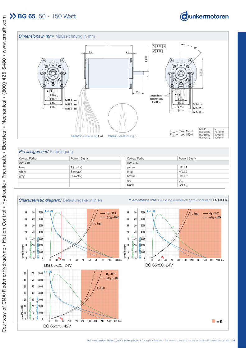
Pin assignment/ Pinbelegung
Colour/ Farbe Power | Signal Colour/ Farbe Power | Signal
AWG 18 AWG 26
blue A (motor) yellow HALL1
white B (motor) green HALL2
grey C (motor) brown HALL3
red UHall
black GNDHall
Dimensions in mm/ Maßzeichnung in mm
BG 65x50, 24V
45°
Ø 48 ±0.1
A
Ø 25 -0.04
Ø 36 ±0.1
Ø 40 ±0.1
Ø 48 ±0.1
4x M4 7 -1 mm
4x M5 7 -1 mm
4x M5 7 -1 mm
2 -0.3
L
2 -0.3
25 ±1
Anschlusslitzen/
Connection Leads
L = 300 ±30
-0.0
05
0.06 A
0.03
Ø 8
-0.0
11
65±
0.5
4x Ø 3. 7 -0.11
4x Ø 4.66 -0.11
4x Ø 4.66 -0.11
Ø 40 ±0.1
Ø 36 ±0.1
B
Ø 25 -0.04
BG 65x25, 24V
Motor LBG 65x25 75 ±0.8BG 65x50 100±0.8BG 65x75 125±0.8
BG 65x75, 42V
BG 65, 50 - 150 Watt
Faxial
= max. 150NF
radial = max. 150N
!= KI
4x M4 7-1 mm
4x M5 7-1 mm
4x M5 7-1 mm
Version/ Ausführung KIVersion/ Ausführung Hall
Characteristic diagram/ Belastungskennlinien In accordance with/ Belastungskennlinien gezeichnet nach EN 60034
Court
esy o
f CM
A/F
lodyne/H
ydra
dyne
Motion C
ontr
ol
Hydra
ulic
Pneum
atic
Ele
ctr
ical
Mechanic
al
(800)
426-5
480
ww
w.c
mafh
.com
40 | Visit www.dunkermotoren.com for further product information/ Besuchen Sie www.dunkermotoren.de für weitere Produktinformationen
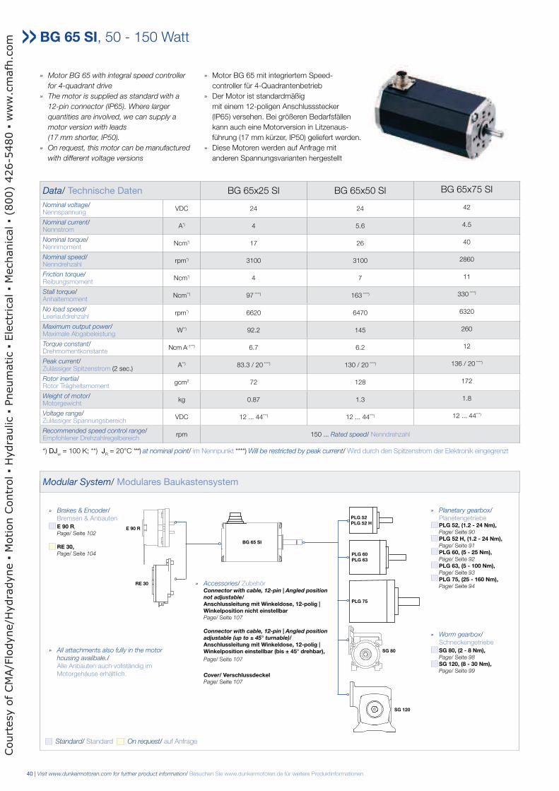
» Motor BG 65 with integral speed controller
for 4-quadrant drive
» The motor is supplied as standard with a
12-pin connector (IP65). Where larger
quantities are involved, we can supply a
motor version with leads
(17 mm shorter, IP50).
» On request, this motor can be manufactured
with different voltage versions
» Motor BG 65 mit integriertem Speed- controller für 4-Quadrantenbetrieb» Der Motor ist standardmäßig mit einem 12-poligen Anschlussstecker (IP65) versehen. Bei größeren Bedarfsfällen kann auch eine Motorversion in Litzenaus- führung (17 mm kürzer, IP50) geliefert werden. » Diese Motoren werden auf Anfrage mit anderen Spannungsvarianten hergestellt
Data/ Technische Daten BG 65x25 SI BG 65x50 SI BG 65x75 SI
Nominal voltage/Nennspannung
VDC 24 24 42
Nominal current/Nennstrom
A*) 4 5.6 4.5
Nominal torque/Nennmoment
Ncm*) 17 26 40
Nominal speed/Nenndrehzahl
rpm*) 3100 3100 2860
Friction torque/Reibungsmoment
Ncm*) 4 7 11
Stall torque/Anhaltemoment
Ncm**) 97 ****) 163 ****) 330 ****)
No load speed/Leerlaufdrehzahl
rpm*) 6620 6470 6320
Maximum output power/Maximale Abgabeleistung
W**) 92.2 145 260
Torque constant/Drehmomentkonstante
Ncm A-1* * *) 6.7 6.2 12
Peak current/Zulässiger Spitzenstrom (2 sec.)
A**) 83.3 / 20 ****) 130 / 20 ****) 136 / 20 ****)
Rotor inertia/Rotor Trägheitsmoment
gcm2 72 128 172
Weight of motor/Motorgewicht
kg 0.87 1.3 1.8
Voltage range/Zulässiger Spannungsbereich
VDC 12 ... 44***) 12 ... 44***) 12 ... 44***)
Recommended speed control range/Empfohlener Drehzahlregelbereich
rpm 150 ... Rated speed/ Nenndrehzahl
*) DJw = 100 K; **) J
R = 20°C ***) at nominal point/ im Nennpunkt ****) Will be restricted by peak current/ Wird durch den Spitzenstrom der Elektronik eingegrenzt
BG 65 SI, 50 - 150 Watt
Modular System/ Modulares Baukastensystem
» Planetary gearbox/ Planetengetriebe PLG 52, (1.2 - 24 Nm), Page/ Seite 90
PLG 52 H, (1.2 - 24 Nm), Page/ Seite 91
PLG 60, (5 - 25 Nm), Page/ Seite 92
PLG 63, (5 - 100 Nm), Page/ Seite 93
PLG 75, (25 - 160 Nm), Page/ Seite 94
» Worm gearbox/ Schneckengetriebe SG 80, (2 - 8 Nm), Page/ Seite 98
SG 120, (8 - 30 Nm), Page/ Seite 99
» Brakes & Encoder/ Bremsen & Anbauten E 90 R,
Page/ Seite 102
RE 30, Page/ Seite 104
» Accessories/ Zubehör Connector with cable, 12-pin | Angled position not adjustable/ Anschlussleitung mit Winkeldose, 12-polig | Winkelposition nicht einstellbar Page/ Seite 107
Connector with cable, 12-pin | Angled position adjustable (up to ± 45° turnable)/ Anschlussleitung mit Winkeldose, 12-polig | Winkelposition einstellbar (bis ± 45° drehbar),
Page/ Seite 107 Cover/ Verschlussdeckel Page/ Seite 107
PLG 52 PLG 52 H
PLG 60 PLG 63
PLG 75
SG 80
SG 120
RE 30
E 90 R
BG 65 SI
Standard/ Standard On request/ auf Anfrage
» All attachments also fully in the motor
housing availbale./ Alle Anbauten auch vollständig im Motorgehäuse erhältlich.
Court
esy o
f CM
A/F
lodyne/H
ydra
dyne
Motion C
ontr
ol
Hydra
ulic
Pneum
atic
Ele
ctr
ical
Mechanic
al
(800)
426-5
480
ww
w.c
mafh
.com
Visit www.dunkermotoren.com for further product information/ Besuchen Sie www.dunkermotoren.de für weitere Produktinformationen | 41
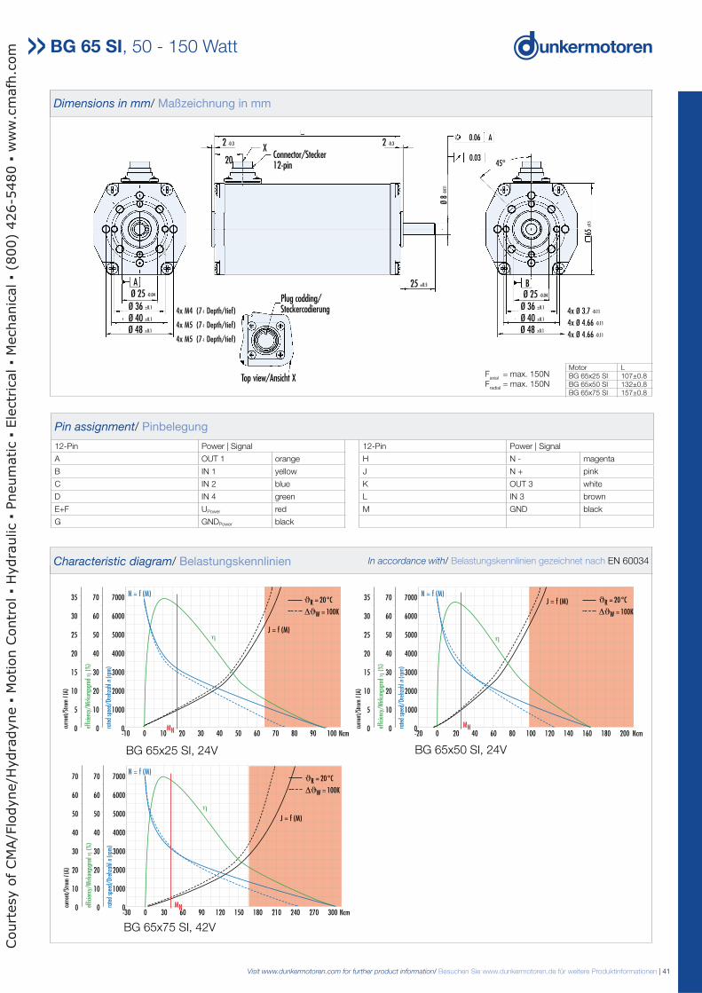
Pin assignment/ Pinbelegung
12-Pin Power | Signal 12-Pin Power | Signal
A OUT 1 orange H N - magenta
B IN 1 yellow J N + pink
C IN 2 blue K OUT 3 white
D IN 4 green L IN 3 brown
E+F UPower red M GND black
G GNDPower black
-10 0 10 20 30 40 50 60 70 80 90 100 Ncm
7000
6000
5000
4000
3000
2000
1000
0
70
60
50
40
30
20
10
0
35
30
25
20
15
10
5
0 rate
d sp
eed/
Dreh
zahl
n(r
pm)
effic
ienc
y/W
irkun
gsgr
adη
(%
)
curr
ent/
Stro
mI(
A)
N = f (M)
J = f (M)
MN
η
-20 0 20 40 60 80 100 120 140 160 180 200 Ncm
7000
6000
5000
4000
3000
2000
1000
0
70
60
50
40
30
20
10
0
35
30
25
20
15
10
5
0 rate
d sp
eed/
Dreh
zahl
n(r
pm)
effic
ienc
y/W
irkun
gsgr
adη
(%
)
curr
ent/
Stro
mI(
A)
N = f (M)J = f (M)
MN
η
ϑR = 20°C
∆ϑW = 100K
ϑR = 20°C
∆ϑW = 100K
BG 65x50 SI, 24VBG 65x25 SI, 24V
Dimensions in mm/ Maßzeichnung in mm
BG 65x50 SI, 24V
20
-0.0
05
Ø 40 ±0.1
Ø 48 ±0.1
Ø 36 ±0.1
AØ 25 -0.04
4x M4 (7-1 Depth/tief)
4x M5 (7-1 Depth/tief)
4x M5 (7-1 Depth/tief)
Top view/Ansicht X
Plug codding/Steckercodierung
25 ±0.5
Ø 48 ±0.1
Ø 40 ±0.1
Ø 36 ±0.1
B
Ø 8
-0.0
11
0.06 A
0.0345°
65±0
.5
4x Ø 3.7 -0.11
4x Ø 4.66 -0.11
4x Ø 4.66 -0.11
Ø 25 -0.04
2 -0.3X
Connector/Stecker12-pin
2 -0.3
BG 65x25 SI, 24V
Motor LBG 65x25 SI 107±0.8BG 65x50 SI 132±0.8BG 65x75 SI 157±0.8
BG 65x75 SI, 42V
BG 65 SI, 50 - 150 Watt
Faxial
= max. 150NF
radial = max. 150N
-30 0 30 60 90 120 150 180 210 240 270 300 Ncm
7000
6000
5000
4000
3000
2000
1000
0
70
60
50
40
30
20
10
0
70
60
50
40
30
20
10
0 rate
d sp
eed/
Dreh
zahl
n(r
pm)
effic
ienc
y/W
irkun
gsgr
adη
(%
)
curr
ent/
Stro
mI(
A)
MN
N = f (M)
J = f (M)
η
ϑR = 20°C
∆ϑW = 100K
Characteristic diagram/ Belastungskennlinien In accordance with/ Belastungskennlinien gezeichnet nach EN 60034
Court
esy o
f CM
A/F
lodyne/H
ydra
dyne
Motion C
ontr
ol
Hydra
ulic
Pneum
atic
Ele
ctr
ical
Mechanic
al
(800)
426-5
480
ww
w.c
mafh
.com
42 | Visit www.dunkermotoren.com for further product information/ Besuchen Sie www.dunkermotoren.de für weitere Produktinformationen
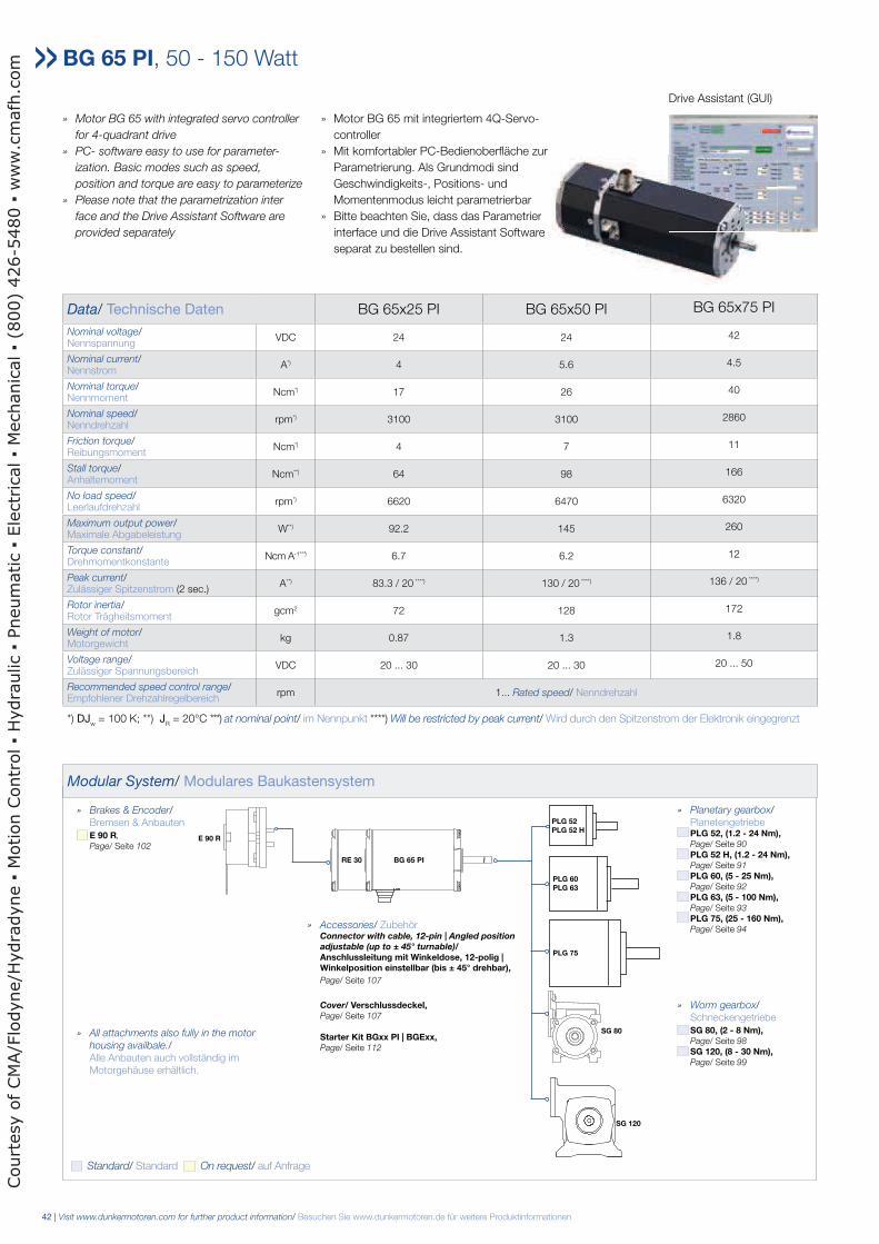
» Motor BG 65 with integrated servo controller
for 4-quadrant drive
» PC- software easy to use for parameter-
ization. Basic modes such as speed,
position and torque are easy to parameterize
» Please note that the parametrization inter
face and the Drive Assistant Software are
provided separately
» Motor BG 65 mit integriertem 4Q-Servo-
controller
» Mit komfortabler PC-Bedienoberfläche zur
Parametrierung. Als Grundmodi sind
Geschwindigkeits-, Positions- und
Momentenmodus leicht parametrierbar
» Bitte beachten Sie, dass das Parametrier
interface und die Drive Assistant Software
separat zu bestellen sind.
Data/ Technische Daten BG 65x25 PI BG 65x50 PI BG 65x75 PI
Nominal voltage/Nennspannung
VDC 24 24 42
Nominal current/Nennstrom
A*) 4 5.6 4.5
Nominal torque/Nennmoment
Ncm*) 17 26 40
Nominal speed/Nenndrehzahl
rpm*) 3100 3100 2860
Friction torque/Reibungsmoment
Ncm*) 4 7 11
Stall torque/Anhaltemoment
Ncm**) 64 98 166
No load speed/Leerlaufdrehzahl
rpm*) 6620 6470 6320
Maximum output power/Maximale Abgabeleistung
W**) 92.2 145 260
Torque constant/Drehmomentkonstante
Ncm A-1* * *) 6.7 6.2 12
Peak current/Zulässiger Spitzenstrom (2 sec.)
A**) 83.3 / 20 ****) 130 / 20 ****) 136 / 20 ****)
Rotor inertia/Rotor Trägheitsmoment
gcm2 72 128 172
Weight of motor/Motorgewicht
kg 0.87 1.3 1.8
Voltage range/Zulässiger Spannungsbereich
VDC 20 ... 30 20 ... 30 20 ... 50
Recommended speed control range/Empfohlener Drehzahlregelbereich
rpm 1... Rated speed/ Nenndrehzahl
*) DJw = 100 K; **) J
R = 20°C ***) at nominal point/ im Nennpunkt ****) Will be restricted by peak current/ Wird durch den Spitzenstrom der Elektronik eingegrenzt
BG 65 PI, 50 - 150 Watt
Modular System/ Modulares Baukastensystem
zur
rier
are
Drive Assistant (GUI)
» Planetary gearbox/ Planetengetriebe PLG 52, (1.2 - 24 Nm), Page/ Seite 90
PLG 52 H, (1.2 - 24 Nm), Page/ Seite 91
PLG 60, (5 - 25 Nm), Page/ Seite 92
PLG 63, (5 - 100 Nm), Page/ Seite 93
PLG 75, (25 - 160 Nm), Page/ Seite 94
» Worm gearbox/ Schneckengetriebe SG 80, (2 - 8 Nm), Page/ Seite 98
SG 120, (8 - 30 Nm), Page/ Seite 99
» Brakes & Encoder/ Bremsen & Anbauten E 90 R,
Page/ Seite 102
» Accessories/ Zubehör Connector with cable, 12-pin | Angled position adjustable (up to ± 45° turnable)/ Anschlussleitung mit Winkeldose, 12-polig | Winkelposition einstellbar (bis ± 45° drehbar),
Page/ Seite 107 Cover/ Verschlussdeckel, Page/ Seite 107
Starter Kit BGxx PI | BGExx, Page/ Seite 112
PLG 52 PLG 52 H
PLG 60 PLG 63
PLG 75
SG 80
SG 120
E 90 R
BG 65 PI
Standard/ Standard On request/ auf Anfrage
» All attachments also fully in the motor
housing availbale./ Alle Anbauten auch vollständig im Motorgehäuse erhältlich.
RE 30
Court
esy o
f CM
A/F
lodyne/H
ydra
dyne
Motion C
ontr
ol
Hydra
ulic
Pneum
atic
Ele
ctr
ical
Mechanic
al
(800)
426-5
480
ww
w.c
mafh
.com

Visit www.dunkermotoren.com for further product information/ Besuchen Sie www.dunkermotoren.de für weitere Produktinformationen | 43
A
4x M4 7-1 mm
4x M5 7-1 mm
4x M5 7-1 mm
4x Ø 3.7 -0.11
4x Ø 4.66 -0.11
4x Ø 4.66 -0.11
Ø 25 -0.04
2 -0.3
452 -0.3
L
20Ø 36 ±0.1
Ø 40 ±0.1
Ø 48 ±0.1
B
Ø 25 -0.04
25 ±1
Ø 40 ±0.1
Ø 48 ±0.1
0.06
0.03 45°
A
Ø 8
-0.0
11
65±0
.5
-0.0
05
Ø 36 ±0.1
Connector/Stecker12-pin
Connector/Stecker5-pin
Dimensions in mm/ Maßzeichnung in mm
BG 65x50 PI, 24VBG 65x25 PI, 24V
Motor LBG 65x25 PI 160±0.3BG 65x50 PI 185±0.3BG 65x75 PI 210±0.3
BG 65x75 PI, 42V
BG 65 PI, 50 - 150 Watt
Faxial
= max. 150NF
radial = max. 150N
Pin assignment/ Pinbelegung
12-Pin Power | Signal 12-Pin Power | Signal 5-Pin Service
A OUT 1 orange G + M GNDPower
black 1 n.c.
B IN 0 yellow H IN 4 / AI - magenta 2 n.c.
C IN 1 blue J IN 3 / AI + pink 3 n.c.
D ULogic
green K OUT 2 white 4 PC
E + F UPower
red L IN 2 brown 5 PC
Characteristic diagram/ Belastungskennlinien In accordance with/ Belastungskennlinien gezeichnet nach EN 60034
-10 0 10 20 30 40 50 60 70 80 90 100 Ncm
7000
6000
5000
4000
3000
2000
1000
0
70
60
50
40
30
20
10
0
35
30
25
20
15
10
5
0 rate
d sp
eed/
Dreh
zahl
n(r
pm)
effic
ienc
y/W
irkun
gsgr
adη
(%
)
curr
ent/
Stro
mI(
A)
N = f (M)
J = f (M)
MN
η
-20 0 20 40 60 80 100 120 140 160 180 200 Ncm
7000
6000
5000
4000
3000
2000
1000
0
70
60
50
40
30
20
10
0
35
30
25
20
15
10
5
0 rate
d sp
eed/
Dreh
zahl
n(r
pm)
effic
ienc
y/W
irkun
gsgr
adη
(%
)
curr
ent/
Stro
mI(
A)
N = f (M)J = f (M)
MN
η
ϑR = 20°C
∆ϑW = 100K
ϑR = 20°C
∆ϑW = 100K
-30 0 30 60 90 120 150 180 210 240 270 300 Ncm
7000
6000
5000
4000
3000
2000
1000
0
70
60
50
40
30
20
10
0
70
60
50
40
30
20
10
0 rate
d sp
eed/
Dreh
zahl
n(r
pm)
effic
ienc
y/W
irkun
gsgr
adη
(%
)
curr
ent/
Stro
mI(
A)
MN
N = f (M)
J = f (M)
η
ϑR = 20°C
∆ϑW = 100K
Court
esy o
f CM
A/F
lodyne/H
ydra
dyne
Motion C
ontr
ol
Hydra
ulic
Pneum
atic
Ele
ctr
ical
Mechanic
al
(800)
426-5
480
ww
w.c
mafh
.com
44 | Visit www.dunkermotoren.com for further product information/ Besuchen Sie www.dunkermotoren.de für weitere Produktinformationen
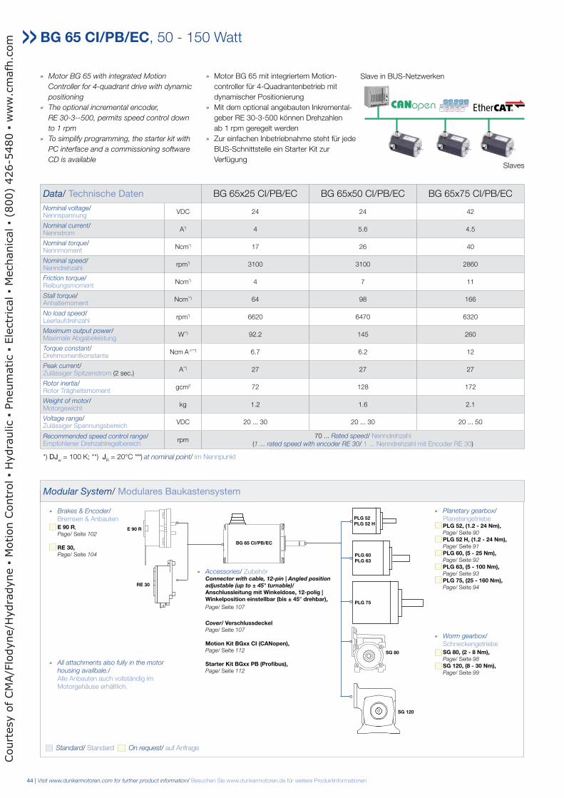
» Motor BG 65 with integrated Motion
Controller for 4-quadrant drive with dynamic
positioning
» The optional incremental encoder,
RE 30-3--500, permits speed control down
to 1 rpm
» To simplify programming, the starter kit with
PC interface and a commissioning software
CD is available
» Motor BG 65 mit integriertem Motion-
controller für 4-Quadrantenbetrieb mit
dynamischer Positionierung
» Mit dem optional angebauten Inkremental-
geber RE 30-3-500 können Drehzahlen
ab 1 rpm geregelt werden
» Zur einfachen Inbetriebnahme steht für jede
BUS-Schnittstelle ein Starter Kit zur
Verfügung
Data/ Technische Daten BG 65x25 CI/PB/EC BG 65x50 CI/PB/EC BG 65x75 CI/PB/EC
Nominal voltage/Nennspannung
VDC 24 24 42
Nominal current/Nennstrom
A*) 4 5.6 4.5
Nominal torque/Nennmoment
Ncm*) 17 26 40
Nominal speed/Nenndrehzahl
rpm*) 3100 3100 2860
Friction torque/Reibungsmoment
Ncm*) 4 7 11
Stall torque/Anhaltemoment
Ncm**) 64 98 166
No load speed/Leerlaufdrehzahl
rpm*) 6620 6470 6320
Maximum output power/Maximale Abgabeleistung
W**) 92.2 145 260
Torque constant/Drehmomentkonstante
Ncm A-1* * *) 6.7 6.2 12
Peak current/Zulässiger Spitzenstrom (2 sec.)
A**) 27 27 27
Rotor inertia/Rotor Trägheitsmoment
gcm2 72 128 172
Weight of motor/Motorgewicht
kg 1.2 1.6 2.1
Voltage range/Zulässiger Spannungsbereich
VDC 20 ... 30 20 ... 30 20 ... 50
Recommended speed control range/Empfohlener Drehzahlregelbereich
rpm70 ... Rated speed/ Nenndrehzahl
(1 ... rated speed with encoder RE 30/ 1 ... Nenndrehzahl mit Encoder RE 30)
*) DJw = 100 K; **) J
R = 20°C ***) at nominal point/ im Nennpunkt
BG 65 CI/PB/EC, 50 - 150 Watt
Modular System/ Modulares Baukastensystem
Slave in BUS-Netzwerken
Slaves
» Planetary gearbox/ Planetengetriebe PLG 52, (1.2 - 24 Nm), Page/ Seite 90
PLG 52 H, (1.2 - 24 Nm), Page/ Seite 91
PLG 60, (5 - 25 Nm), Page/ Seite 92
PLG 63, (5 - 100 Nm), Page/ Seite 93
PLG 75, (25 - 160 Nm), Page/ Seite 94
» Worm gearbox/ Schneckengetriebe SG 80, (2 - 8 Nm), Page/ Seite 98
SG 120, (8 - 30 Nm), Page/ Seite 99
» Brakes & Encoder/ Bremsen & Anbauten E 90 R,
Page/ Seite 102
RE 30, Page/ Seite 104
» Accessories/ Zubehör Connector with cable, 12-pin | Angled position adjustable (up to ± 45° turnable)/ Anschlussleitung mit Winkeldose, 12-polig | Winkelposition einstellbar (bis ± 45° drehbar),
Page/ Seite 107 Cover/ Verschlussdeckel Page/ Seite 107
Motion Kit BGxx CI (CANopen), Page/ Seite 112
Starter Kit BGxx PB (Profibus), Page/ Seite 112
PLG 52 PLG 52 H
PLG 60 PLG 63
PLG 75
SG 80
SG 120
RE 30
E 90 R
BG 65 CI/PB/EC
Standard/ Standard On request/ auf Anfrage
» All attachments also fully in the motor
housing availbale./ Alle Anbauten auch vollständig im Motorgehäuse erhältlich.
Court
esy o
f CM
A/F
lodyne/H
ydra
dyne
Motion C
ontr
ol
Hydra
ulic
Pneum
atic
Ele
ctr
ical
Mechanic
al
(800)
426-5
480
ww
w.c
mafh
.com
Visit www.dunkermotoren.com for further product information/ Besuchen Sie www.dunkermotoren.de für weitere Produktinformationen | 45
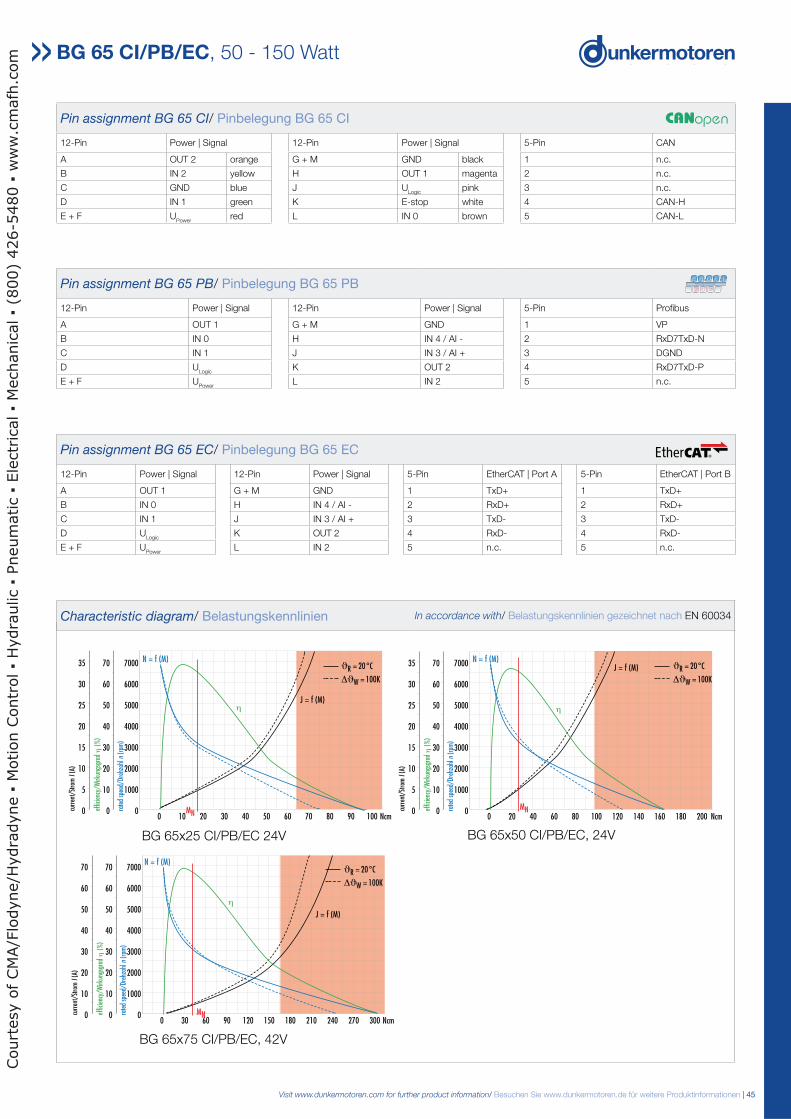
BG 65x50 CI/PB/EC, 24VBG 65x25 CI/PB/EC 24V
BG 65x75 CI/PB/EC, 42V
BG 65 CI/PB/EC, 50 - 150 Watt
Characteristic diagram/ Belastungskennlinien In accordance with/ Belastungskennlinien gezeichnet nach EN 60034
Pin assignment BG 65 CI/ Pinbelegung BG 65 CI
12-Pin Power | Signal 12-Pin Power | Signal 5-Pin CAN
A OUT 2 orange G + M GND black 1 n.c.
B IN 2 yellow H OUT 1 magenta 2 n.c.
C GND blue J ULogic
pink 3 n.c.
D IN 1 green K E-stop white 4 CAN-H
E + F UPower
red L IN 0 brown 5 CAN-L
Pin assignment BG 65 PB/ Pinbelegung BG 65 PB
12-Pin Power | Signal 12-Pin Power | Signal 5-Pin Profibus
A OUT 1 G + M GND 1 VP
B IN 0 H IN 4 / AI - 2 RxD7TxD-N
C IN 1 J IN 3 / AI + 3 DGND
D ULogic
K OUT 2 4 RxD7TxD-P
E + F UPower
L IN 2 5 n.c.
Pin assignment BG 65 EC/ Pinbelegung BG 65 EC
12-Pin Power | Signal 12-Pin Power | Signal 5-Pin EtherCAT | Port A 5-Pin EtherCAT | Port B
A OUT 1 G + M GND 1 TxD+ 1 TxD+
B IN 0 H IN 4 / AI - 2 RxD+ 2 RxD+
C IN 1 J IN 3 / AI + 3 TxD- 3 TxD-
D ULogic
K OUT 2 4 RxD- 4 RxD-
E + F UPower
L IN 2 5 n.c. 5 n.c.
0 10 20 30 40 50 60 70 80 90 100 Ncm
7000
6000
5000
4000
3000
2000
1000
0
70
60
50
40
30
20
10
0
35
30
25
20
15
10
5
0 rate
d sp
eed/
Dreh
zahl
n(r
pm)
effic
ienc
y/W
irkun
gsgr
adη
(%
)
curr
ent/
Stro
mI (
A)
N = f (M)
J = f (M)
MN
η
0 20 40 60 80 100 120 140 160 180 200 Ncm
7000
6000
5000
4000
3000
2000
1000
0
70
60
50
40
30
20
10
0
35
30
25
20
15
10
5
0 rate
d sp
eed/
Dreh
zahl
n(r
pm)
effic
ienc
y/W
irkun
gsgr
adη (
%)
curr
ent/
Stro
mI(
A)
N = f (M)J = f (M)
MN
η
ϑR = 20°C
∆ϑW = 100K
ϑR = 20°C
∆ϑW = 100K
0 30 60 90 120 150 180 210 240 270 300 Ncm
7000
6000
5000
4000
3000
2000
1000
0
70
60
50
40
30
20
10
0
70
60
50
40
30
20
10
0 rate
d sp
eed/
Dreh
zahl
n(r
pm)
effic
ienc
y/W
irkun
gsgr
adη (
%)
curr
ent/
Stro
mI (
A)
MN
N = f (M)
J = f (M)
η
ϑR = 20°C
∆ϑW = 100K
Court
esy o
f CM
A/F
lodyne/H
ydra
dyne
Motion C
ontr
ol
Hydra
ulic
Pneum
atic
Ele
ctr
ical
Mechanic
al
(800)
426-5
480
ww
w.c
mafh
.com
46 | Visit www.dunkermotoren.com for further product information/ Besuchen Sie www.dunkermotoren.de für weitere Produktinformationen
BG 65 CI/PB/EC, 50 - 150 Watt
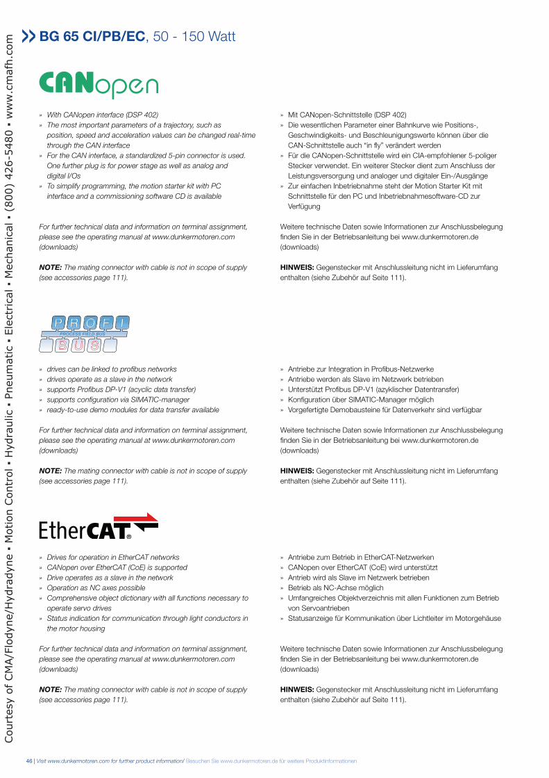
» With CANopen interface (DSP 402)
» The most important parameters of a trajectory, such as
position, speed and acceleration values can be changed real-time
through the CAN interface
» For the CAN interface, a standardized 5-pin connector is used.
One further plug is for power stage as well as analog and
digital I/Os
» To simplify programming, the motion starter kit with PC
interface and a commissioning software CD is available
For further technical data and information on terminal assignment,
please see the operating manual at www.dunkermotoren.com
(downloads)
NOTE: The mating connector with cable is not in scope of supply
(see accessories page 111).
» Mit CANopen-Schnittstelle (DSP 402)» Die wesentlichen Parameter einer Bahnkurve wie Positions-, Geschwindigkeits- und Beschleunigungswerte können über die CAN-Schnittstelle auch “in fly” verändert werden» Für die CANopen-Schnittstelle wird ein CIA-empfohlener 5-poliger Stecker verwendet. Ein weiterer Stecker dient zum Anschluss der Leistungsversorgung und analoger und digitaler Ein-/Ausgänge» Zur einfachen Inbetriebnahme steht der Motion Starter Kit mit Schnittstelle für den PC und Inbetriebnahmesoftware-CD zur Verfügung Weitere technische Daten sowie Informationen zur Anschlussbelegung finden Sie in der Betriebsanleitung bei www.dunkermotoren.de (downloads) HINWEIS: Gegenstecker mit Anschlussleitung nicht im Lieferumfang enthalten (siehe Zubehör auf Seite 111).
» drives can be linked to profibus networks
» drives operate as a slave in the network
» supports Profibus DP-V1 (acyclic data transfer)
» supports configuration via SIMATIC-manager
» ready-to-use demo modules for data transfer available
For further technical data and information on terminal assignment,
please see the operating manual at www.dunkermotoren.com
(downloads)
NOTE: The mating connector with cable is not in scope of supply
(see accessories page 111).
» Antriebe zur Integration in Profibus-Netzwerke» Antriebe werden als Slave im Netzwerk betrieben» Unterstützt Profibus DP-V1 (azyklischer Datentransfer)» Konfiguration über SIMATIC-Manager möglich» Vorgefertigte Demobausteine für Datenverkehr sind verfügbar Weitere technische Daten sowie Informationen zur Anschlussbelegung finden Sie in der Betriebsanleitung bei www.dunkermotoren.de (downloads) HINWEIS: Gegenstecker mit Anschlussleitung nicht im Lieferumfang enthalten (siehe Zubehör auf Seite 111).
» Drives for operation in EtherCAT networks
» CANopen over EtherCAT (CoE) is supported
» Drive operates as a slave in the network
» Operation as NC axes possible
» Comprehensive object dictionary with all functions necessary to
operate servo drives
» Status indication for communication through light conductors in
the motor housing
For further technical data and information on terminal assignment,
please see the operating manual at www.dunkermotoren.com
(downloads)
NOTE: The mating connector with cable is not in scope of supply
(see accessories page 111).
» Antriebe zum Betrieb in EtherCAT-Netzwerken» CANopen over EtherCAT (CoE) wird unterstützt» Antrieb wird als Slave im Netzwerk betrieben» Betrieb als NC-Achse möglich» Umfangreiches Objektverzeichnis mit allen Funktionen zum Betrieb von Servoantrieben» Statusanzeige für Kommunikation über Lichtleiter im Motorgehäuse Weitere technische Daten sowie Informationen zur Anschlussbelegung finden Sie in der Betriebsanleitung bei www.dunkermotoren.de (downloads) HINWEIS: Gegenstecker mit Anschlussleitung nicht im Lieferumfang enthalten (siehe Zubehör auf Seite 111).
Court
esy o
f CM
A/F
lodyne/H
ydra
dyne
Motion C
ontr
ol
Hydra
ulic
Pneum
atic
Ele
ctr
ical
Mechanic
al
(800)
426-5
480
ww
w.c
mafh
.com
Visit www.dunkermotoren.com for further product information/ Besuchen Sie www.dunkermotoren.de für weitere Produktinformationen | 47
BG 65 CI/PB/EC, 50 - 150 Watt
4x Ø 3.7 -0.11
4x Ø 4.66 -0.1
4x Ø 4.66 -0.1
65±0
.5
20
mm
mm
mm
2 -0.3
L
2 -0.3
25 ±1
-0.0
05Ø
8 -0
.011
A0.06
0.03 45°
B
Ø 25 -0.04
Ø 36 ±0.1
Ø 40 ±0.1
Ø 48 ±0.1
Connector/Stecker12-pin
Connector/Stecker5-pin
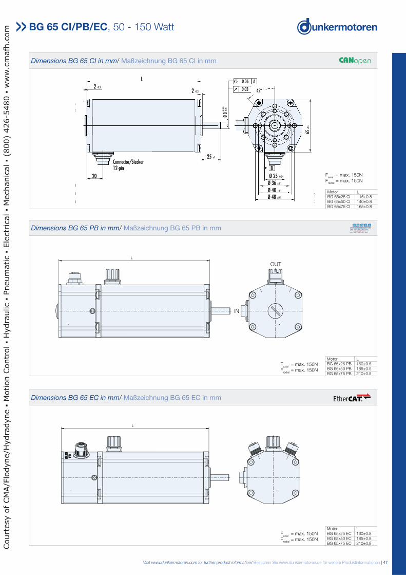
Dimensions BG 65 CI in mm/ Maßzeichnung BG 65 CI in mm
Motor LBG 65x25 CI 115±0.8BG 65x50 CI 140±0.8BG 65x75 CI 165±0.8
Faxial
= max. 150NF
radial = max. 150N
Dimensions BG 65 PB in mm/ Maßzeichnung BG 65 PB in mm
Faxial
= max. 150NF
radial = max. 150N
Dimensions BG 65 EC in mm/ Maßzeichnung BG 65 EC in mm
Motor LBG 65x25 PB 160±0.5BG 65x50 PB 185±0.5BG 65x75 PB 210±0.5
L
Faxial
= max. 150NF
radial = max. 150N
Motor LBG 65x25 EC 160±0.8BG 65x50 EC 185±0.8BG 65x75 EC 210±0.8
L
IN
OUT
Court
esy o
f CM
A/F
lodyne/H
ydra
dyne
Motion C
ontr
ol
Hydra
ulic
Pneum
atic
Ele
ctr
ical
Mechanic
al
(800)
426-5
480
ww
w.c
mafh
.com
48 | Visit www.dunkermotoren.com for further product information/ Besuchen Sie www.dunkermotoren.de für weitere Produktinformationen
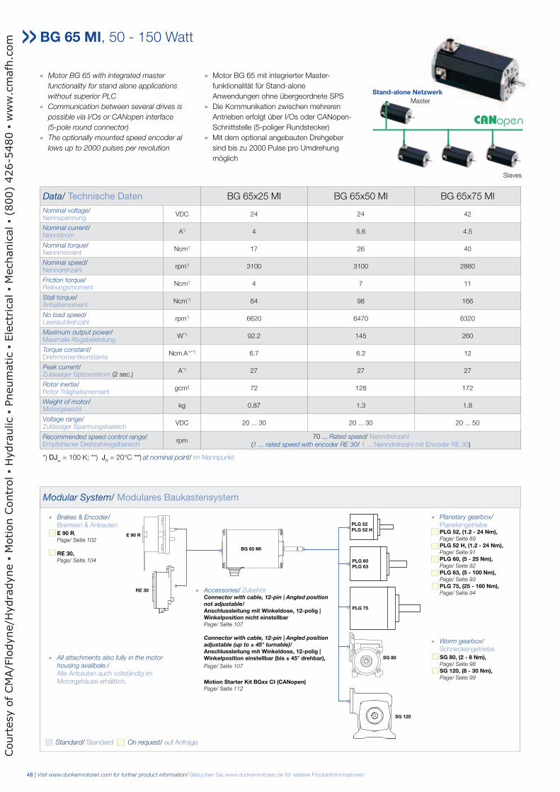
» Motor BG 65 with integrated master
functionality for stand alone applications
without superior PLC
» Communication between several drives is
possible via I/Os or CANopen interface
(5-pole round connector)
» The optionally mounted speed encoder al
lows up to 2000 pulses per revolution
» Motor BG 65 mit integrierter Master-
funktionalität für Stand-alone
Anwendungen ohne übergeordnete SPS
» Die Kommunikation zwischen mehreren
Antrieben erfolgt über I/Os oder CANopen-
Schnittstelle (5-poliger Rundstecker)
» Mit dem optional angebauten Drehgeber
sind bis zu 2000 Pulse pro Umdrehung
möglich
Data/ Technische Daten BG 65x25 MI BG 65x50 MI BG 65x75 MI
Nominal voltage/Nennspannung
VDC 24 24 42
Nominal current/Nennstrom
A*) 4 5.6 4.5
Nominal torque/Nennmoment
Ncm*) 17 26 40
Nominal speed/Nenndrehzahl
rpm*) 3100 3100 2860
Friction torque/Reibungsmoment
Ncm*) 4 7 11
Stall torque/Anhaltemoment
Ncm**) 64 98 166
No load speed/Leerlaufdrehzahl
rpm*) 6620 6470 6320
Maximum output power/Maximale Abgabeleistung
W**) 92.2 145 260
Torque constant/Drehmomentkonstante
Ncm A-1* * *) 6.7 6.2 12
Peak current/Zulässiger Spitzenstrom (2 sec.)
A**) 27 27 27
Rotor inertia/Rotor Trägheitsmoment
gcm2 72 128 172
Weight of motor/Motorgewicht
kg 0.87 1.3 1.8
Voltage range/Zulässiger Spannungsbereich
VDC 20 ... 30 20 ... 30 20 ... 50
Recommended speed control range/Empfohlener Drehzahlregelbereich
rpm70 ... Rated speed/ Nenndrehzahl
(1 ... rated speed with encoder RE 30/ 1 ... Nenndrehzahl mit Encoder RE 30)
*) DJw = 100 K; **) J
R = 20°C ***) at nominal point/ im Nennpunkt
BG 65 MI, 50 - 150 Watt
Modular System/ Modulares Baukastensystem
Stand-alone Netzwerk
Slaves
Master
» Planetary gearbox/ Planetengetriebe PLG 52, (1.2 - 24 Nm), Page/ Seite 89
PLG 52 H, (1.2 - 24 Nm), Page/ Seite 91
PLG 60, (5 - 25 Nm), Page/ Seite 92
PLG 63, (5 - 100 Nm), Page/ Seite 93
PLG 75, (25 - 160 Nm), Page/ Seite 94
» Worm gearbox/ Schneckengetriebe SG 80, (2 - 8 Nm), Page/ Seite 98
SG 120, (8 - 30 Nm), Page/ Seite 99
» Brakes & Encoder/ Bremsen & Anbauten E 90 R,
Page/ Seite 102
RE 30, Page/ Seite 104
» Accessories/ Zubehör Connector with cable, 12-pin | Angled position not adjustable/ Anschlussleitung mit Winkeldose, 12-polig | Winkelposition nicht einstellbar Page/ Seite 107
Connector with cable, 12-pin | Angled position adjustable (up to ± 45° turnable)/ Anschlussleitung mit Winkeldose, 12-polig | Winkelposition einstellbar (bis ± 45° drehbar),
Page/ Seite 107 Motion Starter Kit BGxx CI (CANopen) Page/ Seite 112
PLG 52 PLG 52 H
PLG 60 PLG 63
PLG 75
SG 80
SG 120
RE 30
E 90 R
BG 65 MI
Standard/ Standard On request/ auf Anfrage
» All attachments also fully in the motor
housing availbale./ Alle Anbauten auch vollständig im Motorgehäuse erhältlich.
Court
esy o
f CM
A/F
lodyne/H
ydra
dyne
Motion C
ontr
ol
Hydra
ulic
Pneum
atic
Ele
ctr
ical
Mechanic
al
(800)
426-5
480
ww
w.c
mafh
.com
Visit www.dunkermotoren.com for further product information/ Besuchen Sie www.dunkermotoren.de für weitere Produktinformationen | 49
BG 65x50 MI, 24VBG 65x25 MI, 24V
BG 65x75 MI, 42V
BG 65 MI, 50 - 150 Watt
Characteristic diagram/ Belastungskennlinien In accordance with/ Belastungskennlinien gezeichnet nach EN 60034
A
4x M4 7-1 mm
4x M5 7-1 mm
4x M5 7-1 mm
4x Ø 3.7 -0.11
4x Ø 4.66 -0.11
4x Ø 4.66 -0.11
Ø 25 -0.04
2 -0.3
452 -0.3
L
20Ø 36 ±0.1
Ø 40 ±0.1
Ø 48 ±0.1
B
Ø 25 -0.04
25 ±1
Ø 40 ±0.1
Ø 48 ±0.1
0.06
0.03 45°
A
Ø 8
-0.0
11
65±0
.5
-0.0
05
Ø 36 ±0.1
Connector/Stecker12-pin
Connector/Stecker5-pin
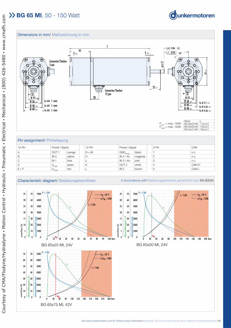
Dimensions in mm/ Maßzeichnung in mm
Motor LBG 65x25 MI 115±0.3BG 65x50 MI 140±0.3BG 65x75 MI 165±0.3
Faxial
= max. 150NF
radial = max. 150N
Pin assignment/ Pinbelegung
12-Pin Power | Signal 12-Pin Power | Signal 5-Pin CAN
A OUT 1 orange G + M GNDPower
black 1 n.c.
B IN 0 yellow H IN 4 / AI- magenta 2 n.c.
C IN 1 blue J IN 3 / AI+ pink 3 n.c.
D ULogic
green K OUT 2 white 4 CAN-H
E + F UPower
red L IN 2 brown 5 CAN-L
0 10 20 30 40 50 60 70 80 90 100 Ncm
7000
6000
5000
4000
3000
2000
1000
0
70
60
50
40
30
20
10
0
35
30
25
20
15
10
5
0 rate
d sp
eed/
Dreh
zahl
n(r
pm)
effic
ienc
y/W
irkun
gsgr
adη
(%
)
curr
ent/
Stro
mI (
A)
N = f (M)
J = f (M)
MN
η
0 20 40 60 80 100 120 140 160 180 200 Ncm
7000
6000
5000
4000
3000
2000
1000
0
70
60
50
40
30
20
10
0
35
30
25
20
15
10
5
0 rate
d sp
eed/
Dreh
zahl
n(r
pm)
effic
ienc
y/W
irkun
gsgr
adη
(%
)
curr
ent/
Stro
mI (
A)
N = f (M)J = f (M)
MN
η
ϑR = 20°C
∆ϑW = 100K
ϑR = 20°C
∆ϑW = 100K
0 30 60 90 120 150 180 210 240 270 300 Ncm
7000
6000
5000
4000
3000
2000
1000
0
70
60
50
40
30
20
10
0
70
60
50
40
30
20
10
0 rate
d sp
eed/
Dreh
zahl
n(r
pm)
effic
ienc
y/W
irkun
gsgr
adη
(%
)
curr
ent/
Stro
mI (
A)
MN
N = f (M)
J = f (M)
η
ϑR = 20°C
∆ϑW = 100K
BG 65x75 CI, 42V
Court
esy o
f CM
A/F
lodyne/H
ydra
dyne
Motion C
ontr
ol
Hydra
ulic
Pneum
atic
Ele
ctr
ical
Mechanic
al
(800)
426-5
480
ww
w.c
mafh
.com
50 | Visit www.dunkermotoren.com for further product information/ Besuchen Sie www.dunkermotoren.de für weitere Produktinformationen
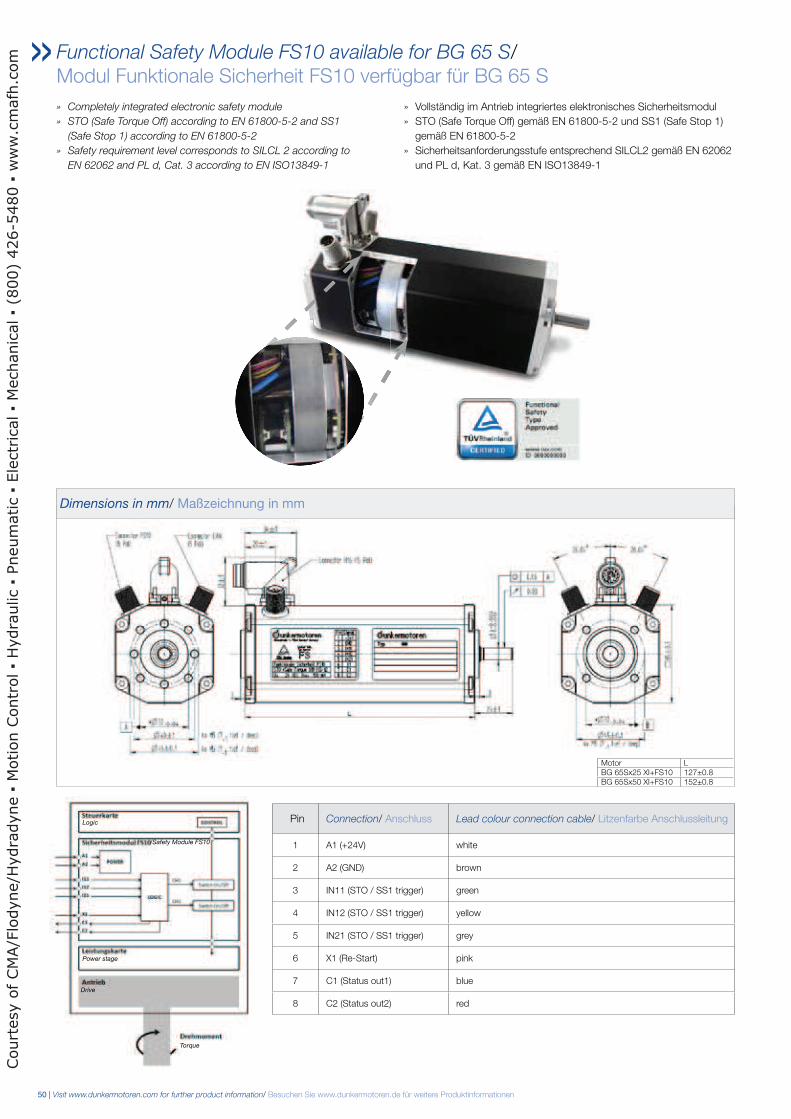
Functional Safety Module FS10 available for BG 65 S/ Modul Funktionale Sicherheit FS10 verfügbar für BG 65 S
» Completely integrated electronic safety module
» STO (Safe Torque Off) according to EN 61800-5-2 and SS1
(Safe Stop 1) according to EN 61800-5-2
» Safety requirement level corresponds to SILCL 2 according to
EN 62062 and PL d, Cat. 3 according to EN ISO13849-1
» Vollständig im Antrieb integriertes elektronisches Sicherheitsmodul
» STO (Safe Torque Off) gemäß EN 61800-5-2 und SS1 (Safe Stop 1)
gemäß EN 61800-5-2
» Sicherheitsanforderungsstufe entsprechend SILCL2 gemäß EN 62062
und PL d, Kat. 3 gemäß EN ISO13849-1
Pin Connection/ Anschluss Lead colour connection cable/ Litzenfarbe Anschlussleitung
1 A1 (+24V) white
2 A2 (GND) brown
3 IN11 (STO / SS1 trigger) green
4 IN12 (STO / SS1 trigger) yellow
5 IN21 (STO / SS1 trigger) grey
6 X1 (Re-Start) pink
7 C1 (Status out1) blue
8 C2 (Status out2) red
Logic
Power stage
Drive
/Safety Module FS10
Torque
Dimensions in mm/ Maßzeichnung in mm
Motor LBG 65Sx25 XI+FS10 127±0.8BG 65Sx50 XI+FS10 152±0.8
Court
esy o
f CM
A/F
lodyne/H
ydra
dyne
Motion C
ontr
ol
Hydra
ulic
Pneum
atic
Ele
ctr
ical
Mechanic
al
(800)
426-5
480
ww
w.c
mafh
.com
Visit www.dunkermotoren.com for further product information/ Besuchen Sie www.dunkermotoren.de für weitere Produktinformationen | 51
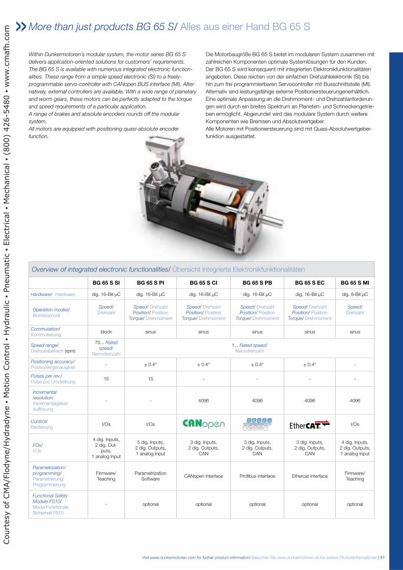
More than just products BG 65 S/ Alles aus einer Hand BG 65 S
Within Dunkermotoren’s modular system, the motor series BG 65 S
delivers application-oriented solutions for customers’ requirements.
The BG 65 S is available with numerous integrated electronic function-
alities. These range from a simple speed electronic (SI) to a freely-
programmable servo-controller with CANopen BUS interface (MI). Alter-
natively, external controllers are available. With a wide range of planetary
and worm gears, these motors can be perfectly adapted to the torque
and speed requirements of a particular application.
A range of brakes and absolute encoders rounds off the modular
system.
All motors are equipped with positioning quasi-absolute encoder
function.
Die Motorbaugröße BG 65 S bietet im modularen System zusammen mit
zahlreichen Komponenten optimale Systemlösungen für den Kunden.
Der BG 65 S wird konsequent mit integrierten Elektronikfunktionalitäten
angeboten. Diese reichen von der einfachen Drehzahlelektronik (SI) bis
hin zum frei programmierbaren Servocontroller mit Busschnittstelle (MI).
Alternativ sind leistungsfähige externe Positioniersteuerungenerhältlich.
Eine optimale Anpassung an die Drehmoment- und Drehzahlanforderun-
gen wird durch ein breites Spektrum an Planeten- und Schneckengetrie-
ben ermöglicht. Abgerundet wird das modulare System durch weitere
Komponenten wie Bremsen und Absolutwertgeber.
Alle Motoren mit Positioniersteuerung sind mit Quasi-Absolutwertgeber-
funktion ausgestattet.
Overview of integrated electronic functionalities/ Übersicht integrierte Elektronikfunktionalitäten
BG 65 S SI BG 65 S PI BG 65 S CI BG 65 S PB BG 65 S EC BG 65 S MI
Hardware/ Hardware dig. 16-Bit µC dig. 16-Bit µC dig. 16-Bit µC dig. 16-Bit µC dig. 16-Bit µC dig. 8-Bit µC
Operation modes/Betriebsmodi
Speed/ Drehzahl
Speed/ Drehzahl Position/ Position
Torque/ Drehmoment
Speed/ Drehzahl Position/ Position
Torque/ Drehmoment
Speed/ Drehzahl Position/ Position
Torque/ Drehmoment
Speed/ Drehzahl Position/ Position
Torque/ Drehmoment
Speed/ Drehzahl
Commutation/ Kommutierung
block sinus sinus sinus sinus sinus
Speed range/Drehzahlbereich (rpm)
70... Rated
speed/ Nenndrehzahl
1... Rated speed/ Nenndrehzahl
Positioning accuracy/Positioniergenauigkeit
- ± 0.4° ± 0.4° ± 0.4° ± 0.4° -
Pulses per rev./Pulse pro Umdrehung
15 15 - - - -
Incremental
resolution/Inkrementalgeber Auflösung
- - 4096 4096 4096 4096
Control/Bedienung
I/Os I/Os I/Os
I/Os/I/Os
4 dig. Inputs, 2 dig. Out-
puts, 1 analog Input
5 dig. Inputs, 2 dig. Outputs, 1 analog Input
3 dig. Inputs, 2 dig. Outputs,
CAN
3 dig. Inputs, 2 dig. Outputs,
CAN
3 dig. Inputs, 2 dig. Outputs,
CAN
4 dig. Inputs, 2 dig. Outputs, 1 analog Input
Parametrization/
programming/Parametrierung/ Programmierung
Firmware/ Teaching
Parametrization Software
CANopen interface Profibus interface Ethercat interfaceFirmware/ Teaching
Functional Safety
Module FS10/Modul Funktionale Sicherheit FS10
- optional optional optional optional optional
Court
esy o
f CM
A/F
lodyne/H
ydra
dyne
Motion C
ontr
ol
Hydra
ulic
Pneum
atic
Ele
ctr
ical
Mechanic
al
(800)
426-5
480
ww
w.c
mafh
.com
52 | Visit www.dunkermotoren.com for further product information/ Besuchen Sie www.dunkermotoren.de für weitere Produktinformationen
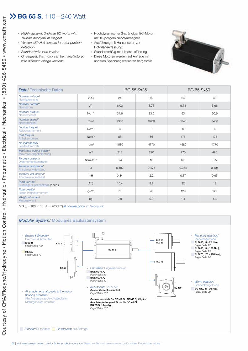
Data/ Technische Daten BG 65 Sx25 BG 65 Sx50
Nominal voltage/Nennspannung
VDC 24 40 24 40
Nominal current/Nennstrom
A*) 6.02 3.76 9.54 5.96
Nominal torque/Nennmoment
Ncm*) 34.6 33.6 53 50.9
Nominal speed/Nenndrehzahl
rpm*) 2980 3200 3240 3480
Friction torque/Reibungsmoment
Ncm*) 3 3 6 6
Stall torque/Anhaltemoment
Ncm**) 86 86 175 175
No load speed/Leerlaufdrehzahl
rpm*) 4580 4770 4580 4770
Maximum output power/Maximale Abgabeleistung
W**) 218 220 470 470
Torque constant/Drehmomentkonstante
Ncm A-1* * *) 6.4 10 6.3 8.5
Terminal resistance/Anschlusswiderstand
Ω 0.192 0.478 0.084 0.194
Terminal inductance/Anschlussinduktivität
mH 0.84 2.2 0.37 0.95
Peak current/Zulässiger Spitzenstrom (2 sec.)
A**) 16.4 9.8 32 19
Rotor inertia/Rotor Trägheitsmoment
gcm2 70 70 129 129
Weight of motor/Motorgewicht
kg 0.9 0.9 1.4 1.4
*) DJw = 100 K; **) J
R = 20°C ***) at nominal point/ im Nennpunkt
BG 65 S, 110 - 240 Watt
Modular System/ Modulares Baukastensystem
» Planetary gearbox/ Planetengetriebe PLG 60, (5 - 25 Nm), Page/ Seite 92
PLG 63, (5 - 100 Nm), Page/ Seite 93
PLG 75, (25 - 160 Nm), Page/ Seite 94
» Worm gearbox/ Schneckengetriebe SG 120, (8 - 30 Nm), Page/ Seite 99
» Brakes & Encoder/ Bremsen & Anbauten E 90 R,
Page/ Seite 102
RE 56, Page/ Seite 104
» Controller/ Regelelektroniken BGE 6010 A, Page/ Seite 81
BGE 6030 A, Page/ Seite 82
» Accessories/ Zubehör Cover/ Verschlussdeckel, Page/ Seite 107 Connector cable for BG 45 SI | BG 65 S, 15-pin/ Anschlussleitung mit Dose für BG 45 SI | BG 65 S, 15-polig, Page/ Seite 107
PLG 75
SG 120
RE 56
E 90 R
BG 65 S
PLG 60 PLG 63
Standard/ Standard On request/ auf Anfrage
» All attachments also fully in the motor
housing availbale./ Alle Anbauten auch vollständig im Motorgehäuse erhältlich.
» Highly dynamic 3-phase EC motor with
10-pole neodymium magnet
» Version with Hall sensors for rotor position
detection
» Standard with lead version
» On request, this motor can be manufactured
with different voltage versions
» Hochdynamischer 3-strängiger EC-Motor
mit 10-poligem Neodymmagnet
» Ausführung mit Hallsensoren zur
Rotorlageerfassung
» Standardmäßig mit Litzenausführung
» Diese Motoren werden auf Anfrage mit
anderen Spannungsvarianten hergestellt
Court
esy o
f CM
A/F
lodyne/H
ydra
dyne
Motion C
ontr
ol
Hydra
ulic
Pneum
atic
Ele
ctr
ical
Mechanic
al
(800)
426-5
480
ww
w.c
mafh
.com
Visit www.dunkermotoren.com for further product information/ Besuchen Sie www.dunkermotoren.de für weitere Produktinformationen | 53
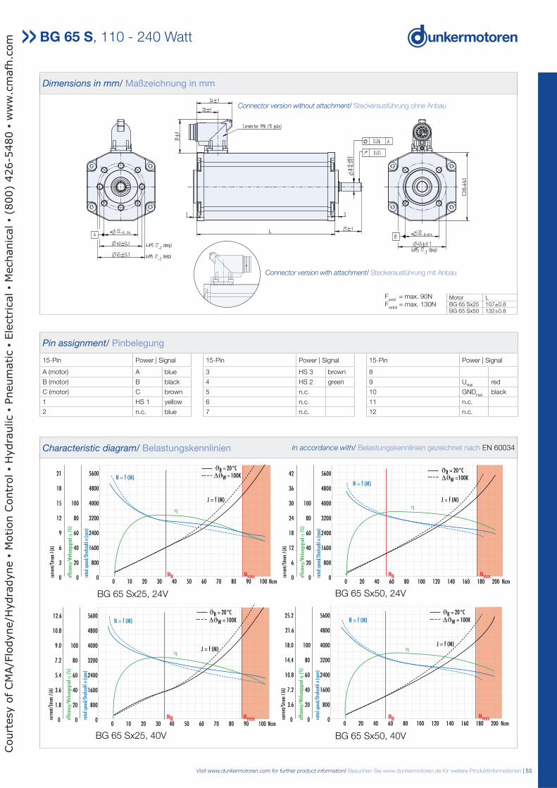
Pin assignment/ Pinbelegung
15-Pin Power | Signal 15-Pin Power | Signal 15-Pin Power | Signal
A (motor) A blue 3 HS 3 brown 8
B (motor) B black 4 HS 2 green 9 UHall
red
C (motor) C brown 5 n.c. 10 GNDHall
black
1 HS 1 yellow 6 n.c. 11 n.c.
2 n.c. blue 7 n.c. 12 n.c.
Dimensions in mm/ Maßzeichnung in mm
Motor LBG 65 Sx25 107±0.8BG 65 Sx50 132±0.8
BG 65 S, 110 - 240 Watt
Faxial
= max. 90NF
radial = max. 130N
BG 65 Sx50, 24VBG 65 Sx25, 24V
BG 65 Sx25, 40V BG 65 Sx50, 40V
Characteristic diagram/ Belastungskennlinien In accordance with/ Belastungskennlinien gezeichnet nach EN 60034
BG 65Sx25, 24 V BG 65Sx50, 24 V
0 10 20 30 40 50 60 70 80 90 100 Ncm
5600
4800
4000
3200
2400
1600
800
0
100
80
60
40
20
0
21
18
15
12
9
6
3
0 rate
d sp
eed/
Dreh
zahl
n(r
pm)
effic
ienc
y/W
irkun
gsgr
adη
(%
)
curr
ent/
Stro
mI(
A)
N = f (M)
J = f (M)
MN
η
0 20 40 60 80 100 120 140 160 180 200 Ncm
5600
4800
4000
3200
2400
1600
800
0
100
80
60
40
20
0
42
36
30
24
18
12
6
0 rate
d sp
eed/
Dreh
zahl
n(r
pm)
effic
ienc
y/W
irkun
gsgr
adη
(%
)
curr
ent/
Stro
mI(
A)
N = f (M)
J = f (M)
MN
η
Mmax
R = 20°CϑΔϑW = 100K
Mmax
ϑR = 20°CΔϑW =100K
0 10 20 30 40 50 60 70 80 90 100 Ncm
5600
4800
4000
3200
2400
1600
800
0
100
80
60
40
20
0
12.6
10.8
9.0
7.2
5.4
3.6
1.8
0 rate
d sp
eed/
Dreh
zahl
n(r
pm)
effic
ienc
y/W
irkun
gsgr
adη
(%
)
curr
ent/
Stro
mI(
A)
MN
N = f (M)
J = f (M)η
0 20 40 60 80 100 120 140 160 180 200 Ncm
5600
4800
4000
3200
2400
1600
800
0
100
80
60
40
20
0
25.2
21.6
18.0
14.4
10.8
7.2
3.6
0 rate
d sp
eed/
Dreh
zahl
n(r
pm)
effic
ienc
y/W
irkun
gsgr
adη
(%
)
curr
ent/
Stro
mI(
A)
N = f (M)
J = f (M)
MN
η
Mmax
ϑR = 20°CΔϑW = 100K
Mmax
ϑR = 20°CΔϑW = 100K
Connector version without attachment/ Steckerausführung ohne Anbau
Connector version with attachment/ Steckerausführung mit Anbau
L
Court
esy o
f CM
A/F
lodyne/H
ydra
dyne
Motion C
ontr
ol
Hydra
ulic
Pneum
atic
Ele
ctr
ical
Mechanic
al
(800)
426-5
480
ww
w.c
mafh
.com
54 | Visit www.dunkermotoren.com for further product information/ Besuchen Sie www.dunkermotoren.de für weitere Produktinformationen
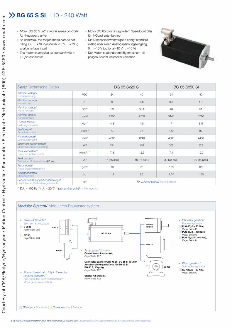
» Motor BG 65 S with integral speed controller
for 4-quadrant drive
» As standard, the target speed can be set
using a 0 ... +10 V (optional -10 V ... +10 V)
analog voltage input
» The motor is supplied as standard with a
15-pin connector.
» Motor BG 65 S mit integriertem Speedcontroller
für 4-Quadrantenbetrieb
» Die Drehzahlsollwertvorgabe erfolgt standard-
mäßig über einen Analogspannungseingang
0 ... +10 V (optional -10 V ... +10 V)
» Der Motor ist standardmäßig mit einem 15-
poligen Anschlussstecker versehen.
Data/ Technische Daten BG 65 Sx25 SI BG 65 Sx50 SI
Nominal voltage/Nennspannung
VDC 24 40 24 40
Nominal current/Nennstrom
A*) 6 3.6 8.3 5.4
Nominal torque/Nennmoment
Ncm*) 38 38.1 48 51
Nominal speed/Nenndrehzahl
rpm*) 2700 2700 3140 3210
Friction torque/Reibungsmoment
Ncm*) 4.3 4.5 7 8.5
Stall torque/Anhaltemoment
Ncm**) 77 78 152 152
No load speed/Leerlaufdrehzahl
rpm*) 4080 4240 4300 4400
Maximum output power/Maximale Abgabeleistung
W**) 154 169 302 327
Torque constant/Drehmomentkonstante
Ncm A-1* * *) 7.8 12.5 7.4 12.3
Peak current/Zulässiger Spitzenstrom (60 sec.)
A**) 16 (75 sec.) 10 (77 sec.) 32 (78 sec.) 20 (86 sec.)
Rotor inertia/Rotor Trägheitsmoment
gcm2 70 70 129 129
Weight of motor/Motorgewicht
kg 1.2 1.2 1.65 1.65
Recommended speed control range/Empfohlener Drehzahlregelbereich
rpm 70 ... Rated speed/ Nenndrehzahl
*) DJw = 100 K; **) J
R = 20°C ***) at nominal point/ im Nennpunkt
BG 65 S SI, 110 - 240 Watt
Modular System/ Modulares Baukastensystem
» Planetary gearbox/ Planetengetriebe PLG 60, (5 - 25 Nm), Page/ Seite 92
PLG 63, (5 - 100 Nm), Page/ Seite 93
PLG 75, (25 - 160 Nm), Page/ Seite 94
» Worm gearbox/ Schneckengetriebe SG 120, (8 - 30 Nm), Page/ Seite 99
» Brakes & Encoder/ Bremsen & Anbauten E 90 R,
Page/ Seite 102
RE 56, Page/ Seite 104
» Accessories/ Zubehör Cover/ Verschlussdeckel, Page/ Seite 107 Connector cable for BG 45 SI | BG 65 S, 15-pin/ Anschlussleitung mit Dose für BG 45 SI | BG 65 S, 15-polig, Page/ Seite 107
Starter Kit BGxx SI, Page/ Seite 112
PLG 75
SG 120
RE 56
E 90 R
BG 65 S SI
PLG 60 PLG 63
Standard/ Standard On request/ auf Anfrage
» All attachments also fully in the motor
housing availbale./ Alle Anbauten auch vollständig im Motorgehäuse erhältlich.
Court
esy o
f CM
A/F
lodyne/H
ydra
dyne
Motion C
ontr
ol
Hydra
ulic
Pneum
atic
Ele
ctr
ical
Mechanic
al
(800)
426-5
480
ww
w.c
mafh
.com
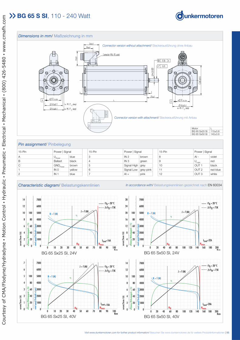
Visit www.dunkermotoren.com for further product information/ Besuchen Sie www.dunkermotoren.de für weitere Produktinformationen | 55
BG 65Sx50 SI, 24 VBG 65Sx25 SI, 24 V
0 10 20 30 40 50 60 70 80 90 100Ncm
7000
6000
5000
4000
3000
2000
1000
0
100
80
60
40
20
0
14
12
10
8
6
4
2
0 rate
d sp
eed/
Dreh
zahl
n(r
pm)
effic
ienc
y/W
irkun
gsgr
adη
(%
)
curr
ent/
Stro
mI(
A)
MN
η η
0 20 40 60 80 100 120 140 160 180 200Ncm
7000
6000
5000
4000
3000
2000
1000
0
100
80
60
40
20
0
28
24
20
16
12
8
4
0 rate
d sp
eed/
Dreh
zahl
n(r
pm)
effic
ienc
y/W
irkun
gsgr
adη
(%
)
curr
ent/
Stro
mI(
A)
MN MmaxMmax
ϑR = 20°C
ΔϑEl = 75K
ϑR = 20°C
ΔϑEl = 75K
ILimit=16A ILimit=32A
J = f (M)J = f (M)N = f (M) N = f (M)
Pin assignment/ Pinbelegung
15-Pin Power | Signal 15-Pin Power | Signal 15-Pin Power | Signal
A UPower
blue 3 IN 2 brown 8 AI - violet
B Ballast black 4 IN 3 green 9 ULogic
red
C GNDPower
brown 5 Signal High grey 10 OUT 1 black
1 IN 0 yellow 6 Signal Low grey-pink 11 OUT 2 red-blue
2 IN 1 blue 7 AI + pink 12 OUT 3 white
Dimensions in mm/ Maßzeichnung in mm
Motor LBG 65 Sx25 SI 115±0.8BG 65 Sx50 SI 140±0.8
BG 65Sx25 SI, 24 V
η
0 10 20 30 40 50 60 70 80 90 100Ncm
7000
6000
5000
4000
3000
2000
1000
0
100
80
60
40
20
0
7
6
5
4
3
2
1
0 rate
d sp
eed/
Dreh
zahl
n(r
pm)
effic
ienc
y/W
irkun
gsgr
adη
(%
)
curr
ent/
Stro
mI(
A)
MN Mmax
ϑR = 20°C
ΔϑEl = 75K
ILimit=10A
J = f (M)
N = f (M)
BG 65Sx50 SI, 40 V
0 20 40 60 80 100 120 140 160 180 200Ncm
7000
6000
5000
4000
3000
2000
1000
0
100
80
60
40
20
0
14
12
10
8
6
4
2
0 rate
d sp
eed/
Dreh
zahl
n (r
pm)
effic
ienc
y/W
irkun
gsgr
ad η
(%
)
curr
ent/
Stro
m I
(A)
MN
N = f (M)
J = f (M)
η
W
Mmax
ϑR = 20°C
Δϑ = 75K
ILimit=20A
BG 65 S SI, 110 - 240 Watt
BG 65 Sx50 SI, 24VBG 65 Sx25 SI, 24V
BG 65 Sx25 SI, 40V BG 65 Sx50 SI, 40V
Characteristic diagram/ Belastungskennlinien In accordance with/ Belastungskennlinien gezeichnet nach EN 60034
Connector version without attachment/ Steckerausführung ohne Anbau
Connector version with attachment/ Steckerausführung mit Anbau
L
Court
esy o
f CM
A/F
lodyne/H
ydra
dyne
Motion C
ontr
ol
Hydra
ulic
Pneum
atic
Ele
ctr
ical
Mechanic
al
(800)
426-5
480
ww
w.c
mafh
.com
56 | Visit www.dunkermotoren.com for further product information/ Besuchen Sie www.dunkermotoren.de für weitere Produktinformationen
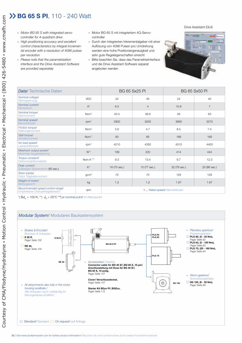
» Motor BG 65 S with integrated servo
controller for 4-quadrant drive
» High positioning accuracy and excellent
control characteristics by integral incremen-
tal encoder with a resolution of 4096 pulses
per revolution
» Please note that the parametrization
interface and the Drive Assistant Software
are provided separately
» Motor BG 65 S mit integriertem 4Q-Servo-
controller
» Durch den integrierten Inkrementalgeber mit einer
Auflösung von 4096 Pulsen pro Umdrehung
werden eine hohe Positioniergenauigkeit und
sehr gute Regeleigenschaften erreicht
» Bitte beachten Sie, dass das Parametrierinterface
und die Drive Assistant Software separat
angeboten werden
Data/ Technische Daten BG 65 Sx25 PI BG 65 Sx50 PI
Nominal voltage/Nennspannung
VDC 24 40 24 40
Nominal current/Nennstrom
A*) 6.5 4 10.8 7
Nominal torque/Nennmoment
Ncm*) 40.5 38.8 56 63
Nominal speed/Nenndrehzahl
rpm*) 2900 3200 3660 3570
Friction torque/Reibungsmoment
Ncm*) 5.6 4.7 8.5 7.4
Stall torque/Anhaltemoment
Ncm**) 83 85 168 169
No load speed/Leerlaufdrehzahl
rpm*) 4210 4350 4310 4400
Maximum output power/Maximale Abgabeleistung
W**) 199 220 414 444
Torque constant/Drehmomentkonstante
Ncm A-1* * *) 8.3 13.4 6.7 12.3
Peak current/Zulässiger Spitzenstrom (60 sec.)
A**) 16 (75 sec.) 10 (77 sec.) 32 (78 sec.) 20 (86 sec.)
Rotor inertia/Rotor Trägheitsmoment
gcm2 70 70 129 129
Weight of motor/Motorgewicht
kg 1.2 1.2 1.67 1.67
Recommended speed control range/Empfohlener Drehzahlregelbereich
rpm 1 ... Rated speed/ Nenndrehzahl
*) DJw = 100 K; **) J
R = 20°C ***) at nominal point/ im Nennpunkt
BG 65 S PI, 110 - 240 Watt
Modular System/ Modulares Baukastensystem
Drive Assistant (GUI)
» Planetary gearbox/ Planetengetriebe PLG 60, (5 - 25 Nm), Page/ Seite 92
PLG 63, (5 - 100 Nm), Page/ Seite 93
PLG 75, (25 - 160 Nm), Page/ Seite 94
» Worm gearbox/ Schneckengetriebe SG 120, (8 - 30 Nm), Page/ Seite 99
» Brakes & Encoder/ Bremsen & Anbauten E 90 R,
Page/ Seite 102
RE 30, Page/ Seite 104
» Accessories/ Zubehör Connector cable for BG 45 SI | BG 65 S, 15-pin/ Anschlussleitung mit Dose für BG 45 SI | BG 65 S, 15-polig, Page/ Seite 107
Cover/ Verschlussdeckel, Page/ Seite 107
Starter Kit BGxx PI | BGExx, Page/ Seite 112
PLG 75
SG 120
RE 30
E 90 R
BG 65 S PI
PLG 60 PLG 63
Standard/ Standard On request/ auf Anfrage
» All attachments also fully in the motor
housing availbale./ Alle Anbauten auch vollständig im Motorgehäuse erhältlich.
Court
esy o
f CM
A/F
lodyne/H
ydra
dyne
Motion C
ontr
ol
Hydra
ulic
Pneum
atic
Ele
ctr
ical
Mechanic
al
(800)
426-5
480
ww
w.c
mafh
.com
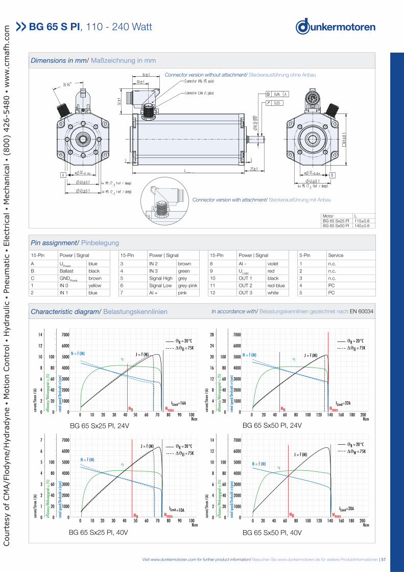
Visit www.dunkermotoren.com for further product information/ Besuchen Sie www.dunkermotoren.de für weitere Produktinformationen | 57
0 10 20 30 40 50 60 70 80 90 100Ncm
7000
6000
5000
4000
3000
2000
1000
0
100
80
60
40
20
0
14
12
10
8
6
4
2
0 rate
d sp
eed/
Dreh
zahl
n(r
pm)
effic
ienc
y/W
irkun
gsgr
adη
(%
)
curr
ent/
Stro
mI(
A)
MN
η η
0 20 40 60 80 100 120 140 160 180 200Ncm
7000
6000
5000
4000
3000
2000
1000
0
100
80
60
40
20
0
28
24
20
16
12
8
4
0 rate
d sp
eed/
Dreh
zahl
n(r
pm)
effic
ienc
y/W
irkun
gsgr
adη
(%
)
curr
ent/
Stro
mI(
A)
MN MmaxMmax
ϑR = 20°C
ΔϑEl = 75K
ϑR = 20°C
ΔϑEl = 75K
ILimit=16A ILimit=32A
J = f (M)J = f (M)N = f (M) N = f (M)
BG 65Sx50 PI, 24 VBG 65Sx25 PI, 24 V
Pin assignment/ Pinbelegung
15-Pin Power | Signal 15-Pin Power | Signal 15-Pin Power | Signal 5-Pin Service
A UPower
blue 3 IN 2 brown 8 AI - violet 1 n.c.
B Ballast black 4 IN 3 green 9 ULogic
red 2 n.c.
C GNDPower
brown 5 Signal High grey 10 OUT 1 black 3 n.c.
1 IN 0 yellow 6 Signal Low grey-pink 11 OUT 2 red-blue 4 PC
2 IN 1 blue 7 AI + pink 12 OUT 3 white 5 PC
Dimensions in mm/ Maßzeichnung in mm
Motor LBG 65 Sx25 PI 115±0.8BG 65 Sx50 PI 140±0.8
η
0 10 20 30 40 50 60 70 80 90 100Ncm
7000
6000
5000
4000
3000
2000
1000
0
100
80
60
40
20
0
7
6
5
4
3
2
1
0 rate
d sp
eed/
Dreh
zahl
n(r
pm)
effic
ienc
y/W
irkun
gsgr
adη
(%
)
curr
ent/
Stro
mI(
A)
MN Mmax
ϑR = 20°C
ΔϑEl = 75K
ILimit=10A
J = f (M)
N = f (M)
0 20 40 60 80 100 120 140 160 180 200Ncm
7000
6000
5000
4000
3000
2000
1000
0
100
80
60
40
20
0
14
12
10
8
6
4
2
0 rate
d sp
eed/
Dreh
zahl
n (r
pm)
effic
ienc
y/W
irkun
gsgr
ad η
(%
)
curr
ent/
Stro
m I
(A)
MN
N = f (M)
J = f (M)
η
W
Mmax
ϑR = 20°C
Δϑ = 75K
ILimit=20A
BG 65Sx25 PI, 40 V BG 65Sx50 PI, 40 V
BG 65 S PI, 110 - 240 Watt
BG 65 Sx50 PI, 24VBG 65 Sx25 PI, 24V
BG 65 Sx25 PI, 40V BG 65 Sx50 PI, 40V
Characteristic diagram/ Belastungskennlinien In accordance with/ Belastungskennlinien gezeichnet nach EN 60034
Connector version without attachment/ Steckerausführung ohne Anbau
Connector version with attachment/ Steckerausführung mit Anbau
L
Court
esy o
f CM
A/F
lodyne/H
ydra
dyne
Motion C
ontr
ol
Hydra
ulic
Pneum
atic
Ele
ctr
ical
Mechanic
al
(800)
426-5
480
ww
w.c
mafh
.com
58 | Visit www.dunkermotoren.com for further product information/ Besuchen Sie www.dunkermotoren.de für weitere Produktinformationen
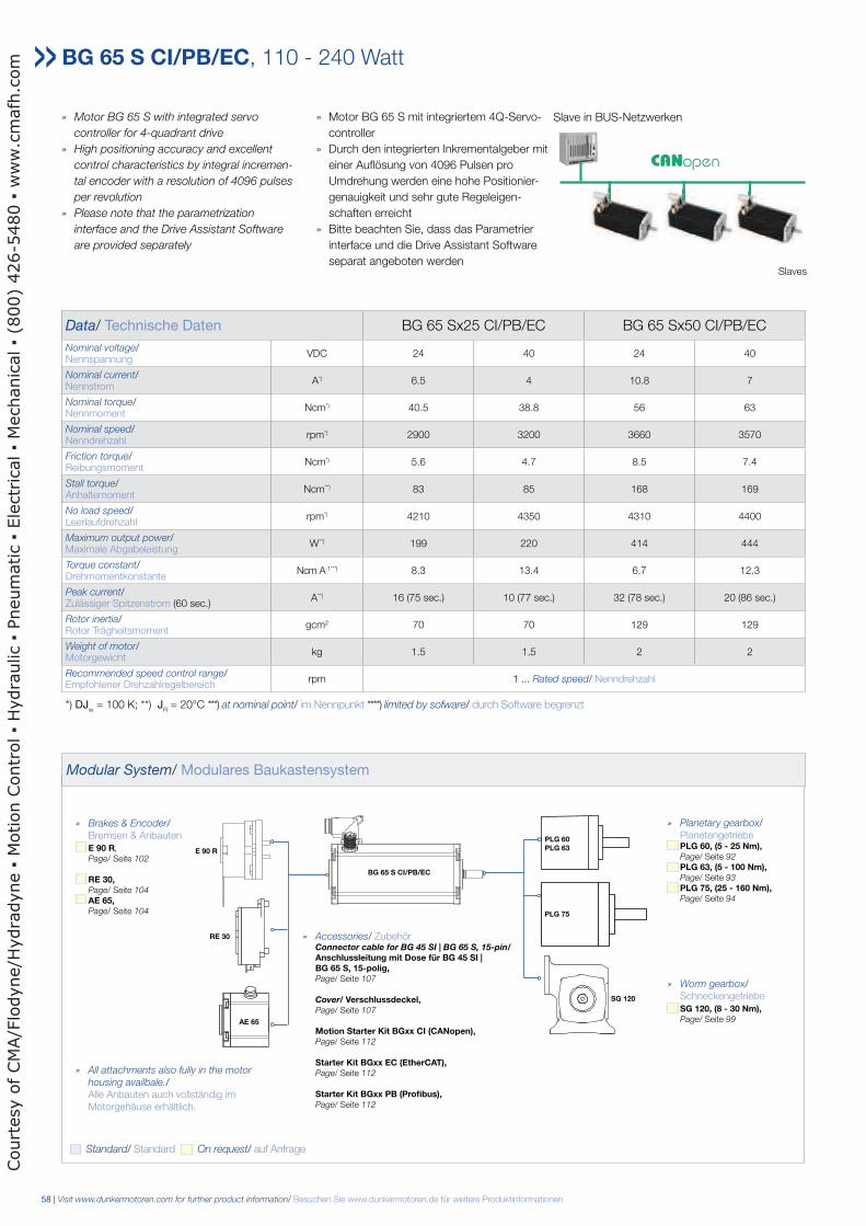
BG 65 S CI/PB/EC, 110 - 240 Watt
» Motor BG 65 S with integrated servo
controller for 4-quadrant drive
» High positioning accuracy and excellent
control characteristics by integral incremen-
tal encoder with a resolution of 4096 pulses
per revolution
» Please note that the parametrization
interface and the Drive Assistant Software
are provided separately
» Motor BG 65 S mit integriertem 4Q-Servo-
controller
» Durch den integrierten Inkrementalgeber mit
einer Auflösung von 4096 Pulsen pro
Umdrehung werden eine hohe Positionier-
genauigkeit und sehr gute Regeleigen-
schaften erreicht
» Bitte beachten Sie, dass das Parametrier
interface und die Drive Assistant Software
separat angeboten werden
Data/ Technische Daten BG 65 Sx25 CI/PB/EC BG 65 Sx50 CI/PB/EC
Nominal voltage/Nennspannung
VDC 24 40 24 40
Nominal current/Nennstrom
A*) 6.5 4 10.8 7
Nominal torque/Nennmoment
Ncm*) 40.5 38.8 56 63
Nominal speed/Nenndrehzahl
rpm*) 2900 3200 3660 3570
Friction torque/Reibungsmoment
Ncm*) 5.6 4.7 8.5 7.4
Stall torque/Anhaltemoment
Ncm**) 83 85 168 169
No load speed/Leerlaufdrehzahl
rpm*) 4210 4350 4310 4400
Maximum output power/Maximale Abgabeleistung
W**) 199 220 414 444
Torque constant/Drehmomentkonstante
Ncm A-1* * *) 8.3 13.4 6.7 12.3
Peak current/Zulässiger Spitzenstrom (60 sec.)
A**) 16 (75 sec.) 10 (77 sec.) 32 (78 sec.) 20 (86 sec.)
Rotor inertia/Rotor Trägheitsmoment
gcm2 70 70 129 129
Weight of motor/Motorgewicht
kg 1.5 1.5 2 2
Recommended speed control range/Empfohlener Drehzahlregelbereich
rpm 1 ... Rated speed/ Nenndrehzahl
*) DJw = 100 K; **) J
R = 20°C ***) at nominal point/ im Nennpunkt ****) limited by sofware/ durch Software begrenzt
Modular System/ Modulares Baukastensystem
Slave in BUS-Netzwerken
» Planetary gearbox/ Planetengetriebe PLG 60, (5 - 25 Nm), Page/ Seite 92
PLG 63, (5 - 100 Nm), Page/ Seite 93
PLG 75, (25 - 160 Nm), Page/ Seite 94
» Worm gearbox/ Schneckengetriebe SG 120, (8 - 30 Nm), Page/ Seite 99
» Brakes & Encoder/ Bremsen & Anbauten E 90 R,
Page/ Seite 102
RE 30, Page/ Seite 104
AE 65, Page/ Seite 104
» Accessories/ Zubehör Connector cable for BG 45 SI | BG 65 S, 15-pin/ Anschlussleitung mit Dose für BG 45 SI | BG 65 S, 15-polig, Page/ Seite 107
Cover/ Verschlussdeckel, Page/ Seite 107
Motion Starter Kit BGxx CI (CANopen), Page/ Seite 112
Starter Kit BGxx EC (EtherCAT), Page/ Seite 112
Starter Kit BGxx PB (Profibus), Page/ Seite 112
PLG 75
SG 120
RE 30
E 90 R
BG 65 S CI/PB/EC
PLG 60 PLG 63
Standard/ Standard On request/ auf Anfrage
» All attachments also fully in the motor
housing availbale./ Alle Anbauten auch vollständig im Motorgehäuse erhältlich.
Slaves
AE 65
Court
esy o
f CM
A/F
lodyne/H
ydra
dyne
Motion C
ontr
ol
Hydra
ulic
Pneum
atic
Ele
ctr
ical
Mechanic
al
(800)
426-5
480
ww
w.c
mafh
.com
Visit www.dunkermotoren.com for further product information/ Besuchen Sie www.dunkermotoren.de für weitere Produktinformationen | 59
BG 65 S CI/PB/EC, 110 - 240 Watt
0 10 20 30 40 50 60 70 80 90 100Ncm
7000
6000
5000
4000
3000
2000
1000
0
100
80
60
40
20
0
14
12
10
8
6
4
2
0 rate
d sp
eed/
Dreh
zahl
n(r
pm)
effic
ienc
y/W
irkun
gsgr
adη
(%
)
curr
ent/
Stro
mI(
A)
MN
η η
0 20 40 60 80 100 120 140 160 180 200Ncm
7000
6000
5000
4000
3000
2000
1000
0
100
80
60
40
20
0
28
24
20
16
12
8
4
0 rate
d sp
eed/
Dreh
zahl
n(r
pm)
effic
ienc
y/W
irkun
gsgr
adη
(%
)
curr
ent/
Stro
mI(
A)
MN MmaxMmax
ϑR = 20°C
ΔϑEl = 75K
ϑR = 20°C
ΔϑEl = 75K
ILimit=16A ILimit=32A
J = f (M)J = f (M)N = f (M) N = f (M)
BG 65Sx50 CI, 24 VBG 65Sx25 CI, 24 V
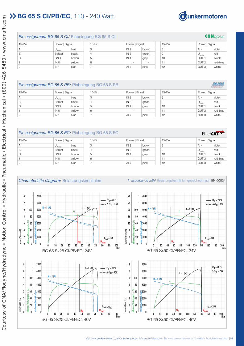
Pin assignment BG 65 S CI/ Pinbelegung BG 65 S CI
15-Pin Power | Signal 15-Pin Power | Signal 15-Pin Power | Signal
A UPower
blue 3 IN 2 brown 8 AI - violet
B Ballast black 4 IN 3 green 9 ULogic
red
C GND brwon 5 IN 4 grey 10 OUT 1 black
1 IN 0 yellow 6 - - 11 OUT 2 red-blue
2 IN 1 blue 7 AI + pink 12 OUT 3 white
η
0 10 20 30 40 50 60 70 80 90 100Ncm
7000
6000
5000
4000
3000
2000
1000
0
100
80
60
40
20
0
7
6
5
4
3
2
1
0 rate
d sp
eed/
Dreh
zahl
n(r
pm)
effic
ienc
y/W
irkun
gsgr
adη
(%
)
curr
ent/
Stro
mI(
A)
MN Mmax
ϑR = 20°C
ΔϑEl = 75K
ILimit=10A
J = f (M)
N = f (M)
0 20 40 60 80 100 120 140 160 180 200Ncm
7000
6000
5000
4000
3000
2000
1000
0
100
80
60
40
20
0
14
12
10
8
6
4
2
0 rate
d sp
eed/
Dreh
zahl
n (r
pm)
effic
ienc
y/W
irkun
gsgr
ad η
(%
)
curr
ent/
Stro
m I
(A)
MN
N = f (M)
J = f (M)
η
W
Mmax
ϑR = 20°C
Δϑ = 75K
ILimit=20A
BG 65Sx25 CI, 40 V BG 65Sx50 CI, 40 V
BG 65 Sx50 CI/PB/EC, 24VBG 65 Sx25 CI/PB/EC, 24V
BG 65 Sx25 CI/PB/EC, 40V BG 65 Sx50 CI/PB/EC, 40V
Characteristic diagram/ Belastungskennlinien In accordance with/ Belastungskennlinien gezeichnet nach EN 60034
Pin assignment BG 65 S PB/ Pinbelegung BG 65 S PB
15-Pin Power | Signal 15-Pin Power | Signal 15-Pin Power | Signal
A UPower
blue 3 IN 2 brown 8 AI - violet
B Ballast black 4 IN 3 green 9 ULogic
red
C GND brwon 5 IN 4 grey 10 OUT 1 black
1 IN 0 yellow 6 - - 11 OUT 2 red-blue
2 IN 1 blue 7 AI + pink 12 OUT 3 white
Pin assignment BG 65 S EC/ Pinbelegung BG 65 S EC
15-Pin Power | Signal 15-Pin Power | Signal 15-Pin Power | Signal
A UPower
blue 3 IN 2 brown 8 AI - violet
B Ballast black 4 IN 3 green 9 ULogic
red
C GND brwon 5 IN 4 grey 10 OUT 1 black
1 IN 0 yellow 6 - - 11 OUT 2 red-blue
2 IN 1 blue 7 AI + pink 12 OUT 3 white
Court
esy o
f CM
A/F
lodyne/H
ydra
dyne
Motion C
ontr
ol
Hydra
ulic
Pneum
atic
Ele
ctr
ical
Mechanic
al
(800)
426-5
480
ww
w.c
mafh
.com
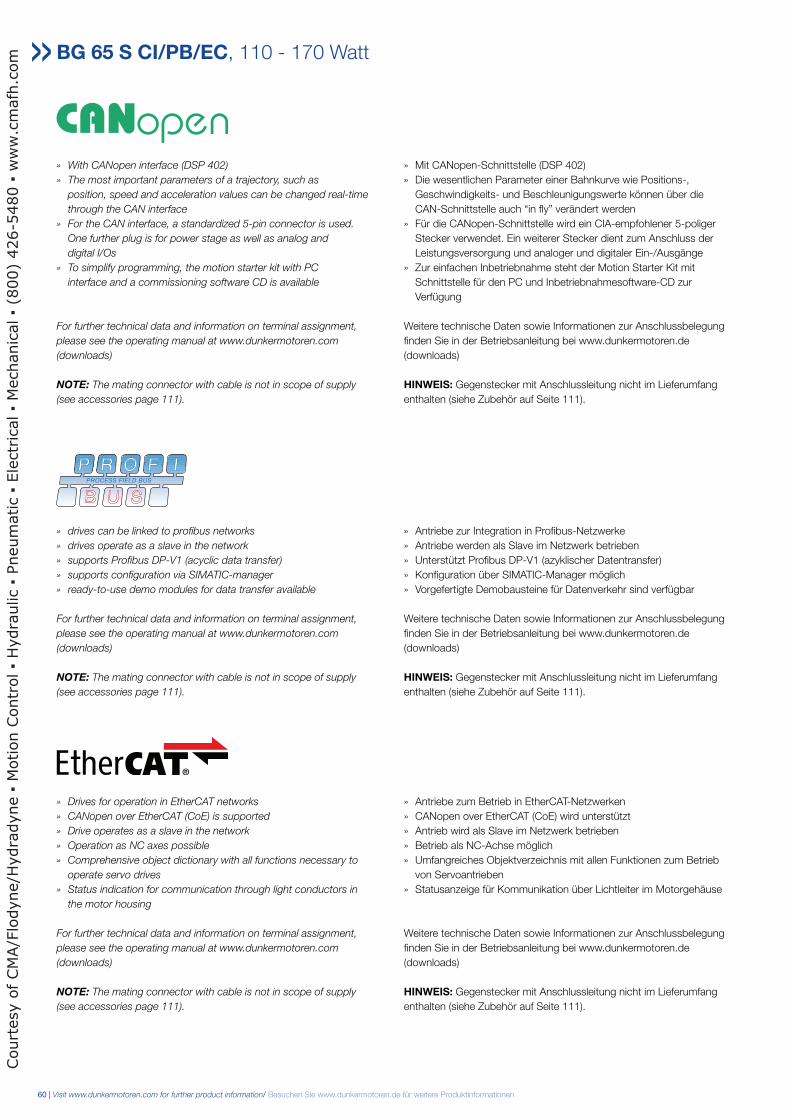
60 | Visit www.dunkermotoren.com for further product information/ Besuchen Sie www.dunkermotoren.de für weitere Produktinformationen
BG 65 S CI/PB/EC, 110 - 170 Watt
» With CANopen interface (DSP 402)
» The most important parameters of a trajectory, such as
position, speed and acceleration values can be changed real-time
through the CAN interface
» For the CAN interface, a standardized 5-pin connector is used.
One further plug is for power stage as well as analog and
digital I/Os
» To simplify programming, the motion starter kit with PC
interface and a commissioning software CD is available
For further technical data and information on terminal assignment,
please see the operating manual at www.dunkermotoren.com
(downloads)
NOTE: The mating connector with cable is not in scope of supply
(see accessories page 111).
» Mit CANopen-Schnittstelle (DSP 402)
» Die wesentlichen Parameter einer Bahnkurve wie Positions-,
Geschwindigkeits- und Beschleunigungswerte können über die
CAN-Schnittstelle auch “in fly” verändert werden
» Für die CANopen-Schnittstelle wird ein CIA-empfohlener 5-poliger
Stecker verwendet. Ein weiterer Stecker dient zum Anschluss der
Leistungsversorgung und analoger und digitaler Ein-/Ausgänge
» Zur einfachen Inbetriebnahme steht der Motion Starter Kit mit
Schnittstelle für den PC und Inbetriebnahmesoftware-CD zur
Verfügung
Weitere technische Daten sowie Informationen zur Anschlussbelegung
finden Sie in der Betriebsanleitung bei www.dunkermotoren.de
(downloads)
HINWEIS: Gegenstecker mit Anschlussleitung nicht im Lieferumfang
enthalten (siehe Zubehör auf Seite 111).
» drives can be linked to profibus networks
» drives operate as a slave in the network
» supports Profibus DP-V1 (acyclic data transfer)
» supports configuration via SIMATIC-manager
» ready-to-use demo modules for data transfer available
For further technical data and information on terminal assignment,
please see the operating manual at www.dunkermotoren.com
(downloads)
NOTE: The mating connector with cable is not in scope of supply
(see accessories page 111).
» Antriebe zur Integration in Profibus-Netzwerke
» Antriebe werden als Slave im Netzwerk betrieben
» Unterstützt Profibus DP-V1 (azyklischer Datentransfer)
» Konfiguration über SIMATIC-Manager möglich
» Vorgefertigte Demobausteine für Datenverkehr sind verfügbar
Weitere technische Daten sowie Informationen zur Anschlussbelegung
finden Sie in der Betriebsanleitung bei www.dunkermotoren.de
(downloads)
HINWEIS: Gegenstecker mit Anschlussleitung nicht im Lieferumfang
enthalten (siehe Zubehör auf Seite 111).
» Drives for operation in EtherCAT networks
» CANopen over EtherCAT (CoE) is supported
» Drive operates as a slave in the network
» Operation as NC axes possible
» Comprehensive object dictionary with all functions necessary to
operate servo drives
» Status indication for communication through light conductors in
the motor housing
For further technical data and information on terminal assignment,
please see the operating manual at www.dunkermotoren.com
(downloads)
NOTE: The mating connector with cable is not in scope of supply
(see accessories page 111).
» Antriebe zum Betrieb in EtherCAT-Netzwerken
» CANopen over EtherCAT (CoE) wird unterstützt
» Antrieb wird als Slave im Netzwerk betrieben
» Betrieb als NC-Achse möglich
» Umfangreiches Objektverzeichnis mit allen Funktionen zum Betrieb
von Servoantrieben
» Statusanzeige für Kommunikation über Lichtleiter im Motorgehäuse
Weitere technische Daten sowie Informationen zur Anschlussbelegung
finden Sie in der Betriebsanleitung bei www.dunkermotoren.de
(downloads)
HINWEIS: Gegenstecker mit Anschlussleitung nicht im Lieferumfang
enthalten (siehe Zubehör auf Seite 111).
Court
esy o
f CM
A/F
lodyne/H
ydra
dyne
Motion C
ontr
ol
Hydra
ulic
Pneum
atic
Ele
ctr
ical
Mechanic
al
(800)
426-5
480
ww
w.c
mafh
.com
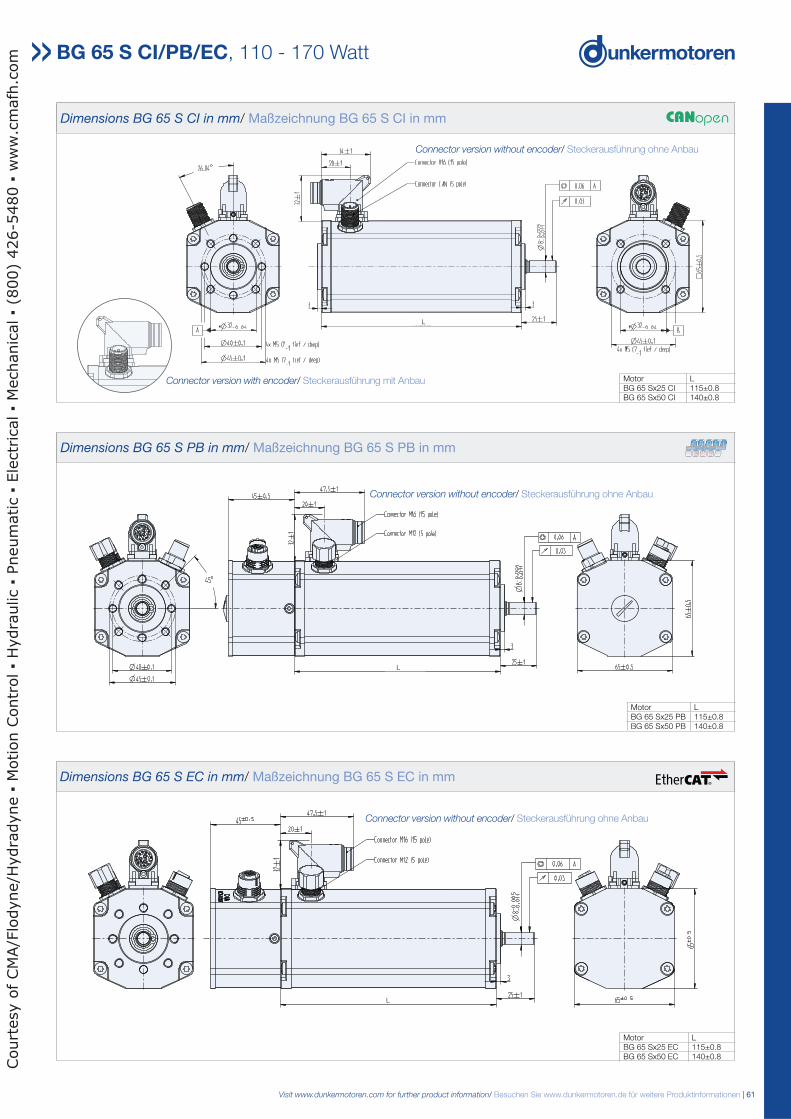
Visit www.dunkermotoren.com for further product information/ Besuchen Sie www.dunkermotoren.de für weitere Produktinformationen | 61
Dimensions BG 65 S CI in mm/ Maßzeichnung BG 65 S CI in mm
Motor LBG 65 Sx25 CI 115±0.8BG 65 Sx50 CI 140±0.8
BG 65 S CI/PB/EC, 110 - 170 Watt
Connector version without encoder/ Steckerausführung ohne Anbau
Connector version with encoder/ Steckerausführung mit Anbau
Dimensions BG 65 S PB in mm/ Maßzeichnung BG 65 S PB in mm
Dimensions BG 65 S EC in mm/ Maßzeichnung BG 65 S EC in mm
Motor LBG 65 Sx25 PB 115±0.8BG 65 Sx50 PB 140±0.8
Motor LBG 65 Sx25 EC 115±0.8BG 65 Sx50 EC 140±0.8
Connector version without encoder/ Steckerausführung ohne Anbau
Connector version without encoder/ Steckerausführung ohne Anbau
L
L
L
Court
esy o
f CM
A/F
lodyne/H
ydra
dyne
Motion C
ontr
ol
Hydra
ulic
Pneum
atic
Ele
ctr
ical
Mechanic
al
(800)
426-5
480
ww
w.c
mafh
.com
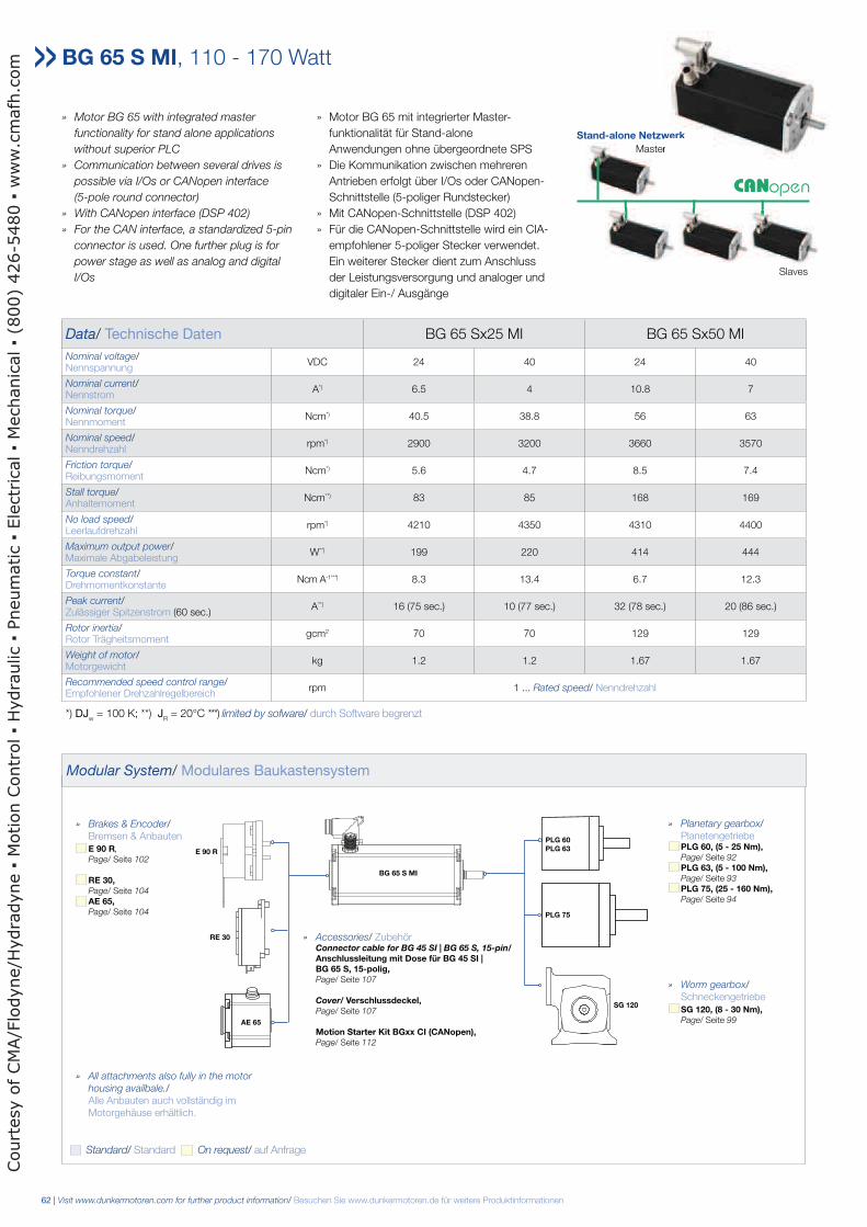
62 | Visit www.dunkermotoren.com for further product information/ Besuchen Sie www.dunkermotoren.de für weitere Produktinformationen
» Motor BG 65 with integrated master
functionality for stand alone applications
without superior PLC
» Communication between several drives is
possible via I/Os or CANopen interface
(5-pole round connector)
» With CANopen interface (DSP 402)
» For the CAN interface, a standardized 5-pin
connector is used. One further plug is for
power stage as well as analog and digital
I/Os
» Motor BG 65 mit integrierter Master-
funktionalität für Stand-alone
Anwendungen ohne übergeordnete SPS
» Die Kommunikation zwischen mehreren
Antrieben erfolgt über I/Os oder CANopen-
Schnittstelle (5-poliger Rundstecker)
» Mit CANopen-Schnittstelle (DSP 402)
» Für die CANopen-Schnittstelle wird ein CIA-
empfohlener 5-poliger Stecker verwendet.
Ein weiterer Stecker dient zum Anschluss
der Leistungsversorgung und analoger und
digitaler Ein-/ Ausgänge
Data/ Technische Daten BG 65 Sx25 MI BG 65 Sx50 MI
Nominal voltage/Nennspannung
VDC 24 40 24 40
Nominal current/Nennstrom
A*) 6.5 4 10.8 7
Nominal torque/Nennmoment
Ncm*) 40.5 38.8 56 63
Nominal speed/Nenndrehzahl
rpm*) 2900 3200 3660 3570
Friction torque/Reibungsmoment
Ncm*) 5.6 4.7 8.5 7.4
Stall torque/Anhaltemoment
Ncm**) 83 85 168 169
No load speed/Leerlaufdrehzahl
rpm*) 4210 4350 4310 4400
Maximum output power/Maximale Abgabeleistung
W**) 199 220 414 444
Torque constant/Drehmomentkonstante
Ncm A-1* * *) 8.3 13.4 6.7 12.3
Peak current/Zulässiger Spitzenstrom (60 sec.)
A**) 16 (75 sec.) 10 (77 sec.) 32 (78 sec.) 20 (86 sec.)
Rotor inertia/Rotor Trägheitsmoment
gcm2 70 70 129 129
Weight of motor/Motorgewicht
kg 1.2 1.2 1.67 1.67
Recommended speed control range/Empfohlener Drehzahlregelbereich
rpm 1 ... Rated speed/ Nenndrehzahl
*) DJw = 100 K; **) J
R = 20°C ***) limited by sofware/ durch Software begrenzt
BG 65 S MI, 110 - 170 Watt
Modular System/ Modulares Baukastensystem
Stand-alone Netzwerk
Slaves
Master
» Planetary gearbox/ Planetengetriebe PLG 60, (5 - 25 Nm), Page/ Seite 92
PLG 63, (5 - 100 Nm), Page/ Seite 93
PLG 75, (25 - 160 Nm), Page/ Seite 94
» Worm gearbox/ Schneckengetriebe SG 120, (8 - 30 Nm), Page/ Seite 99
» Brakes & Encoder/ Bremsen & Anbauten E 90 R,
Page/ Seite 102
RE 30, Page/ Seite 104
AE 65, Page/ Seite 104
» Accessories/ Zubehör Connector cable for BG 45 SI | BG 65 S, 15-pin/ Anschlussleitung mit Dose für BG 45 SI | BG 65 S, 15-polig, Page/ Seite 107
Cover/ Verschlussdeckel, Page/ Seite 107
Motion Starter Kit BGxx CI (CANopen), Page/ Seite 112
PLG 75
SG 120
RE 30
E 90 R
BG 65 S MI
PLG 60 PLG 63
Standard/ Standard On request/ auf Anfrage
» All attachments also fully in the motor
housing availbale./ Alle Anbauten auch vollständig im Motorgehäuse erhältlich.
zwerk
ter
AE 65
Court
esy o
f CM
A/F
lodyne/H
ydra
dyne
Motion C
ontr
ol
Hydra
ulic
Pneum
atic
Ele
ctr
ical
Mechanic
al
(800)
426-5
480
ww
w.c
mafh
.com
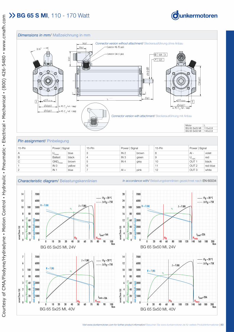
Visit www.dunkermotoren.com for further product information/ Besuchen Sie www.dunkermotoren.de für weitere Produktinformationen | 63
0 10 20 30 40 50 60 70 80 90 100Ncm
7000
6000
5000
4000
3000
2000
1000
0
100
80
60
40
20
0
14
12
10
8
6
4
2
0 rate
d sp
eed/
Dreh
zahl
n(r
pm)
effic
ienc
y/W
irkun
gsgr
adη
(%
)
curr
ent/
Stro
mI(
A)
MN
η η
0 20 40 60 80 100 120 140 160 180 200Ncm
7000
6000
5000
4000
3000
2000
1000
0
100
80
60
40
20
0
28
24
20
16
12
8
4
0 rate
d sp
eed/
Dreh
zahl
n(r
pm)
effic
ienc
y/W
irkun
gsgr
adη
(%
)
curr
ent/
Stro
mI(
A)
MN MmaxMmax
ϑR = 20°C
ΔϑEl = 75K
ϑR = 20°C
ΔϑEl = 75K
ILimit=16A ILimit=32A
J = f (M)J = f (M)N = f (M) N = f (M)
BG 65Sx50 MI, 24 VBG 65Sx25 MI, 24 V
Pin assignment/ Pinbelegung
15-Pin Power | Signal 15-Pin Power | Signal 15-Pin Power | Signal
A UPower
blue 3 IN 2 brown 8 AI - violet
B Ballast black 4 IN 3 green 9 ULogic
red
C GNDPower
brown 5 IN 4 grey 10 OUT 1 black
1 IN 0 yellow 6 11 OUT 2 red-blue
2 IN 1 blue 7 AI + pink 12 OUT 3 white
Dimensions in mm/ Maßzeichnung in mm
Motor LBG 65 Sx25 MI 115±0.8BG 65 Sx50 MI 140±0.8
BG 65 S MI, 110 - 170 Watt
BG 65 Sx50 MI, 24V
η
0 10 20 30 40 50 60 70 80 90 100Ncm
7000
6000
5000
4000
3000
2000
1000
0
100
80
60
40
20
0
7
6
5
4
3
2
1
0 rate
d sp
eed/
Dreh
zahl
n(r
pm)
effic
ienc
y/W
irkun
gsgr
adη
(%
)
curr
ent/
Stro
mI(
A)
MN Mmax
ϑR = 20°C
ΔϑEl = 75K
ILimit=10A
J = f (M)
N = f (M)
0 20 40 60 80 100 120 140 160 180 200Ncm
7000
6000
5000
4000
3000
2000
1000
0
100
80
60
40
20
0
14
12
10
8
6
4
2
0 rate
d sp
eed/
Dreh
zahl
n (r
pm)
effic
ienc
y/W
irkun
gsgr
ad η
(%
)
curr
ent/
Stro
m I
(A)
MN
N = f (M)
J = f (M)
η
W
Mmax
ϑR = 20°C
Δϑ = 75K
ILimit=20A
BG 65Sx25 MI, 40 V BG 65Sx50 MI, 40 V
BG 65 Sx25 MI, 24V
BG 65 Sx25 MI, 40V BG 65 Sx50 MI, 40V
Characteristic diagram/ Belastungskennlinien In accordance with/ Belastungskennlinien gezeichnet nach EN 60034
Connector version without attachment/ Steckerausführung ohne Anbau
Connector version with attachment/ Steckerausführung mit Anbau
L
Court
esy o
f CM
A/F
lodyne/H
ydra
dyne
Motion C
ontr
ol
Hydra
ulic
Pneum
atic
Ele
ctr
ical
Mechanic
al
(800)
426-5
480
ww
w.c
mafh
.com