MONTGOMERY PARK REPOSITIONING 100% SCHEMATIC …
16
MONTGOMERY PARK REPOSITIONING 100% SCHEMATIC DESIGN – STRUCTURAL NARRATIVE DECEMBER 04, 2020 The purpose of this narrative is to provide guidance for the preparation of a preliminary construction budget for the repositioning of the Montgomery Park building during schematic design phase. Montgomery Park Building Description Building History Montgomery Park is an existing nine-story building that has been occupied by primarily office and retail tenants since a major renovation in the mid-1980s. Previous to its current occupancy it was used as a retail department store. It was originally constructed as a distribution warehouse for Montgomery Ward. The building was built in two phases. The first phase in 1920 created the southern and eastern legs in an “L” configuration. The second phase added the north leg in 1935 that completed the current “U” shape configuration. During a renovation in the mid-1980s the open U was converted to an enclosed atrium with a sloped skylight roof. An infill second story was also added to connect the northern and southern legs of the U shape. In addition, a three-story glazed entrance was added to the west end of the atrium. Figure 1: Construction History
Transcript of MONTGOMERY PARK REPOSITIONING 100% SCHEMATIC …
MONTGOMERY PARK REPOSITIONING 100% SCHEMATIC DESIGN – STRUCTURAL NARRATIVE
DECEMBER 04, 2020
The purpose of this narrative is to provide guidance for the preparation of a preliminary construction
budget for the repositioning of the Montgomery Park building during schematic design phase.
Montgomery Park Building Description
Building History
Montgomery Park is an existing nine-story building that has been occupied by primarily office and
retail tenants since a major renovation in the mid-1980s. Previous to its current occupancy it was
used as a retail department store. It was originally constructed as a distribution warehouse for
Montgomery Ward.
The building was built in two phases. The first phase in 1920 created the southern and eastern legs
in an “L” configuration. The second phase added the north leg in 1935 that completed the current
“U” shape configuration. During a renovation in the mid-1980s the open U was converted to an
enclosed atrium with a sloped skylight roof. An infill second story was also added to connect the
northern and southern legs of the U shape. In addition, a three-story glazed entrance was added to
the west end of the atrium.
Figure 1: Construction History

Montgomery Park Repositioning 2 KPFF Project No. 10021900733
100% SD Structural Narrative December 04, 2020
Structural Arrangement
The existing building is nine stories tall with a plan dimension of approximately 280 by 300 feet. The
east side of the building has a small portion that extends 40 additional feet to the east. The north half
of the building has a one-story basement that is 120 by 280 feet in plan. The building has
approximately 750,000 ft2 of space (not including the basement and penthouses).
The building has a large skylight that slopes upward west to east. The skylight starts on the west side
at the fourth floor and slopes up five stories towards the east side of the building. A portion of the
eastern skylight is flat.
The typical floor to floor height is 12’-6”. However, the height between the first and second floors is
18’-9” and the height between the second floor and the fourth level is 17’-3’. The height between the
ninth floor and roof is 15’-9”.
Figure 2: Basement Plan (left) and Section (right)
The building is founded on large shallow foundations that are reinforced concrete. The typical footing
size is 14’ square and 30” deep, and are generally spaced at 20’ on center.
Columns are typically round concrete on the interior. If the columns are exterior or were on the
exterior before the 1935 addition, then they are rectangular. Typically, the rectangular columns have
a round column rebar arrangement with unreinforced rectangular corners.
The slab-on-grade at the basement level is 6” thick. The structured floors are either 6¾” or 8¾” thick
reinforced two-way slab supported by drop panels and column capitals. The roof level is either 5½”
slab or 6¾” thick reinforced two-way slab supported by drop panels and column capitals.
The exterior building walls are built with concrete columns supporting concrete spandrel beams with
brick infill walls below the concrete windowsills.
The existing lateral load-resisting system would be classified as a concrete moment frame with
concrete diaphragms. However, this system is not currently recognized by the Oregon Structural
Specialty Code (OSSC) due to its lack of ductility and detailing.

Montgomery Park Repositioning 3 KPFF Project No. 10021900733
100% SD Structural Narrative December 04, 2020
For a building of this age the concrete is generally consolidated and in satisfactory condition.
However, there are many instances of deterioration witnessed by KPFF during a partial walkthrough
of the building and based on previous reports. The deterioration witnessed was primarily located in
the basement and the external façades of the building frame.
Building Repositioning
Scope of Repositioning
The Montgomery Park property was acquired by the client in 2019 who appointed a design team
consisting of GBD Architects and S9 Architecture to reposition the building in the market. The
repositioning effort is focused on maintaining the current office tenants and expanding the ground
floor and roof retail, restaurant, and amenity offerings.
To date, the repositioning effort has resulted in schematic floor layouts for each of the stories. There
are minor structural alterations that will be necessary to achieve the concepts that include local
reinforcing necessary to cut openings into existing structural elements, the addition of staircases, and
structural framing to support new multistory storefront at the western entrance. There are also
enclosed penthouses and open terraces intended to be created on the roof.
The majority of the structural input to the repositioning effort is related to seismic design
implications. The construction of Montgomery Park pre-dates structural building codes, and most
significantly, the wind and seismic loading requirements of modern codes. During the concept design
stage it was decided to undertake a voluntary seismic retrofit approach in lieu of a more rigorous
mandatory (current code-compliant) seismic retrofit.
Mandatory Seismic Retrofit Triggers
Given that a voluntary seismic retrofit has been targeted, it is imperative the proposed repositioning
effort does not trigger a mandatory seismic retrofit.
Since this repositioning is not changing the current office and retail occupancy, a limited renovation
would not necessarily result in a mandatory seismic retrofit. It is important to note that during a
voluntary retrofit the repositioning alterations may not diminish the performance of the existing
structure in a seismic event. Since the building is intended to remain occupied during the renovation,
this requirement would apply to both the temporary (during-construction) and final states of the
renovation.
The criteria that would trigger a mandatory retrofit can be found in two locations:
• An occupancy-based trigger can be found in the City of Portland’s Title 24.85 document that
allows an existing occupancy to be increased by a maximum 149 occupants before a seismic
retrofit is mandated. This threshold is regardless of building size.

Montgomery Park Repositioning 4 KPFF Project No. 10021900733
100% SD Structural Narrative December 04, 2020
Figure 3: Table 24.85-B from Title 24.85
During the previous 2014 OSSC code cycle, the occupancy trigger of Title 24.85 was
superseded by the Statewide Alternate Method (SAM). The SAM instead allowed a 10%
increase in current occupant count before triggering a mandatory seismic retrofit. This
approach allowed larger buildings such as Montgomery Park a greater increase in occupant
count.
However, the SAM has yet to be renewed for the current 2019 OSSC code cycle, leaving
uncertainty in how the City will process voluntary seismic retrofit projects. Our office is aware
of recent projects under the City’s jurisdiction where the SAM was adopted successfully after
the code cycle change. Nevertheless, we recommend seeking their project-specific
interpretation as soon as is practical to mitigate risk.
• The remaining mandatory retrofit trigger can be found in section 3405.2 of the 2019 Oregon
Specialty Structural Code (OSSC) as modified from the 2018 International Existing Building
Code (IEBC). This second trigger is determined on a structural capacity basis. In general, if the
demand-to-capacity ratio (DCR) of an individual member increases by more than 10% as the
result of a renovation, then a mandatory seismic retrofit is triggered. The application of this
provision was used to determine the maximum size non-triggering penthouse addition that
would be allowed. The specific code language is inserted below:
Figure 4: Excerpt from the 2019 OSSC / 2018 IEBC

Montgomery Park Repositioning 5 KPFF Project No. 10021900733
100% SD Structural Narrative December 04, 2020
Structural Additions at Roof
At the concept design stage, a penthouse that does not trigger a mandatory seismic retrofit was
decided upon. The basis for determining the maximum area that would be allowed is discussed
below:
• The approximate footprint of the penthouse buildout was determined by assuming the
seismic weight of the new additions and applying the OSSC section 3405.2 exception
described previously in this report. This approach yields a maximum additional penthouse
weight of 800,000 lbs. if the penthouse is placed centrally on the roof (640,000 lbs. if placed
eccentrically). This allowance is to include any additional MEP equipment and landscaping.
Figure 5: Example Penthouse Concentric Layout
The below approximate structural weights have been provided to the design team to assist in
sizing the penthouse area based on weight without triggering a mandatory seismic retrofit:
o Enclosed “heavy” Penthouse: 85-90 lbs./SF: This is a steel floor structure supporting
slab on metal deck (SOMD) floor. The walls are metal stud light framing. The roof is
steel open web joists with metal roof decking.
o Enclosed “light” Penthouse: 60 lbs./SF: This is the same as above but with a plywood
and gypcrete floor (instead of SOMD).
o Open “heavy” Terrace: 35 lbs./SF: This is a steel floor structure supporting a pedestal
paver system.
o Open “light” Terrace: 20 lbs./SF: This is a steel floor structure supporting open
decking on wood joists.
Montgomery Park Repositioning 6 KPFF Project No. 10021900733
100% SD Structural Narrative December 04, 2020
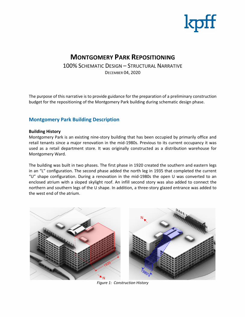
Voluntary Seismic Retrofit
In terms of OSSC and ASCE 7-16, Montgomery Park would be classified as a Risk Category III structure
due to its net occupancy exceeding 5,000 occupants. This risk category is defined as a, “structure that
represents a substantial hazard to human life in the event of a failure”. Structures in Risk Category III
are designed to a higher structural performance objective than typical buildings. The current code-
level seismic performance objective that would satisfy a mandatory seismic retrofit is noted in the
below chart as “BPOE”, the “Basic Performance of Existing Buildings”. However, this being a voluntary
retrofit, the BSE-1N hazard has been targeted at a Life Safety performance level. It is worth noting
that this seismic performance objective is considered code-level for new risk category II structures.
Figure 6: Seismic Performance Objective for Montgomery Park Voluntary Retrofit
New Lateral Force Resisting System Layout
There are currently 3 shear wall layouts being considered by the design team that would meet the
defined performance objective:
• Baseline – “4 Wall” Shear Wall Layout (sketch provided below)
• Alternate 1 – “Box Cores Opening into Atrium” Shear Wall Layout (sketch provided below)
• Alternate 2 – “Box Cores Opening onto Floor Plate” Shear Wall Layout (similar to Alt. 1)
At this stage in the design, each option will contain similar material quantities of concrete and rebar
in both the walls and their foundations. Schematic level collector layouts and weights have been
provided in the 100%SD sketches. Due to centralizing the heavy construction, it is anticipated that
alternates 1 and 2 will find cost and time savings due to reducing build-back costs, minimizing tenant
disruption, and limiting impacts to MEP services.

Montgomery Park Repositioning 7 KPFF Project No. 10021900733
100% SD Structural Narrative December 04, 2020
Figure 7: Plan of Proposed “4 Wall” Baseline Shear Wall Layout
Figure 8: Plan of Proposed “Box Core” Alternate Shear Wall Layout

Montgomery Park Repositioning 8 KPFF Project No. 10021900733
100% SD Structural Narrative December 04, 2020
New Lateral Force Resisting System Components
The below components of the lateral force resisting system will be common to all shear wall layout
options.
• Special reinforced concrete shear walls form the new lateral force resisting system (LFRS).
The shear walls are to be placed concentrically about the middle of the building in plan and
continuous between the foundation and the roof. The wall thickness will vary between 27”,
21”, and 16” as indicated in the 100%SD sketches. The thickness of the walls forming the
elevator bays will remain constant for the full building height. Inboard walls that are cast
between floor slabs will transition between thicknesses at the seventh floor as agreed. All
new walls are required to be constructed beginning at the foundation and working
sequentially up to the roof.
We estimate 350 pounds per cubic yard (lbs./cy) of rebar will be placed in the walls. Vertical
rebar will be 60 ksi, A706 grade, and horizontal and confinement rebar may be either grade
A615 or grade A706. Confinement rebar at the wall ends will be 80 ksi to reduce boundary
element congestion. It is anticipated that the vertical wall rebar will be placed in cores created
in the existing slabs. Budget for pairs of vertical cores at 9” on center for the wall field bars.
(A reduction to 2.67 cores per lineal foot from the current 4 per lineal foot assumption.) While
not a requirement, mechanically coupling the vertical rebar with class B couplers may ease
construction and reduce long lap lengths. (Note that the field couplers would also be reduced
to 2.67 per lineal foot from the current 4 per lineal foot assumption.) The vertical rebar at the
ends and corners of each shear wall may pass through rectangular slots created in the slabs
in these zones. The slots are intended to ease construction of the densely reinforced
boundary elements. Depending on the location in slab span, temporary shoring may be
necessary.
Shear wall concrete strength is estimated to be 8 ksi at the bottom lifts. The concrete strength
will reduce as needed for wall strength as we move up the building to approximately 4-5 ksi
at the top. The walls may be conventionally formed or use shotcrete. If shotcrete is preferred,
any exposed surfaces shall be troweled to a sample-approved appearance.
Where walls connect to existing concrete surfaces, the existing surface will be clean, free of
laitance, and intentionally roughened to a ¼” amplitude. Exceptions to the intentional
roughening occur where shear walls cast between floors pass through existing slabs. The top
and bottom of the existing horizontal slab surfaces may instead be only clean and free of
laitance.
• Collectors are needed to connect the new shear walls adequately to the existing concrete
diaphragms. The collectors may be placed either on the soffit of the existing slabs or along
the slab edges around the atrium. Collectors may be hot-rolled steel sections, flat plate, or
cast concrete beams. The average weight of either rebar or hot-rolled steel contained in the
collectors is provided on plan. The collectors will be connected to the slab with adhesive
anchors placed in pairs at 9” on center typically. (A reduction to 2.67 anchors per lineal foot
from the current 4 per lineal foot assumption.) Note that any typical steel shapes are
appropriate and are to be chosen at the contractor’s preference (channels, wide flanges, WTs,

Montgomery Park Repositioning 9 KPFF Project No. 10021900733
100% SD Structural Narrative December 04, 2020
HSS, plate, bar) provided their yield strength is 50 ksi. The collectors do not require fire
protection.
• Mat foundations will be required to support the new concrete shear walls. The likely most
cost-effective foundation is to excavate between existing footings and pour a new large mat
footing that is adhesive doweled into the existing column footings. The average approximate
mat thickness is 4’-6” and their overall extent has been provided in the 100%SD sketches. The
mat foundations will contain approximately 275 lbs./cy of rebar and the anticipated concrete
strength is 5 ksi.
The previous narratives indicated the bottom of the new footings would coincide with the
bottom of the existing building footings. However, recent geotechnical studies have indicated
that the founding elevations can be raised to minimize excavation and backfill. Possible
configurations below should be compared on a cost basis:
o Mat Baseline – Bottom of mat foundation coinciding with the bottom of the existing
column footings. This option requires relatively deep excavation, backfill above the
mat, and a separate slab-on-grade. All adjoining sides of foundations would be
adhesive dowelled.
o Mat Alternate 1 – Top of mat foundation to be placed approximately 12” below
existing floor level. The 12” dimension is to allow for a 6-8” gravel layer below the
slab-on-grade to allow for chasing of future services. This option reduces excavation
and backfill and is likely best suited for the ground floor mat foundations. All adjoining
sides of foundations would be adhesive dowelled.
o Mat Alternate 2 – Top of mat foundation to coincide with top of existing slab-on-
grade. This option reduces excavation and backfill, and eliminates a separate slab-on-
grade. This may be best suited in the basement locations due to not allowing future
in-slab services chasing. Adhesive dowelling would be significantly reduced.
o Mat Alternate 3 – Bottom of mat foundation directly on top of existing slab on grade.
This eliminates all excavation, backfill, and a separate slab-on-grade. Adhesive
doweling would only occur between adjoining surfaces of the column faces and mat.
This option is only practical in the lower basement area. Head-height and disruption
of existing equipment, ducting, and services is to be considered. Also the geotechnical
study noted the presence of isolated under slab voids that would need to be surveyed
and locally improved.
When considering the above options, please refer to the recent geotechnical studies included
in the appendix of this narrative. Of note was the silt content encountered during sampling
that may require a 4” layer of compacted crushed rock be placed to allow for adequate
compaction.
It was determined during the concept stage that a micropile alternative is not viable due to
cost and time constraints.

Montgomery Park Repositioning 10 KPFF Project No. 10021900733
100% SD Structural Narrative December 04, 2020
• The external glazing represents a significant risk to life safety due to the likelihood that
individual annealed panes will shatter and become a falling hazard both internally and
externally. Options to remediate the life safety risk include application of transparent
protective window film to prevent glass fall-out in a seismic event. Or alternatively, replacing
the existing glazing with a modern system that accommodates building drift and provides
better thermal performance to the building.
General Comments on Allowances
• Allowance for repair of deteriorated concrete structure should be budgeted. This will
primarily occur at the exterior walls. A preliminary budget allowance of $1/ft2 was previously
provided. In recent discussions, the design team and client are considering reducing this
approximately $826,000 allowance by 50% or more.
• An appropriate allowance shall be included for the contractor’s chosen methods necessary to
perform the work indicated in its final condition in this narrative. This work includes but is not
limited to saw-cutting, coring, temporary shoring, and other similar work.
• Allowances for adhesive dowels for foundations, collectors, and shear wall work will need to
be assumed. Adhesive rebar doweling to assume the use of Hilti Hit HY200 with 40 bar
diameter embedment generally.
• Allowances to address working in an occupied building and removing and replacing building
finishes will need to be made.
• All rebar quantities given in this narrative do not include waste, hooks, laps, couplers, form
ties, chairs or bolsters, post-installed anchors, embeds, or similar accessories. The contractor
shall include appropriate allowances for these items.
• All structural steel quantities given are based on center to center spans and do not include
allowances for typical steel connection plates, angles, bolts, welds, pins, deck edge plates,
deck form closures, etc. They also do not include miscellaneous steel for support of MEP,
exterior cladding, window washing, elevators, stairs, architectural items, or other related
systems.
• Exposed structural steel is to be hot-dipped galvanized and painted. Exposed post-installed
anchors are to be hot-dipped galvanized.
Non-Seismic Structural Alterations
The structural alterations that have been identified by the repositioning team are presented below:
• Western Storefront and Operable Door Structural Support
Large operable glazed doors and storefront are intended at the western building entrance. A
backup steel structure and likely foundations will be required to support the storefront and doors.
This scope is intended to be more defined in the design development stage.

Montgomery Park Repositioning 11 KPFF Project No. 10021900733
100% SD Structural Narrative December 04, 2020
• New Floor Opening in Existing Slab
An opening is intended to be cut into the existing second floor slab. If the opening is created
without affecting the column capitals and drop-heads, then only minimal structural reinforcing
will be required. A larger opening will require further structural reinforcing consisting of steel WF
beams placed under the cut slab edges and spanning between columns.
Figure 9: Western Storefront (left) and Second Floor Opening (right) Structural Alterations
• Penthouse Construction
New penthouse structures will consist of an elevated steel-framed platform that span onto the
building’s existing 20’x20’ column grid. The overall thickness of the elevated steel structure is
approximately 36” comprised of composite W18 girders supporting composite W16 beams at
10’-0” on center (Allow 6.0 psf for steel floor framing). The floor is assumed to be 5½” slab on
metal deck (SOMD) spanning between the beams.
The walls and roof are assumed to be lightweight construction. The walls are to be metal stud
construction. The roof is to be streel framed on a 20’x40’ grid and will support 1.5” metal deck
roofing (Allow 4.0 psf for steel roof framing). Allow for a steel braced-frame lateral force resisting
system positioned on the perimeter of the new penthouse buildings. Example single-bay floor
and roof framing plans have been provided below:
Figure 10: Example Penthouse Framing Bays

Montgomery Park Repositioning 12 KPFF Project No. 10021900733
100% SD Structural Narrative December 04, 2020
• Roof Pathway Construction
Approximately 6’ wide pathways will be necessary to link the new penthouse buildings. Pending
further study of the existing concrete roof structure, it is likely that the pathways would require
additional structural support at roof level. Two options exist to provide this support:
o Installing wide flange stiffener beams below the roof that would span between the
existing column grid. The top of the beam would sit directly below the drop caps and
connect to the angled face of the column capitals with shaped plate and adhesive
anchors. The beam installation will affect ceilings, finishes, and possibly mechanical
equipment suspended from the slab soffit.
o Creating approximately 20’ long “bridges” that span between the existing column
grid. These platforms could be prefabricated and lifted into place on the roof. They
would attach above the existing columns with adjustable steel baseplates and
adhesive anchors. If fabricated from steel, an allowance of 8 psf would be
appropriate. If fabricated from aluminum, then 3-4 psf is appropriate. A schematic
detail has been provided below and in the 100% SD sketches.
Figure 11: Bridge Example Section
• Re-use of the Existing Rooftop Tank Room
The existing tank room positioned at roof level along the eastern edge of the building is proposed
to be repositioned as a restaurant occupancy. We do not anticipate the existing floor will need to
be strengthened to meet current code live load requirements. If large floor openings are cut into
the slab for new stair access from level 9, we anticipate using steel beams to strengthen the cut
slab edges. The edges would likely not require stiffening if an entire floor panel is removed
between existing column drop caps.
• Terrace Above Existing Rooftop Tank Room
The roof of the tank room is proposed to be used as an open terrace. It is assumed to be 5½” flat
slab construction as per the typical roof and designed for a 20 psf live load. In order to not trigger
Montgomery Park Repositioning 13 KPFF Project No. 10021900733
100% SD Structural Narrative December 04, 2020
a mandatory seismic retrofit by the OSSC section 3405.2 exception, the area of terrace would be
limited to 800 square feet. This is assuming steel platform construction supporting a “heavy”
terrace buildup as defined previously.
An option to avoid a mandatory seismic retrofit and make use of the full 4000 ft2 terrace would
be to replace the existing concrete slab with either a steel or wood framed lightweight roof. This
new roof would also be an excellent candidate for cross laminated timber (CLT) roof panels due
to the 20’x20’ grid. Two span configuration options have been provided in the 100% SD sketches.
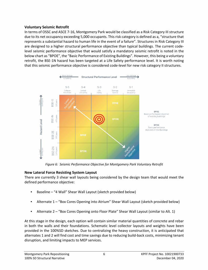
• Atrium Elevator Lobby Construction
A new elevator lobby is intended to be supported primarily by the new atrium shear walls. A
system of composite steel WF beams will span across the atrium and tie into the existing
triangular elevator lobby that was built in 1985 using SOMD construction. Due to the desire to
remove steel columns that currently support the existing triangular lobby, the new floor structure
will partially support the existing structure and loads from the 10th floor MEP area in the final
condition. The sequencing will require temporary shoring as means and methods. Further details
were provided by email to Walsh construction on September 2, 2020 and also included in the
100% schematic sketches.
Figure 12: Atrium Elevator Lobby Construction at Various Stages

Appendix A – Geotechnical Investigations APPENDIX A - MAT FOUNDATION MEMO

Appendix A – Geotechnical Investigations APPENDIX B - FOOTING ELEVATION STUDY

Appendix A – Geotechnical Investigations APPENDIX C - WINDOW FILM PRODUCT DATA