Montage Dielen Gb Web
4
Assembly Instructions Max Exterior Floor Boards/ Cassettes
-
Upload
isidora-djuric -
Category
Documents
-
view
4 -
download
0
description
exterior
Transcript of Montage Dielen Gb Web

Assembly InstructionsMax Exterior
Floor Boards/Cassettes
A
A
B
C
D
E
F
B
D
C
E
F
max. 500 mm
GB/1
Laying distances
For 16 mm thick floor boards, the distance to the sub-
structure must be a maximum of 500 mm (middle to
middle). This allows for a load of up to 3 kN/m. In case
you are unable to maintain a maximum distance for
constructive reasons, please contact our applications
engineering department. For special designs, it is pos-
sible to manufacture floor boards up to 20 mm thick—
with these, you can realize a distance of up to 800 mm
with the same load. The floor boards/cassettes are to
be fastened to every substructure bar. The substruc-
ture bars must be sufficiently supported, so that flexing
and slipping during assembly are prevented. To avoid
knocking or rattling later on, we recommend storing
them on rubber strips or similar.
Laying the floor boards/cassettes
� The floor boards/cassettes are mounted with open
joints. Water flow conditions and waterproofing need
to be guaranteed elsewhere.
� Assembly must be performed on a precisely aligned,
professionally laid substructure.
� Please be careful not to damage existing sealings
while laying the substructure.
� The downward slope of the floor boards/cassettes
must be at least 1.5% to one side.
� For staggered joints, floor boards or cassettes must
overlap laterally by a minimum of 250 mm.
� A substructure bar lies under every separator joint.
On it, both panel parts are fastened with a middle
clamp..
Laying optionsFloor board:
Surface width 220 mm + joint width 5 mm = 225 mm
surface area per floor board = 0.92 m2
Cassette:
Surface width 1000 x 450 mm + joints = 1005 x 455 mm
surface area per cassette = 0.45 m2
Assembly InstructionsMax Exterior Floor Boards/Cassettes
Foundation
Substructure
Axial distance (max. 500 mm)
Max Exterior floor boards aligned Max Exterior floor boards staggered
Accessories: Middle clamp, bottom/top clamp, separator, rubber mounting
Max Exterior floor boards/cassettes (surface Hexa)
Max Exterior cassettes aligned Max Exterior cassettes staggered
min.250 mm
min.250 mm
Top/bottom clamp
Middle clamp
Floor boards (16 mm)
GB/2
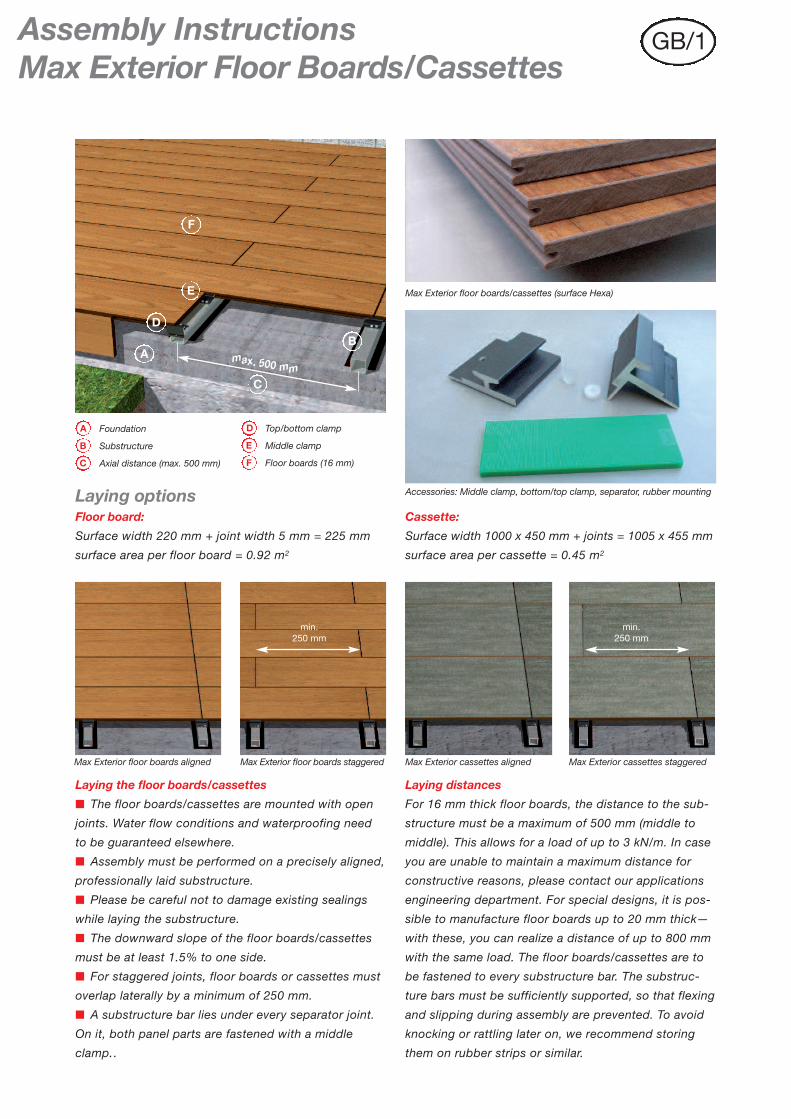
3) Top clamp assembly
Mount top clamps to every substructure so that they
are precisely aligned. To screw in the clamps to the
substructure, please use raised head/fillister head
screws with a maximum diameter of 3.8 mm.
6) Joints/displacement room
Moreover, the separator will secure the displacement
room necessary for the floor board/cassette.
(CAUTION: Remove afterwards!)
7) Completion
Should the final floor board/cassette need to be cut, it
must be fastened to the substructure using a fillister
head screw (no flathead!) or a commensurate
polyurethane façade adhesive.
4) Middle clamp assembly
Insert the floor board/cassette into the top clamp and fix
the floor board/cassette to the substructure bar with the
middle clamp. The rubber mounting (1x per board) on
the middle clamp prevent lateral slipping of the floor
board/cassette.
5) Mounting the next floor board
Prior to joining the next floor board/cassette, attach the
separators. You can press the next floor board tightly
to the previous and thereby guarantee a uniform joint
distance.
1) Subsurface preparation
The subsurface and substructure must have sufficient
static bearing capacity. A functioning minimum dis-
tance for ventilation of 25 mm to the subsurface must
be guaranteed.
Grass or similar is unsuitable as a subsurface!
Make sure the subsurface has sufficient drainage.
2) Substructure preparation
We recommend the use of standard aluminium forming
tubes as a substructure. Wood substructures need to
be properly protected from moisture. The substructure
must lie at a 90º angle to the floor board/cassette.
Assembly of floor boards/cassettes
FunderMax France3 Cours Albert ThomasF-69003 LyonTel.: + 33 (0) 4 78 68 28 31Fax: + 33 (0) 4 78 85 18 [email protected]
FunderMax India Pvt. Ltd.504, 5th floor, Brigade Towers135, Brigade RoadIND-560025 BangaloreTel.: +91 80 4111 7004Fax: +91 80 4112 [email protected]
JAGO AGIndustriestrasse 21CH-5314 KleindöttingenTel.: + 41 (0) 56-268 81 31Fax: + 41 (0) 56-268 81 [email protected]
ISOVOLTA S. A.UAvda. Salvatella, 85–97Poligono Industrial Can SalvatellaE-08210 Barberà del Vallès (Barcelona)Tel.: + 34-937 297 550Fax: + 34-937 190 [email protected]
ISO-MAX Spólka Akcyjnaul. Rybitwy 12PL-30 722 KrakauTel.: + 48-12-65 34 528Fax: + 48-12-65 70 [email protected]
FunderMax GmbHKlagenfurter Straße 87-89A-9300 St. Veit/GlanTel.: + 43 (0) 5/9494-0Fax: + 43 (0) 5/[email protected]
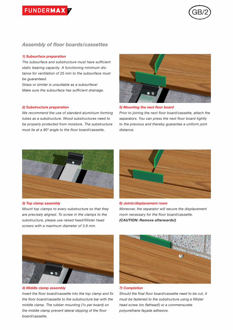
16 m
m
Maintain distance to fixedstructural elements
Fuge = 5 mmMiddle clamp
Separator Rubber strips
Mounting of the lastfloor board/cassette
Non-corrosivescrew
Edge cut from remaining floorboard/cassette
Cross-sectional view/M = 1 : 2
Load-bearingfoundation
Bottom clamp
Load-bearing capacity UK (e.g., aluminium forming tubes orwaterproof solid wood)
Floor board/cassette
� If you need to cut the final floor board/cassette
breadthwise, fasten it to the substructure using a fillis-
ter head screw (no flathead!) or a commensurate
polyurethane façade adhesive. Use the supplied 5 mm
discs as separators.
� To create attractive edges (e.g., to a lawn), top and
bottom clamps are available separately.
� Edge planks that match the design and requirements
of your construction can be manufactures using the
floor boards or cassettes. It is easy to cut matching
edge planks from the floor boards using suitable wood-
working tools.
� The longitudinal protrusion of the floor boards over
the substructure may not exceed 150 mm.
� The floor boards/cassette contracts and distends
from absorbing and releasing moisture. Therefore, lea-
ve a distance to fixed edges and buildings of at least
one separator.
� Max Exterior floor boards/cassettes are easily machi-
nable using carbide metal-equipped woodworking
tools. Saw using stable circular saws or circular hand
saws for assembly blanks. Drill by hand with high-
speed steel spiral drills, using a drill bit of < 90º. To
decrease risk of injury, we recommend chamfering cut
edges.
Additional information on processing Max Exterior
panels can be found in our brochure “Exterior
Technique” in the download section of our website:
HYPERLINK "http://www.fundermax.at“
Max Exterior Floor Boards/CassettesDetails
GB/30-10/11-P00019G
B.W
eb